1
User's
Manual
IM CW240P-E
CW240
Clamp-on Power Meter
Quick Setup Manual
IM CW240P-E
1st Edition: Jul 2004 (KP)
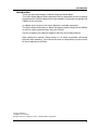
Introduction
Introduction
Thank you for purchasing our CW240 Clamp-on Power Meter.
This Quick Setup Manual briefly describes the key operations as well as setting
examples of the CW240 upon actual measurement, so that you can operate the
CW240 for the first time.
In addition to this manual, the User's Manual is available separately.
The User's Manual describes in detail the features and functions of the CW240
as well as safety measurements using the CW240.
Use the in-depth User's Manual together with this Quick Setup Manual.
After reading this manual, always keep it in an easily accessible convenient
place for later reference. This manual will come in handy when you are unsure
of how to operate the CW240.
Disk No. CW240P-E
1st Edition: Jul. 2004 (KP)
All Rights Reserved. Copyright © 2004, Yokogawa M&C Corporation
IM CW240P-E
1
Precautions for Safe Use of the
CW240
The following safety symbols are used on the CW240 and in this manual.
WARNING
Indicates a hazard that may result in the loss of life or serious injury of the user
unless the described instructions is abided by.
CAUTION
Indicates a hazard that may result in an injury to the user and/or physical
damage to the product or other equipment unless the described instructions is
abided by.
NOTE
Indicates information that is essential for handling the instrument or should be
noted in order to familiarize yourself with the instrument's operating procedure
and/or functions.
TIP
Indicates information that complements the present topic.
2
IM CW240P-E
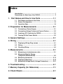
Index
Introduction ..................................................................................... 1
Precautions for Safe Use of the CW240 ....................................... 2
1. Part Names and How to Use Parts ......................... 1-1
1.1
1.2
Part Names and How to Use Parts ................................... 1-1
Screen Configuration ........................................................ 1-2
1.3
Operation Keys .................................................................. 1-8
2. Preparation for Measurements ................................ 2-1
2.1
2.2
Connecting a Power Supply ............................................. 2-1
Connecting Voltage Probes and Current Probes ............ 2-2
2.3
2.4
Inserting a PC Card into the CW240 ................................. 2-4
Turning ON the Power Switch ........................................... 2-5
3. General Settings ........................................................ 3-1
4. Wiring ......................................................................... 4-1
4.1
Displaying Wiring Diag. screen ........................................ 4-1
4.2
4.3
Wiring .................................................................................. 4-2
Checking Wiring ................................................................. 4-3
5. Measurements ........................................................... 5-1
5.1
Measuring an instantaneous value .................................. 5-1
5.2
Measuring Electric Energy
(Integration Measurement) ................................................ 5-5
5.3
5.4
Measuring Harmonics ..................................................... 5-13
Displaying Waveform ....................................................... 5-18
5.5
Measuring Voltage Qualit (Voltage Fluctuation) ............ 5-21
6. Troubleshooting ........................................................ 6-1
7. Memory Capacity (for Reference) ............................ 7-1
8. Check Sheets ............................................................. 8-1
IM CW240P-E
Toc-1
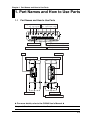
Chapter 1 Part Names and How to Use Parts
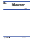
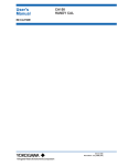
1. Part Names and How to Use Parts
1.1
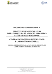
Part Names and How to Use Parts
Voltage input terminals
N U1 U2 U3
Current input terminals
CH1 CH2 CH3 CH4
Analog input terminals (optional)
RS-232 connector
External control I/O terminals
DA output terminals (optional)
PC card slot
LED
AC adapter jack
Power switch
Button for extracting a PC card
Battery holder
Battery holder lock switch
䉴 For more details, refer to the CW240 User's Manual 䉳
Chapter 2, "Part Names and How to Use Parts"
IM CW240P-E
1-1
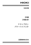
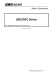
1.2
Screen Configuration
Basic Screen Configuration
F2
F1
START
F3
TOP
MENU
LIGHT
F4
ESC
F5
ENTER
&STOP
RANGE
A
RANGE
SAVE
DISP COPY
Measure screen
Setup screen
LIST (instantaneous values)
POWER
INTEGRATE
DEMAND
ZOOM
HARMONIC
(LIST, GRAPH, VECTOR)
WAVEFORM
(U & I WAVEFORM,
U WAVEFORM, I WAVEFORM)
VOLT. QUALITY
WIRING DIAGRAM
WIRING CHECK
GENERAL (1/2, 2/2)
SAVE (1/2, 2/2)
COMMUNICATION
VOLT. QUALITY
HARDWARE
ANALOG I/O (optional)
File screen
FILE NAME CHANGE
DELETE FILE
FORMAT
DATA COPY
SETTING FILE
BACKUP MEMORY COPY
BACKUP MEMORY DELETE
PROGRAM UPDATE
(normally not used)
䉴 For more details, refer to the CW240 User's Manual 䉳
Section, "2.4 Screen Configuration"
1-2
IM CW240P-E
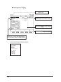
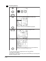
Displaying Measure Screen
● How to Display Measure Screen
TOP
MENU
Press the TOP MENU key.
Using the cursor key, select the MEASURE icon (highlighted).
ENTER
Press the ENTER key to display the Measure screen.
(The List screen is used as an example.)
IM CW240P-E
1-3
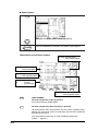
● Description of Display
Shows the integration measurement state.
STANDBY, INTEG., END, no indication
Shows the currently displayed load number
(when measuring multiple loads).
Name of the
screen displayed
Shows a mark.
• For the List and Power screens
INST., AVE, MAX., MIN.
• For the Volt. Quality screen
ALL, SWELL, DIP, INTER.
Shows the current date and time.
Shows setting items
common for each measurement.
Function key labels
• Wiring
• Number of loads *1
• Voltage range
• VT ratio
• Current range
• I4 (1P3W31, 3P4W4I)
• CT ratio
• Sampling method
• Frequency source/fixed clock
• Interval time
䉴 For more details, refer to the CW240 User's Manual 䉳
Section 7.2.2, "Description of Display"
1-4
IM CW240P-E
Displaying Setup Screen
● How to Display Setup Screen
TOP
MENU
Press the TOP MENU key. The Top Menu screen appears.
Using the cursor key, select the SETUP icon (highlighted).
ENTER
Press the ENTER key to display the top Setup screen.
Using the cursor key, select VARIOUS SETUP (highlighted).
ENTER
Press the ENTER key to display the Setup screen.
(The List screen is used as an example.)
IM CW240P-E
1-5
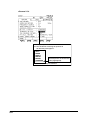
● Description of Display
Tab: Use the cursor key to
select a tab.
These show that the right and
left direction cursor key is active.
Cursor key: Moves to any setting
items.
F1
F2
F3
F4
F5
Function keys: Use these keys to
make each setting.
These show that up and down direction
cursor key is active, and appear only if
there are two or more tab setting pages.
<Items consisting of Setup screen>
General 1/2,
General 2/2,
Save 1/2,
Save 2/2,
Communication,
Volt. Quality,
Hardware,
Analog I/O
(optional)
1-6
IM CW240P-E
Description of Mark Indication
Appears if a voltage overrange occurs.
Appears if a current overrange occurs.
Appears when integration measurement is made by external input control.
Appears in the event of loss of PLL synchronization. This automatically selects the
fixed clock.
Appears when a reactive power meter method is used.
Appears when display hold is enabled.
Appears if the amount of data exceeds the capacity of a PC card or the internal memory.
Appears when the CW240 is configured so that data is saved in a PC card. Also, this
mark blinks during an access to the PC card.
Appears when data has been saved in the backup memory.
Appears when the CW240 is configured so that data is saved in the internal memory.
Also, this mark blinks during an access to the internal memory.
Appears if the CW240 is in a key lock state.
Appears when the CW240 is configured so that the RS-232 connection destination is
a PC. Also, this mark blinks during communication with the PC.
Appears if the CW240 is configured so that the RS-232 connection destination is a
printer. Also, this mark blinks during communication with the printer.
Appears if the CW240 is powered through the AC adapter.
Appears when the CW240 is powered through alkaline batteries or a NiMH battery
pack. This mark indicates a battery voltage reduction (remaining capacity) in four
steps.
䉴 For more details, refer to the CW240 User's Manual 䉳
Section 2.6, "Description of Mark Indication"
IM CW240P-E
1-7
1.3
Operation Keys
F1
START
&STOP
LIGHT
RANGE
F2
F3
F4
TOP
MENU
ESC
A
Key Name
SAVE
RANGE
F5
ENTER
DISP COPY
Functional Description
Function keys
F 1 to F 5
These are setting keys corresponding to the information displayed in the bottom
of the screen.
START & STOP key
Starts/stops integration measurements.
LIGHT key
Turns the backlight ON/OFF.
When held down for more than 3 seconds, it locks or unlocks the operation keys.
TOP MENU key
Switches the display screen to the Top Menu
ESC key
ENTER key
Cancels setup conditions or other data.
Confirms setup conditions or other data.
Cursor key
Moves the cursor to the item you wish to select.
U RANGE key
Changes the voltage range.
A RANGE key
Changes the current range.
SAVE key
Manually save or print measured data.
DISP COPY key
Hard-copies information displayed on the screen.
Copy destination setting: PC card, internal memory, or printer
䉴 For more details, refer to the CW240 User's Manual 䉳
Section 2.2, "Operation Keys"
1-8
IM CW240P-E
Chapter 2 Preparation for Measurements
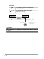
2. Preparation for Measurements
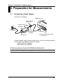
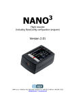
2.1
Connecting a Power Supply
Connect the AC adapter.
CW240 main unit
Attach the filter
to the cord.
Approx. 10 cm
AC adapter
<4> Connect
Clamp filter
A1193MN
<3> Connect
<2> Connect
<1> Check that the power switch
is turned OFF.
As backup power supply during a power failure, one of the following batteries
can be used. Use it together with the AC adapter.
• Alkaline batteries (supplied)
• NiMH battery pack (optional)
䉴 For more details, refer to the CW240 User's Manual 䉳
Section 3.2, "Connecting a Power Supply"
IM CW240P-E
2-1
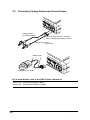
Connecting Voltage Probes and Current Probes
LOGI
C NI H L
PUT
STAR H
T/ST
OP
STAR H
T/ST
OP
L
CH
1
H
H
L
2.2
L
C
H
2
5.5
V
L
H
MA
X
LOGI
C NI H L
PUT
MA
X
H
1
5.5
V
L
C
v3
L
v2
v1
CA
T.
MA
X TO
O EA
RTH
RT
H
N
600V PUT
MA TE
X
RM
INAL
S 60
0V
V IN
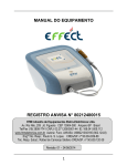
Voltage probes,
red, yellow, or blue
Insert the plug so that it is fastened
with a voltage input terminal securely.
Voltage probe, black
(N terminal)
LOG
IC N H
IPU L
T
STA
TAR H
T/S
TO
TOP
CH
1
H
H
L
H
MA
X
5.5V
L
H
C
L
H
LOG
IC N H
IPU L
T
S
L
2
TAR
TA
T/S
TO
TOP
Marker chips
MA
X
H
C
1
5.5V
L
v3
L
v2
v1
CAAT
.
N
600V PUT
-M
MA
X
V IN
TE
RM
INA
LS
600V
-M
AX
TO
O EA
RTH
Clamp-on current probe
䉴 For more details, refer to the CW240 User's Manual 䉳
Section 3.3, "Connecting Voltage Probes"
Section 3.4, "Connecting Clamp-on Probes"
2-2
IM CW240P-E
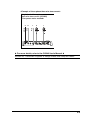
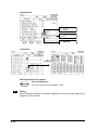
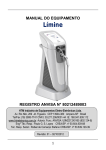
<Example of three-phase three-wire two-current>
Single load of three-phase
three-wire two-current (3P3W2I)
<Two-power-meter method>
S
R
T
R
T
Blue
Red
Black
䉴 For more details, refer to the CW240 User's Manual 䉳
Section 3.5, "Connection Diagrams of Voltage Probes and Clamp-on Probes"
IM CW240P-E
2-3
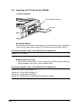
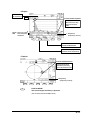
2.3
Inserting a PC Card into the CW240
<Insertion method>
PC Card Removal Button
PC Card
● Insertion Method
With the front surface of the card facing up (the direction the arrow is pointing),
insert the PC card securely into the PC card slot on the side of the CW240.
䉴 For more details, refer to the CW240 User's Manual 䉳
Chapter 11, "PC Card"
● Saving Data to PC Card
• Data can be saved to the PC card, as well as the CW240's internal memory.
• Setup conditions (set values) can be loaded/saved.
䉴 For more details, refer to the CW240 User's Manual 䉳
Section 6.4, "Save Data Settings 1/2"
Section 6.5, "Save Data Settings 2/2"
Chapter 8, "Saving Measured Data"
Section 9.6, "Setting Files (Load/Save/Delete/Name Change)"
2-4
IM CW240P-E
2.4
1
Turning ON the Power Switch
Model Name Screen
When the power switch is turned ON, the CW240 displays the following startup screen for
approx. 2 seconds.
2
Message Screen
This screen displays the model, version number, the presence of options, and self-check
results.
CW240 VER 1.00
FPGA Check OK
SDRAM Check OK
SRAM Check OK
Flash Disk Check OK
RTC Check OK
EEPROM Check OK
Setting Check OK
Option:Analog In/Out
3
When the self-check has been completed normally, the screen displayed when you
previously turned OFF the CW240 appears.
To switch to the Top Menu screen shown on the
left, press the TOP MENU key.
TOP
MENU
䉴 For more details, refer to the CW240 User's Manual 䉳
Section 3.6, "Turning ON the Power Switch"
IM CW240P-E
2-5
Chapter 3 General Settings
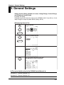
3. General Settings
Setting Up the Wiring, Number of Loads, Voltage Range, Current Range,
and Clamp-on Current Probe
Example of Setting:
Setting three-phase three-wire two-current (3P3W2I) 200-V line (50 Hz, 120-A
load) using the clamp-on probe 96030 (rating: 200 A)
● Displaying General Tab
TOP
MENU
Displays SETUP.
ENTER
Selecting VARIOUS SETUP.
ENTER
The General 1/2 screen is displayed.
Use up and down direction cursor key.
The General 2/2 screen is displayed.
䉴 For more details, refer to the CW240 User's Manual 䉳
Section 6.2, "General Settings 1/2"
Section 6.3, "General Settings 2/2"
IM CW240P-E
3-1
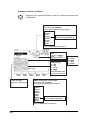
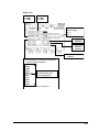
Displaying General 1/2 Screen
Using the right and left direction cursor key, select the General tab
(highlighted).
Wiring
Press the F1 key (CHANGE).
The window for selecting wiring appears.
3P3W+1P3W
3P4W4I
3P4W
3P3W3I
3P3W2I
1P3W3I
1P3W
1P2W
Using the cursor key, select a
desired wiring (highlighted).
Press the ENTER key to confirm it.
Load
F1
F1 : LOAD 1
F2
F2 : LOAD 2
Current range
F1 : 20A
F2 : 50A
F3 : 100A
F4 : 200A
F1
F2
F3
F4
F5
F1 : 150V
F2 : 300V
F3 : 600V
F4 : 1000V
Varies depending on the
clamp-on current probe.
VT and CT ratios
Model of clamp-on current probe
Cursor key : Digit change
F1 : +
F2 : –
Press the F1 key (CHANGE).
The window for selecting model appears.
96035_02
96035_1
96034_3
96034_2
96034_1
96032
96031
96030
96033
96036
Voltage range
Using the cursor key, select a
desired model (highlighted).
Press the ENTER key to confirm it.
3-2
IM CW240P-E
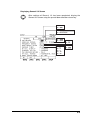
Displaying General 2/2 Screen
After settings of General 1/2 has been completed, display the
General 2/2 screen using the up and down direction cursor key.
F1 : ON
F2 : OFF
F1 : PLL synchronization
F2 : Fixed clock
F1 : 50Hz
F2 : 60Hz
F1 : 1
F2 : 2
F3 : 5
F4 : 10
F5 : 20
F1
IM CW240P-E
F2
F3
F4
F1 : U1
F2 : U3
F1 : ON
F2 : OFF
F5
3-3
Chapter 4 Wiring
4. Wiring
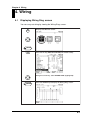
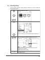
4.1
Displaying Wiring Diag. screen
You can carry out wiring by viewing the Wiring Diag. screen.
TOP
MENU
Displays the Measure screen.
ENTER
F1
Press the F1 key (DISPLAY CHANGE) for window callup.
Using the cursor key, select WIRING DIAG. (highlighted).
ENTER
IM CW240P-E
Press the ENTER key to display the Wiring Diag. screen.
4-1
4.2
Wiring
WARNING
• When attaching voltage probes to or clamping a clamp-on current probe on
the circuit under test, turn off power to the circuit under test.
It is extremely dangerous to connect or disconnect a voltage probe or clamp
or unclamp a clamp-on current probe without turning off the circuit under test.
• Be sure to connect voltage probes to or clamp a clamp-on current probe on
the secondary side of the circuit under test, such as current limiters (circuit
breakers). Should an accident such as a short occur, other circuits will be
protected by these circuit breakers.
Viewing the Wiring Diag. screen, attach voltage probes to or clamp clamp-on
current probes on the circuit under test.
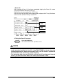
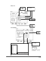
● Actual Wiring
1R
1R
Power 2S
supply
2S
3T
3T
Load
Blue
Red
Black
<Clamp-on current probe>
Conductor cable
Power supply side
(SOURCE)
Joint section
Clamping CT
4-2
Load side
(LOAD)
IM CW240P-E
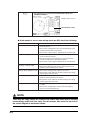
4.3
Checking Wiring
You can confirm whether wiring is properly carried out or not by viewing the
Wiring Check screen.
TOP
MENU
Displays the Measure screen.
ENTER
F1
Press the F1 key (DISPLAY CHANGE) for window callup.
Using the cursor key, select the WIRING CHECK (highlighted).
ENTER
Press the ENTER key to display the Wiring Check screen.
Judgment Result screen
Judgment result
Wiring conditions are checked by the vector diagram and
judgment results (OK/NG).
If NG is shown, check its wiring.
F3
IM CW240P-E
Press the F3 key to switch between MEASURE VALUE and
JUDGMENT RESULT.
4-3
F3
Press the F3 key to switch between MEASURE VALUE and
JUDGMENT RESULT.
Measure Value screen
Measurement values
● If the results of one or more wiring check are NG, check the following:
Results
Voltage input judgment is NG.
Measures
• Check if the voltage probes are connected properly to the
circuit under test.
• Check if the voltage probes are connected properly to the
voltage input terminals of the meter.
• Check if the voltage range is appropriate to the input level.
Current input judgment is NG.
• Check if the clamp-on current probe(s) is clamped onto the
circuit under test properly.
• Check if clamp-on current probe(s) is connected to the
current input terminal of the meter properly.
• Check if the current range is appropriate to the input level.
Phase difference judgment
(voltage - current) is NG.
• Check if the voltage phase sequence is correct.
• Check if the direction of the arrows and the phase of the
clamp-on current probe(s) are correct.
Voltage phase judgment is NG. • Check if the voltage phase sequence is correct.
• Check if the circuit under test and the setting of the wiring
system agree with each other.
Current phase judgment is NG. • Check if the direction of the arrows and the phase of the
clamp-on current probe(s) are correct.
• Check if the circuit under test and the setting of the wiring
system agree with each other.
Frequency source check is NG. • Check if the voltage input selected for the frequency source
is stable.
• Check if the voltage probes selected for the frequency
source are connected properly.
NOTE
There may be cases where the result of the check may show what is actually
correct wiring as NG and vice versa. For this reason, also check for an error in
the vector diagram or measured values.
4-4
IM CW240P-E
Chapter 5 Measurements
5. Measurements
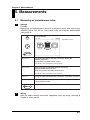
5.1
1
Measuring an instantaneous value
Settings
Example:
Measuring an instantaneous value of three-phase three-wire two-current
(3P3W2I) 200-V line (50 Hz, 120-A load) using the clamp-on probe 96030
(rating: 200 A)
TOP
MENU
Displays SETUP.
Top Menu screen
ENTER
General 1/2
Using the right and left direction cursor key, display the
General 1/2 screen.
Set up necessary items on the screen.
For details, refer to Chapter 3 in this manual.
General 2/2
Next, using the up and down direction cursor key,
display the General 2/2 screen.
Also set up necessary items on the screen.
For details, refer to Chapter 3 in this manual.
Save 1/2
Using the right and left direction cursor key, select Save 1/2 screen.
Save 2/2
Next, using the up and down direction cursor key,
select Save 2/2 screen.
ENTER
2
IM CW240P-E
This completes the settings, returning you to the Top Menu screen.
Wiring
After the above settings have been completed, carry out wiring, referring to
Chapter 4 in this manual.
5-1
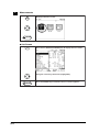
3
Measurements
TOP
MENU
Display a Measure screen.
ENTER
● List Screen
F1
Press the F1 (DISPLAY CHANGE) key to display the List screen.
Using the cursor key, select LIST (highlighted).
ENTER
5-2
Press the ENTER key to confirm it. The List screen appears.
IM CW240P-E
<Description of the List screen>
U1 to U3 : voltage rms values
Uave
: average voltage
I1 to I3 : current rms values
Iave : average current
*
I4: 4 ch. current
PA: phase angle
f: frequency
F2
F1
F3
F4
F5
Analog input
(optional)
P : active power
Q : reactive power
S : apparent power
PF : power factor
F2
LOAD CHANGE
The load changes the F2 key is pressed.
(For measurement of multiple loads)
F3
The item changes each time the F3 key is pressed:
For instantaneous value measurements, the AVE, MAX., and MIN. values
indicate the measured values of integration measurement conducted
immediately before that.
(If no integration measurement is made immediately before that,
symbol ----- appears.)
∗
IM CW240P-E
l4: 4 ch. current is displayed only when wiring are set to 1P3W3I and 3P4W4I.
5-3
● Power Screen
Press the F1 (DISPLAY CHANGE) key to display the Power screen.
F1
Using the cursor key, select POWER (highlighted).
Press the ENTER key to confirm it. The Power screen appears.
ENTER
<Description of the Power screen>
Q1 to Q3 : reactive power
Q
: total reactive power
P1 to P3 : active power
P
: total active power
S1 to S3 : apparent power
S
: total apparent power
PA1 to PA3 :phase angles
PA
:average
(phase angle)
F1
F2
F3
F4
F5
PF1 to PF3 : power factors
PF
: average (power factor)
F2
LOAD CHANGE
The load changes the F2 key is pressed.
(For measurement of multiple loads)
F3
The item changes each time the F3 key is pressed:
For instantaneous value measurements, the AVE, MAX., and MIN. values
indicate the measured values of integration measurement conducted
immediately before that.
(If no integration measurement is made immediately before that,
symbol ----- appears.)
5-4
IM CW240P-E
5.2
1
Measuring Electric Energy (Integration Measurement)
Making Settings
Example:
Measuring electric energy of three-phase three-wire two-current (3P3W2I)
200-V line (50 Hz, 120-A load) using the clamp-on probe 96030 (rating: 200 A)
General 2/2
Setting Item
Wh DISPLAY
Description (Setting value)
STANDARD
Save 1/2
Description (Setting value)
Setting Item
MEASURE START
TIME
2004/07/01 07:00
MEASURE STOP
TIME
2004/07/03 07:00
INTERVAL TIME
5 min
DATA SAVE
PC card
FILE NAME
PLANT5
Save 2/2
Description (Setting value)
Setting Item
INTEGRATE/DEMAND ON
TOP
MENU
Displays SETUP.
ENTER
General 1/2
General 2/2
Using the right and left direction cursor key, display
the General screen.
Set up necessary items on the screen.
For details, refer to Chapter 3 in this manual.
Save 1/2
Save 2/2
IM CW240P-E
Using the right and left direction cursor key, select Data Save screen.
Set up necessary items on the screen.
5-5
<General 1/2>
F1
F2
F3
F4
F5
Decimal point position
F1: The window for selecting the position of
the decimal point appears.
AUTO
000000
00000.0
0000.00
000.000
STANDARD
Using the cursor key, select the
desired position of the decimal
point (highlighted).
Press the ENTER key to confirm it.
5-6
IM CW240P-E
<Save 1/2>
F1 : MANUAL
F2 : TIME
F3: TIMER
F1 : MANUAL
F2 : TIME
F3 : JUST
Use the cursor key to
shift the digit.
F1 : +
F2 : –
F1 : PC CARD
F2 : MEMORY
F1 : PC CARD
F2 : MEMORY
F3 : PRINTER
F1
F2
F3
F4
F5
F1 : Changes a file name.
PLANT5
F1: The window for selecting the position of
the decimal point appears.
60mim
30min
15min
10min
5min
2min
1min
30sec
15sec
10sec
Using the cursor key, select
the desired data to be
saved (highlighted).
Press the ENTER key to confirm it.
IM CW240P-E
5-7
<File name change>
Cursor
Enter a file name.
Character selection area
Use the cursor key to
select characters.
F1
Enter a character to
the cursor position.
F2
Deletes one
character located to
the left of the cursor.
F3
F4
F5
Moves the cursor
to the left.
Moves the cursor
to the right.
<File name determination>
Press the ENTER key.
ENTER
This changes the file name, proceeding to the Data Save screen.
NOTE
A file name will be automatically assigned if it has not been specified:
File name: 240AMXXX (XXX: 000 to 029)
5-8
IM CW240P-E
< Save 2/2>
After settings of Save 1/2 has been completed, display the Save 2/2 screen
using up and down direction cursor key.
Set the items to be saved to ON. (OFF if not)
Use the cursor key to select items to be saved, and press the F1 key if the items
are set to ON, and the F2 key if set to OFF.
F1: ON
F2: OFF
F1 : ON
F2 : OFF
F1: CHANGE
F1
F2
F3
F4
F5
<Exiting the Save 2/2 screen>
Press the ENTER key.
ENTER
The screen returns to the Top Menu screen.
NOTE
• Check SAVE-TIME. This can confirm how long the data can be saved in the PC
card currently installed in the PC. If the SAVE-TIME is shorter than the
measurement period, delete unnecessary files in the PC card or replace the
PC card with a new one having a larger capacity.
• The measured data thus set to ON are saved to the PC card for each interval
time. If you still have other data to be saved, set the items to ON.
IM CW240P-E
5-9
2
Confirming Settings
TOP
MENU
Displays the Measure screen.
ENTER
F1
Press the F1 key (DISPLAY CHANGE) for window callup.
Using the cursor key, select INTEGRATE (highlighted).
ENTER
F4
Press the ENTER key to display the Integrate screen.
Press the F4 key to display the Setting Check screen.
Check each item is set properly before pressing the ENTER key.
This returns to the Measure (Integrate) screen.
If a set value needs to be changed, press the F1 key (SETUP).
The Setup screen appears.
Change the set value. After the setup, press the ENTER key for returning to the
Measure (Integrate) screen.
5-10
IM CW240P-E
3
Wiring
After the above settings have been completed, carry out wiring, referring to
Chapter 4 in this manual.
4
Integration Start
Check that the Integrate screen is displayed.
Press START&STOP key. Integration starts according to
the setting of the integration starting method.
START
&STOP
• STANDBY
This appears until it becomes integration start time.
• INTEG.
This appears when it becomes integration start time, starting
integration measurement.
• END
Integration stops according to the setting of the integration starting
method.
"STANDBY"
LED lights up
"INTEG."
LED lights up
Integration on
standby
Status LED
IM CW240P-E
Integration in
progress
Integration start
date & time
Integration
5-11
<Forced end>
START
&STOP
ENTER
Press START&STOP key displays the integration stop
confirmation message.
Press the ENTER key to forcibly stop integration.
"END" appears on the screen.
"INTEG."
LED lights up
"END"
LED lights up
Integration in
progress
Status LED
Integration stop
date & time
NOTE
Even if you forcibly stop integration, data before forcible stop are stored into
the PC card.
5-12
IM CW240P-E
5.3
1
Measuring Harmonics
Settings
General 2/2
Setting Item
Description (setting value)
THP measure method
THD-F (fundamental wave)
Phase angle
calculation method
Fundamental wave method
Harm. Graph Order
ALL ORD.
TOP
MENU
Displays SETUP.
ENTER
IM CW240P-E
General 1/2
General 2/2
Using right and left direction cursor key, display
the General screen.
Set up necessary items on the screen.
For details, refer to Chapter 3 in this manual.
Save 1/2
Save 2/2
Using right and left direction cursor key, select Data Save screen.
Set up necessary items on the screen.
5-13
<General 2/2>
F1 : THD-F
F2 : THD-R
F1 : FUNDAME.WAVE
F2 : U1
F1
F2
F3
F4
F5
F1 : ALL ORD.
F2 : ODD ORD.
< Save 2/2>
F1
(Change)
<Exiting the Save 2/2 screen>
Press the ENTER key.
ENTER
2
5-14
The screen returns to the Top Menu screen.
Wiring
After the above settings have been completed, carry out wiring, referring to
Chapter 4 in this manual.
IM CW240P-E
3
Measuring Harmonics
TOP
MENU
Display a Measure screen.
ENTER
F1
Press the F1 (DISPLAY CHANGE) key to display the List screen.
Using the cursor key, select HARMONIC (highlighted).
Press the right direction cursor key to move to the Harmonic window.
Select one of LIST, GRAPH and VECTOR using the up and down
direction cursor key.
ENTER
Press the ENTER key to display the Harmonic window.
(The List screen is used as an example.)
䉴 For more details, refer to the CW240 User's Manual 䉳
Chapter 6, "Configuring Settings"
Section 6.5, "Save Data Settings 2/2"
Chapter 7, "Making Measurements"
Section 7.6, "Measuring Harmonics"
IM CW240P-E
5-15
<List>
Element to be measured
Using up and down
direction cursor key,
select the desired order.
TOTAL: Total rms value*
THD : Total harmonic
distortion
F : Frequency
(frequency source)
F1
F2
F3
F4
F5
Switches the order display.
ALL ORD.
ODD ORD.
Selects the display channel
(element to be measured).
TOTAL: Total rms value*: Total rms values are displayed if the elements
to be measured are voltage (U) and current (I);
total power values are displayed if the element
to be measured is power (P).
5-16
IM CW240P-E
<Graph>
Element to
be measured
Item
Cursor measurement
Using right and left
direction cursor key,
select the desired
order.
TOTAL : Total rms value*
THD :Total harmonic
distortion
f : Frequency
(frequency source)
F2
F1
F4
F3
F5
Switches the item.
LEVEL/CONTENT/PA
Selects the display channe
(element to be measured).
<Vector>
Cursor measurement
Using right and left
direction cursor key,
select the desired order.
f:Frequency
(frequency source)
F1
F2
F2
F3
F4
F5
LOAD CHANGE
The load changes the F2 key is pressed.
(For measurement of multiple loads)
IM CW240P-E
5-17
5.4
Displaying Waveform
One of the following three screens can be displayed:
U&I WAVEFORM
1
U WAVEFORM
I WAVEFORM
Making Settings
TOP
MENU
Displays SETUP.
Top Menu screen
ENTER
General 1/2
Using right and left direction cursor key, display the
General 1/2 screen.
Set up necessary items on the screen.
For details, refer to Chapter 3 in this manual.
General 2/2
Next, using up and down direction cursor key, display the
General 2/2 screen.
Also set up necessary items on the screen.
For details, refer to Chapter 3 in this manual.
Save 1/2
Using right and left direction cursor key, select Save 1/2 screen.
Save 2/2
Next, using up and down direction cursor key, select
Save 2/2 screen.
Volt. Quality
Using the cursor key, select VOLT. QUALITY.
ENTER
2
5-18
This completes the settings, and return to the Top Menu screen.
Wiring
After the above settings have been completed, carry out wiring, referring to
Chapter 4 in this manual.
IM CW240P-E
3
Displaying Waveforms
TOP
MENU
Displays the Measure screen.
ENTER
F1
Press the F1 key (DISPLAY CHANGE) for window callup.
Using the cursor key, select WAVEFORM (highlighted).
Press the right direction cursor key to move to the Waveform window.
Using up and down direction cursor key to select one of VOLT. &
CURR., VOLTAGE and CURRENT .
ENTER
Press the ENTER key to display the Waveform window.
The VOLT. & CURR. (U&I) screen is used as an example.
䉴 For more details, refer to the CW240 User's Manual 䉳
Chapter 6, "Configuring Settings"
Subsection 6.5.4, "Waveform Data"
Chapter 7, "Making Measurements"
Section 7.7, "Displaying Waveform"
IM CW240P-E
5-19
F1
F2
F3
F4
F5
Changes the magnification of
the vertical axis of current.
Changes the magnification of
the vertical axis of voltage.
Changes the CH number to be displayed.
(The CH number differs depending on setting of wiring.)
<Vertical axis>
• The display range of the vertical axis is determined on the basis of the
measurement range set.
• U ZOOM and I ZOOM allow you to change the magnification (scaling) of the
vertical axis.
1 → 2 → 5 → 10 → 20 → 1/3 → 1/2
<To switch a waveform screen>
Using up and down direction cursor key, switch the waveform screen.
U&I WAVEFORM
5-20
U WAVEFORM
I WAVEFORM
IM CW240P-E
5.5
1
Measuring Voltage Quality (Voltage Fluctuation)
Settings
Example:
Standard voltage: 100 V; Voltage swell: 120%; Voltage dip: 90%; Interruption:
10%; Hysteresis: 1%
Save 1/2
Description
(Setting value)
Setting Item
Measure Start
TIME
2004/07/01 07:00
TIME
Measure Stop
2004/07/03 07:00
Interval Time
5 min
Data Save
PC card
Volt. Quality
Description
(Setting value)
Setting Item
Volt. Quality measurement
ON (performs voltage
quality measurement)
Standard Voltage
100V
Threshold Value Voltage dip
110%
Voltage swell
90%
Instantaneous
10%
voltage interruption
Hysteresis
IM CW240P-E
1%
5-21
TOP
MENU
Displays the Measure screen.
Top Menu screen
ENTER
General 1/2
Using right and left direction cursor key, display the
General 1/2 screen.
Set up necessary items on the screen.
For details, refer to Chapter 3 in this manual.
General 2/2
Next, using up and down direction cursor key, display the
General 2/2 screen.
Also set up necessary items on the screen.
For details, refer to Chapter 3 in this manual.
Save 1/2
Using right and left direction cursor key, select Save 1/2 screen.
Save 2/2
Next, using up and down direction cursor key, select
Save 2/2 screen.
Volt. Quality
Using the cursor key, select VOLT. QUALITY.
ENTER
5-22
This completes the settings, and return to the Top Menu screen.
IM CW240P-E
<Save 1/2>
F1: MANUAL
F2: TIME
F3: JUST
Use the cursor key to
shift the digit.
F1: +
F2: –
F1: PC CARD
F2: MEMORY
F1
F2
F4
F3
F5
F1: MANUAL
F2: TIME
F3: TIMER
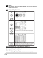
<Volt. Quality>
F1: ON
F2: OFF
F1
F2
F3
F4
F1: The CHANGE window appears.
240V
F5
Use the cursor key to
shift the digit.
F1: +
F2: –
230V
220V
Setting Range
208V
SWELL : 0 to 200%
200V
DIP
120V
INTERRUPTION : 0 to 100%
110V
HYSTERESIS
101V
100V
: 0 to 100%
: 0 to 10%
Using the cursor key, select
the desired data (highlighted).
Press the ENTER key to confirm it.
IM CW240P-E
5-23
2
Wiring
After the above settings have been completed, carry out wiring, referring to
Chapter 4 in this manual.
3
Voltage Quality Measurement
TOP
MENU
Displays the Measure screen.
ENTER
F1
Press the F1 key (DISPLAY CHANGE) for window callup.
ENTER
Using the cursor key, select VOLT. QUALITY (highlighted).
ENTER
START
&STOP
The Volt. Quality screen appears.
Press the START&STOP key. Start integration
according to the setting of the integration starting method.
"STANDBY" appears until it becomes integration start time.
䉴 For more details, refer to the CW240 User's Manual 䉳
Chapter 6, "Configuring Settings"
Subsection 6.7, "Voltage Quality Settings"
Chapter 7, "Making Measurements"
Section 7.8, "Measuring Voltage Quality
(Voltage Dip, Voltage Swell, or Instantaneous Interruption)"
5-24
IM CW240P-E
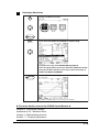
● Voltage Quality Measurement
In this section, voltage dip, voltage swell or instantaneous interruption are
measured and displayed.
Input channel
Date and time of
occurrence
I : Occurrence of an item under test
O: End of detection
Item
Voltage (rms)
Period of occurrence
of the item under test
F1
F2
F3
F4
F5
Saves the data of voltage quality
Selects one of the following items:
Use up and down direction
cursor key to scroll the page.
• Voltage swell (Swe)
• Voltage dip (Dip)
• Instantaneous voltage interruption
(Int)
• All items
● Stopping Integration Measurement
Integration stops according to the setting of the integration starting method.
("END" appears when it becomes integration stop time.)
As soon as integration stops, voltage quality data is written to the PC card.
● Forcibly Stopping Integration Measurement
If you want to stop integration measurement before it becomes integration stop
time thus set, press the START&STOP key while integration is in progress.
NOTE
Even if you forcibly stop integration, data before forcible stop are stored into
the PC card.
IM CW240P-E
5-25
Chapter 6 Troubleshooting
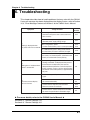
6. Troubleshooting
This chapter describes how to handle problems that may arise with the CW240.
If an error message has been displayed on the display screen, refer to Section
16.2, "Error Message Content and Actions" of the CW240 User's Manual.
Symptom
Things to Check
When using AC power
• Confirm that the power cord is connected to the
outlet correctly.
3.2.1
• Confirm that the power supply is within the
allowable power supply voltage range.
3.2.1
1)
When using battery power
Nothing is displayed when
• Confirm that the battery case is correctly installed.
the power switch is turned ON.
• If a NiMH battery pack is being used, confirm
that the battery has been sufficiently charged.
2)
Setting data is initialized when
power is turned OFF.
Reference
Section
3.2.2
3.2.3
3.2.3
• If an alkaline dry cell is being used, confirm that
the battery has not dissipated. (Confirm that the
battery is installed with correct polarity.)
3.2.2
• If the opening messages "RTC Initialized" and
"Settings Initialized" are displayed when power is
turned ON, the backup battery has become
dissipated. Backup batteries cannot be replaced
by the customer. Contact a service representative.
The lifetime of the backup battery is approximately
10 years.
3.6
• Check for the possibility of noise on the input
signal.
3)
The measurement display
value is incorrect.
• Confirm that the measurement probe and clamp
are connected correctly.
3.3
3.4
• Confirm that the frequency measurement
element has been set correctly.
6.3.2
6.3.3
• Confirm that the ambient temperature/humidity
are within the specification's allowable range.
4.2
䉴 For more details, refer to the CW240 User's Manual 䉳
Section 6.2, "General Settings 1/2"
Section 6.3, "General Settings 2/2"
IM CW240P-E
6-1
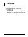
Symptom
4)
Key operation cannot be done.
5)
Saving and writing to internal
memory cannot be done.
6)
Saving and writing to the
PC card cannot be done.
7)
Communication cannot be done
through the RS-232 interface.
8)Printing cannot be done.
• Confirm that key lock is not displayed at the
upper right of the display area.
15.3
• Turn the power OFF then ON again. The problem
may be resolved in the opening self-test.
3.6
• It is possible that a power supply error, etc.,
occurred while the internal memory was being
accessed.
Format the internal memory in the file processing
mode. Data saved in the internal memory will be
lost.
9.4
• Confirm that the PC card has been inserted
correctly.
11.2
• Confirm that the PC card has been formatted.
9.4
• Confirm that the capacity of the PC card has not
been exceeded.
11
• Confirm that the communication parameters of
the CW240 and the controller, etc., match.
6.6
• Confirm that the specifications of the cables
connecting the CW240 and the controller, etc.,
are suitable for the purpose.
10.2
• Confirm that printer power is ON.
(Refer to the printer's instruction manual.)
10.3
• Confirm that connection cable specifications
match.
10.3
• Confirm that connection cables are connected
correctly.
10.3
• Confirm that the communication parameters of
this device and the printer match.
10.3
• Confirm that the print media has been set
correctly.
9)
An error occurs in the opening
message.
6-2
Reference
Section
Things to Check
• This is a hardware error. Contact to your local
service representative.
–
3.6
IM CW240P-E
Chapter 7 Memory Capacity (for Reference)
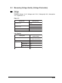
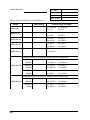
7. Memory Capacity (for Reference)
For saving all items of normal measurement data, electric energy/demand
measured data, all items of harmonic measured data, waveform data and
voltage quality measured data
Wiring
No. of Data Items
1P2W
1P3W
4 loads 2 loads
5624
5052
1P3W3I
3758
3P3W2I 3P3W3I,
2 loads 3P4W
6888
4390
3P4W4I
5002
3P3W+
1P3W
7504
PC card
1min
17hours 19hours 26hours 14hours 22hours 19hours 13hours
(64MB)
60min
44days
49days
65days
35ays
56days
49days
Internal
1min
12min
13min
19min
8min
16min
13min
Memory
60min
12hours 13hours 19hours
8hours 16hours 13hours
32days
7min
7hours
1min, 60min : Interval time
䉴 For more details, refer to the CW240 User's Manual 䉳
Section 8.3, "Memory (Reference)"
IM CW240P-E
7-1
Chapter 8 Check Sheets
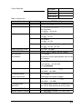
8. Check Sheets
How to use these check sheets
This Quick Setup Manual comes with check sheets so that you can accurately
and effectively carry out on-site measurements and settings. Please make use
of these sheets, describing necessary setting items in advance.
Description on check sheets
• Setting of the current range (A range) varies depending on the clamp-on
current probe to be used.
• Voltage/current input indication varies depending on the setting of the wiring
and load.
• The shaded mark such as 150V indicates the default setting value upon
system reset or when shipped from the factory.
IM CW240P-E
8-1
Check Sheet No.
File name:
Site name:
Prepared by:
Date issued:
Table 1: General 1/2
User setting
Item
Wiring
CW240 setting
<1> Change
If you would like to change wiring,
select one of the following items:
Number of Load
Load
3P3W+1P3W
3P3W21
3P4W4I
1P3W3I
3P4W
1P3W
3P3W3I
1P2W
For 1P3W or 3P3W2I:
<1> Load 1 <2> Load 2
For 1P2W:
<1> Load 1 <2> Load 2
<3> Load 3 <4> Load 4
Wiring: 3P3W + 1P3W
Load at 1P3W
U range (voltage range)
For 3P3W + 1P3W:
<1> R-S <2> S-T <3> T-R
Voltage inputs (U1-U3) differ depending on the setting of
the wiring and load.
<1> 150V <2> 300V 4
Example
Voltage
U1
U range
300
VT ratio
0001.00
U1
U2
<3> 600V <4> 1000V
V
U3
VT ratio
8-2
1.00
0.01 to 9999.99
IM CW240P-E
Check Sheet No.
File name:
Site name:
Prepared by:
Date issued:
Table 2: General 1/2
Item
CW240 setting
User setting
A range (current range)
Current input channels (CH) differ depending on the setting
of the wiring and load.
CH1
A Setting of the current range (A range)
Example
Current
CH1
CH2
varies depending on the clamp-on current
A probe to be used.
A range
500A
CH3
A
CT ratio
0001.00
Clamp-on
current probe
96032
CH4
A
Refer to Table 3. *1
CT ratio
1.00
0.01 to 9999.99
Clamp-on probe *1
<1> Change
If you would like to change the probe,
select one of the following probes:
IM CW240P-E
96035-2 (300A)
96032
96035-1 (3000A)
96031
96034-3 (1000A)
96030
96034-2 (2000A)
96033
96034-1 (3000A)
96036
8-3
Check Sheet No.
File name:
Site name:
Prepared by:
Date issued:
Table 3: Types of Clamp-on Current Probes *1
Model
96036(2 A)
–
–
96033(50 A)
–
96030(200 A)
–
96031(500 A)
–
96032(1000 A)
–
User setting
Current range (A range)
<1> 200 mA
<2> 500 mA
<3> 1 A
<4> 2 A
<1> 5 A
<2> 10 A
<3> 20A
<4> 50 A
<1> 20 A
<2> 50 A
<3> 100 A
<4> 200 A
<1> 50 A
<2> 100 A
<3> 200 A
<4> 500 A
<1> 200 A
<2> 500 A
<3> 1000 A
Using the switch on a clamp-on probe to select current range
96034(3000 A)
96034_1
<1> 300 A
<2> 750 A
(3000A)
<3> 1500 A
<4> 3000 A
96034_2
<1> 200 A
<2> 500 A
(2000A)
<3> 1000 A
<4> 2000 A
96034_3
<1> 100 A
<2> 200 A
(1000A)
<3> 500 A
<4> 1000 A
Using the switch on a clamp-on probe to select current range
96035(3000 A)
96035_1
<1> 300 A
<2> 750 A
(3000A)
<3> 1500 A
<4> 3000 A
<1> 30 A
<2> 75 A
<3> 150 A
<4> 300 A
96035_2
(300A)
8-4
IM CW240P-E
Check Sheet No.
File name:
Site name:
Prepared by:
Date issued:
Table 4: General 2/2
Item
User setting
CW240 setting
VAR METHOD
<1> ON <2> OFF
SAMPLING METHOD
<1> PLL synchronization <2> Fixed clock
For fixed clock:
<1> 50 Hz <2> 60 Hz
FREQUENCY SOURCE
For 1P3W or 1P3W3I:
<1> U1 <2> U2
For 3P3W2I:
<1> U1 <2> U3
For 3P3W3I, 3P4W, 3P4W4I, or 3P3W + 1P3W:
<1> U1 <2> U2 <3> U3
ZERO CROSS FILTER
<1> ON <2> OFF
AVERAGE TIMES
<1> 1 <2> 2 <3> 5 <4> 10 <5>20
Wh DISPLAY/
<1> Change
INTEGRATE
If selected: Decimal point position and unit can
be changed.
(Decimal point position)
<1> AUTO <2> 000000 <3> 00000.0
<4> 0000.00 <5> 000.000
<6> STANDARD
(Unit)
<1> mWh <2> Wh <3> kWh
<4> MWh <5> GWh
E.ENEGRY/DEM.
<1> Change
within Interval time
If selected: Unit can be changed.
(Unit)
<1> mWh
<2> Wh
<4> MWh
<5> GWh
THD MEASURE
<1> THD-F With reference to fundamental wave
METHOD
<2> THD-R With reference to all rms values
<3> kWh
PA CALC. METHOD
<1> Fundamental wave <2> U1
HARM. GRAPH ORDER
<1> ALL ORD. (1st-50th) <2> ODD ORD.
IM CW240P-E
8-5
Check Sheet No.
File name:
Site name:
Prepared by:
Date issued:
Table 5: Save 1/2
Item
User setting
MEASURE START
<1> MANUAL <2> TIME <3> JUST
STOP
TIME
TIMER
SAVE
CW240 setting
<1> MANUAL <2> TIME <3> TIMER
Start date
Stop date
Start time
Stop time
________ (hh:mm:ss) to ________ (hh:mm:ss)
INTERVAL
<1> Change
TIME
If selected: Select one of the following items:
Min
Sec
60 min
30 min
30 sec
15 min
15 sec
10 min
10 sec
5 min
5 sec
500 msec
2 min
2 sec
200 msec
1 min
1 sec
100 msec
1 wave
DATA SAVE
<1> PC card <2> Internal memory
HARD COPY
<1> PC card <2> Internal memory
<3>Printer
FILE NAME
<1> Change
If selected: Enter a file name.
8-6
IM CW240P-E
Check Sheet No.
File name:
Site name:
Prepared by:
Date issued:
Table 6: Save 2/2
Item
User setting
CW240 setting
Electric Energy data
<1> ON Saves data.
Demand data
<2> OFF Does not save data.
WAVEFORM data
<1> ON Saves data.
<2> OFF Does not save data.
Normal measurement data
<1> ON Saves data.
<2> OFF Does not save data.
Harmonic data MEAS.
<1> ON Saves data.
<2> OFF Does not save data.
Detailed items of Harmonic data
<1> Change
MEAS. DETA.
If selected: The Detail screen appears.
Refer to Table 7 for details.
Common to normal
INST.
<1> ON <2> OFF
measurement and
AVE
<1> ON <2> OFF
harmonic
MAX.
<1> ON <2> OFF
measurement
MIN.
<1> ON <2> OFF
IM CW240P-E
8-7
Check Sheet No.
File name:
Site name:
Prepared by:
Date issued:
Table 7: Save 2/2
Item
LOAD
ELEMENT
User setting
CW240 setting
Displays the number of loads.
LOAD 1
<1> ON <2> OFF
LOAD 2
<1> ON <2> OFF
LOAD 3
<1> ON <2> OFF
LOAD 4
<1> ON <2> OFF
Element display varies depending on the setting of the wiring.
U1
<1> ON <2> OFF
U2
<1> ON <2> OFF
U3
<1> ON <2> OFF
P
<1> ON <2> OFF
I1
<1> ON <2> OFF
I2
<1> ON <2> OFF
I3
<1> ON <2> OFF
I4
<1> ON <2> OFF
LEVEL
<1> ON <2> OFF
CONTENT
<1> ON <2> OFF
HARM. PA
<1> ON <2> OFF
TOTAL VAL
<1> ON <2> OFF
THD
<1> ON <2> OFF
8-8
IM CW240P-E
Check Sheet No.
File name:
Site name:
Prepared by:
Date issued:
Table 8: Harmonic Output Order Setup
Item
User setting
OUTPUT ORDER
CW240 setting
<1> Saves ALL ORD. (1st to 50th)
<2> Saves ODD ORD.
<3> Saves EVEN ORD.
<4> Allows you to select harmonic orders
individually.
<1> ON <2> OFF
An asterisk (*) is displayed for a selected order number.
01
02
03
04
05
06
07
08
09
10
11
12
13
14
15
16
17
18
19
20
21
22
23
24
25
26
27
28
29
30
31
32
33
34
35
36
37
38
39
40
41
42
43
44
45
46
47
48
49
50
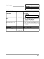
Table 9: Communication
Item
User setting
CW240 setting
RS-232 CONNECT
<1> Printer <2> PC
BAUD RATE
<1> Change
If selected: Select one of the
following items:
DATA LENGTH
<1> 7
38400 bps
4800 bps
19200 bps
2400 bps
9600 bps
1200 bps
<2> 8
PARITY
<1> EVEN <2> ODD <3> NONE
STOP BIT
<1> 1
FLOW CONTROL
<1> OFF/OFF <2> XON/XON
<2> 2
<1> XON/RS
IM CW240P-E
<2> CS/RS
8-9
Check Sheet No.
File name:
Site name:
Prepared by:
Date issued:
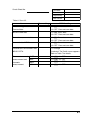
Table 10: Voltage Quality
Item
VOLT. QUALITY MEAS.
User setting
CW240 setting
<1> ON Measures voltage quality.
<2> OFF Does not measure voltage quality.
STANDARD VOLTAGE
<1> Change
If selected: Select one of the following items:
1000 V
277 V
120 V
600 V
240 V
110 V
480 V
230 V
101 V
380 V
220 V
100 V
346 V
208 V
202 V
200 V
THRESHOLD
VALUE
SWELL
110%
0 to 200%
DIP
90%
0 to 100%
INTERRUPTION
10%
0 to 100%
HYSTERESIS
Percent indication with respect to
standard voltage
(common to voltage swell, voltage dip,
voltage interruption)
1%
8-10
0 to 10%
IM CW240P-E
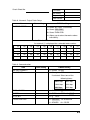
Check Sheet No.
File name:
Site name:
Prepared by:
Date issued:
Table 11: Hardware
Item
User setting
LANGUAGE
CW240 setting
<1> Change
If selected:
ENGLISH
<1> ON Generates a beep each time an
BEEP
operation key is pressed.
<2> OFF Turns off the beep.
BACKLIGHT AUTO OFF
<1> ON Automatically turns off backlight.
<2> OFF Does not automatically turn off
backlight.
LCD CONTRAST
Sets LCD contrast (1 to 8).
ID NUMBER
001
DATE AND TIME
Year/Month/
001 — 999
Sets date and time (accurate time entry).
Hour/Min/Sec
IM CW240P-E
8-11
YOKOGAWA M&C CORPORATION
International Sales Dept.
2-9-32 Nakacho, Musashino-shi, Tokyo, 180-8750 Japan
Phone: 81-422-52-5716 Facsimile: 81-422-55-8954
YOKOGAWA CORPORATION OF AMERICA (U.S.A.)
Phone: 1-770-253-7000 Facsimile: 1-770-251-2088
YOKOGAWA EUROPE B. V. (THE NETHERLANDS)
Phone: 31-334-64-1611 Facsimile: 31-334-64-1610
YOKOGAWA ENGINEERING ASIA PTE. LTD. (SINGAPORE)
Phone: 65-6241-9933 Facsimile: 65-6241-2606
YOKOGAWA AMERICA DO SUL S. A. (BRAZIL)
Phone: 55-11-5681-2400 Facsimile: 55-11-5681-1274
YOKOGAWA MEASURING INSTRUMENTS KOREA CORPORATION (KOREA)
Phone: 82-2-551-0660 to -0664 Facsimile: 82-2-551-0665
YOKOGAWA AUSTRALIA PTY. LTD. (AUSTRALIA)
Phone: 61-2-9805-0699 Facsimile: 61-2-9888-1844
YOKOGAWA INDIA LTD. (INDIA)
Phone: 91-80-2227-1513 Facsimile: 91-80-2227-4270
YOKOGAWA SHANGHAI TRADING CO., LTD. (CHINA)
Phone: 86-21-6880-8107 Facsimile: 86-21-6880-4987
YOKOGAWA MIDDLE EAST E. C. (BAHRAIN)
Phone: 973-358100 Facsimile: 973-336100
LTD. YOKOGAWA ELECTRIC (RUSSIAN FEDERATION)
Phone: 7-095-737-7868 Facsimile: 7-095-737-7869
KIM3E-2004.7