1
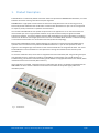
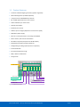
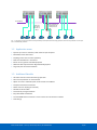
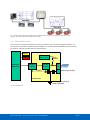
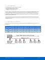
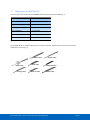
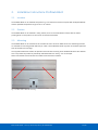
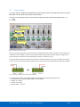
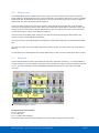
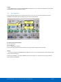
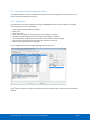
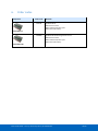
ProfiHub B5+R User manual Safety Guidelines This manual contains notices which you should observe to ensure your own personal safety, as well as to protect the product and connected equipment. These notices are highlighted in the manual by a warning sign and are marked as follows according to the level of danger: Draws your attention to important information on handling the product, a particular part of the documentation or the correct functioning of the product. Warning This device and its components may only be used for the applications described in this manual and only in connection with devices or components that comply with PROFIBUS and an RS 485 interface. This product can only function correctly and safely if it is transported, stored, set up, installed, operated and maintained as recommended. Qualified Technicians Only qualified technicians should be allowed to install and work with this equipment. Qualified technicians are defined as persons who are authorized to commission, to ground, to tag circuits and systems in accordance with established safety practices and standards. It is recommended that the technicians carry a Certified PROFIBUS Installer or Certified PROFIBUS Engineer certificate. Disclaimer of Liability We have checked the contents of this manual as much as possible. Since deviations cannot be precluded entirely, we cannot guarantee full agreement. However, the content in this manual is reviewed regularly and any necessary corrections included in subsequent editions. Suggestions for improvement are welcomed. Copyright © 2014 PROCENTEC All rights reserved. No part of this publication may be reproduced, stored in a retrieval system, or transmitted, in any form or by any means, electronic, mechanical, photocopying, recording or otherwise, without the prior written permission of the publisher. Manual-B5+R-EN – v3.1.0 | 06 January 2015 | © PROCENTEC 2/60 Important information Purpose of the Manual This manual explains how to put the ProfiHub B5+R into operation. Recycling and Disposal The parts of the ProfiHub can be recycled. For further information about environment-friendly recycling and the procedure for disposing your old equipment, please contact: PROCENTEC Klopperman 16 2292 JD WATERINGEN The Netherlands Tel.: +31-(0)174-671800 Fax: +31-(0)174-671801 Email: [email protected] Document Updates You can obtain constantly updated information on PROCENTEC products on the Internet at www.procentec.com You can also contact PROCENTEC Customer Support: • by phone at +31-(0)174-671800 • by fax at +31-(0)174-671801 • by email at [email protected] Manual-B5+R-EN – v3.1.0 | 06 January 2015 | © PROCENTEC 3/60 Important notices WARNING When the product is in use at an ambient temperature of 63 degrees Celsius or 145 degrees Fahrenheit, the housing of the ProfiHub B5+ will be hot. Do not touch the housing! At normal operating temperatures of 25 degrees Celsius, the temperature of the housing will not exceed 35 degrees Celsius. WARNING When the product is in use at an ambient temperature of 63 degrees Celsius or 145 degrees Fahrenheit, the housing of the ProfiHub B5+ will be hot. Do not touch wires which are in contact with the housing! WARNING When the product is in use at an ambient temperature of 63 degrees Celsius or 145 degrees Fahrenheit, the housing of the ProfiHub B5+ will be hot. Use wires suitable for these temperatures! HOT HOUSING warning located on the side of the housing. Make sure this warning is visible after wall installation. UL certification demands the warning to be visible during operation. To comply with UL certification regulations (UL60950-1) the power supply must be a Limited Power Source (LPS) or NEC Class 2 or CEC Class 2 that cannot exceed 100VA. According to UL60950-1, if a copper PROFIBUS cable is used outside, it is required to install surge protection that is suitable for PROFIBUS. To comply with UL certification regulations the ProfiHub B5+ is to be used on altitudes under 2000 m. Manual-B5+R-EN – v3.1.0 | 06 January 2015 | © PROCENTEC 4/60 Contents Important information ............................................................................................................................................ 3 Important notices ................................................................................................................................................... 4 Contents .................................................................................................................................................................. 5 1. 2. 3. Product Description ........................................................................................................................................ 7 1.1 Product Features.................................................................................................................................. 8 1.2 Application areas ................................................................................................................................. 9 1.3 Additional Benefits .............................................................................................................................. 9 1.4 Channel Structure .............................................................................................................................. 10 1.5 Grounding System.............................................................................................................................. 11 1.6 Cable lengths for PROFIBUS DP ......................................................................................................... 11 1.7 Cable types for PROFIBUS DP ............................................................................................................ 12 1.8 Status LEDs ......................................................................................................................................... 13 1.9 Comparison table ............................................................................................................................... 14 Installation Instructions ProfiHub B5+R ........................................................................................................ 15 2.1 Location ............................................................................................................................................. 15 2.2 Position .............................................................................................................................................. 15 2.3 Mounting ........................................................................................................................................... 15 2.4 Power Supply ..................................................................................................................................... 16 2.5 Grounding of the power .................................................................................................................... 17 2.6 Relay contact ..................................................................................................................................... 18 2.7 Backbone ........................................................................................................................................... 18 2.8 Spur Segments ................................................................................................................................... 19 2.9 Termination ....................................................................................................................................... 20 2.10 Baudrate switch ................................................................................................................................. 21 2.11 Channel Redundancy ......................................................................................................................... 22 Diagnostics Device ........................................................................................................................................ 23 3.1 Setting up the Diagnostics Device ...................................................................................................... 24 3.1.1 Enabling the Diagnostics Device ........................................................................................................ 24 3.1.2 Changing the default PROFIBUS address ........................................................................................... 24 3.1.3 GSD file .............................................................................................................................................. 25 3.2 Configuring the Diagnostic Device ..................................................................................................... 25 3.2.1 Info data (mandatory module) .......................................................................................................... 25 3.2.2 Alarm Confirmation ........................................................................................................................... 25 3.2.3 Redundant Status .............................................................................................................................. 25 3.2.4 Baudrate Status ................................................................................................................................. 26 3.2.5 Relay Status ....................................................................................................................................... 26 3.2.6 Power Status ...................................................................................................................................... 26 Manual-B5+R-EN – v3.1.0 | 06 January 2015 | © PROCENTEC 5/60 3.2.7 Termination Status ............................................................................................................................ 27 3.2.8 Channel Status ................................................................................................................................... 27 3.2.9 Livelist Status ..................................................................................................................................... 27 3.2.10 Statistics (Short Format, Long Format ) ............................................................................................. 28 3.3 Parameterizing the Diagnostic Device ............................................................................................... 30 3.3.1 Diagnostics ......................................................................................................................................... 30 3.3.2 Statistics ............................................................................................................................................. 31 3.3.3 Extended Diagnostics on Events change ............................................................................................ 31 3.3.4 Extended Diagnostics on Statistics change ........................................................................................ 32 3.3.5 Alarm Relay on Events change ........................................................................................................... 33 3.3.6 Alarm relay on Statistics change ........................................................................................................ 33 3.3.7 Changing the Diagnostics duration/timeout...................................................................................... 34 3.3.8 Changing the Device Lost timeout ..................................................................................................... 34 3.3.9 Changing the data format .................................................................................................................. 35 3.4 ProfiTrace plugin for the Diagnostic Device ....................................................................................... 35 3.4.1 Installing the Plugin ........................................................................................................................... 35 3.4.2 Using the Plugin ................................................................................................................................. 37 4. Technical Data ProfiHub B5+R / B5+RD ........................................................................................................ 38 5. Sales offices and Distributors ........................................................................................................................ 40 6. Order codes ................................................................................................................................................... 44 7. Glossary ......................................................................................................................................................... 45 8. Certificates .................................................................................................................................................... 48 9. Revision History............................................................................................................................................. 56 10. Notes ............................................................................................................................................................. 57 11. Other PROCENTEC products.......................................................................................................................... 58 12. About PROCENTEC ........................................................................................................................................ 59 Manual-B5+R-EN – v3.1.0 | 06 January 2015 | © PROCENTEC 6/60 1. Product Description ProfiHub B5+R is an advanced, flexible and robust network component for PROFIBUS DP installations, to create backbone structures and long multi-device star/tree segments. PROFIBUS DP is a high speed communication bus that must comply with strict rules concerning spur lines, because of possible reflections that could lead to communication disturbances. If spur lines or star segments are required, costly investments in repeaters have to be done. The innovative ProfiHub B5+R is the perfect component for such applications. It is an economic solution to realise reliable spur lines in high speed DP networks. They have the functionality of 5 galvanic isolated transparent repeaters. This allows network structures with extended spur lines that individually can handle a maximum of 31 devices and a length equal to the main bus. The ProfiHub B5+R refreshes a received message on one Channel and transfers it to all the other Channels (chicken foot topology). Because the ProfiHub B5+R creates isolated segments, the devices can now be removed and added during operation. Also most electrical bus problems and EMC disturbances in a spur do not spread to the other segments. The intelligent logic and isolation circuits of the ProfiHubs do not change the bit width. This means the ProfiHubs do not have limitations in serial placement. The logic also detects the transmission speed automatically. To assist the installation work, termination is integrated and can be switched on/off. The grounding concept is also selectable: direct or capacitive grounding. The ProfiHubs are powered by a 10 to 24 DC Voltage. For troubleshooting, maintenance and commissioning the ProfiHubs are equipped with LEDs on the outside, which indicate the status of each Channel (Data and Error). If bus redundancy is enabled, 2 segments will form a redundant pair which is completely compatible with the ABB RLM01. An alarm contact is linked to events based on the status of the power supply and the bus redundancy status. Fig. 1 - ProfiHub B5+R Manual-B5+R-EN – v3.1.0 | 06 January 2015 | © PROCENTEC 7/60 1.1 Product Features • 5 Galvanic isolated outgoing channels (repeater segments) • Advanced Diagnostic capabilities (B5+RD) • Transparent for all PROFIBUS DP protocols • DP - RS 485 specifications for each channel • Cable redundancy for channel 4+5 • 9.6 Kbps to 12 Mbps. • 31 devices per channel • 1200 m spur line length (depends on transmission speed) • Redundant power supply • No limit in serial placement or cascading of ProfiHubs • Alarm contact, with manual reset button • No address required (except for the B5+RD option) • Integrated termination facilities (switches) • Configurable grounding system (direct or capacitive) • IP 20 classification • Increased temperature range • DNV / offshore Certification • UL approvals Alarm contact Intelligent Internal Backbone Main Bus C1 C2 C3 C4 C5 Power supply 1 Power supply 2 Main bus In Channel 1 to 5 Main bus Out Fig. 2 - ProfiHub connections Manual-B5+R-EN – v3.1.0 | 06 January 2015 | © PROCENTEC 8/60 DP backbone Each spur line can be 200m at 1,5 Mbps Wiring problems do not spread to the other spur lines Fig. 3 - Long spur lines to instruments and the possibility to remove/insert them during operation. Short circuit protection on each spur line is automatically provided. 1.2 Application areas • Dynamic spur lines to actuators, flow meters and pH analyzers • Removable drives and motors • Pull/Plug motor control centers (drawers) • Roof mounted devices in tank farms • Barrier for non galvanic isolated equipment • Networks with requirement for High Availability/uptime • Large star/tree structured networks 1.3 Additional Benefits • Hot slave insertion and removal during operation • Short circuit protection on each Channel • Option to create a redundant path to other Hubs or ComBricks • Compact and robust construction • Status and error display (per Channel) • Suitable for all DP cables • Conveniently arranged networks • Easy extendable installations • On-board DB9 female connector on each channel for maintenance activities • Cost Savings Manual-B5+R-EN – v3.1.0 | 06 January 2015 | © PROCENTEC 9/60 Fig. 4 - Because of the isolation and intelligence the ProfiHub provides, it can be used as a barrier for electrically sensitive segments. This keeps the backbone and other Channels clean. 1.4 Channel Structure Each Channel is electrically isolated and internally connected to the transparent intelligent backbone. The termination is switchable and powered by the ProfiHub. The shielding of the PROFIBUS cable can be directly grounded or indirectly grounded (see the next paragraph). RX-OK Powered Termination ERROR Intelligent Backbone Isolation Circuit Term. Switch RS 485 Circuit A B DGND I C Indirect grounding C Isolated Area To direct grounding of other Channels Fig. 5 - Channel structure Manual-B5+R-EN – v3.1.0 | 06 January 2015 | © PROCENTEC 10/60 1.5 Grounding System The ProfiHub B5+R can be grounded by 3 methods: 1. Direct grounding on the Ground Rail 2. Indirect grounding (through a capacitor) 3. Combination of direct and indirect. The power supply must be grounded directly on the Ground Rail. The shielding of the PROFIBUS cables can be directly or indirectly grounded. If you do not want to ground all or some cables to the common ground, i.e. compensating current, the cable shielding must be connected to pin ‘I’ which stands for Indirect grounding. A capacitor with a parallel high value resistor will separate the 2 potentials ( Fig. 5), ensuring protection of the signal against non-DC disturbances. If by accident on 1 channel the Direct Grounding is connected with the Indirect Grounding, the connection to the Direct Grounding bypasses the capacitor in the Indirect Ground connection. The current on the shield will flow to Direct Ground. 1.6 Cable lengths for PROFIBUS DP The cables on the Channels and the Main-Channel must comply with the PROFIBUS DP cable specifications for RS 485 (Fig. 6). Fig. 6 - Cable lengths for PROFIBUS DP Manual-B5+R-EN – v3.1.0 | 06 January 2015 | © PROCENTEC 11/60 1.7 Cable types for PROFIBUS DP The cable type must comply with the PROFIBUS DP cable specifications for RS 485 (Fig. 7). Parameter Value Wires 2 (twisted) Impedance 135 .. 165 Ohm at 3 to 20 MHz Capacity < 30 pF/m Loop resistance < 110 Ohm/km Wire diameter > 0.64 mm Wire area > 0.32 mm2 Fig. 7 - PROFIBUS DP cable specifications The ProfiHub B5+R can handle cables based on multiple protection sheaths with an overall cable diameter between 6 to 12 mm (Fig. 8). Robust cable Hybrid cable Trailing cable Food cable Festoon cable Flexible cable Shipboard cable FRNC cable Fig. 8 - Cables with different protection sheaths. Manual-B5+R-EN – v3.1.0 | 06 January 2015 | © PROCENTEC 12/60 1.8 Status LEDs The Status LEDs on the ProfiHub are very useful for diagnostics. POWER 1 / 2 READY Main RX-OK Main ERROR Channel RX-OK Channel ERROR INT. TERM OFF Blinking ON Power is not switched Power supply not Power supply OK. on or an internal failure stable, redundant power supply interrupted or an internal failure Power is not switched Trying to detect the The transmission on or an internal failure transmission speed, but has not locked it yet speed has been detected. No communication 1 or more devices 1 or more devices detected on the MainChannel communicating on the Main-Channel communicating on the Main-Channel No problem has been Problem in the cabling Problem in the cabling detected has been detected (Main Channel) has been detected (Main Channel) There is no 1 or more devices 1 or more devices communication detected (on this Channel) communicating (on this Channel) communicating (on this Channel) No problem has been Problem in the cabling Problem in the cabling detected has been detected (on this Channel) has been detected (on this Channel) Termination for this channel is OFF Internal failure Termination for this channel is ON Manual-B5+R-EN – v3.1.0 | 06 January 2015 | © PROCENTEC 13/60 1.9 Comparison table ProfiHub A5 ProfiHub B5 ProfiHub B5+R / B5+RD Area IP 65 IP 20 IP 20 Redundant power supply No No Yes Temperature range -20 to +60˚ Celcius -20 to +60˚ Celcius -25 to +70˚ Celcius Housing Plastic Metal Metal Mounting Corner screws DIN-rail DIN-rail Weight 800 g 650 g 650 g Dimensions 213 x 210 x 95 mm 167 x 111 x 32 mm 167 x 111 x 32 mm PROFIBUS connectors Screw terminals (inside) Glands (outside) Screw terminals and DB9 connectors Screw terminals and DB9 connectors Alternative connectors Glands can be replaced by M12 connectors No No Termination LEDs No Yes Yes Ground rail Optional Yes Yes Redundant channel No No Yes Diagnostics Device None None Yes, in B5+RD Offshore approvals None None Yes UL approvals None None Yes Manual-B5+R-EN – v3.1.0 | 06 January 2015 | © PROCENTEC 14/60 2. Installation Instructions ProfiHub B5+R 2.1 Location The ProfiHub B5+R can be installed everywhere in a non-hazardous area that complies with IP 20 (DIN 40 050) and the specified temperature range of -25 to +70o Celsius. 2.2 Position The ProfiHub B5+R can be installed in every position, but it is recommended to install it with the cables pointing down. In this position it is also easier to read the status LEDs. 2.3 Mounting The ProfiHub B5+R can be mounted on 35 mm DIN-rail with a minimum width of 167 mm. Mounting brackets are available for mounting the B5+R directly on a wall. The ProfiHub B5+R has only been UL and DNV approved with 35 mm DIN-rail mounting! The supplied rubber studs need to be placed on the back of the housing of the ProfiHub B5+R for extra fixation. This is to prevent the product to potentially slide off the DIN-rail. See Fig. 9 for an example. When used in DNV environments these rubber studs need to be installed! Fig. 9 – Rubber studs on backside of housing Manual-B5+R-EN – v3.1.0 | 06 January 2015 | © PROCENTEC 15/60 2.4 Power Supply To comply with UL certification regulations the power supply must be a Limited Power Source (LPS) or NEC Class 2 or CEC Class 2 that cannot exceed 100VA. The two 2-pin screw type power connectors are located on the left of the ProfiHub B5+R (Fig. 10). 1 = + (left) 2 = - (right) Power LEDs Alarm contact Power Connectors Grounding points Both are linked 1-on-1 to the internal power supply of the Fig. 10power - Powerconnectors connectors and LEDs B5+R. If one power supply fails, the other takes over without delay time. When redundancy is not required, it is sufficient to use one power connector. Please note that when using only one power supply, a voltage of max. 0.25 V will exist on the other unconnected power connector, as shown in Fig. 11. If only one power supply is used, the alarm contact is closed. If two power sources are connected, the contact is open. As soon as one of the power supplies fails, the contact will close and the Power Indicator LED will blink. Fig. 11 – Maximum voltage on unconnected Power Connector For UL certified installations the power supply must comply with the following specifications: • Limited Power Source (LPS) or NEC Class 2 or CEC Class 2 • Voltage: 12 - 24 VDC • Current: min 275 mA • Wire diameter: < 2.5 mm2 Manual-B5+R-EN – v3.1.0 | 06 January 2015 | © PROCENTEC 16/60 Procedure To connect the 24V supply to the 2-pin screw-type terminal, proceed as follows: • Strip the insulation from the cable or the conductors for the 24V power supply. • Add cable crimp terminals/wire ferrules to the conductors. • Secure the crimp terminals in the screw-type terminal. To connect the power supply, you need a 3 mm screwdriver. Testing If the power is switched on it can be diagnosed by the following indicators: • LEDs should be blinking in a circular animation for a short time. • The POWER LED of the respective power connector (1, 2 or both) is ON. • The READY LED is ON or Blinking, depending on baud rate lock. 2.5 Grounding of the power It is recommended to use a power supply with a ground lead (3-wire). Connect the ground lead of the power lead to the Ground Rail of the ProfiHub B5+R. Connect the Ground Rail to the common ground with a separate ground lead. See Fig. 12 for an example. Fig. 12 - Connection to Ground Rail Manual-B5+R-EN – v3.1.0 | 06 January 2015 | © PROCENTEC 17/60 2.6 Relay contact The ProfiHub B5+R features a potential-free relay contact. This alarm contact can be used to monitor the power supplies. Example applications are: Connect a LED tower, alarm buzzer, SMS server or use it as a digital signal for the PLC. On the B5+RD version the relay can also be used for alarming in case of retires, illegals, or other events. For more information refer to Chapter 0. If only one power supply is used, the alarm contact is closed after 60 seconds after start-up. If two power sources are connected, the contact is open. When one of the power supplies fails for 3 seconds or more, the contact will close and the Power Indicator LED will blink. If you are using only one power source and wish to use the Relay contact, simply connect Power 1 to Power 2. In the case of an interrupted power supply you can reset the contact by pressing the ‘Reset’ button. The contact will open and the LEDs will stop blinking. The Alarm contact is also switched when the ProfiHub is in Redundant mode and one of the redundant paths fails. The maximum power to be connected to the alarm contact is 24 VDC. The maximum current consumption is 500 mA. It is advised to use a Limited Power Source (LPS) of NEC Class 2 or CEC Class 2 for powering the alarm contact. 2.7 Backbone Connect the DP backbone cable to the bottom-left connector of the Main-Channel (Fig. 13). If the ProfiHub is not the last device on the bus segment, connect the Bus-Out cable to the right connector of the Main-Channel (Fig. 13). The second method is to place a PROFIBUS standardized plug with an in/out cable on the DB9 connector. Communication Status LEDs DB9 Bus-In/Out Connector Bus-In Connector Bus-Out Connector Fig. 13 - PROFIBUS DP backbone connection Pin layout of the screw terminals Pin “A”: Green wire Pin “B”: Red wire Pin “I”: Indirect cable shielding Note: Connecting the Indirect cable shielding is not required when the ground clips are used. Manual-B5+R-EN – v3.1.0 | 06 January 2015 | © PROCENTEC 18/60 Testing • If the Main-Channel recognizes valid PROFIBUS messages from one or more connected devices, the RX-OK LED of the Main Channel should be blinking. 2.8 Spur Segments Connect the spur segments to the connectors of Channel 1 to 5 (Fig. 14). The second method is to place a PROFIBUS standardized plug on the DB9 connector of the specific Channel. Channel Channel Connectors Connectors Communication Status LEDs Channel Channel Connectors Connectors Fig. 14 - PROFIBUS DP spur connectors Pin layout of the screw terminals: Pin “A”: Green wire Pin “B”: Red wire Pin “I”: Indirect cable shielding Note: Connecting the Indirect cable shielding is not required when the ground clips are used. Testing • If a Channel recognizes valid PROFIBUS messages from one or more connected devices, the RX-OK LED of the Channel should be blinking. According to UL60950-1, if a copper PROFIBUS cable is used outside, it is required to install surge protection that is suitable for PROFIBUS. Manual-B5+R-EN – v3.1.0 | 06 January 2015 | © PROCENTEC 19/60 2.9 Termination The termination of the Main-Channel has been set to OFF by default. If the ProfiHub is the last device on the segment, the termination must be set to ON (Fig. 15). The termination of the Channels have been set to ON by default, because it is assumed that the new segment is started at the ProfiHub (Fig. 15). Termination LEDs Termination of the Main Channel (Default set to OFF) Termination of the Channel Channels (Default set Connectors to ON) Fig. 15 - Termination Switches The termination LED of the corresponding Channel is activated when the termination switch is set to ON. When the DB9 connector is used and the cable starts at the ProfiHub, it is recommended to use the termination on the DB9 plug and NOT the ProfiHub. This way, the connector can be removed while maintaining termination on the bus. Manual-B5+R-EN – v3.1.0 | 06 January 2015 | © PROCENTEC 20/60 2.10 Baudrate switch The ProfiHub B5+R recognizes the transmission speed by default. If it is required that the ProfiHub B5+R is locked to a certain transmission speed, the baudrate switch should be set to the required value (Fig. 16). Baudrate switch Fig. 16 - Baudrate speed switch To set the rotary switch, use a 3 mm screwdriver. Switch values: 0 = Normal repeating, Auto baudrate detect (default) 1 = fixed 9.6 kbps, diagnostics device ON (B5+RD only) 2 = fixed 19.2 kbps, diagnostics device ON (B5+RD only) 3 = fixed 45.45 kbps, diagnostics device ON (B5+RD only) 4 = fixed 93.75 kbps, diagnostics device ON (B5+RD only) 5 = fixed 187.5 kbps, diagnostics device ON (B5+RD only) 6 = fixed 500 kbps, diagnostics device ON (B5+RD only) 7 = fixed 1500 kbps, diagnostics device ON (B5+RD only) 8 = fixed 3000 kbps, diagnostics device ON (B5+RD only) 9 = fixed 6000 kbps, diagnostics device ON (B5+RD only) A = fixed 12000 kbps, diagnostics device ON (B5+RD only) B = Robust repeating, Auto baudrate detect, diagnostics device ON (B5+RD only) C = Robust repeating, Auto baudrate detect, redundancy on channel 4 and 5, diagnostics device ON (B5+RD only) D = Normal repeating, Auto baudrate detect, diagnostics device ON (B5+RD only) E .. F = Reserved for future use Please note that the position of the rotary switch is only sampled during start-up. Changing the position of the switch will not have effect during operation. The auto baudrate detect feature will search for the correct baud rate within 10 seconds of receiving the first telegram. This baud rate lock will be lost after 50 seconds of incorrect or no message reception. In robust repeating mode, only messages starting with a valid PROFIBUS start delimiter are repeated (SD1, SD2, SD3, SD4 and Short Acknowledge). In Normal mode, every bit is transferred immediately onto the other channels. Manual-B5+R-EN – v3.1.0 | 06 January 2015 | © PROCENTEC 21/60 2.11 Channel Redundancy To use the Redundancy option of the B5+R, set the rotary switch to the ‘C’ position. This enables the last two channels (4 and 5) to be one redundant path to another B5+R, to a redundant ComBricks, or to any other supporting product. See Fig. 17 for an example. Both Hubs are in redundancy mode Fig. 17 - Redundant path between two ProfiHubs The telegrams are transferred onto both redundant channels. The logic inside the ProfiHub determines which telegram is used to be transferred onto the other channels. A message received by a redundant channel is repeated on all other channels, except the other redundant channel. A message received by a normal channel is repeated on all other channels. When one redundant cable breaks, the other cable ensures safe delivery of the telegram. In this event the built-in alarm contact will close. The red ‘ERROR’ LED will blink with an interval of 100ms. When the redundant path is fixed, press the ‘ALARM RESET’ pushbutton to reset the alarm. ATTENTION: Using the ProfiHub B5+R in Redundancy mode causes a delay in processing the telegrams. When used together with ComBricks in redundancy mode it is required to increase the default MinTSDR in the PLC busparameters slightly. Recommended is to increase the MinTSDR with a value according to the Delay Time table, column ‘Robust Mode’, described in the Technical Data chapter. Manual-B5+R-EN – v3.1.0 | 06 January 2015 | © PROCENTEC 22/60 3. Diagnostics Device The B5+R is available with a built-in Diagnostics Device option. The order code for this ProfiHub B5 with diagnostics device is 17020RD. The Diagnostics Device is a very versatile statistics/diagnostics logger. It can be used to keep track of the overall PROFIBUS network health and inform the PLC or DCS of any network failure such as repeats or illegals, missing ProfiHub termination, live list changes, or power supply problems. Audible or visible feedback is also possible by automatically switching the integrated alarm relay. This information can also be read easily with ProfiTrace because the Diagnostic Device sends this data over PROFIBUS. This enables maintenance engineers to immediately identify the affected segment in case of cable problems or instrument failure. Having a Diagnostics Device in your network dramatically decreases downtime because problems can be solved much quicker; it tells you where to look. SCADA applications can make this even easier. PLC/DCS 1 DP Device PLC/DCS 2 DP Device Live List Lost, Syncs, Retries, Channel No., Redundancy, Power supply, Termination Etc……. DP Device DP Device DP Device Cable problem Fig. 18 – Cable problems or node loss can be identified by the ProfiHub channel, and send this information over PROFIBUS to the PLC. ProfiTrace can also read this. The following statistics and events are continuously monitored: Events: Alarm Relay opened/closed Cable Redundancy change Baudrate change Power input changed Termination of Channel changed Communication on Channel stopped/started Livelist changed (station removed or added) Statistics: Losts Syncs Repeats (total) Repeats (max. changed in 1 cycle) Illegals Internal Diagnostics External Diagnostics Diagnostics while in Data Exchange All of these events and statistics can be transferred in four different ways, so that the PLC/DCS or user can be warned that something is happening in the PROFIBUS network: a PROFIBUS input message, a diagnostic message, an external diagnostics message, or it can trigger the built-in alarm relay. Manual-B5+R-EN – v3.1.0 | 06 January 2015 | © PROCENTEC 23/60 PROFIBUS input message Events: Livelist change Power change Redund. change ….. Statistics: Repeats Illegals Syncs ….. Diagnostic message Events: Livelist change Power change Redund. change ….. Statistics: Repeats Illegals Syncs ….. External diagnostic alarm Events: Livelist change Power change Redund. change ….. Statistics: Repeats Illegals Syncs ….. Alarm Relay action Events: Livelist change Power change Redund. change ….. Statistics: Repeats Illegals Syncs ….. Fig. 19 - Ways of notifying the user in case of problems 3.1 Setting up the Diagnostics Device 3.1.1 Enabling the Diagnostics Device To enable the Diagnostics Device in the ProfiHub, set the rotary switch on the top left side to any position from 1 to D (for a complete list of rotary switch settings, refer to the Technical Data chapter). Next, power-cycle the device by removing power and applying the power again. The rotary switch position is only read during start-up of the ProfiHub. 3.1.2 Changing the default PROFIBUS address By default the address of the Diagnostic Device is set to 126. To change the address, use a configuration tool which supports the ‘Set Slave Address’ command. Most configuration tools support this feature. Fig. 20 - ProfiCaptain changes the address from 126 to 20 Manual-B5+R-EN – v3.1.0 | 06 January 2015 | © PROCENTEC 24/60 3.1.3 GSD file Locate and download the appropriate GSD file for the Diagnostics Device on www.procentec.com/downloads . The correct GSD file for the ProfiHub B5+RD is: PROC6970.gsd. The zip file also contains the corresponding .bmp (Bitmap) files. Import the GSD file into your configuration tool and insert the device in the PLC hardware configuration. 3.2 Configuring the Diagnostic Device The Diagnostic Device has many configuration options. It can be configured modularly. This paragraph describes all the available options per module in list order. 3.2.1 Info data (mandatory module) There is only one mandatory module, which is the first module in the list (“INFO DATA MANDATORY ON 1 st SLOT”). It has 4 input bytes with the following meaning: Byte 1: Input Identifier byte (always 0xDE) Byte 2: Device type byte (0xB5 is ProfiHub B5+R, 0xB2 is ProfiHub B2+) Byte 3: Version byte: 0x01 Byte 4: Data format byte (0x00 is Little Endian, 0x01 is Big Endian) 3.2.2 Alarm Confirmation Input Identifier byte: 0x01 The Alarm Confirmation module has one Output, which can be used to reset the alarm. If the Alarm Relay has been triggered by any event (see paragraph 0), it can be reset by the PLC by sending 0x01 or higher to the output of this module. 3.2.3 Redundant Status Input Identifier byte: 0x10 The next input byte is to indicate the status of the redundant path. It is divided in nibble 0..3 and 4..7. Nibble 1 (0..3) 1 dec 2 dec 3 dec 4 dec 5 dec Nibble 2 (4..7) 1 dec 2 dec 3 dec Examples: Meaning Redundancy not used Redundancy error left channel Redundancy error right channel Redundancy error both channels Redundancy OK Pending Alarm: Redundancy error left channel Pending Alarm: Redundancy error right channel Pending Alarm: Redundancy error both channels 0x12 means Redundancy error on Left Channel, Pending alarm on Left Channel 0x05 means Redundancy OK Manual-B5+R-EN – v3.1.0 | 06 January 2015 | © PROCENTEC 25/60 3.2.4 Baudrate Status Input Identifier byte: 0x11 The next input byte is to indicate the baudrate lock status. Dec Meaning 1 No baudrate detected 2 9.6 Kbit 3 19.2 Kbit 4 45.45 Kbit 5 93.75 Kbit 6 187.5 Kbit 7 500 Kbit 8 1.5 Mbit 9 3 Mbit 10 6 Mbit 11 12 Mbit 3.2.5 Relay Status Input Identifier byte: 0x12 The next input byte is to indicate the alarm relay status. Hex Meaning 00 Relay is off 01 Relay is on 3.2.6 Power Status Input Identifier byte: 0x13 The next input byte is to indicate the status of the power inputs. Nibble 1 (bit 0..3) Meaning 0 Power 1 is active 1 Power 2 is active Nibble 2 (bit 4..7) 4 5 Examples: ` Pending Alarm: Power 1 not active Pending Alarm: Power 2 not active 0x03: Power 1 and 2 are active 0x21: Power 1 is active, pending alarm: Power 2 not active 0x32: Power 2 is active, pending alarm: Power 1 and 2 not active (Relay should be reset in this case) Manual-B5+R-EN – v3.1.0 | 06 January 2015 | © PROCENTEC 26/60 3.2.7 Termination Status Input Identifier byte: 0x14 The next input byte is to indicate the status of the termination switches on the ProfiHub channels. Bit 0 1 2 3 4 5 Meaning Main Channel termination ON Channel 1 termination ON Channel 2 termination ON Channel 3 termination ON Channel 4 termination ON Channel 5 termination ON Examples: 0x3F = All terminations are ON 0x01 = Only Main Channel termination is ON 0x10 = Only Channel 4 termination is ON 3.2.8 Channel Status Input Identifier byte: 0x15 The next input byte is to indicate the communication status of the individual channels. Bit 0 1 2 3 4 5 Meaning Communication on Main Channel Communication on Channel 1 Communication on Channel 2 Communication on Channel 3 Communication on Channel 4 Communication on Channel 5 Examples: 0x08 = Communication on Channel 3 0x0A = Communication on Channels 1 and 3 0x2C = Communication on Channels 2, 3 and 5 3.2.9 Livelist Status Input Identifier byte: 0x20 The next input byte is to indicate which Channel is selected to display the Livelist status. Hex 80 81 82 83 84 85 86 FF Meaning Livelist of Main Channel Livelist of Channel 1 Livelist of Channel 2 Livelist of Channel 3 Livelist of Channel 4 Livelist of Channel 5 Livelist of this ProfiHub Livelist of all channels (entire network) The next 32 input bytes are used for the actual Livelist data. Each address uses two bits. So the first two bits of the first byte are for address 0, the next two bits of the first byte are for address 1 and so on. The bits are used to indicate if the station is a slave device, master device or both. Manual-B5+R-EN – v3.1.0 | 06 January 2015 | © PROCENTEC 27/60 Device: None Slave Device Controller Both Example: Bit Value Bit 1: 0 0 1 1 Bit 0: 0 1 0 1 If there is a master device on address 2, and a slave device on address 3, then the first byte will be 0x60, because it will look like this: 7 6 0 1 Address 3 5 4 1 0 Address 2 3 2 0 0 Address 1 1 0 Address 0 0 0 This module also has 2 Output bytes. The first Output byte is used to select the Livelist of a specific Channel. This selection can be read-back in the Input byte described above. Hex 80 81 82 83 84 85 86 FF Meaning Livelist of Main Channel Livelist of Channel 1 Livelist of Channel 2 Livelist of Channel 3 Livelist of Channel 4 Livelist of Channel 5 Livelist of this ProfiHub Livelist of all channels (entire network) The next Output byte can be used to reset the Livelist. Write 0x01 to this Output byte to reset the Livelist. 3.2.10 Statistics (Short Format, Long Format ) Input Identifier byte: 0x30 (short format) or 0x31 (Long Format) The next byte is used to display the current selection of statistics that it sends. Hex 00..7E 7F 80 81 82 83 84 85 86 FF Meaning Statistics for device 0..126 Statistics for undefined devices Statistics of Main Channel Statistics of Channel 1 Statistics of Channel 2 Statistics of Channel 3 Statistics of Channel 4 Statistics of Channel 5 Statistics of this ProfiHub Statistics of all channels (entire network) Manual-B5+R-EN – v3.1.0 | 06 January 2015 | © PROCENTEC 28/60 The next 16 bytes (Short Format) or 32 bytes (Long Format) are used to transfer the statistics of the selected address, selected Channel or all Channels of the ProfiHub. Each statistic uses 2 bytes (Short Format, so a maximum of 65535 decimal per statistic) or 4 bytes (Long Format) and is sent in the following order: 1. 2. 3. 4. 5. 6. 7. 8. Lost count Sync count Repeats total count Repeats max per cycle count Illegals count Int. diagnostics count Ext. diagnostics count Diagnostics while in Data Exchange count This module also has 2 output bytes. The first byte is used to configure the ProfiHub Statistics; you can choose which stations or Channels will display statistics. Configure it by sending the following output value: Hex 00..7E 7F 80 81 82 83 84 85 86 FF Meaning Statistics for device 0..126 Statistics for undefined devices Statistics of Main Channel Statistics of Channel 1 Statistics of Channel 2 Statistics of Channel 3 Statistics of Channel 4 Statistics of Channel 5 Statistics of this ProfiHub Statistics of all channels (entire network) The next output byte can be used for clearing the statistics. Please note that the selected statistics of ALL node addresses and/or ProfiHub channels are cleared, not only for the displayed address or channel. Bit 0 1 2 3 4 5 6 7 Meaning Clear LOST statistics Clear SYNC statistics Clear REPEATS TOTAL statistics Clear REPEATS MAX statistics Clear ILLEGALS statistics Clear INT. DIAG statistics Clear EXT. DIAG statistics Clear DIAG WHILE IN DX statistics Example: To clear all LOST and ILLEGALS statistics, send 0x11 To clear all statistics, send 0xFF Manual-B5+R-EN – v3.1.0 | 06 January 2015 | © PROCENTEC 29/60 3.3 Parameterizing the Diagnostic Device The Diagnostic Device has many user-definable parameters that can be changed, to alter the behaviour and options of the ProfiHub Diagnostics Device. 3.3.1 Diagnostics The Diagnostics Device sends a diagnostic message on PROFIBUS whenever certain conditions are changed. These changes can be any of the following: • • • • • • • • Livelist change (a station added or removed) Bitrate error Alarm relay active Power status changed (one of the two power sources added or removed) Redundancy status change (one of the redundant cables added or removed) Termination status change (a termination switch on the ProfiHub has been changed) Channel status change (communication stopped or started on a channel) Statistics change (any statistic has changed) In your configuration tool you can toggle the diagnostics for each item. Fig. 21 - Screenshot of ProfiCaptain - User Parameter window The 8th byte of a diagnostic message from the Diagnostic Device indicates which options have been enabled or disabled. Manual-B5+R-EN – v3.1.0 | 06 January 2015 | © PROCENTEC 30/60 3.3.2 Statistics You can choose which Statistics can trigger a diagnostic message, because not all statistics are interesting in all networks. For example, Syncs have been disabled by default because this is not a statistic that is suitable for PROFIBUS health monitoring. Fig. 22 – You can choose which statistics trigger a diagnostic message The following Statistics can trigger a diagnostic message of the Diagnostic Device: • • • • Lost changed Sync changed Repeats (total) changed Repeats (max) changed • • • • Illegals changed Internal Diagnostics changed External Diagnostics changed Diagnostics in Data Exchange changed 3.3.3 Extended Diagnostics on Events change For more critical applications you can choose to enable the ‘Extended Diagnostics’ option for each of the previously mentioned events. In the case of such an event, the Diagnostics Device will send out a diagnostics message with the ‘Extended Diagnostic’ bit on. In a Busmonitor tool such as ProfiTrace the extended diagnostics bit will appear as a red blinking square. All Events described in paragraph 0 can trigger the Extended Diagnostic bit of the Diagnostic Device. By default, the Extended Diagnostic option is disabled. Each item can be enabled individually. Manual-B5+R-EN – v3.1.0 | 06 January 2015 | © PROCENTEC 31/60 3.3.4 Extended Diagnostics on Statistics change The Extended Diagnostic option can also be enabled for each individual available statistic. This works the same way as the Events described in paragraph 0. Manual-B5+R-EN – v3.1.0 | 06 January 2015 | © PROCENTEC 32/60 3.3.5 Alarm Relay on Events change The Alarm Relay on the ProfiHub can be switched on each Event described in paragraph 0. When such an Event occurs, the Relay will be switched immediately without delay. The only Event that can delay the switching of the Alarm Relay is the Lost event. See paragraph 0 for an explanation. 3.3.6 Alarm relay on Statistics change The Alarm Relay on the ProfiHub can be switched (closed) on each change in Statistics, described in paragraph 0. When such an (enabled) Statistic change occurs, the Relay will be switched immediately without delay. The only Statistic that can delay the closing of the Alarm Relay is the Lost event. See paragraph 0 for an explanation. Manual-B5+R-EN – v3.1.0 | 06 January 2015 | © PROCENTEC 33/60 3.3.7 Changing the Diagnostics duration/timeout You can change the duration of the Extended Diagnostics warning in steps of 100 milliseconds. The default value is 10, so 1 second. The maximum value is 255. 3.3.8 Changing the Device Lost timeout The Diagnostics Device waits for a certain time before it considers a slave to be lost. This works in a similar way as the ProfiTrace Live List, where the background turns yellow when a slave stops communicating. This timeout can be changed in steps of 1 second. Default value is 5, and maximum value is 255. Manual-B5+R-EN – v3.1.0 | 06 January 2015 | © PROCENTEC 34/60 3.3.9 Changing the data format The data format can be changed if needed. Default is Motorola, high-low-byte format. You can change it to Intel, low-high-byte format. 3.4 ProfiTrace plugin for the Diagnostic Device On the download section of www.procentec.com you can download a useful plugin for the Diagnostic Device. It interprets all messages to and from the Diagnostic Device and displays the data in the Info Panel of ProfiTrace. 3.4.1 Installing the Plugin Once you have downloaded the file and extracted it to your hard drive, start ProfiTrace and choose ‘Settings – Plugins’ to bring up the Plugin window. Click ‘Install Plugin’ and locate it on your harddrive. Next, click ‘Enabled’ so that ProfiTrace starts the plugin on startup. Manual-B5+R-EN – v3.1.0 | 06 January 2015 | © PROCENTEC 35/60 Manual-B5+R-EN – v3.1.0 | 06 January 2015 | © PROCENTEC 36/60 3.4.2 Using the Plugin When the Plugin is correctly started and you have a ProfiHub with Diagnostics Device running, click ‘Start Message Recording’ in ProfiTrace, and view the screen with messages (see Fig. 23). If you click on a data exchange message to or from a Diagnostics Device, you will see all the interpreted data bytes in the Info Panel. This is very useful for Troubleshooting activities. A good example is the Statistics. These statistics are available per individual channel or station address (see paragraph 0), so it is easy to see the source of the problem. Fig. 23 - Info Panel with ProfiHub Diagnostics information Manual-B5+R-EN – v3.1.0 | 06 January 2015 | © PROCENTEC 37/60 4. Technical Data ProfiHub B5+R / B5+RD Technical Data ProfiHub B5+R and B5+RD Dimensions and weight Dimensions L x W x H (mm) with screws Weight 167 x 111 x 32 mm Approximately 650 g Ambient conditions Operating temperature Isolation class -25 to +70o Celsius -13 to +158o Fahrenheit IP 20 (DIN 40 050) Protocol specifications Supported Protocols DP-V0, DP- V1, DP-V2, FDL, MPI, FMS, PROFIsafe, PROFIdrive and any other FDL based protocol. Transmission speed Transmission speed detection 9.6 kbps to 12 Mbps (including 45.45 kbps) Auto detect (default) or selectable with rotary switch Transmission speed switch For position 1..D on B5+RD: Diagnostics Device ON 0 = Normal repeating (Auto detect, diag off) (default) 1 = 9.6 kbps 2 = 19.2 kbps 3 = 45.45 kbps 4 = 93.75 kbps 5 = 187.5 kbps 6 = 500 kbps 7 = 1500 kbps 8 = 3000 kbps 9 = 6000 kbps A = 12000 kbps B = Robust repeating (auto baudrate detect) C = Robust repeating, auto baudrate detect, redundancy on channel 4 and 5 D = Normal repeating (auto baudrate detect) E .. F = Same as 0 Transmission speed detection time < 10 s (if it is set to auto detect) Data delay time At baudrate: 9.6 - 93.75 kbp 187.5 - 500 kbps 1.5 Mbps 3 Mbps 6 Mbps 12 Mbps Delay time jitter Max. ¼ bit time Manual-B5+R-EN – v3.1.0 | 06 January 2015 | © PROCENTEC Normal mode: ≤1.7 Tbit ≤1.8 Tbit ≤1.9 Tbit ≤2.2 Tbit ≤3.0 Tbit ≤4.0 Tbit Robust mode: ≤13.25 Tbit ≤13.30 Tbit ≤13.40 Tbit ≤13.60 Tbit ≤14.00 Tbit ≤15.00 Tbit 38/60 Technical Data ProfiHub B5+R and B5+RD PROFIBUS Diagnostics Device specifications (only for B5+RD) Supported protocol Ident Number GSD filename Bus address DP-V0 6970 PROC6970.gsd 0-126 (software address only, set by software) Transmission speed Transmission speed detection 9.6 kbps .. 12 Mbps (including 45.45 kbps) Auto Detect Maximum transferrable data 85 bytes input and 5 bytes output PROFIBUS cable specifications Cable lengths 1200 m at 9.6 kbps to 93.75 kbps 1000 m at 187.5 kbps 400 m at 500 kbps 200 m at 1.5 Mbps 100 m at 3 Mbps to 12 Mbps Cable thickness Wire diameter Wire type 10 mm (when the ground rail is used) < 2.5 mm2 Stranded or Solid core Number of devices Maximum 31 per Channel (including ProfiHubs, OLMs, Laptops/PCs, etc) Termination Integrated and switchable. Powered according to IEC 61158 (390/220/390 Ohms) - All Channels (default on) - Main-Channel (default off) Cascading depth Redundancy No limits Yes Power supply specifications Power supply voltage Redundant power supply 9 to 31 VDC Yes Current consumption Power dissipation 130 mA at 24 V power supply (all Channels fully loaded) Max. 4.1 W Reverse polarity protection Cable thickness Wire diameter Yes 10 mm (when the ground rail is used) < 2.5 mm2 Alarm contact Voltage Current Max. 24 VDC 0.5 A Others MTBF 398723 hours according to IEC-62380 (RDF2000/UTE C 80-180) Manual-B5+R-EN – v3.1.0 | 06 January 2015 | © PROCENTEC 39/60 5. Sales offices and Distributors HEADQUARTERS CHILE GERMANY PROCENTEC Klopperman 16 2292 JD WATERINGEN Netherlands Tel.: +31-(0)174-671800 Fax: +31-(0)174-671801 Email: [email protected] Internet: www.procentec.com RP Ingenieria Limitada Tucapel 92 oficina 52 Concepción Chile Tel.: +56-(0)41-2469350 Fax: +56-(0)41-2522592 Email: [email protected] Internet: www.rpingenieria.cl PROCENTEC GmbH Benzstrasse 15 D-76185 Karlsruhe Germany Tel.: +49-(0)721 831 6630 Fax: +49-(0)721 831 66329 Email: [email protected] Internet: www.procentec.de ARGENTINA CHINA INDIA eFALCOM Alcorta 2411 B1744- Moreno Buenos Aires ARGENTINA Tel.: +54 237 46 31 151 Fax: +54 237 46 31 150 Email: [email protected] Internet: www.efalcom.com.ar PROCENTEC Beijing Room E-1115 WangJingYuan YouLeHui ChaoYang Beijing CHINA Tel.: +86(10)84766911 or 84787311 Fax: +86(10)84766722 Email: [email protected] Internet: www.procentec.ne t U L ELECTRODEVICES P LTD NIRMAN CLASSIC , KATRAJ-KONDHWA ROAD, KATRAJ, PUNE-411046 India Tel.: +91-202 696 0050 Fax: +91-202 696 2079 Email: [email protected] Internet: www.ulepl.com AUSTRALIA CZECH REPUBLIC IRELAND IS Systems Pty Limited 14 Laverick Ave., Tomago, NSW, Australia, 2322 Tel.: +61 2 4964 8548 Fax: +61 2 4964 8877 Email: [email protected] Internet: www.issystems.com.au FOXON e-shop Polní 367 460 01 Liberec 12 Czech Republic Tel.: +420 484 845 555 Fax: +420 484 845 556 Email: [email protected] Internet: www.foxon.cz PROFIBUS Ireland Automation Research Centre University of Limerick National Technology Park, Plassey LIMERICK, Ireland Tel.: +353-61-202107 or +35361240240 Fax: +353-61-202582 Email: [email protected] Internet: www.profibus.ie DENMARK ISRAEL ProSaiCon Jernbanegade 23B DK 4000 Roskilde Denmark Tel.: +45 70 20 52 01 Fax: +45 70 20 52 02 Email: [email protected] Internet: www.prosaicon.dk Instrumetrics Industrial Control 8 Hamlacha St. New Industrial Zone Netanya, 42170 Israel Tel.: +972-9-8357090 Fax: +972-9-8350619 Email: [email protected] Internet: www.inst-ic.co.il Pentair Flow Control Pacific Unit 4, 57 Pine Road, Yennora NSW, Australia, 2161 Tel.: +61 2 9612 2323 Fax: +61 2 9612 2324 Email: [email protected] Internet: www.profibuscentre.com.au Manual-B5+R-EN – v3.1.0 | 06 January 2015 | © PROCENTEC 40/60 BELGIUM and LUXEMBOURG FINLAND ITALY Bintz Technics N.V. Brixtonlaan 25, 1930 ZAVENTEM Belgium Tel.: +32 2 720 49 16 Fax: +32 2 720 37 50 Email: [email protected] Internet: www.bintz.be Hantekno Oy Kalliotie 2 FIN-04360 Tuusula Finland Tel.: +358 40 8222 014 Email:[email protected] Internet: www.hantekno.fi C.S.M.T Gestione S.C.A.R.L. via Branze n. 43/45 25123 BRESCIA Italy Tel.: +39 030 6595111 Fax: +39 030 6595000 Email: [email protected] Internet: profibus.csmt.it BRAZIL FRANCE Westcon Instrument. Indl Ltda Rual Alvaro Rodrigues, 257 São Paulo – SP Brazil - CEP 04582-000 Tel.: +55 11 5561-7488 Fax: +55 11 5093-2592 Email: [email protected] Internet: www.wii.com.br AGILiCOM Bâtiment B 1, rue de la Briaudière Z.A. La Châtaigneraie 37510 BALLAN-MIRE France Tel.: +33 247 76 10 20 Fax: +33 247 37 95 54 Email: [email protected] Internet: www.agilicom.fr Genoa FIELDBUS Competence Centre Via Greto di Cornigliano, 6R/38 16152 GENOVA Italy Tel.: +39 010 86 02 580 Fax: +39 010 65 63 233 Email: [email protected] Internet: www.gfcc.it JAPAN SAUDI ARABIA TAIWAN TJ Group C/O Japanese PROFIBUS Organisation West World Building 4F 3-1-6 Higashi-Gotanda, Shinagawa-ku, TOKYO Japan Tel.: +81-3-6450-3739 Fax: +81-3-6450-3739 Email: [email protected] ASM Process Automation Al-Zahra Dist. – Attas st. cross section with helmy Kutby St. Villa no.25 JEDDAH-21553 Tel.: +966 2 691 2741 Fax: +966 2 682 8943 Email: [email protected] m Internet: www.asmestablishment.com Full Data Technology 6F., No.200, Gangqian Rd., Neihu District, Taipei City 114, Taiwan Tel.: +886-2-87519941/9097 Fax: +886-2-87519533 Email: [email protected] Internet: www.fulldata.com.tw KOREA SINGAPORE TURKEY Hi-PRO Tech. Co., Ltd. #2802, U-Tower, 1029 Youngduk-dong, Giheung-gu Yongin-Si, Kyunggi-do, 446-908 KOREA Tel.: +82 82-31-216-2640 Fax: +82 82-31-216-2644 Email: [email protected] Internet: www.profibus.co.kr Allegro Electronics 236 Serangoon Avenue 3 07-98 550236 Singapore Singapore Emikon Otomasyon DES Sanayi sitesi 103 sokak B-7 blok No:16 Yukari Dudullu / Umraniye Istanbul 34776 Turkey Tel.: +90 216 420 8347 Fax: +90 216 420 8348 Email: [email protected] m Internet: www.emikonotomasyon.com ISEP (S) Pte Ltd Blk 3015A, #07-12, Ubi Road 1, Singapore 408705 Tel.: +65-6356 4237 Fax: +65-6844 4265 Email: [email protected] Internet: www.ise-p.com Manual-B5+R-EN – v3.1.0 | 06 January 2015 | © PROCENTEC 41/60 LEBANON SLOVAKIA UNITED ARAB EMIRATES Industrial Technologies S.A.L (ITEC) Point Center, Boulevard Fouad Chehab, Sin El Fil BEIRUT Tel.: +961 1 491161 Fax: +961 1 491162 Email: [email protected] Internet: www.iteclb.com ControlSystem s.r.o. Stúrova 4 977 01 BREZNO Tel.: +421 486115900 Fax: +421 486111891 Email: [email protected] k Internet: www.controlsystem.sk Synergy Controls 907, IT Plaza Silicon Oasis DUBAI UAE Tel.: +971 4 3262692 Fax: +971 4 3262693 Email: [email protected] NETHERLANDS SOUTH AFRICA UNITED KINGDOM PROCENTEC B.V. Klopperman 16 2292 JD Wateringen Tel.: +31-(0)174-671800 Fax: +31-(0)174-671 801 Email: [email protected] Internet: www.procentec.com IDX ONLINE CC 1 Weaver Street, Fourways JOHANNESBURG South Africa Tel.: +27(11) 548-9960 Fax: +27(11) 465-8890 Email: [email protected] Internet: www.idxonline.com Verwer Training & Consultancy 5 Barclay Road Poynton, Stockport Cheshire SK12 1YY Tel.: +44 (0)1625 871199 Email: [email protected] Internet: www.verwertraining.com NORWAY SPAIN and PORTUGAL AD Elektronikk AS Boks 641 N-1401 SKI Norway Tel.: +47 64 97 60 60 Fax: +47 64 97 60 70 Email: [email protected] Internet: www.ade.no LOGITEK, S.A Ctra. de Sant Cugat, 63 Esc. B Planta 1ª Rubí (BARCELONA), 08191 Tel.: +34 93 588 67 67 Email: [email protected] Internet: www.logitek.es POLAND SWEDEN INTEX Sp. z o.o. ul. Portowa 4 44-102 GLIWICE Poland Tel.: +48 32 230 75 16 Fax: +48 32 230 75 17 Email: [email protected] Internet: www.intex.com.pl P&L Nordic AB Box 252, S-281 23 HÄSSLEHOLM Sweden Tel.: +46 451 74 44 00 Fax: +46 451 89 833 Email: [email protected] Internet: www.pol.se/profibus Manual-B5+R-EN – v3.1.0 | 06 January 2015 | © PROCENTEC Hi-Port Software Limited The Hub 2 Martin Close Lee-on-Solent, Hampshire PO13 8LG Tel.: +44 (0)8452 90 20 30 Fax: +44 (0)2392 552880 Email: [email protected] Internet: www.hiport.co.uk iTech Unit 1 Dukes Road Troon, Ayrshire KA10 6QR Tel.: +44 (0)1292 311 613 Fax: +44 (0)1292 311 578 Email: [email protected] Internet: www.itech-troon.co.uk 42/60 ROMANIA SWITZERLAND S.C. SVT Electronics S.R.L. Brǎila 7 540331 Tg-Mure Romania Tel.: +40 365 809 305 Fax: +40 365 809 305 Email: [email protected] Internet: www.svt.ro Berner Fachhochschule für Technik und Informatik PROFIBUS Kompetenzzentrum Jlcoweg 1 CH-3400 BURGDORF Switzerland Tel.: +41 (0) 34 426 68 32 Fax: +41 (0) 34 426 68 13 Email: [email protected] Internet: www.profitrace.ch Parkelect Ltd. 84 Dargan Road Belfast BT3 9JU N. Ireland Tel.: +44 2890 777743 Fax: +44 2890 777794 Email:[email protected] Internet: www.parkelect.co.uk UNITED STATES and MEXICO Grid Connect Inc. 1630 W. Diehl Road Naperville, Illinois 60563 USA Tel.: +1 630 245-1445 Fax: +1 630 245-1717 Email: [email protected] Internet: www.gridconnect.com/procentec.ht ml VIETNAM Bavitech Corporation 42 Truong Son Street Ward 2, Tan Binh District Ho Chi Minh City Tel.: +84-8-3547 0976 Fax: +84-8-3547 0977 Email: [email protected] Internet: www.bavitech.com Manual-B5+R-EN – v3.1.0 | 06 January 2015 | © PROCENTEC 43/60 6. Order codes Component Order code 17020R Remarks ProfiHub B5+R With Alarm contact With redundant power input With cable redundancy ProfiHub B5+R 17020RD ProfiHub B5+R with Diagnostics Device With Alarm contact With redundant power input With cable redundancy ProfiHub B5+RD Manual-B5+R-EN – v3.1.0 | 06 January 2015 | © PROCENTEC 44/60 7. Glossary Address Unique number of a device connected to the network. With PROFIBUS this can be 0 to 126. 127 is a broadcast address. Analyzer Software tool to observe the protocol traffic. Combi-Analyzers can also inspect the signal quality. Other term: Bus Monitor. Example: ProfiTrace. Backbone The primary bus cable. Most of the time only the control systems, ProfiHubs and fiber optic couplers are connected to this cable. The field devices are connected behind the ProfiHubs and fiber optic couplers. Bit Time (Tbit) The bit time Tbit is the time, which elapses during the transmission of one bit. It depends on the baudrate and is calculated as follows Tbit = 1 (bit) / baudrate (bps). Examples: 12 Mbps --> Tbit = 83 ns 1.5 Mbps --> Tbit = 667 ns Busparameters Settings that define the timing behaviour on the bus. They are defined in the master. Examples: Tslot, MaxTSDR. C Capacitance. DGND Digital Ground. DIN German Institute for Standardization (www.din.de). DP-V0 DP-V0 is the basic stage of the PROFIBUS DP communication protocol. DP-V0 devices (master and slaves) perform the following basic functionalities: - Cyclic exchange of I/O data between controlling and slave devices - Device, Identifier (module) and Channel related Diagnosis - Parameterization of DP-slaves - Configuration of DP-slaves DP-V1 DP-V1 is the first stage of extension of PROFIBUS DP after DP-V0. DP-V1 devices shall comply with the following features: - Device related diagnosis is replaced by status and alarms. - The first three octets of the user parameterization data are now standardized - Optionally these devices may support: - Acyclic communication (MS1, MS2) - If alarms are used, MS1 shall be supported Manual-B5+R-EN – v3.1.0 | 06 January 2015 | © PROCENTEC 45/60 DP-V2 DP-V2 is the second stage of extension of PROFIBUS DP after DP-V1. DP-V2 devices shall comply with the following features: - Data Exchange Broadcast (DxB) for slave to slave communication (publisher/subscriber principle). - Isochronous Mode (time tick synchronized operating slaves, e.g. drives) - Up- and/or download of Load Region Data (domains) - Clock Control (synchronization within slaves) and Time Stamping - Redundancy. Electromagnetic Compatibility See EMC. EMC The extent to which an electric or electronic device will tolerate electrical interference from other equipment (immunity), and will interfere with other equipment. Within the European Community as well as in other countries it is regulated by law that electric and electronic components and equipment comply with basic standards such as IEC 61000-6-2 or IEC 61326 or corresponding individual product standards. Hub A Hub refreshes a signal and passes the information on to all nodes which are connected to the Hub. Data frames which were received on one port are transferred to all the other ports (chicken foot topology). MPI Multiple Protocol Interface. Protocol defined by Siemens which uses the layer 1 and 2 of PROFIBUS (FDL). PCB Printed Circuit Board. PROFIBUS DP Acronym for "PROFIBUS for Decentralized Peripherals". Specification of an open fieldbus system with the following characteristics: - Polling master-slave-system (cyclic communications, MS0) - Flying masters with robin round token passing coordination (MM) - Connection based (MS1) and connectionless (MS2, MS3) acyclic communication between masters and slaves Options (e.g.): - Data exchange broadcast (DXB), i.e. slave to slaves communication - Isochronous mode of slaves - Clock synchronization - Redundancy PROFIBUS DP is standardized within IEC 61158 and IEC 61784, communication profile families 3/1 and 3/2 The term "PROFIBUS DP" also is a synonym for the RS485 based deployments within factory automation. Repeater Active physical layer device that receives and retransmits all signals over a different port to increase the distance and number of devices for which signals can be correctly transferred for a given medium. Spur line A cable attached to a bus segment with a T-connection . Spurs are not recommended with PROFIBUS DP. They are prohibited with 12 Mbps and PROFIsafe operations. German term is "Stichleitung". Stub line See Spur line. Manual-B5+R-EN – v3.1.0 | 06 January 2015 | © PROCENTEC 46/60 Tbit See Bit Time. Termination A (powered) resistor network at both ends of a segment to prevent reflections (with PROFIBUS DP the termination must be powered). Topology In a communications network, the pattern of interconnection between network nodes; e.g. bus, ring, star configuration. PI PROFIBUS International. The International PROFIBUS Organization based in Karlsruhe. PNO PROFIBUS Nutzer Organization. The German PROFIBUS Organization based in Karlsruhe. Drop cable See Spur line. Reflection Part of the original signal that is transmitted back along the cable. It corrupts the original signal. Manual-B5+R-EN – v3.1.0 | 06 January 2015 | © PROCENTEC 47/60 8. Certificates Manual-B5+R-EN – v3.1.0 | 06 January 2015 | © PROCENTEC 48/60 Manual-B5+R-EN – v3.1.0 | 06 January 2015 | © PROCENTEC 49/60 Manual-B5+R-EN – v3.1.0 | 06 January 2015 | © PROCENTEC 50/60 Manual-B5+R-EN – v3.1.0 | 06 January 2015 | © PROCENTEC 51/60 Manual-B5+R-EN – v3.1.0 | 06 January 2015 | © PROCENTEC 52/60 Manual-B5+R-EN – v3.1.0 | 06 January 2015 | © PROCENTEC 53/60 Manual-B5+R-EN – v3.1.0 | 06 January 2015 | © PROCENTEC 54/60 Manual-B5+R-EN – v3.1.0 | 06 January 2015 | © PROCENTEC 55/60 9. Revision History Version 1.0 - First release (B5+) Version 1.5 - Added the UL and DNV certificates - Updated the Distributors chapter Version 2.0 - Added chapter ‘Diagnostics Device’ - Textual changes in all chapters to adapt to B5+RD Version 2.1.0 - Textual changes Version 3.0 - Updated the manual to the new corporate style Version 3.1.0 - Added PI certificate for diagnostics slave Manual-B5+R-EN – v3.1.0 | 06 January 2015 | © PROCENTEC 56/60 10. Notes ____________________________________________________________________________________________________________________ ____________________________________________________________________________________________________________________ ____________________________________________________________________________________________________________________ ____________________________________________________________________________________________________________________ ____________________________________________________________________________________________________________________ ____________________________________________________________________________________________________________________ ____________________________________________________________________________________________________________________ ____________________________________________________________________________________________________________________ ____________________________________________________________________________________________________________________ ____________________________________________________________________________________________________________________ ____________________________________________________________________________________________________________________ ____________________________________________________________________________________________________________________ ____________________________________________________________________________________________________________________ ____________________________________________________________________________________________________________________ ____________________________________________________________________________________________________________________ ____________________________________________________________________________________________________________________ ____________________________________________________________________________________________________________________ ____________________________________________________________________________________________________________________ ____________________________________________________________________________________________________________________ ____________________________________________________________________________________________________________________ ____________________________________________________________________________________________________________________ ____________________________________________________________________________________________________________________ ____________________________________________________________________________________________________________________ ____________________________________________________________________________________________________________________ ____________________________________________________________________________________________________________________ ____________________________________________________________________________________________________________________ ____________________________________________________________________________________________________________________ ____________________________________________________________________________________________________________________ ____________________________________________________________________________________________________________________ ____________________________________________________________________________________________________________________ ____________________________________________________________________________________________________________________ ____________________________________________________________________________________________________________________ ____________________________________________________________________________________________________________________ ____________________________________________________________________________________________________________________ ____________________________________________________________________________________________________________________ ____________________________________________________________________________________________________________________ ____________________________________________________________________________________________________________________ ____________________________________________________________________________________________________________________ Manual-B5+R-EN – v3.1.0 | 06 January 2015 | © PROCENTEC 57/60 11. Other PROCENTEC products IP 66 Compact PROFIBUS repeater • Single channel PROFIBUS repeater • Robust Repeating; reduces errors • IP 66 • Transparent • Max. 12 Mbps • Auto baudrate detection • Digital glitch filtering • No limit in cascading • On-board switchable termination • Diagnostic LEDs • M12 connector for measurements Compact PROFIBUS Repeater • Single channel PROFIBUS repeater. • Transparent. • Latest RS 485 technology. • Max. 12 Mbps. • Auto baudrate detection. • Redundant power supply. • Digital glitch filtering. • No limit in cascading. • Integrated switchable termination. • Diagnostic LEDs. • DB9 connector for measurements. • IP 20 with DIN-rail mounting. www.procentec.com/profihub/b1/en Manual-B5+R-EN – v3.1.0 | 06 January 2015 | © PROCENTEC 58/60 12. About PROCENTEC PROCENTEC is a specialist in PROFIBUS and PROFINET technology and develops products to optimize the production processes of end users. Our innovative solutions ensure that our customers successfully operate in the world of industrial automation and enjoy maximum results from their process. PROCENTEC globally supplies all the components required to install a measurable and steerable network. We develop and produce all products in the Netherlands and they are exported through our worldwide distribution network. At PROCENTEC, we have a professional team of qualified support engineers who provide technical support on-site and online. Our professionals have more than 20 years of experience with PROFIBUS and PROFINET technology. They provide the necessary support to end users during implementation procedures, certification processes, audits and malfunctions. PROCENTEC also is the international accredited Competence and Training center for PROFIBUS and PROFINET. We provide training courses that help employees using those techniques optimally for their business objectives. Products Training courses Services • • • • • • PROFIBUS training courses • PROFINET training courses • Product training courses • • • • ProfiTrace ComBricks ProfiHub PROFINET tools Cables and connectors Manual-B5+R-EN – v3.1.0 | 06 January 2015 | © PROCENTEC Competence center Support & Consultancy Network certification & Audits Testlab & Democenter 59/60 PROCENTEC BV Klopperman 16 2292 JD Wateringen The Netherlands T: +31 (0)174 671 800 F: +31 (0)174 671 801 E: [email protected] W: www.procentec.com