1
Section Three: Data Manipulation and the LCD Display
S ECTION THREE
© 2014 Oregon State University
D ATA M ANIPULATION AND THE LCD D ISPLAY
ECE375 Manual
Page 21
Section Three: Data Manipulation and the LCD Display
SECTION OVERVIEW
Complete the following objectives:
•
•
•
•
•
•
•
Create an AVR assembly project in AVR Studio
Understand the basics of data manipulation
Initialize a program (i.e. stack, registers, LCD, etc)
Use indirect addressing with the X, Y, and Z-pointers
Read data from program memory
Move data around in data memory
Setup and successfully call functions and subroutines
PRELAB
The answers to the prelab questions can be found in the AVR Starters Guide and the AVR Instruction Set.
•
What is the stack pointer? How is the stack pointer used and how do you initialize it? Provide pseudo-code (NOT actual assembly
code) that illustrates how to initialize the stack pointer.
•
What does the AVR instruction LPM do and how do you use it? Provide pseudo-code that shows how to use the LPM instruction.
•
Look at the definition file m128def.inc. What is contained within this definition file? What are the benefits of using this definition file?
How would you include it into your AVR Assembly program?
PROCEDURE
Introduction
For this lab, you will learn to use the LCD Display on the AVR microcontroller board. In order to use the LCD display, you will need
to learn to properly initialize your program. You will also learn how to move data from your program memory into your data memory.
This data is what will be displayed on the LCD display. To help you along the way, a project skeleton file will be provided. This file
will contain some code and comments directing you to what code to write and where. The file will also give you a basis for writing
well-structured code as defined in the AVR Starters Guide.
Setup
1. Atmel Studio is the Integrated Development Environment (IDE) that you will be using to develop your AVR assembly code
throughout the remainder of the course. Atmel Studio is a powerful IDE created by Atmel for their line of AVR microcontrollers.
You will be using it to write assembly programs for your AVR microcontroller board that uses an ATmega128 microcontroller.
Section 2 of the AVR Starter Guide, which can be found on the lab website, contains a good overview on how to use the program
as well as some step-by-step tutorials.Briefly read through this section to gain a basic understanding of the IDE.
© 2014 Oregon State University
ECE375 Manual
Page 22
Section Three: Data Manipulation and the LCD Display
2. Follow the steps in Section 2.1.2 in the AVR Starters Guide to create a new assembly project. This will be very similar to the C
project you created in Lab 1. In most IDE tools, a project is the base starting area to your program. It consists of all files you
use and any settings for the program. When following this tutorial, you’ll want to use the Lab 2 skeleton code.
3. With the current project activated in step 2, follow the Project Simulation tutorial in Section 2.1.3 of the AVR Starters Guide to
learn how to compile and simulate your program. By the end of this step, you should know how to successfully create an AVR
project from scratch and be able to compile it into usable program hex code.
4. When assembly source code is compiled, it creates a binary program file (called a HEX file with a .hex extension). This HEX
file contains the actual binary instructions that are used by the ATmega128 and is what needs to be uploaded onto the AVR
Microcontroller Board.
Initialization
A program initialization consists of any code that is only run once at the beginning of the program. This code does not belong in the
MAIN program, this is why most Assembly programs begin with INIT and not MAIN. The INIT function is not a function in the
classic sense but rather a function that is called at reset (and at power on) and jumps to the main program once it is finished.
There are several things that should be contained in the INIT function. The first and foremost is the initialization of the stack pointer.
The stack in AVR operates in a higher to lower address fashion, meaning that the most recent element placed on the stack is in a lower
address space than the previous element. Therefore the stack should be initialized to the highest data address space available. See
the AVR Starters Guide for more information about the stack.
Other things that are initialized within the INIT function are ports, timers, interrupts, and other peripherals. For this lab, you
will need to initialize the LCD display. To initialize the LCD display you will perform a function call to the LCD Initialization
Subroutine. You will also need to move data from the program memory to data memory in the INIT function.
LCD Driver User Manual
To successfully use the LCD display for this lab, you will need to properly setup and call the functions in the LCD driver. To
do this, you must first include it into your program. Unlike the definition file, the LCD driver contains actual assembly code
and thus cannot be included at the beginning of the program file like the definition file. A quick look at the AVR Starters
Guide under proper coding structure tells us that any include code file is included at the end of the program, i.e. the last lines.
The actual LCD driver file is called LCDDriver.asm and can be downloaded from the lab website. There will also be another
© 2014 Oregon State University
ECE375 Manual
Page 23
Section Three: Data Manipulation and the LCD Display
program file called LCDTest.asm that utilizes every function described below. You can download it for a sample of using the
LCD.
LCD driver function definitions are provided below. In order for any function call to work, the stack pointer must be initialized
prior to the function call.
LCDInit
This subroutine initializes the serial interface that is used to communicate with the LCD display, initializes the ‘Hitachi
Display Chips with 8-bit Incremental DD-RAM Pointer with no features,’ and sets the display to 2x16 characters.
rcall
LCDInit
; Call LCD Init Subroutine
LCDWrite
This is a generic function that will write out both lines of text to the LCD display. The line data is fetched from the following
AVR data memory addresses:
Line 1: $0100 - $010F
Line 2: $0110 - $011F
In order to use this function you must first put the data (i.e., ASCII string) that you want displayed on the LCD in the
appropriate line address in data memory. Then call the function.
; Move ASCII string to line addresses $0100-$011F
rcall
LCDWrite
; Write string to LCD
LCDWrLn1
This function will write the ASCII string stored in AVR data memory addresses $0100-$010F to the first line of the LCD
display.
To use this function, you must first put the data (i.e. ASCII string) that you want displayed on line 1 of the LCD display into
the data memory addresses corresponding to line 1 and call the function.
; Move ASCII string to line addresses $0100-$010F
rcall
LCDWrLn1
; Write string to LCD
LCDWrLn2
This function will write the ASCII string stored in AVR data memory addresses $0110-$011F to the second line of the LCD
display.
© 2014 Oregon State University
ECE375 Manual
Page 24
Section Three: Data Manipulation and the LCD Display
To use this function, you must first put the data (i.e. ASCII string) that you want displayed on line 2 of the LCD display into
the data memory addresses corresponding to line 2 and call the function.
; Move ASCII string to line addresses $0110-$011F
rcall
LCDWrLn2
; Write string to LCD
LCDClear
This subroutine will clear both lines of the LCD display and the lines in AVR data memory will be cleared to the ASCII value
of ‘ ’ (space). No prior setup is required.
rcall
LCDClear
; Clear both lines of LCD
LCDClrLn1
This subroutine will clear line 1 of the LCD Display and line 1 in the AVR data memory in the same fashion as LCDClear. No
prior setup is required.
rcall
LCDClrLn1
; Clear line 1
LCDClrLn2
This subroutine will clear line 2 of the LCD display and line 2 in the AVR data memory in the same fashion as LCDClear. No
prior setup is required.
rcall
LCDClrLn2
; Clear line 2
LCDWriteByte
This function allows you to write a single ASCII character or byte anywhere on the LCD display. This allows complete control
over where things go within the display and does not require the AVR data memory lines as in the previous functions. There
are three registers that need to be initialized prior to calling this function.
count – Holds the index value of the line to where the ASCII Char will be written, 0 – 15 (of 39). Indexes 0 – 15 are visible on
the display, but can be up to 39, thus indexes 16 – 39 are off screen. If count has a value of 3 then the ACSII char will be
written to the 3rd element on the LCD display.
line – Holds the line number that the char is going to be written to, 1 or 2.
mpr – Contains the value of the ASCII char to be written, 0-255.
; Example of writing ‘D’ to Line 2 slot 7
© 2014 Oregon State University
ECE375 Manual
Page 25
Section Three: Data Manipulation and the LCD Display
ldi
ldi
ldi
rcall
mpr, ‘D’
line, 2
count, 7
LCDWriteByte
;
;
;
;
mpr <- ‘D’
line <- 2
count <- 7
Write Byte to LCD Display
Bin2ASCII
This function will convert an unsigned 8-bit binary number into the numerically equivalent ASCII string, i.e. 186 ! “186”.
For this function, three registers are needed:
mpr – Contains the 8-bit binary number to be converted.
X-Pointer – Contains the start address to AVR data memory when the ASCII string will be stored.
count – Will contain the number of characters that are written once the function has completed.
This function is useful for printing a number that you don’t always know what the value will be (i.e., not a constant value such
as a counter). When using this function, be aware that up to three characters could be written. For example, if you had the
value 138 in the mpr and the address of $0112 in the X-pointer, you would get the following after calling this function:
DataMem($0112) " ‘1’
DataMem($0113) " ‘3’
DataMem($0114) " ‘8’
count " 3
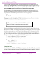
Here is an example of calling the function described above.
ldi
ldi
ldi
rcall
mpr, 138
XL, low($0112)
XH, high($0112)
Bin2ASCII
;
;
;
;
mpr <- 138
X <- $0112
X <- $0112
Call Bin2ASCII
There are many other functions within the LCD driver, but they are support functions for those described above and should not be
called individually. Modifying any function within the driver is not recommended as it could damage the performance of the function,
but feel free to play around if you like. With that said, if you do modify the driver or add another function that improves the
performance, let your TA know what you did and how it works or why it is better and we might add it to future versions of the driver.
Data Manipulation
© 2014 Oregon State University
ECE375 Manual
Page 26
Section Three: Data Manipulation and the LCD Display
To be able to move data from one memory to another, you first must understand the memory. The ATmega128 is an 8-bit AVR
architecture. Thus all register and data memory are 8-bit wide and all data is moved around 1-byte at a time. However, the AVR OpCode is 16 or 32-bits and for efficiency reasons the program memory is 16-bits or 2-bytes wide. This means that when you read
from the program memory, you will have to read 2-bytes for every address space in the program memory.
When writing a program, it is often necessary to include data directly into program memory instead of entering it into the data
memory each a time a simulation is run. The .DB (Data Byte) directive allows data to be written directly to the program memory
during compilation. For example, the following code demonstrates how to create data in program space:
DATA:
.DB $05, $F4
When the program is compiled, the hex data 0x05 and 0xF4 will be located in the program memory at the address specified by the
label DATA. To read this data, use the LPM (Load Program Memory) instruction.
Note: Since the program memory is 16-bits wide, the data after the .DB directive needs to be in
multiples of 16-bits. Otherwise, the compiler will insert an extra byte of data, usually $FF.
The movement within data memory is accomplished with the different variations of Load and Store commands. There are two main
addressing modes to move the data: direct addressing and indirect addressing. Direct addressing is best when you want to move data to
and from a single memory location, like an extended I/O register. Indirect addressing uses the X, Y, and Z-pointers and is useful for
moving data to multiple areas of data memory. For example, using indirect addressing in conjunction with a while-loop, you could
move ‘blocks’ of data around in memory. See the AVR Starters Guide for more information on pointers and indirect addressing. The
following is some pseudo-code you can use to properly read a bunch of data from program memory
Z <- Beginning Address of string in Program Memory
Y <- Beginning Address in Data Memory for string
do {
mpr <- ProgMem(Z), Z++
DataMem(Y) <- mpr, Y++
} while (Z != End Address of string in Prog Memory)
Writing Your Name
You are to write your name on the first line of the LCD Display and a simple phrase, such as “Hello World!” on the second line of the
LCD Display. In order to accomplish this, you must have you two strings in program memory using the .DB directive. Then read the
© 2014 Oregon State University
ECE375 Manual
Page 27
Section Three: Data Manipulation and the LCD Display
data from program memory and store it into the appropriate spots in data memory that are used for Line 1 and Line 2. Then make a
simple call to the correct function to display the two lines on the LCD display. You must first correctly initialize your program.
To help you along the process, skeleton code is provided. Use this as a starting point. When you are finished, demonstrate your LCD
Display to the TA to get credit. Have them sign below.
TA Signature: ______________________
STUDY QUESTIONS/ REP ORT
Write a short summary that details what you did and why, explain any problems you may have encountered, and answer the questions
below. Your write up should follow the required format given on the lab web page. Submit a hard copy of your write up and code to your TA
by the beginning of class the week following the lab. NO LATE WORK IS ACCEPTED.
Study Questions:
1. Take a look at the code you downloaded for today’s lab. Notice the lines that begin with .def and .equ followed by some
type of expression. These are known as pre-compiler directives. Define pre-compiler directive. What is the difference
between the .def and .equ directives? (HINT: see section 5.1 of the AVR Starter Guide given on the lab webpage.)
2. In this lab, you were asked to manipulate data by moving it around in memory. In fact, the AVR architecture has two different
memories, a program memory and data memory. Briefly explain the differences and purposes of these memories within your
write up.
3. You also learned how to make function calls. Explain how the function call works, its connection to the memory stack, and
why a RET instruction must be called to return from a function. To help you understand, comment out the stack pointer
initialization in the beginning of the code and try running the program. Observe and comment on this behavior.
CHALLE NGE
Not being content with displaying a static message, you would like to add some flare by creating a scrolling marquee style message. Your text
will scroll across the lines from left to right. When a character is at the end of a line, it will be displayed at the beginning of the opposite line,
i.e. a character on slot 16 of line 1 will go to slot 1 of line 2 and a character on slot 16 of line 2 will go to slot 1 of line 1. You will also want
to add a wait loop after all the characters have moved one slot so that you can read the characters. Below is an example of the display and
motion where ‘_’ signifies a space:
1:
Line 1 – “_____My_Name_is_”
Line 2 – “_______John_Doe_”
© 2014 Oregon State University
ECE375 Manual
Page 28
Section Three: Data Manipulation and the LCD Display
wait(.25sec)
2:
Line 1 – “______My_Name_is”
Line 2 – “________John_Doe”
wait(.25sec)
3:
Line 1 – “e______My_Name_i”
Line 2 – “s________John_Do”
wait(.25sec)
4:
Line 1 – “oe______My_Name_”
Line 2 – “is________John_D”
wait(.25sec)
etc...
Use the strings that are required for the lab to scroll. Submit this code with your report. Demonstrate the challenge problem to the TA for
credit.
© 2014 Oregon State University
ECE375 Manual
Page 29