1
^1
^2
USER MANUAL
PMAC-NC32
^3
^4
^5
Technical Documentation Manual
3Ax-ACC33N-xUxx
June 1999
PMAC-NC Technical Documentation Manual
Contents
1. Overview...................................................................................................................................1-1
Introduction ............................................................................................................................1-1
Manual Organization..............................................................................................................1-1
NC 32 Bit Software - WHAT and WHY ?.............................................................................1-2
Hardware/Software Requirements for NC–32 Bit.................................................................1-3
Hardware ...........................................................................................................................1-3
Software.............................................................................................................................1-3
2. Installation And Setup.............................................................................................................2-1
Installing The PMAC-NC32 for Windows Software ...............................................................2-1
Setting up PMAC Communications .......................................................................................2-3
Starting the Motion Applet .....................................................................................................2-4
Loading the NT Driver........................................................................................................2-4
NT Driver Startup...............................................................................................................2-5
Adding a PMAC Device .....................................................................................................2-5
Removing a PMAC Device ................................................................................................2-6
The Configuration Dialog .......................................................................................................2-6
Device Location .................................................................................................................2-6
PC Bus Device...................................................................................................................2-7
Establishing Communications............................................................................................2-7
Advanced Settings .............................................................................................................2-7
Setting Up PMAC-NC32 for Windows ...................................................................................2-9
General Settings Tab.......................................................................................................2-10
Title ..................................................................................................................................2-10
Machine Type ..................................................................................................................2-10
Backing Up The NC Configuration...................................................................................2-10
Restoring The NC Configuration......................................................................................2-10
Number Of Coordinate Systems......................................................................................2-11
Limits And Rates..............................................................................................................2-11
Language Setting.............................................................................................................2-12
Errors And Events............................................................................................................2-13
Probing.............................................................................................................................2-13
File Management .............................................................................................................2-14
Tools Settings Tab...........................................................................................................2-14
Coordinate System Settings Tab .........................................................................................2-16
Contents
i
PMAC-NC Technical Documentation Manual
Coordinate System Data File ...........................................................................................2-17
DNC Port & Flow Control Settings ...................................................................................2-17
DNC Parameter Settings .................................................................................................2-17
Code Settings Tab ...............................................................................................................2-18
UVW Incremental ............................................................................................................2-19
Compensation Correction ................................................................................................2-19
Tool Change During Motion.............................................................................................2-19
Automatic ‘H’ Codes ........................................................................................................2-19
Code Groups ...................................................................................................................2-20
Axis Settings Tab.................................................................................................................2-21
Motor / Axis Setting..........................................................................................................2-21
Axis Display Order ...........................................................................................................2-21
Axis – General .................................................................................................................2-22
Axis – Rates/Limits ..........................................................................................................2-23
Axis – Spindle ..................................................................................................................2-24
Axis – Jogging .................................................................................................................2-25
Axis – Home Reference...................................................................................................2-26
Performance Settings Tab...................................................................................................2-27
I/O Thread Priority............................................................................................................2-28
Buffer Thread Priority.......................................................................................................2-28
DNC Thread Priority.........................................................................................................2-28
Five Axis Settings Tab .........................................................................................................2-28
Glossary of Terms ...............................................................................................................2-30
Operating PMAC-NC for Windows ......................................................................................2-30
PMAC-NC32 for Windows Operator Screen Organization ..................................................2-32
PMAC-NC32 for Windows Operator Screens......................................................................2-38
PMAC-NC32 for Windows Standard Machine Control Functions........................................2-48
3. NC 32 Bit for Lathe Application..............................................................................................3-1
Introduction ............................................................................................................................3-1
Before Starting …. .............................................................................................................3-1
Lathe Block Diagram .........................................................................................................3-1
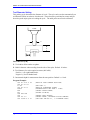
NC Basics ..............................................................................................................................3-2
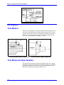
Tool Motion ........................................................................................................................3-2
Tool Movement Specification.............................................................................................3-2
Axis Move Specification.....................................................................................................3-3
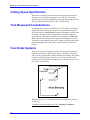
Cutting Speed Specification...............................................................................................3-4
Tool Movement Considerations .........................................................................................3-4
ii
Contents
PMAC-NC Technical Documentation Manual
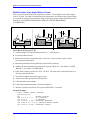
Coordinate Systems ..........................................................................................................3-4
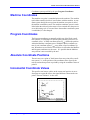
Machine Coordinates .........................................................................................................3-5
Program Coordinates.........................................................................................................3-5
Absolute Coordinate Positions...........................................................................................3-5
Incremental Coordinate Values .........................................................................................3-5
Reference point .................................................................................................................3-6
PMAC-NC for Windows Turning Center G & M Code Library ...............................................3-7
G&M Code Library .................................................................................................................3-9
CNC M-Codes ...................................................................................................................3-9
T-Codes ...........................................................................................................................3-12
Miscellaneous ..................................................................................................................3-12
G-Codes ..............................................................................................................................3-13
G00 Rapid Traverse Positioning......................................................................................3-13
G01 Linear Interpolation ..................................................................................................3-13
G01.1 Spline Interpolation ...............................................................................................3-14
G02 Circular Interpolation CW.........................................................................................3-16
G03 Circular Interpolation CCW ......................................................................................3-17
G04 Dwell ........................................................................................................................3-18
G07 Hypothetical Axis Interpolation.................................................................................3-19
G09 Exact Stop................................................................................................................3-19
G10.1 PMAC Data Input by Program ..............................................................................3-19
G17/G18/G19 (XY/ZX/YZ) Plane Selection .....................................................................3-19
G20/G21 Inch/Metric Input Select....................................................................................3-20
G25 Spindle Detect Off....................................................................................................3-20
G26 Spindle Detect On....................................................................................................3-21
G27 Reference Point Return Check ................................................................................3-21
G28 Return to Reference Point .......................................................................................3-22
G29 Return from Reference Point ...................................................................................3-22
G30 Return to Reference Point 2nd - 3rd ........................................................................3-22
G32 Thread Cutting .........................................................................................................3-22
G36 Tool Geometry Compensation .................................................................................3-23
G37 Tool Wear Compensation ........................................................................................3-23
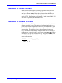
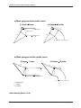
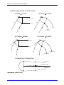
G40/G41/G42 Nose Radius Compensation ....................................................................3-23
Compensation Requirements ..........................................................................................3-25
How PMAC Introduces Compensation ............................................................................3-25
Speed of Compensated Moves .......................................................................................3-26
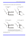
Treatment of Inside Corners............................................................................................3-26
Contents
iii
PMAC-NC Technical Documentation Manual
Treatment of Outside Corners .........................................................................................3-26
G50 Work Zero Set & Max Spindle Speed ......................................................................3-37
G52 Local Coordinate System Set ..................................................................................3-38
G53 Machine Coordinate Selection .................................................................................3-39
G54-59 Work Coordinate System 1-6 Selection..............................................................3-39
G61 Exact Stop Mode......................................................................................................3-40
G62/G63 Diameter X Axis/Radius X Axis........................................................................3-40
G64 Cutting Mode............................................................................................................3-41
G65 MACRO Instruction ..................................................................................................3-41
G70-76 Canned Cycles....................................................................................................3-41
G70 Canned Cycle...........................................................................................................3-42
G71 Multi-Turning Canned Cycle.....................................................................................3-42
G72 Multi-Facing Canned Cycle ......................................................................................3-43
G73 Pattern Repeat Canned Cycle ................................................................................3-44
G74 Canned Cycle...........................................................................................................3-44
G75 Groove Cutting Canned Cycle .................................................................................3-45
G76 Multi-Repetitive Threading Canned Cycle................................................................3-45
G90 Cycle 'A' Single Pass Cut.........................................................................................3-47
G90.1/G91.1 Absolute/Incremental Mode .......................................................................3-47
G92 Threading Cycle ......................................................................................................3-48
G93 Inverse Time Feed ..................................................................................................3-49
G94 Endface Turning Cycle.............................................................................................3-49
G98/G99 Feed Per Min/Feed Per Rev ............................................................................3-50
G96/G97 Constant Surface Speed (CSS) Mode .............................................................3-50
G98.1/G99.1 Canned Cycle Return Point........................................................................3-50
4. NC 32 Bit for Mill Application ................................................................................................4-1
Introduction ............................................................................................................................4-1
Before Starting … ..............................................................................................................4-1
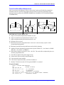
NC Mill Basics........................................................................................................................4-2
Tool Motion ........................................................................................................................4-2
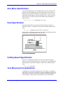
Tool Movement Specification.............................................................................................4-3
Axis Move Specification.....................................................................................................4-3
Feed Specification .............................................................................................................4-3
Cutting Speed Specification...............................................................................................4-4
Tool Movement Considerations .........................................................................................4-4
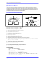
Coordinate Systems ..........................................................................................................4-5
Machine Coordinates .........................................................................................................4-5
iv
Contents
PMAC-NC Technical Documentation Manual
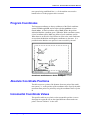
Program Coordinates.........................................................................................................4-6
Absolute Coordinate Positions...........................................................................................4-6
Incremental Coordinate Values .........................................................................................4-6
Reference Point .................................................................................................................4-6
G Code Library ......................................................................................................................4-8
CNC G-Codes....................................................................................................................4-8
G Codes...............................................................................................................................4-10
G00 Rapid Traverse Positioning......................................................................................4-10
G01 Linear Interpolation ..................................................................................................4-10
G01.1 Spline Interpolation ...............................................................................................4-11
G02 Circular Interpolation CW (Helical CW) ..................................................................4-11
G03 Circular Interpolation CCW (Helical Interpolation CCW) ........................................4-13
G04 Dwell ........................................................................................................................4-15
G09 Exact Stop................................................................................................................4-15
G10 Programmable Data Input........................................................................................4-15
G10.1 PMAC Data Input By Program ..............................................................................4-16
G17/G18/G19 (XY/ZX/YZ) Plane Selection .....................................................................4-16
G25 Spindle Detect Off....................................................................................................4-17
G26 Spindle Detect On....................................................................................................4-17
G27 Reference Point Return Check ................................................................................4-17
G28 Return to Reference Point .......................................................................................4-18
G29 Return from Reference Point ...................................................................................4-18
rd
G30 Return to Reference Point 2nd - 3 .........................................................................4-18
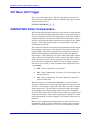
G31 Move Until Trigger....................................................................................................4-19
G40/G41/G42 Cutter Compensation ...............................................................................4-19
Compensation Requirements ..........................................................................................4-21
How PMAC Introduces Compensation ............................................................................4-21
Speed of Compensated Moves .......................................................................................4-21
Treatment of Inside Corners............................................................................................4-22
Treatment of Outside Corners .........................................................................................4-22
G43/G44/G49 Tool Length Compensation + /- and Cancel............................................4-33
G45/G46/G47/G48 Single Block Tool Offsets .................................................................4-33
G50/G51 Coordinate Scaling...........................................................................................4-34
G50.1/G51.1 Coordinate Mirroring ..................................................................................4-34
G52 Local Coordinate System Set ..................................................................................4-35
G53 Machine Coordinate Selection .................................................................................4-36
G54-59 Work Coordinate System 1-6 Selection..............................................................4-36
Contents
v
PMAC-NC Technical Documentation Manual
G61 Exact Stop Mode......................................................................................................4-37
G64 Cutting Mode............................................................................................................4-37
G65 MACRO Instruction ..................................................................................................4-38
G68/G69 Coordinate System Rotation ............................................................................4-38
G70 Bolt Hole Circle Pattern............................................................................................4-38
G70.1 Bolt Hole, Center Hole Ignore Pattern .................................................................. 4-39
G71 Arc Pattern ...............................................................................................................4-40
G72 Bolt Line Pattern ..................................................................................................... 4-41
G80-89 Canned Cycles....................................................................................................4-42
G80 Canned Cycle Cancel ..............................................................................................4-43
G81 Drilling Cycle ............................................................................................................4-43
G82 Boring, Spotfacing, Counter Sinking Cycle (Free cutting)........................................4-45
G83 Deep Hole (Peck) Drilling Cycle...............................................................................4-47
G84 Tapping Cycle ..........................................................................................................4-48
G85 Reaming, Boring Cycle ............................................................................................4-50
G87 Boring Cycle (Manual or programmed quill return) ..................................................4-52
G88 Boring Cycle (Free cutting, manual or programmed quill return)............................4-53
G89 Boring Cycle (Finishing cut, free cutting) .................................................................4-54
G90/G91 Absolute/Incremental Mode .............................................................................4-56
G90.1/G91.1 Arc Radius Abs/Inc Mode...........................................................................4-56
G92 Work Coordinate System Set .................................................................................4-56
G93 Inverse Time Feed ..................................................................................................4-57
G94/G95 Feed Per Min/Feed Per Rev ...........................................................................4-58
G98/G99 Canned Cycle Return Point..............................................................................4-58
M Code Library ....................................................................................................................4-59
CNC M-Codes .....................................................................................................................4-59
M00 Program Stop...........................................................................................................4-60
M01 Optional Stop ...........................................................................................................4-60
M02 Program Rewind ......................................................................................................4-60
M03 Spindle Clockwise....................................................................................................4-60
M04 Spindle Counterclockwise........................................................................................4-61
M05 Spindle Stop.............................................................................................................4-61
M06 Tool Change ............................................................................................................4-61
M08 Coolant On...............................................................................................................4-61
M09 Coolant Off...............................................................................................................4-62
M19 Spindle Orient ..........................................................................................................4-62
M30 End of Program (and Rewind) .................................................................................4-62
M87 Start Data Gathering................................................................................................4-62
vi
Contents
PMAC-NC Technical Documentation Manual
M88 End Data Gathering .................................................................................................4-63
M98() Subroutine Call & M99 Return from Subroutine Call.............................................4-63
M98(c:\cnc\machines\mill\newpawn.nc) L16 ...................................................................4-63
T-Codes ...............................................................................................................................4-64
T-Code format .................................................................................................................4-64
Miscellaneous ......................................................................................................................4-64
Block Delete character: /..................................................................................................4-64
APPENDIX I PARAMETRIC PROGRAMMING. .......................................................................................1
APPENDIX II. APPLICATION NOTES
APPENDIX III. TOUCH PROBING FOR PMAC NC
Contents
vii
PMAC-NC Technical Documentation Manual
viii
Contents
PMAC-NC Technical Documentation Manual
1
Overview
Introduction
This manual discusses installing and configuring the PMAC-NC 32 BIT
for Windows software program for the particular application controller
configuration. An overview of the software installation process and a list
of installed files is provided here. Readme files on the media provided
contain the latest revision instructions.
Manual Organization
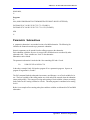
Chapter 1. Overview. Organization of the manual and an introduction
to the PMAC – NC 32 Bit for Windows. Brief description of the 32 Bit
software and information on why 32 bit over 16 bit. Basic information
on the requirements for installing 32-Bit Software for Windows, including Hardware and Software requirements. How and where to get the required files for 32 Bit Software.
Chapter 2. Installation and Setup. Describes the installation and
setup procedures for NC - 32 Bit software, including how to set up the
NC-32 bit software for the required application. Different changes required in the registry, .CFG and .BAT files. Use of PEWIN32 and
MOTION.EXE for setup.
Chapter 3. NC 32 Bit for Lathe Application. Describes the basics of
NC 32 Bit as configured for Lathe, and provides instructions for the
PMAC-NC 32 for Windows application.
Chapter 4. NC 32 Bit for Mill Application. Describes the basics of
NC 32 Bit for Mill, and provides instructions for the PMAC-NC for
Windows application.
Overview
1-1
PMAC-NC Technical Documentation Manual
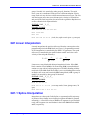
NC 32 Bit Software - WHAT and WHY ?
The PMAC-NC32 for Windows program is a true 32 bit, multi-threading,
registry configurable, Microsoft Windows based software program developed specifically for CNC machine tool operators. The PMAC-NC32
for Windows runs on a standard Pentium based PC, in either Microsoft
Windows ’95, Windows ’98, or Windows NT 4.0 operating systems.
The PMAC-NC32 for Windows GUI program is designed to be displayed
to any SVGA (Super Video Graphics Array) monitor at 800 x 600 resolution.
PMAC-NC32 for Windows also includes NC Verify Lite. NC Verify
Lite is a true 32 bit, Windows based, solid modeling tool verification
software program by Sirius Systems (San Jose, CA). NC Verify Lite
provides up to a three axis mill, or a two axis lathe, G code “back plotting” software program.
PMAC-NC32 for Windows controls the axis motion of a machine tool –
a standard lathe or a standard mill, depending upon how it is configured.
The configuration is easy to do with a setup program called “motion.exe.” The user can add or modify the G, M and T codes, and the
PLC program very easily.
This 32 bit software was developed because —
•
DOS / WINDOWS 3.1, 16 Bit system will be phased out.
•
WINDOWS 95/98 32 Bit is more powerful and cost effective.
•
32 bit is more stable and secured.
•
It is faster and provides better graphic support.
•
The settings are handled by registry files.
•
•
1-2
There is no need for additional or external software to Run NC
32.
Most of the user interface is through .DAT files, making message changes easy to do.
•
Provides online Special Diagnostic page setting to check I/O .
•
Easy to change ERROR messages .
Overview
PMAC-NC Technical Documentation Manual
Hardware/Software Requirements for NC–32 Bit.
Hardware
The minimum hardware required to run NC 32 bit is shown below.
•
•
•
•
•
Pentium 133 or better.
32 MB RAM or better
SVGA 15” Monitor with 1 MB Video RAM.
Mouse or pointing Device
The basic hardware which is used by NC 32
PAMC (1, 1.5, 2 or LITE )
Dual Port RAM card.
The user can further improve performance by using better PC hardware
available in the market.
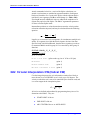
Software
The minimum software required to run NC 32 bit for windows is listed
below.
•
•
•
•
•
•
Overview
Operating System – WINDOWS 95 / 98 , WINDOWS NT
PEWIN 32 - PMAC Executive for WINDOWS 32 bit. Delta
Tau’s PEWIN (PMAC Executive for Windows 32 Bit ) program,
(version 2.2x or later) is loaded on the computer, and communications with the PMAC board AND Dual Port Ram are established. If this condition is not satisfied, refer to Delta Tau’s
PEWIN manual for help.
PMACPLOT.EXE: Delta Tau’s PMACPLOT application
used for plotting different parameters from PMAC.
MOTION.EXE: Delta Tau’s MOTION.EXE is used to set up
the NC 32 application. This software uses the Windows registry
database which is the standard way of setting the environment
for Windows 95/98 or NT.
NC Verify: PMAC-NC32 for Windows also includes NC Verify
Lite. NC Verify Lite is a true 32 bit, Windows based, solid
modling tool verification software program by Sirius Systems
(San Jose, CA). NC Verify Lite is a G code “back plotting”
software program for up to a three axis mill, or a two axis lathe.
.PLC and .PMC files: Delta Tau’s standard PLC and motion
codes for LATHE or MILL operation.
1-3
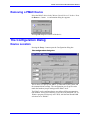
PMAC-NC Technical Documentation Manual
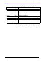
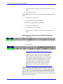
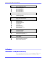
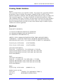
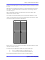
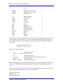
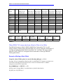
Files Downloaded To The PMAC Board for Advantage 600/700
Program Name
PMAC Name
ADV600m.plc
PLC 1
Control Panel PLC . Detects real world and PMAC I/O changes
Override.plc
PLC 2
Controls different override states
Handle.plc
PLC 4
Controls manual pulse generator input
Spindle.plc
PLC 5
Controls how the spindle is interfaced to PMAC-NC32 for Windows
Lube.plc
PLC 7
Handling of Lubrication I/O
Mill.g
Mill.m
Mill.t
Comments
Prog 1000 Controls how G-codes are interpreted
Prog 1001
Prog 1002
Controls how M-codes are interpreted
Controls how T-codes are interpreted
Address.h
Establishes PMAC-NC32 for Windows M-variable definitions
OEM.h
Establishes user specific system variable definitions
The Delta Tau PMAC-NC32 for Windows software program is designed
to run in either a Microsoft Windows 95 or 98, or Windows NT operating environment. The software is distributed on five 3.5“ floppy disks.
1-4
Overview
PMAC-NC Technical Documentation Manual
Installation And
Setup
Installing The PMAC-NC32 for Windows Software
Delta Tau’s PMAC-NC32 for Windows software program is designed to
run in Microsoft Windows 95, Windows 98, or Windows NT4.0 operating system. The software is distributed with an automated installation
utility that will assist computer memory configuration, load the necessary operational files onto the computer’s hard drive, and configure the
machine hardware you will be using. It will also create the required default registry structure.
Before starting installation, make sure the requirements are fulfilled, as
explained in Section 1 under “Hardware/Software Requirements for
PMAC-NC32 for Windows.”
WARNING
To ensure an expedient and safe installation, the Systems Integrator or OEM responsible for the installation
and integration of a PMAC-NC32 for Windows application must possess at least a basic understanding of electronics, machine tool technology, and the PMAC motion
control board. If you have any questions about a particular aspect of the installation or integration, do not
attempt the task until you are sure you have a thorough
understanding of what you are about to attempt.
Start Windows on the computer. Place disk 1 of the PMAC-NC32 for
Windows program in the floppy drive. Follow the instructions listed
below for the appropriate operating environment.
Windows 95/98: from START, select RUN. A dialog box appears. Type
the letter of the drive in which the floppy disk has been loaded, followed
by a colon and the word “setup” (i.e., a:setup). Press the Enter key,
or click on the OK button. Follow the setup instructions.
Installation and Setup
2-1
PMAC-NC Technical Documentation Manual
Automatic Installation: The automatic installation program creates a
Setup box, which loads the Install Shield (the automatic installation
program). Follow the setup instructions.
When Install Shield starts up, a Welcome box advises you to end any
Windows programs that may be running at the time. Once you have
ended all other Windows programs, click on the Next button.
A Software License Agreement box appears. If you agree with the licensing agreement, click on the YES button.
A User Information dialog box appears. Enter your name and company information in the appropriate boxes. Once the information is correct, click on the Next button.
A Choose Destination Location box appears. You can select the suggested file loading structure by clicking on the Next button. Click on the
Browse button if you want to load the PMAC-NC32 for Windows program in any other sub-directory. The default location will be
C:\Program Files\Delta Tau\NC 2.0.
A Setup Type box appears. This dialog box allows you to select the type
of setup you prefer – TYPICAL, COMPACT or CUSTOM. Select the
preferred type of setup and click the Next button. Suggested type of installation is TYPICAL.
A Select Program Folder box appears. This dialog box allows you to
direct where the application icons will be displayed. Click on the Next
button. The suggested program folder is PMAC-NC32 for Windows.
A Check Setup information box appears. This will summarize the information about your installation selection. If you are satisfied with the
selection, click the Next button to begin copying files.
A Start Copying Files box appears. Disk 1 of the PMAC-NC32 for
Windows program now begins loading. Once disk 1 is installed, a Setup
Needs The Next Disk box appears. Insert disk 2, then press the Enter
key or click on the OK button. Repeat this procedure until all disks of
the PMAC-NC32 for Windows program are loaded.
Upon completion of copying files a Select Components box appears.
There are three different components. If you select Do not update registry files, then the existing registry files will not be updated. This selection is recommended only when you are upgrading to a newer version of
PMAC-NC32 for Windows. The other two components are for LATHE
(Turning) applications or MILL (Machining Center) applications. The
program is set up for one or the other, but not both. Once the selection is
completed, the registry files and the other components are modified.
Upon completion a Setup Complete box appears. This informs you that
all the required files are copied. Restart Windows before starting the
application.
All the files required for setting up the PMAC-NC32 for Windows program are available in C:\Program Files\Delta Tau\NC 2.0\Lathe or Mill
2-2
Installation and Setup
PMAC-NC Technical Documentation Manual
subdirectories. The PMAC-NC32 for Windows program will create the
below-listed subdirectories.
C:\Program Files \Delta Tau \nc 2.0
(Default Location for copying files
in installation)
Examples
(All PLC examples)
Lathe
(Standard files, .PLC and G, M, &T code files for Lathe)
Mill
(Standard files, .PLC and G, M &T code files for Mill)
NCVerify
(Third party software for verifying the motion)
C:\Program Files \Common Files
Address.h
Oem.h
Io600.h
Adv600 h
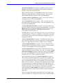
Setting up PMAC Communications
The Motion.Exe applet is used to establish communications with the
Delta Tau PMAC motion control cards when using 32-bit applications
such as PEWIN32 and PMAC-NC32 for Windows. No applications, including PEWIN32, will be used to add, remove or configure PMACs in
your system. Rather, communication settings have been centralized in
your operating system, making the set up of each PMAC much like other
devices in your computer (i.e. video card, sound card etc.). The configuration information for PMAC is now stored in the Windows registry,
where in the past it has been stored in initialization (*.ini) files. The
Motion.Exe Applet manages this registry information.
Note
Before running this application, it is important that all
applications that use PComm32 (the Delta Tau 32-bit
communication driver) be shut down. This includes
PEWIN32, PMAC-NC32 for Windows, and any applications developed with PComm32 or PTalk.
Installation and Setup
2-3
PMAC-NC Technical Documentation Manual
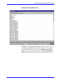
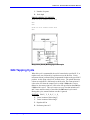
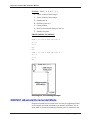
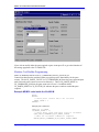
Starting the Motion Applet
All setup is done through the "MOTION CONTROLS" applet (or the
"Motion.Exe" application), which is accessible through your operating
system’s CONTROL PANEL.
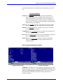
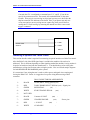
Once you have the Windows Control Panel open, click on the icon
shown below.
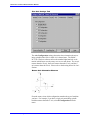
The following dialog box appears:
Note:
The Unload, Load, and Startup buttons appear only if
you are running Windows NT. The NC Setup button is
visible only if the driver has PMAC-NC capability.
Typically the Load and Unload are never used except in
rare trouble shooting cases. The "Startup" button may
be used to tell the operating system how to load the
PMAC communications driver (PComm32).
Loading the NT Driver
The Load Driver, Unload Driver and Startup… buttons are visible only
if you are in the Windows NT operating system. They are not visible in
Windows 95/98 because the low-level driver for Windows 95
(PMAC.VXD) is self-loading on demand.
If the Windows NT driver (PMAC.SYS) is currently loaded into system
memory, the Unload Driver button is enabled and highlighted. The
Load Driver button is enabled and highlighted if the driver is not in
memory.
2-4
Installation and Setup
PMAC-NC Technical Documentation Manual
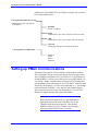
NT Driver Startup
Windows NT provides the capability to select when the low-level driver
is loaded into memory. This is provided to allow communication with
the PMAC device when no user is logged on.
Pressing the Startup.. button brings up the Driver Startup dialog box.
Select the desired start method and press OK. You will have to reboot
for the Boot and System methods. Unloading or loading the driver will
initiate the other methods.
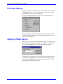
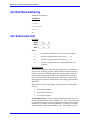
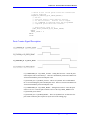
Adding a PMAC Device
If this is your first time running the Motion.Exe applet, no PMAC device
will be listed in the "Motion Control Devices" list box. To add a PMAC
device, press the Add button. The following dialog box appears:
This dialog box is prompting you for a device number to associate with
the PMAC you are adding. Always start with your first PMAC as Device 0, the second PMAC in your system as Device 1, and so on. The
applet handles the enumeration for you.
Installation and Setup
2-5
PMAC-NC Technical Documentation Manual
Removing a PMAC Device
Select the PMAC device in the "Motion Control Devices" list box. Press
the Remove… button. A confirmation dialog box appears.
Pressing OK completes removal of the device.
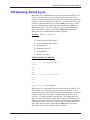
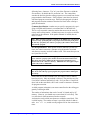
The Configuration Dialog
Device Location
Pressing the Setup… button opens the Configuration dialog box.
The configuration dialog box
This is where you specify how PMAC is connected to your system, and
the communications settings. The configuration you set up here must
match the hardware jumper settings on the PMAC itself.
The PMAC can be configured to use any of three different communication methods: serial port, VME BUS, or PC BUS; but the PMAC-NC for
Windows program will run only in PC BUS, with the Dual Ported RAM
selections set to “D4000.”
2-6
Installation and Setup
PMAC-NC Technical Documentation Manual
PC Bus Device
Select In PC Bus as the device location. This allows three other entries:
•
Port Address: The port address of the PMAC is required, and
must match the bus address jumper settings on the PMAC, or the
bus address dip switch settings on PMAC2. The most common
cause of communications problems is incorrect hardware address settings.
•
Interrupt Adr: The interrupt address setting is optional. If you
do not require interrupts, set this value to NONE. If used, the
value must match the jumper settings that have been set on the
PMAC. PMAC-NC32 for Windows does not use interrupts for
operations.
•
DPRAM Adr: Set to D4000. See your Dual Ported RAM
manual for details. PMAC-NC32 for Windows requires Dual
Ported RAM, and it must be set to “D4000” for proper program
operation.
Establishing Communications
Once you have made the appropriate settings in the Configuration Dialog
Box, pressing OK initiates setup of the Windows registry database,
which is required for communication with the PMAC card. When communications has been established, the following message appears:
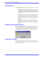
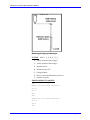
Advanced Settings
The Advanced button on the PMAC Configuration dialog box is used to
configure Dual Ported RAM settings typically used with the PMACNC32 for Windows software.
Installation and Setup
2-7
PMAC-NC Technical Documentation Manual
PMAC Advanced Communications Setup Page
The Binary Rotary Buffer in PMAC's DPRAM allow the host computer
to send program commands to PMAC in binary format for the fastest
possible transmission of these commands. In order to utilize this feature,
rotary buffers must be defined in both DPRAM and within PMAC’s internal memory. Please reference your PMAC User’s Manual for information about defining binary rotary buffers within PMAC.
The combined binary rotary buffers in PMAC and DPRAM allow for
downloading program lines from the host during execution of a program,
and for overwriting already executed program lines. This permits continuous execution of programs larger than PMAC's memory space and
real-time downloading of program lines (such as G-code programs and
MDI programs in PMAC-NC32 for Windows).
Each coordinate system can have a binary rotary buffer in DPRAM. The
buffer should be sized (value in hex bytes) to allow enough room for the
distance ahead of the execution point you wish to load. Since most applications utilizing rotary buffers will not strain PMAC's memory requirements, it is a good idea to oversize the buffer by a good margin.
2-8
Installation and Setup
PMAC-NC Technical Documentation Manual
Note
The default setting is sufficient for almost all PMACNC32 for Windows programs. Consult Delta Tau before
changing the default DPRAM Rotary 1 size.
Note:
If you are using PMAC-NC32 for Windows, only two
coordinate systems are supported; therefore only two
DPRAM rotary buffers can be defined. Most PMACNC32 for Windows applications will require only one
binary rotary buffer. The only exception is “Dual Turret
Lathes.”
The DPRAM Var Start Address defines the address that corresponds to
the beginning of the open memory DPRAM buffer. It also corresponds
to the end of the last DPRAM binary rotary buffer; consequently, the location of this address determines the relative size of each buffer between
$D240 and DPRAM Var Start Address. This address information is
stored in the Windows registry database. The memory from 0xDDE0
through 0xDFFF is reserved for internal use by PMAC-NC32 for Windows. The space from “DPRAM Var Start Address” through 0xDFFF is
untouched by the Win32 driver. In most cases the default settings will
be adequate and will not require modification. Please see the PMAC
Option 2 Dual Ported Ram User’s Guide for more information regarding
DPRAM topics.
Setting Up PMAC-NC32 for Windows
The Motion.Exe applet is used to configure the registry values required
by PMAC-NC32 for Windows. If the PMAC-NC version of the PMAC
driver library is available on the system, there will be an additional NC
Setup… button visible in the dialog box. This is not available in the
“communications only” version. Clicking on NC Setup… takes you to
the main NC setup dialog.
In order for PMAC-NC32 for Windows to operate properly, communications utilizing Dual Ported RAM must be established in the PMAC Device(x) Configuration dialog box prior to starting PMAC-NC32 for
Windows software.
Installation and Setup
2-9
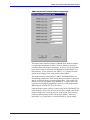
PMAC-NC Technical Documentation Manual
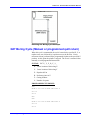
General Settings Tab
The PMAC-NC General Settings Tab
Title
The text string entered here will be displayed in the title bar of the
PMAC-NC32 for Windows application, and can be up to 63 characters
long.
Machine Type
Select one of two possible machine type settings, Mill or Lathe. These
settings primarily affect the parsing of G code, and how some commands
are interpreted. Example: T2M6 for a milling machine as opposed to
T0202 for a lathe.
Backing Up The NC Configuration
Most NC values are stored in the Windows registry database. The exceptions are tool values, coordinate system values, and event logging
text.
The Save as Reg File… button on the PMAC-NC general configuration
tab allows you to select a file for storing the current NC configuration.
Restoring The NC Configuration
The Load Reg File… button on the PMAC-NC general configuration tab
allows you to restore a PMAC-NC configuration from a selected file.
2-10
Installation and Setup
PMAC-NC Technical Documentation Manual
Number Of Coordinate Systems
Each PMAC-NC32 for Windows system can have up to two coordinate
systems. Two coordinate systems provide two program buffers for a single machine type. (Example: a dual-turret lathe.)
The buffers share the same G code interpreter, and use “semaphores” to
protect against tool collisions between the separate coordinate systems.
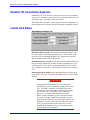
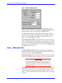
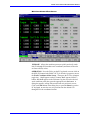
Limits And Rates
Limits/Rates Settings Tab
Maximum rapid override sets the maximum allowable PMAC timebase percentage value during rapid mode moves. The variable rapid
override value is set through the PMAC-NC graphical user interface.
The maximum allowed value is 200 percent.
Maximum feedrate override sets the maximum allowable PMAC timebase percentage value during all other feedrate-controlled moves. The
variable rapid override value is set through the PMAC-NC32 for Windows graphical user interface. The maximum allowed value is 200 percent.
Default gauge block height sets the default thickness of an operators
gauge block. This value is algebraically added to the Z-axis tool offset
settings.
WARNING
Setting the Maximum handle incr. to a value greater
than 0.0100 can create a hazardous runaway-like condition. The PMAC controller will attempt to move the
selected axis the corresponding number of pulses multiplied by this value. For instance, if you set this parameter to 1.0 and turned the handwheel one turn,
PMAC would command a jog move of 1000 user units
(assuming a 100 ppr manual pulse generator), and continue motion long after the user had stopped input to the
handwheel! Set this value so that when the speed multiplier is set to the maximum value and a move is commanded by the handwheel, the axis stops motion when
you stop input to the handwheel.
Installation and Setup
2-11
PMAC-NC Technical Documentation Manual
Maximum handle incr. sets the maximum axis travel distance, in user
units, per pulse of the handwheel input, when the jog speed multiplier
input is set to the maximum value.
Least handle incr. sets the minimum axis travel distance, in user units,
per pulse of the handwheel input, when the jog speed multiplier input is
set to the lowest value.
Least jogging incr. sets the axis travel distance, in user units, when an
incremental jog command is issued and the speed multiplier input is set
to the lowest value. The actual axis travel distance is determined by this
value multiplied by the speed multiplier input, the lowest being x1.
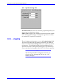
Language Setting
You can set up custom message and error warnings to be displayed by
the PMAC-NC user interface. This is done by establishing a text file
with these messages, and identifying its location in the Message/Errors
text file box located in the Languages Settings Tab shown below.
Please refer to your PMAC-NC32 for Windows manual for information
on how to create the message file.
Languages Setting Tab
Error Language lets you choose which language DLL PMAC-NC32 for
Windows will load for displaying standard error messages.
System Language lets you choose which language DLL PMAC-NC32
for Windows will load and utilize within the graphical user interface.
Note
English is the only language presently available for 32bit applications. Other languages are being developed,
and will be available from Delta Tau Data Systems, Inc.
in the future.
2-12
Installation and Setup
PMAC-NC Technical Documentation Manual
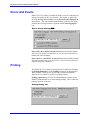
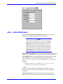
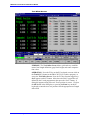
Errors And Events
PMAC-NC32 for Windows includes the ability to log all event and error
messages issued by the NC user interface. This feature is enabled by
checking the Log error events box in the Errors/Events Settings Tab
shown below. The user definable path and name of the text file which
contains these messages must be specified in the Events logging file
box.
Errors / Events Settings Tab
Issue a kill (^K) to PMAC on fatal error determines whether PMAC
will issue a kill (Ctrl-K) on fatal error, or rely on a user-written PLC to
handle fatal error conditions.
Issue a abort (^A) to PMAC on stop error determines whether PMAC
will issue an abort (Ctrl-A) on stop errors, or rely on a user-written PLC
to handle stop error conditions.
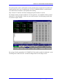
Probing
The PMAC-NC32 for Windows probing feature is enabled by checking
the Probing Enabled box in the Probing settings tab as shown below.
When enabled, various power up time and reset time initialization
functions are set, which are specific to probing routines.
Probing report file specifies the file and path that are used to record
DPRNT statements that are executed during probing. This is where the
probing report file is located.
Probing Setting Tab
Installation and Setup
2-13
PMAC-NC Technical Documentation Manual
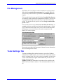
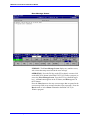
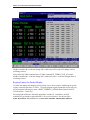
File Management
The PMAC-NC32 for Windows software includes file security features.
When the Use controlled file management box is enabled, M98 calls
will look only in the directories specified in the File Management dialog box.
Files located in the directory specified by the Controlled files directory
are read-only when controlled file management is enabled. The files can
be purged automatically from this directory at a user-determined time
period. The duration for this period is set in the Purge controlled files
period window.
Files located in the directory Local (non-controlled) files directory are
standard read/write, and can be accessed in the normal manner. A high
level of document control and security can be achieved when Windows
NT directory access control features are used in conjunction with
PMAC-NC security features.
File Management Tab
Please refer to the PMAC-NC Integrator’s Manual for more information
about File Management features.
Tools Settings Tab
Tool data, including offsets and tool location, is stored in a Windows
initialization text database file. You can select the location and name for
this file as shown below. The 32-bit version is compatible with the 16-bit
version. If the Motion.Exe applet cannot find the file you enter, it will
prompt you to create one.
Number of Tools sets the number of tools that will be available to the
PMAC-NC32 for Windows software. The maximum number of tools is
99.
2-14
Installation and Setup
PMAC-NC Technical Documentation Manual
The Tools Setting Tab
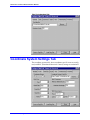
Coordinate System Settings Tab
The coordinate system tab is where coordinate specific items are configured, and DNC (Distributed Numerical Control) settings are maintained.
.
Installation and Setup
2-15
PMAC-NC Technical Documentation Manual
Select the coordinate system you are addressing. If you have set one coordinate system in the General Settings tab then you will be able to select only coordinate system one.
Coordinate System Data File
Enter the file path here where coordinate system data settings are to be
stored. If the Motion.Exe applet is unable to find the file it will ask if
you would like it created.
You can also use the browse button to search for the desired file.
DNC Port & Flow Control Settings
The DNC port settings allow transfer of NC programs from another
computer via the host PC’s serial port. Please see the PMAC-NC Integrator’s Manual for further information on how to use the DNC feature.
The DNC Port and DNC Flow Control settings must match the serial
port configuration of the device from which the transfer is to occur.
DNC Parameter Settings
DNC Parameters allows you to set up a minimum buffer size for serial
DNC transfer of NC programs. When issued a request for a DNC transfer, PMAC-NC32 for Windows creates a buffer on the host PC’s hard
disk space equal to the Minimum Buffered Lines x Maximum Line
Length. The DNC buffer will increase in size according to demand, but
will not become smaller than the initial size determined by the buffered
lines and the line length mentioned earlier.
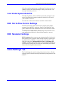
Code Settings Tab
The Code Settings tab contains setting values relative to how a G-code
program is parsed, and the actions performed during interpretation of the
program.
2-16
Installation and Setup
PMAC-NC Technical Documentation Manual
Code Settings Tab
UVW Incremental
On some machine tools (especially lathes) it is desired that the U,V & W
axes represent an incremental command of X, Y & Z respectively.
Note
If you actually have U, V or W axis motors do not check
this box. Commands will never reach these motors but
will be converted to X, Y or Z commands.
Compensation Correction
On PMAC devices that do not have an extended block look-ahead feature (i.e. all except for PMAC Turbo), blocks which do not command
motion during G41 or G42 mode moves can cause PMAC-NC to temporarily remove cutter compensation. To avoid this situation, enable
Compensation Correction.
Tool Change During Motion
Some machines can operate the tool changer without stopping axis motion. If you wish to have axis motion during tool changes, enable the
Tool change during motion box.
Automatic ‘H’ Codes
Some machines do not have a separate code group for tool length compensation, but require that an H code provide the tool number and also
turn tool length compensation off and on. Normally commanding an H0
will turn off the height offset, but if you set this value to true, an H code
Installation and Setup
2-17
PMAC-NC Technical Documentation Manual
that is not zero will turn the tool height offset on as though you commanded a G43.
Code Groups
The Code Settings tab determines how PMAC-NC32 for Windows will
parse G-codes in the start-up code. This tab allows you to define which
G-code number will be associated with each specific G-code group.
Each Code Group will accept a default profile entry.
PMAC-NC supports user-defined G-codes G60.1 through G69.1 and
G70.1 through G79.1. The “Gxx.1” format is used in order to avoid conflicts with existing RS-274 default G-codes entries. These codes pass
and accept all RS-274 address parameters. The Code Group 20 – User
Codes accept profile entries of the form user1=1060 through
user10=1069 for user defined G-codes G60.1 through G69.1, and profile
entries of the form user11=1070 through user20=1079 for user-defined
G-codes G70.1 through G79.1.
To define a “G64.1,” configure the applicable code parameters as shown
below.
Please see the PMAC-NC Integrator’s Manual for information on their
use and configuration.
Example for User G64.1 Settings
2-18
Installation and Setup
PMAC-NC Technical Documentation Manual
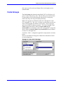
Axis Settings Tab
The Axis settings tab is where you will configure information for your
machine tools, motors and axes.
The Axis Settings Tab
Motor / Axis Setting
If this is the first time you are running PMAC-NC setup, all axes will be
undefined, and require a motor assignment. A “?” will be displayed in
the box immediately above the motor selection box, indicating that the
currently selected axis is not assigned to a motor.
To define a motor/axis relationship:
1. Select the coordinate system the axis is to be in.
2. Select the desired axis name.
3. Select the motor number for the axis. If you select a motor currently in use by another axis, a warning appears.
4. Make sure the Enabled check box on the General tab is
checked.
5. If you want this axis to be displayed on the operator’s screens
then check the Displayed check box.
Axis Display Order
Various screens in PMAC-NC32 for Windows display multiple axis
names. The order of axis display from top to bottom is determined by
the order from left to right in the Display Order string.
Installation and Setup
2-19
PMAC-NC Technical Documentation Manual
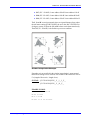
Axis – General
The Axis - General Settings tab includes parameters that are used to
enable an axis, format properties of the axis in the user display, and determine the user units of the axis.
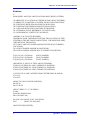
If an axis is to be utilized by the PMAC-NC32 for Windows program, the
Enabled box must be checked. Once the axis is enabled, you can decide
whether to include the axis in the user display by checking the Display
box.
If the axis will be operating in metric units, check the Metric Units box.
Feedback pulses/unit configuration tells PMAC-NC32 for Windows
how many encoder counts correspond to one user unit. (i.e., encoder
counts per inch, or encoder counts per millimeter) This value depends
on the mechanical configuration of the machine (i.e., leadscrew pitch),
number of encoder pulses per one motor-shaft revolution, PMAC’s
“I900” decode multiplier for the axis, and if the axis is going to be encoder counts per inch or encoder counts per millimeter.
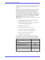
Example for Motor 1 (set for inches):
Encoder on Motor = 2500 Lines/Rev
Ball Screw = 10mm/Rev
PMAC Encoder Decode Variable I900 = 3 (CW 4x Decode)
4cts 2500lines
rev 25.4mm
×
×
×
= 25400 cts
in
line
10mm
rev
in
Note
If user units are in millimeters, remove the 25.4 mm/in
portion of the equation.
2-20
Installation and Setup
PMAC-NC Technical Documentation Manual
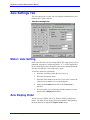
Axis – General Settings Tab
You must specify how position information will be displayed in the
PMAC-NC32 for Windows user interface. The Display Formats section
contains entries for inch, metric and degree display formats.
Two digits separated by a decimal point represent the display format.
The first digit is the width of the display in number of digits. Always set
this to 9. The second digit is the number of digits after the decimal
point. (E.g. 9.4 would display 15.5500.)
The Unit precision to PMAC setting controls the precision with which
PMAC will handle all numeric calculations. In general this value should
be set to two decimal places higher than will be displayed in the user interface. (E.g. If the “Display formats” is set to 9.4, then Unit precision
to PMAC should be set to 9.6.)
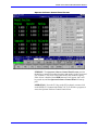
Axis – Rates/Limits
The Rates/Limits Settings tab includes parameters for setting motor
maximum speed, error limits, and inposition bandwidth. You determine
the units in the Axis – General Settings Tab.
Maximum rapid rate determines the maximum speed for an axis during
rapid mode programmed moves. PMAC’s Ix16 is set by this parameter.
Warning
Setting the Warning Following or Fatal Following Error
to zero will disable these features, allowing dangerous
conditions to exist. Never set these values to zero for an
operational machine.
Warning follow error limit sets the warning following error limit for a
particular axis. When this number is reached, PMAC-NC32 for Windows
issues a warning message to the operator through the graphical user interface. A value of zero disables this feature. PMAC’s Ix12 is set by this
parameter.
Installation and Setup
2-21
PMAC-NC Technical Documentation Manual
Fatal follow error limit sets the fatal following error limit for a particular axis. When this number is reached, the amplifier enable signal is
disabled and a warning message is issued. PMAC’s Ix11 is set by this
parameter.
Inposition band sets the maximum distance from commanded position
before an axis will be considered “in-position,” when not performing a
move. PMAC’s Ix28 is set by this parameter.
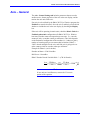
Axis – Rates/Limits Settings Tab
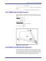
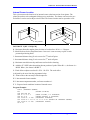
Axis – Spindle
The Spindle tab contains entries for setting up the machine spindle. If
the particular axis will be used as a spindle, check the Is Spindle box.
Note
Only axes which will be used as an actual spindle should
have the Is Spindle box checked, i.e., a lathe that uses
“C” axis also as a spindle should be checked.
The “Max RPM limit” sets the maximum spindle speed in revolutions
per minute. This value is overwritten by G92 and G50 commands.
2-22
Installation and Setup
PMAC-NC Technical Documentation Manual
Axis – Spindle Settings Tab
Max RPM default determines the maximum programmed spindle speed
at power up, in revolutions per minute .
Primary ratio configures the mechanical gear ratio between the spindle
motor and the spindle cartridge. If multiple-ratio gear boxes are used, a
user-written PLC program will be required.
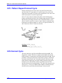
Axis – Jogging
The axis jogging speed parameters are set in the Jogging Settings Tab.
The units are in either inches per minute or millimeters per minute, as
defined in the Axis General Settings Tab, and are used during continuous jog moves. The individual settings are selected either by the jog
speed selector switch on the operator control panel, or the software operator control interface through the PMAC-NC32 for Windows program.
Note:
The Advantage 500 allows configuration of all five jog
selector rates; the Advantage 600/700 use only “Low,
Medium, and High.”
Installation and Setup
2-23
PMAC-NC Technical Documentation Manual
Axis – Jogging Settings Tab
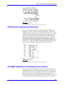
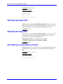
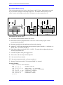
Axis – Home Reference
The Axis – Home Reference Settings Tab determines how a homing
request will be controlled by PMAC-NC32 for Windows.
Note
The “Home Ref” configuration is used to establish how
PMAC-NC32 for Windows will home an axis. On line
command is used for a machine which has a home
switch associated with the axis; PLC is used when the
machine does not have a home switch associated with
the axis, and must use an overtravel switch for homing;
Motion program is used for homing gantry machine
tools that have an axis “slaved” to a “master” axis.
On line command (#nHM) issues a standard on-line HM homing command
to PMAC for the particular axis. Used when the axis has a home switch.
PLC (DPRAM bit) sets a bit in DPRAM which can then initiate a homing
routine through a user written PLC by using a logical IF statement.
PMAC-NC32 for Windows uses the CS_HOME_INIT bit for this purpose.
Example:
IF(@ON(CS_STATUS4_M,CS_HOME_INIT));Homing routine
@SET_OFF(CS_STATUS4_M,CS_HOME_INIT)
ENDIF
This PLC statement looks for the homing initialization bit, runs the
homing routine, and resets the initialization bit once the homing routine
is complete.
Motion program runs a user-written motion program homing routine.
PMAC-NC32 for Windows does this by issuing a “bnr” command to ini-
2-24
Installation and Setup
PMAC-NC Technical Documentation Manual
tiate the homing sequence. (“b” issues a “begin” statement to PMAC;
“n” is the program number; and “r” issues a “run” command to PMAC.)
A motion program is used for gantry with master, slave axes.
Home using motion program number determines which motion program number PMAC-NC32 for Windows will command when using the
Motion program method of homing. Default is 3 for either PLC or
PMC.
Axis – Home Reference Settings Tab
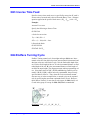
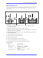
Performance Settings Tab
The PMAC-NC32 for Windows program is multi-threaded. Each thread
performs specific tasks independently from other threads except where
data is shared.
Because certain data is shared between these threads, a thread having the
highest priority can cause others to wait. The performance tab allows
you to balance shared time between these threads in order to maximize
system throughput. You can set the ”DNC Thread Priority” to “Idle” if
you won’t be using DNC. This will free up processor time for other activities.
Installation and Setup
2-25
PMAC-NC Technical Documentation Manual
Performance Settings Tab
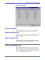
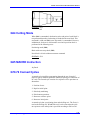
I/O Thread Priority
The I/O thread maintains data from PMAC’s I/O and intercepts PLCsponsored input. The default priority for this thread is “Normal.”
Buffer Thread Priority
The buffer thread parses the input stream, supplies the PMAC with motion data, and monitors PMAC error reporting. The default priority for
this thread is “Normal.”
DNC Thread Priority
The DNC thread monitors external I/O through the PC serial port. This
thread priority normally is set to IDLE, unless you plan on using DNC
serial feed to the PMAC-NC32 for Windows program.
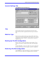
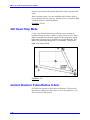
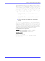
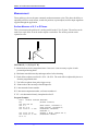
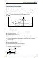
Five Axis Settings Tab
The FiveAxis Settings Tab should be used in conjunction with the
PMAC-NC Integrator’s Manual for proper configuration. Configuration
of this tab is required only for users with machines that have one- or
two-axis articulating spindle heads. If you are not using this type of configuration, select Disable Offsets from the menu.
2-26
Installation and Setup
PMAC-NC Technical Documentation Manual
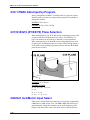
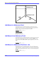
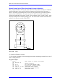
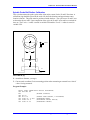
Five Axis Settings Tab
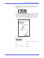
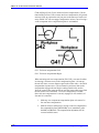
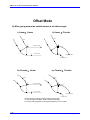
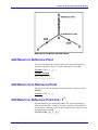
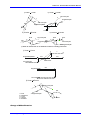
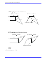
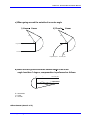
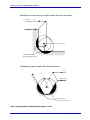
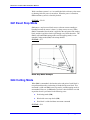
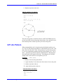
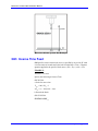
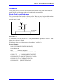
The Axis Configuration settings determine what orientation the articulating spindle head will be in while in it’s homed state. The PMACNC32 for Windows software utilizes the standard right hand rule to determine which linear axes the rotary axes are to rotate about. The A-axis
rotates about the X-axis, the B-axis rotates about the Y-axis, and the Caxis rotates about the Z-axis. Please refer to the drawing below for clarification.
Rotary Axis Orientation Diagram
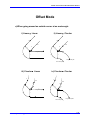
From the menu, select which configuration matches the type of machine
you have. For example, if you have a single-axis articulating spindle
head that rotates about the Y axis, select B Configuration from the
menu.
Installation and Setup
2-27
PMAC-NC Technical Documentation Manual
Glossary of Terms
DNC
Distributed Numerical Control. The transfer of NC programs from one host
computer to another via serial communications.
DPRNT
A command used by PMAC-NC Probing to generate probing reports.
Event Logging File
An ASCII text file in which are recorded all messages which are displayed in the
NC environment, including warnings and error messages.
GUI
Graphical User Interface. The PMAC-NC32 for Windows is a GUI for machine
tool operators.
Semaphores
Blocks of code that notify the PMAC-NC32 for Windows program as to the particular location of the physical axes of the machine in order to avoid collisions.
Thread
A portion of code that can get a time slice from the operating system to run concurrently with other portions of code, and must be associated with a process
(PMAC-NC32 for Windows is the “process.”) However, a Win32-based application can initiate multiple threads for a given process to enhance the application
for the user by improving throughput, enhancing responsiveness, and aiding
background processing.
Windows Registry
The central information database for 32-bit Windows operating systems is called the
Registry. The registry maintains information about hardware components and devices
that have been identified through an enumeration process in the hierarchical structure of
the registry. When new devices are installed, the system checks the existing configuration
in the Registry to determine the hardware resources (for example, IRQs, I/O addresses,
DMA channels, and so on) that are not being used, so the new device can be properly
configured without conflicting with a device already installed in the system.
Operating PMAC-NC for Windows
The following describes the operational methodology and “operator
screens” available from Delta Tau’s “PMAC-NC32 for Windows” CNC
graphical user interface (GUI) software program. The PMAC-NC32 for
Windows program allows CNC operators to —
2-28
•
quickly and easily load and execute RS-274 type
G code programs
•
define work coordinate systems (G54 ~ G59)
•
establish tool length offsets
•
and monitor program execution and machine position from easyto-access and uncomplicated operator screens
Installation and Setup
PMAC-NC Technical Documentation Manual
The PMAC-NC32 for Windows GUI program is designed to be displayed
on any SVGA (Super Video Graphics Array) monitor, at 800 x 600
resolution.
The PMAC-NC32 for Windows program emulates the operational methodology of today’s most popular CNC controller systems, and uses
screen background colors judicially to aid the machine operator to immediately identify which screen is currently active. The operator
screens in the PMAC-NC32 for Windows program are organized to present relevant machine operational information to the machine operator in
a consistent and uncluttered manner. See PMAC-NC32 for Windows
Operator Screens for pictures of the various screens.
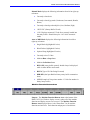
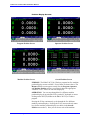
The PMAC-NC32 for Windows program provides the following operator
screens standard:
•
Five Machine Position Display Screens (Machine, Operator,
Commanded, Distance To Go, Overall)
•
Two G Code Program Execution Screens (G Code Program
Check & G Code Program Text Screens)
•
Background Text Editor Screen
•
Work Coordinate Offset Screen (G54 ~ G59)
•
Tool Length & Cutter Compensation Setting Screen
•
Settings Screen With Parts Counter & Parts Total
•
Diagnostics Screen With I/O Monitor Status
•
Message Screen For Error Messages
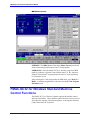
Only the “middle area” of the PMAC-NC32 for Windows operator
screen changes, and these screens can be identified easily by the screen
background colors. The specific background colors are listed below:
Operator Screen Display
Installation and Setup
Background Color
Machine Position Display Screens (Five
Possible)
Black
G Code Execution Screen (Two Possible)
Blue
Background Text Editor Screen
White
Settings Screen With Parts Counter
Gray
Error Message Screen
White
Diagnostics Screen With I/O Monitor
Status
Black
2-29
PMAC-NC Technical Documentation Manual
PMAC-NC32 for Windows Operator Screen Organization
Information presented by the PMAC-NC32 for Windows operator
screens is divided into six sections, and is organized in the following
manner (beginning from the top of the PMAC-NC32 for Windows operator display screen):
1. "Title Bar" With Windows Minimize, Maximize, & Program Close
Button
2. "G Code Program File Name Bar" With “O” Program Number & “N”
Block Number Display
3. "Modal Information Display Area" Is Dependent On Which Operator
Screen Is Active. This is the only display area that changes during
operation of the PMAC-NC32 for Windows program.
4. "Feedrate & Spindle Information Display Area"
5. "Current Machine Operational Information Display Area"
6. "Machine Function Buttons Area"
Listed below are the specific details regarding the features and purposes
for each of the six sections that constitute the PMAC-NC32 for Windows
software program.
2-30
Installation and Setup
PMAC-NC Technical Documentation Manual
Title Bar
Purpose: The Title Bar can be used to minimize, maximize, or close
the PMAC-NC32 for Windows software program. The title bar is also
used to provide a customizable and unique name for the particular
PMAC-NC32 for Windows software program that is running at the time.
The Title Bar has the following components, starting from left to right:
•
Windows Close Screen Button. Works only when PMAC-NC32
for Windows is in Manual mode.
•
Program Title Name. Can be any text string up to 128 characters long. Customizable through the Motion.Exe setup program
or Windows registry.
•
Windows Minimize screen button
•
Windows Maximize screen button
•
Windows Close Screen button. Works only when PMAC-NC32
for Windows is in Manual Mode.
G Code Program File Name Bar
Purpose: The G Code Program File Name Bar displays the file name
of the last executed file, or the file currently loaded into the G code execution buffer..
The G Code Program File Name Bar has the following components,
starting from left to right:
Installation and Setup
•
Name of the last executed, or currently loaded, G Code program
•
Number of times a sub-routine has been repeated
•
The O program number (supporting Fanuc style G Code program names)
•
The N block number (if programmed into the G Code program)
2-31
PMAC-NC Technical Documentation Manual
Modal Information Display Area
Purpose: The Modal Information Display Area displays a specific
operator screen (the Overall Position screen is shown above) as determined by which mode or function is currently being accessed by the
PMAC-NC32 for Windows program. This is the only display area that
changes while operating the PMAC-NC32 for Windows program.
The Modal Information Display Area has the following characteristics:
•
Screen area changes depending on which mode or function is
currently being accessed by the PMAC-NC32 for Windows program.
•
Background colors help identify the operator screen currently
being displayed.
Feedrate & Spindle Information Display Area
Purpose: Provides the operator with constantly updated information regarding the current machine feedrate & spindle speeds.
The Feedrate & Spindle Information Display Area displays the following information from left to right:
2-32
•
Last or currently programmed machine feedrate
•
Actual machine feedrate
•
Feed per minute or inches per revolution
•
Cutting, Threading, Or Rapid Mode
Installation and Setup
PMAC-NC Technical Documentation Manual
•
Current position of feedrate override switch on operator control
panel
•
Current rapid override
The Spindle information displays the following information from left to
right:
•
Spindle Off, CW, Or CCW
•
Current programmed spindle speed
•
Maximum programmable spindle speed
•
Current actual spindle speed
•
Constant surface speed: On/Off
•
Current position of spindle override switch on operator control
panel
Current Machine Operational Information Display Area
Manual Mode
OR
Auto & MDI Mode
Note
PMAC-NC32 for Windows has three (3) operational
modes, “Manual,” “MDI,” & “Auto.” Auto & MDI
modes display the same information in the “Current Machine Operational Information Display Area,” so only
manual & auto modes are displayed above. The three
operational modes of the PMAC-NC32 for Windows
program can be accessed via the “Operator Control
Switch Panel,” or the “Operator Software Control
Panel.”
Purpose: Displays current machine status information depending on
which operational mode the PMAC-NC32 for Windows program is currently selected. The Current Machine Operational Information Display Area also displays the currently active error status. The current
machine error status can always be found in the lower left while in either
manual, MDI, or auto mode.
Installation and Setup
2-33
PMAC-NC Technical Documentation Manual
Manual Mode displays the following information from left to right, top
to bottom:
•
Currently selected axis
•
Currently selected jog mode (Continuous, Incremental, Handle,
Home)
•
Currently selected speed multiplier (Low, Medium, High)
•
“BUF CLS” (Rotary Buffer Closed)
•
“0/0” (Displays amount of G Code lines currently loaded into
the rotary buffer. Should always be “0/0” while in manual
mode)
Auto or MDI Mode displays the following information from left to
right, top to bottom:
•
Single Block (highlighted if active)
•
Block Delete (highlighted if active)
•
Optional Stop (highlighted if active)
•
Currently active G Codes
•
Machine Run or Stop Status
•
Machine In Position Status
•
BUF OPN (rotary buffer opened) should always be displayed
while in either MDI or Auto mode
•
RS274 (Type of G Code Being Executed)
•
DPR-BIN (dual port RAM to binary rotary buffer communications)
•
13/51 (Example of line pointer number / G Code line number in
binary rotary buffer)
Machine Function Buttons Area
Purpose: The Machine Function Buttons Area at the bottom of the
PMAC-NC32 for Windows display screen is where all of the machine
functions and display screens are accessed. The Machine Function
Buttons Area displayed above is the “Home Row” for all machine
functions and activities. Each function and purpose is listed below:
2-34
Installation and Setup
PMAC-NC Technical Documentation Manual
F1
Sub-Menu Toggle Button
F2
POSITION Display Button (Machine, Operator, Commanded, Distance-To-Go, & Overall Position Displays are accessed from this
button)
F3
PROGRAM Display Button (G Code Check & G Code Text Screens
are accessed from this button)
F4
OFFSET Display Button (Used to set G54 ~ G59 work coordinates)
F5
TOOLS Display Button (Used to set tool length offsets & cutter
compensations)
F6
SETTING Display Button (Used to access machine On Time, G
Code Program Execution Timer, Parts Counter, & Parts Total)
F7
DIAGNOSTICS Display Button (When accessed, displays current
status of machine real world I/O, Axis Homing Status, Spindle
Status, & Tool Changer Status)
F8
REWIND Display Button (When machine is in “Manual” mode,
pressing this button forces the currently active G Code program to
Rewind to the beginning of the program)
F9
EDITOR Display Button (Starts the buffer editor)
F10
MESSAGE Display Button (Displays all error messages with
time/date stamp)
F11
OPERATOR Display Button (Allows operator to use this screen &
PC keyboard to control all machine functions & operations. Access
to this screen can be turned off if desired by settings in the Windows
registry)
Or
DRY RUN Display Button (When operator screen is turned off by
settings in the Windows registry, this changes the rapid feedrate
override to the Programmed Feedrate Override. Otherwise this
function is found on the Operators page)
F12
Installation and Setup
Functions Toggle Button
2-35
PMAC-NC Technical Documentation Manual
PMAC-NC32 for Windows Operator Screens
When the PMAC-NC32 for Windows program first begins, the following
screen appears. This is the Program Check/Software Control Panel
Screen as displayed below:
Program Check/Software Control Panel Screen
PURPOSE: Provides instant access to the program check screen and
software control panel. The software control panel can be turned off in
the Windows registry.
2-36
Installation and Setup
PMAC-NC Technical Documentation Manual
Position Display Screens
Program Position Screen
Operator Position Screen
Machine Position Screen
Overall Position Screen
PURPOSE: The PMAC-NC32 for Windows program has five machine
position display screens available. Four of these are shown above. The
Distance To Go screen appears exactly like the Program, Operator,
and Machine Position screens, except that it shows the appropriate
“Distance To Go” values for each axis displayed).
OPERATION: You can step through the five different machine
position displays by pressing the F2 key on the PC keyboard, or mouse
clicking on the POS (F2) button in the PMAC-NC32 for Windows
program.
Pressing the F2 key continuously cycles through the five different
machine position displays. Pressing the F1 key accesses the sub menu
keys for the machine position displays (as shown in the Overall
Position screen above). Now you can access each of the machine
Installation and Setup
2-37
PMAC-NC Technical Documentation Manual
position displays directly, without having to continuously press the F2
key.
Position Definitions
Program: The Program position is equal to the current machine
position minus the Work Coordinate offset, minus any G92
offsets and minus active tool offsets. If no work offsets are
active the Program Position will be based upon a default work
offset of G54. The Program Position display is meaningful only
when operating a part program.
Operator: The Operator Position is equal to the the current machine
position minus the Operator-defined Work Coordinate offset.
Machine: The Machine Position is equal to the current axis distance
away from the home position.
Commanded: The Commanded Position is equal to the end position of
the current move in Program coordinates.
Dist To Go: The Dist To Go Position is equal to the difference between
the Commanded Position and the Program Position.
Follow Error: The Follow Error Position is equal to the difference
between the instantaneous desired position and the actual
machine position.
G Code Program Execution Screens
Program Check Screen
G Code Text Screen
PURPOSE: The PMAC-NC32 for Windows program has two G Code
Program Execution Screens: the G Code Program Check Screen (left )
and the G Code Program Text Screen (right). These screens provide
all the necessary information about the G code program they are
currently executing.
2-38
Installation and Setup
PMAC-NC Technical Documentation Manual
OPERATION: Press the F3 key on the PC keyboard, or mouse click on
the PRG (F3) button in the PMAC-NC32 for Windows program to toggle
between the two different G code program execution screens.
During Automatic operation, a G code file is loaded into the G Code
Program Execution screen. The PMAC-NC32 for Windows program
helps identify which line of G code is being executed, by displaying the
G code program lines in the following manner:
G Code Line Color
Status Of G Code Line
G Code Lines In Yellow
G Code Lines That Have Already Been
Executed
G Code Line In Solid Red Bar
The Currently Executing Line Of G Code
G Code Line In Red
Rectangular Box
The Next Line Of G Code To Be
Executed
G Code Lines In White
G Code Lines To Be Executed
The G Code Program Check Screen displays 12 lines of G code at a
time, and also displays the following G code program information:
Program Position Display
Distance to Go Display
Active M (Miscellaneous)
Codes
Active G Codes
Active T (Tool Number)
Codes
Currently Programmed F (Feedrate) Word
Active H & D offsets (tool length height & tool length diameter offsets)
The G Code Program Text Screen displays 25 lines of G code at a
time. Though this screen does not display machine program information
like the G Code Program Check Screen, this screen is particularly
useful when an operator wants to examine more of the G code program.
Installation and Setup
2-39
PMAC-NC Technical Documentation Manual
Background Text Editor Screen
PURPOSE: The Background Text Editor Screen provides an easy-touse, standard ASCII text, G code file editor. Megabyte size files can be
loaded into the PMAC-NC32 for Windows Background Text Editor
Screen. Once a G code file has been loaded into the Background Text
Editor Screen, program modifications can be made quickly and easily.
2-40
Installation and Setup
PMAC-NC Technical Documentation Manual
Note
Once a G code file has been loaded into the G Code
Program Execution Screen, that same G code file cannot
be loaded into the Background Text Editor Screen. An
error message will be generated stating that the PMACNC32 for Windows program will not allow this
sequence of operation. PMAC-NC32 for Windows
program forces this constraint so there is no possiblity of
modifying or confusing the currently loaded file in the G
code program execution screen.
OPERATION: Press the F3 key on the PC keyboard, or mouse click on
the PRG (F3) button in the PMAC-NC32 for Windows program, to
access the Background Text Editor Screen. Once the Background
Text Editor Screen is displayed, press the F12 key on the PC keyboard,
or mouse click on the F12 button in the PMAC-NC32 for Windows program, to access a full complement of text editor features. These text
editor features include:
Installation and Setup
♦ Save File (save file
with modifications
♦ Save As File (save modified file with
new name)
♦ Search (text &
block search)
♦ Replace (replace old text with new
text)
♦ Cut (cut text from
program)
♦ Copy (copy onto file the contents in
clipboard)
♦ Paste (paste text
from clipboard)
♦ Undo (undo last file modification)
2-41
PMAC-NC Technical Documentation Manual
Work Coordinate Offset Screen
PURPOSE: Allows the machine operator to quickly and easily establish G54 through G59 machine work coordinate (sometimes referred to
as fixture offsets) values.
OPERATION: Press the F4 key on the PC keyboard, or mouse click on
the OFS (F4) button in the PMAC-NC32 for Windows program to access
the Work Coordinate Offset Screen. Then press the F12 key (function
toggle key). Set X appears on the F2 button, Set Y appears on the F3
button, and Set Z appears on the F4 button. Jog the axes to the desired
work coordinate point, then press the appropriate axis Set button. A
dialog box appears, asking if the new desired axis position is correct.
Click on the OK button in the dialog box, or press the Enter key on the
PC keyboard, to enter the new axis positions into the desired G54
through G59 work coordinate location.
2-42
Installation and Setup
PMAC-NC Technical Documentation Manual
Tool Offset Screen
PURPOSE: The Tool Offset Screen allows quick and easy establishment of tool length definitions, gage block height, and cutter compensation values.
OPERATION: Press the F5 key on the PC keyboard, or mouse click on
the TOOLS (F5) button in the PMAC-NC32 for Windows program, to
access the Tool Offset Screen. Press the F12 key (function toggle key).
Set Z appears on the F2 button. Move the tool to the Z set position (as
defined by the G code programmer), then press the “Set Z” button. A
dialog box appears asking if the new Z axis position is correct. Click on
the OK button in the dialog box, or pressing the Enter key on the PC
keyboard, to enter the new axis positions into the appropriate tool length
offset field.
Installation and Setup
2-43
PMAC-NC Technical Documentation Manual
Settings Screen with Parts Counter & Parts Total
PURPOSE: The Setting Screen with Parts Counter & Parts Total
screen provides machine operating and power-on totals, cycle time and
cutting time, and parts counter, parts required total. This screen also
provides the current time and date.
OPERATION: Press the F6 key on the PC keyboard, or mouse click on
the SETTING (F6) button in the PMAC-NC32 for Windows program to
access this screen. Press the F12 key (function toggle key). A Parts
dialog box appears on the F2 button. Press this button to enter the
amount of parts required for a particular machining operation.
2-44
Installation and Setup
PMAC-NC Technical Documentation Manual
Error Message Screen
PURPOSE: The Error Message Screen displays any machine errors,
with a time/date stamp associated to the error message.
OPERATION: Press the F10 key on the PC keyboard, or mouse click
on the MSG (F10) button in the PMAC-NC32 for Windows program, to
access the Error Message Screen. Press the F12 key (function toggle
key). A Clear button appears on the F2 button, and Reset appears on
the F3 button.
Press the Clear button to clear any error messages that are posted in the
error message field (error messages that have been corrected). Press the
Reset button to issue a Reset command to the PMAC-NC32 for
Windows program.
Installation and Setup
2-45
PMAC-NC Technical Documentation Manual
Operator Software Control Panel Screen
PURPOSE: The Operator Software Control Panel Screen provides
the ability to control all machine functions and modes via this screen and
a PC keyboard. The screen can be turned off in the Windows registry.
If this screen is disabled, the OPER button will still appear, but it will
be grayed out, and the Operator Software Control Panel will not appear.
OPERATION: Press the F11 key on the PC keyboard, or mouse click
on the OPER (F11) button in the PMAC-NC32 for Windows program, to
access the Operator Software Control Panel Screen.
2-46
Installation and Setup
PMAC-NC Technical Documentation Manual
MDI Editor Screen
PURPOSE: The MDI (Manual Data Input) Editor Screen provides the
ability to manually program and execute G code programs.
OPERATION: Place the PMAC-NC32 for Windows program in MDI
mode (by either the “Operator Control Switch Panel” or the “Operator
Software Control Panel”) to program and execute a G code program up
to 32 kilobytes in size.
After entering the G code program into the MDI editor, press Write To
Buffer to send the programmed G code lines into the G Code Program
Execution screen.
PMAC-NC32 for Windows Standard Machine
Control Functions
The PMAC-NC32 for Windows program supports the machine control
functions listed below. These machine control functions can be accessed
from either the Operator Control Switch Panel, or the Operator Software
Control Panel and a PC keyboard.
Installation and Setup
2-47
PMAC-NC Technical Documentation Manual
Cycle Start
Feed Hold
Axis Select (X, Y, Z, A, B, C, U, W)
Single Block
Block Delete
Optional Stop
Feedrate Override (0 to
150%)
Spindle Override (50
to 110%)
Speed Multiply (X1, X10, 100)
Coolant On / Off / Auto
100 PPR Manual
Pulse Generator
Spindle Direction (Off, CW, CCW)
Mode Select (Auto, MDI, Manual Continuous, Incremental / Handle, Home)
PMAC-NC32 for Windows program standard G Codes support the following:
•
•
•
•
Rapid (G00), linear (G01), with 2D & 3D circular and helical
(G02, G03) interpolation
High-Speed contouring mode (G10.1 & G11.1)
Plane specification for circular interpolation and cutter radius
compensation (G17, G18, & G19)
•
Inch/Millimeter selection (G20 & G21)
•
Automatic and multi-repetitive threading (G32 & G76)
•
Cutter radius compensation (G40, G41 & G42)
•
Cutter length offset (G43, G44, & G49)
•
Mirroring, scaling and rotation (G50, G51, G68 & G69)
•
Multiple work coordinate system selection (G54 ~ G59)
•
•
Programmable canned cycles; boring, tapping (floating and
rigid), drilling (G70 ~ G73, & G80 ~ G89)
Multi-Finishing cycle, multi-turning cycle, multi-facing cycles
for lathes (G70, G71, G72)
•
Absolute and incremental modes (G90 & G91)
•
Coordinate system set (G92)
•
•
2-48
Floating point range and resolution on all position, distance, and
speed displays
Inverse time feed, feed per minute, and feed per revolution (G93,
G94 & G95)
Constant surface speed and constant RPM spindle (G96 & G97)
Installation and Setup
PMAC-NC Technical Documentation Manual
3
NC 32 Bit for Lathe
Application
Introduction
This chapter defines the basics of NC Lathe and instructions for the
PMAC-NC 32 for Windows Application. The goal of this document is to
provide descriptions of the software within the required hardware environment. The hardware requirement is explained in the requirement
chapter.
The default G-codes delivered with PMAC-NC-32 are designed to emulate a Fanuc 10 style of G-codes. Hence a CNC program posted for a
Fanuc 10 should work without any changes.
This document also contains the section: the "NC Programmers Reference"; a detailed description of RS-274 style G-Code programming.
Before Starting ….
Before running the Lathe application please confirm the checklist.
1. Read the Basics of NC Lathe.
2. Installed the application for Lathe.
3. Run MOTION.EXE for setting up PMAC for DUAL port RAM
communication and AXIS configuration.
4. Check the default or reference PLC file and G/ M / T code files
downloaded to PMAC using PWIN32.
Lathe Block Diagram
The basic block diagram explains the requirement for the Lathe applic ation.
Make sure of DUAL PORT RAM OPTION with a DESIRED PMAC
option .
NC 32 Bit for Lathe Application
3-1
PMAC-NC Technical Documentation Manual
NC Basics
Tool Motion
The tool moves through lines and arcs within the table boundaries as required for manufacturing a part. Rather than moving the tool in a working machine, the table is moved. The actual table displacement will be
the reverse of commanded tool motion. This manual assumes that the
tool moves with respect to the workpiece, or table.
Tool movement along circular arc
Tool movement along straight line
Tool Movement Specification.
The function of moving the tool along straight lines and arcs is called
interpolation. Program commands for interpolated motion are called the
preparatory functions and specify the type of interpolation used. The
three basic interpolation preparatory functions are:
3-2
NC 32 Bit for Lathe Application
PMAC-NC Technical Documentation Manual
Tool movement along straight line:
G01
Tool movement along circular rc:
G02 / G03
Tool movement along specified trajectory:
G01.1
Reference of the axis position word will execute motion. The control will
coordinate the movement of the axis motors to execute the command. In
this document the generalized form of the axis position word,
X__Y__Z__, will be used.
Axis Move Specification
Last commanded position is the start and the final position is in the command. This final position may be either an absolute position (a point referenced to program zero) or a relative move (signed increment of extension from present point). This is specified with axis move or position
words, the axis address letter followed by a numeric literal:
X5.2Y0Z-.001 length units (in / mm)
FEEDRATE PER TIME UNITS
FEEDRATE PER REVOLUTION UNITS
Movement of the tool at a specified speed for cutting a workpiece is
called the feedrate. Feedrates can be specified similarly with the feed
word:
F150.0 length/time units (in/min mm/min) or Feed Per Rev (in/rev
mm/rev).
Length units are within program control (see the G-code definitions in the
next section). Time units are set by the machine builder.
I parameter I190 controls the time units.
NC 32 Bit for Lathe Application
3-3
PMAC-NC Technical Documentation Manual
Cutting Speed Specification
The relative rotational speed of the tool with respect to the workpiece
during a cut is called the cutting speed. As for the CNC, the cutting
speed can be specified by the spindle speed in rpm units using the S address specification followed by the value: S250 rpm units.
Tool Movement Considerations
At multiple move (or block) boundaries, the CNC applies a coordinated
ramp of the vector velocity into and out of the point without stopping.
The result of this is move blending. Because of blending, corners are not
cut sharply. If sharp corners are required to be cut, Exact Stop (or a
dwell) must be commanded in the block or set modally (see G04, G09,
G61). This will force an in-position stop before starting the next move.
"In-position" means that the feed motor is within a specified range about
the commanded position. (This range is determined by machine tool
builder.)
Coordinate Systems
There are two types of coordinate systems. One fixed by the machine
mechanics at the time of build. And a relative coordinate system specified by the NC program that coincides with the part drawing. The control
is aware of only the first one. Therefore, in order to correctly cut the
workpiece as specified on the drawing, the two coordinate systems must
be set at the same position.
When a workpiece is set on the table, these two coordinate systems lay
as follows:
Coordinate system specified by the CNC: Machine Coordinates.
3-4
NC 32 Bit for Lathe Application
PMAC-NC Technical Documentation Manual
Coordinate system specified by the part: Program Coordinates.
Machine Coordinates
The machine zero point is a standard point on the machine. The machine
tool builder normally decides it in accordance with the machine. A coordinate system having the zero point at the machine zero point is called
the machine coordinate system. The machine coordinate system is established when the reference point return is first executed after the power is
on or the homing cycle is executed. Once the machine coordinate system
is established, it is not changed.
Program Coordinates
The Program coordinates are normally within one of the Work coordinate systems, G54, through G59 and are either absolute positions or incremental values. A Work coordinate offset, Woff, defines the position
within the Machine coordinate space. Within the Work coordinate system a Local coordinate offset, Loff, may define a Local coordinate system. When there are no Work or Local offsets in effect then the Machine
and Program coordinates are the same. It is possible that the Machine
zero position is not accessible by the tool.
Absolute Coordinate Positions
The tool moves to a point at "the distance from zero point of the coordinate system," i.e. to the position of the coordinate values. Specify the
tool movement from point A to point B by using the coordinate values of
point B.
Incremental Coordinate Values
This specifies tool moves relative to the current tool position. A move
from point A to point B will use the signed difference between the two
points. The term "Relative" is also used.
NC 32 Bit for Lathe Application
3-5
PMAC-NC Technical Documentation Manual
Reference point
Aside from Machine zero a machine tool may need to locate other fixed
positions corresponding to attached hardware, i.e.: a tool changer. This
position is called the reference point (which may coincide with Machine
zero). The tool can be moved to the reference point in two ways:
Manual reference point return is performed by manual operation.
Automatic reference point return is performed in accordance with programmed commands.
In general, manual reference point return is performed first after the
power is turned on. This will usually be the same, as the homing function since the reference point will be at a fixed offset from the Machine
zero position. In order to move the tool to the reference point for tool
change thereafter, the function of automatic reference point return is
used.
3-6
NC 32 Bit for Lathe Application
PMAC-NC Technical Documentation Manual
PMAC-NC for Windows Turning Center G & M
Code Library
Valid As Of 6/1/96, Version 1.60 Software
Bold indicates start-up G Code.
G-Code
Function
G00
G01
G01.1
G02
G03
Rapid Traverse
Linear Interpolation
Spline Interpolation
Circular Interpolation, CW
Circular Interpolation, CCW
G04
G09
G10
G10.1
Dwell
Exact Stop Check
Program Data Input
PMAC Data Input
G17
G18
G19
XY Plane Selection
ZX Plane Selection
YZ Plane Selection
G20
G21
Inch Mode
Metric Mode
G25
G26
Spindle Speed Detect Off
Spindle Speed Detect On
G27
G28
G29
G30
Reference Point Return Check
Return To Reference Point
Return From Reference Point
2nd Reference Point Return
G32
Thread Cutting
G40
G41
G42
Tool Nose Radius Compensation Cancel
Tool Nose Radius Compensation Left
Tool Nose Radius Compensation Right
G50
G50.1
G52
G53
Coordinate System Setting & Maximum Spindle Speed
Coordinate System Setting Cancel
Local Coordinate System Setting
Machine Coordinate System Setting
G54
G55
G56
G57
G58
G59
Work Coordinate System 1
Work Coordinate System 2
Work Coordinate System 3
Work Coordinate System 4
Work Coordinate System 5
Work Coordinate System 6
NC 32 Bit for Lathe Application
3-7
PMAC-NC Technical Documentation Manual
G61
Exact Stop Mode
G62
G63
Diameter Mode
Radius Mode
G64
Cutting Mode
G70
G71
G72
G73
G74
G75
G76
Multi-Finishing Cycle
Multi-Turning Cycle
Multi-Facing Cycle
Pattern Repeat Cycle
End Face Peck Drilling
Groove Cutting
Multi-Repetitive Threading
G90
Outer Diameter/Internal Diameter Cutting Cycle
G90.1
G91.1
Absolute Programming
Incremental Programming
G92
Thread Cutting Cycle
G93
Inverse Time Feed
G94
End Face Turning Cycle
G96
G97
Constant Surface Speed Control On
Constant Surface Speed Control Off
G98
G99
Feed Per Minute
Feed Per Revolution
M-Code
M00
M01
M02
M03
M04
M05
M08
M09
M19
M30
M98
M99
3-8
Function
Program Stop
Optional Stop
Program End & Rewind
Spindle CW
Spindle CCW
Spindle Stop
Coolant On
Coolant Off
Spindle Orientation (Generic PLC program)
Program End & Rewind
Subprogram Call
Subprogram Return
NC 32 Bit for Lathe Application
PMAC-NC Technical Documentation Manual
G&M Code Library
CNC M-Codes
M00 Program Stop
Unconditional stop of part program at current block. Machine state does
not change until restart or rewind.
M01 Optional Stop
Same as M00 but conditional on Optional stop switch setting.
EXAMPLE:
. . .
X-1.25
X-1.
G80
M1
(OPT STOP M1)
M02 Program Rewind
Resets the program buffer to the beginning of the program.
EXAMPLE:
. . .
G0G49X0Y0Z0
Z.5M5M9
G90G0G49M5M9
X0Z0
M2
M03 Spindle Clock-wise
Starts the spindle CW using current S word.
EXAMPLE:
. . .
N30 G54 G0 X-3.7185 Z-.1649
N40 S5000 M3 T1
N50 G43 H1 Z.1
. . .
M04 Spindle Counter-clock-wise
Starts the spindle CCW using current S word.
M05 Spindle Stop
Stops the spindle.
EXAMPLE:
NC 32 Bit for Lathe Application
3-9
PMAC-NC Technical Documentation Manual
. . .
N1940 G28 X0. Z0.
N1945 M5
N1947 G4 X2.
N1950 M2
. . .
M06 Tool Change
Execute the machine builders tool change code.
EXAMPLE:
. . .
G0G49X0Y0
T3M6
M3S100
M8
G0X1.5Z-1.5
. . .
M08 Coolant On
Engage the coolant pump.
EXAMPLE:
. . .
G43Z0.5H10
M8
...
3-10
NC 32 Bit for Lathe Application
PMAC-NC Technical Documentation Manual
M09 Coolant Off
Disengage the coolant pump.
EXAMPLE:
. . .
X-4.1657Z-5.4552
G2X-4.2073Z-5.4421I-0.0056K0.0547
G0Z0.5M5M9
. . .
M30 End of Program (and Rewind)
Stops program and rewinds buffer.
EXAMPLE:
. . .
Z.5M5M9
G90G0G49M5M9
X0Z0
M30
M98 ( ) Subroutine Call & M99 Return from Subroutine
Call
Loads and runs the NC file specified by full pathname+filename inside
the ( ) accepts L address for loop iterations:
M98(c:\cnc\machines\lathe\newpawn.nc) L16
M99 must be the last line in a subroutine. This returns to the line after
The M98() call (after executing all loop iterations). To perform looping
first create a calling program where the filename follows an M98 in parenthesis and that is followed by an L parameter which indicates how
many times to loop the program.
An alternative syntax for subroutines uses the P address with a subroutine number:
M98 P__ L__.
This requires that a filename exist in the startup directory of {number}.NC
NC 32 Bit for Lathe Application
3-11
PMAC-NC Technical Documentation Manual
EXAMPLE:
LOOP.NC calls PRG.NC 100 times
G04X1
M98 (C:\CNC\PRG.NC) L100
G04X2
M30
PRG.NC is any NC program with a M99 for a return from subprogram
G1 X5 Z5
. . .
G0 X2
M99
T-Codes
T-Code format: Tnnmm
nn specifies selected tool number for CNC tool change.
mm specifies tool number from TOOLS offset page.
EXAMPLE:
(TOOL 4 = .437 DRILL)
(TOOL 3 = 1/2-13 TAP)
G90G80G49G40G20G17G56
T4M6
M3S3000
M8
G0X1.5Z-1.5
. . .
Miscellaneous
Block Delete character: /
Prevents execution of the block when block delete is on. Must be the
first character in the block.
3-12
NC 32 Bit for Lathe Application
PMAC-NC Technical Documentation Manual
EXAMPLE:
G90G80G49G40G20G17G56
/T4M6
M3S3000
. . .
G-Codes
G00 Rapid Traverse Positioning
Used to position the tool from the current programmed point to the next
programmed point at maximum traverse rate for all axes. G00 is group
01 modal. It is canceled by other group 01 functions. The rapid move is
not axis coodinated. Each axis will have different endpoint velocity
ramps. Each axis may also have different maximum traverse rates. The
axis with the longest move time (move distance/axis velocity) will finish
last and provide the final in-position for end of block registration. Rapid
moves are never blended with adjacent blocks. The maximum traverse
rate for each axis motor is set by the maxRapid parameter in the {machine-type}.cnc file. The CNC profiling uses these values to program the
maximum jog motor I parameters in the PMAC-PC (Ix22, Ix16, Ix50)
motion card. Consult the control package hardware documentation, or
the PMAC User/Software reference manuals for further information.
SYNTAX: G00X__Z__
EXAMPLE CODE:
N005 G49 G54 G20 G90 G40 G80
N010 S2500 M03
N015 G55
N020 G20 G90 G0 X0 Z0 (inch,abs,rapid to work piece x,y zero psn)
G01 Linear Interpolation
Linearly interpolates the position of the tool from the current point to the
programmed point in the G01 block. Segmentation control for all interpolation is controlled by the PMAC I13 parameter. The speed of the tool
is controlled by the modal feedrate word F and is the vector velocity of
the tool path defined by:
Fx = F∗
Lx
Lz 2 + Lx 2
; Fz = F∗
Lz
Lz 2 + Lx 2
Linear moves may blend with adjacent interpolative blocks. If the G01
block contains a Dwell (G04) or an Exact Stop (G09) a controlled deceleration to a stop with in-position going true will inhibit blending with the
NC 32 Bit for Lathe Application
3-13
PMAC-NC Technical Documentation Manual
next block. If the G61 modal Exact Stop is active no blending between
linear blocks will occur until canceled (G64 Cutting Mode). G01 is
group 01 modal. It is canceled by other group 01 functions.
SYNTAX: G01X__Z__F__
EXAMPLE CODE:
N030 X1.125 Z2.25
N040 G61 G1 Z-.02 F20 (exact stop mode, linear, plunge cutter, 20
ipm)
N050 G64 G3 X0.5 Z2.0 R0.375
G01.1 Spline Interpolation
Interpolates as a three point Cubic Spline, a segmented profile (trajectory of points) with zero acceleration derivative at segment boundaries
(smooth contouring). A fixed move time of: R/F for all segments is
specified indirectly with a segment size (and feedrate) in the initial
G01.1 block with R and F (may use modal). Actual commanded velocities, a result of the Spline calculations, are smooth (continuous in ν and
ν'). Accelerations are matched at segment boundaries (ν
ν'n= ν'n+1).
Subsequent blocks are blended to fit a 3-point cubic Spline with the adjacent blocks until dwell, new segment word (R) or modal change (i.e.
G00 or G01). Zero length intervals of R/F time units are added at the
endpoints to facilitate entry and exit of the Spline. The PMAC segmentation parameter I13 does not effect Spline mode.
3-14
NC 32 Bit for Lathe Application
PMAC-NC Technical Documentation Manual
Intermediate positions will be relaxed somewhat to meet the velocity and
acceleration constraints imposed and may be calculated from the following equation:
errn =
Seg n+1 − Seg n
6
It applies to vector sum and axis components, for simultaneous multiple
axis splines. If a segment size within the block sequence deviates appreciably from that specified in the initial block R word the above error is
exaggerated greatly. G01.1 is modal in group 01. It is canceled by other
group 01 functions. See the PMAC SPLINE1 program command.
SYNTAX: G01.1R__X__Z__F__
EXAMPLE CODE:
N6 Z.1 H1 M8
N7 G1.1 R.05 F150.
(spline mode seg size of .05 in at 150
ipm)
N8 X10
(point 1)
N9 X10.2236Z10.2236
(point 2)
N10 X10. 0.4729Y10. 0.4729 (point 3)
NC 32 Bit for Lathe Application
3-15
PMAC-NC Technical Documentation Manual
G02 Circular Interpolation CW
Circular interpolation uses the axis information contained in a block, to
move the tool in a CLOCKWISE arc of a circle, up to 360 degrees. The
velocity at which the tool is moved is controlled by the feedrate word
and is vector tangential:
Ft =
2
2
fx + f y .
All circles are defined and machined by programming three pieces of information to the control, they are
START POINT of the arc
END POINT of the arc
ARC CENTER of the arc
The START POINT is defined prior to the G02 line, usually by a G01
linear positioning move. The END POINT is defined by the X and Y
axis coordinates within the G02 line when in the XY - PLANE. The
ARC CENTER is defined by the I, J and K values (vector incremental
from the start point) when in the X-Y - PLANE, or the R value within
the G02 line. The full format for a G02 line must reflect in which plane
the arc is being cut. This is accomplished by use of a G code to define
the plane and the letter addresses I, J, and K.
G17 (XY - PLANE) Letter address I for X Letter address J for Y
G18 (XZ - PLANE) Letter address I for X Letter address K for Z
G19 (YZ - PLANE) Letter address J for Y Letter address K for Z
The I, J and K vector incremental values are signed distances from
where the tool starts cutting (START POINT) the arc to the ARC
CENTER. For 90 degree corners or fillets the I, J and K values can be
3-16
NC 32 Bit for Lathe Application
PMAC-NC Technical Documentation Manual
determined easily. The G17 (XY - PLANE) is the default or power on
condition. If another axis not specified in the circular interpolation is
programmed then helical cutting will be effected. The feedrate of the
linear axis will be:
Ft* (length of linear axis move / length of arc move).
SYNTAX: [G17/G18/G19]G02X__Y__I__J__F__
[G17/G18/G19]G02X__Y__R__F__
EXAMPLE CODE:
N040 G61 G1 Z-.02 F20
N050 G64 G2 X0.5 Z2.0 R0.375 (cut mode, cw circle)
N060 G1 Z1.5625
G03 Circular Interpolation CCW
Circular contouring control uses the axis information contained in a
block, to move the tool in a COUNTERCLOCKWISE arc of a circle, up
to 360 degrees. The velocity at which the tool is moved is controlled by
the feedrate word and is vector tangential:
Ft =
2
2
fx + f y .
All circles are defined and machined by programming three pieces of information to the control, they are:
START POINT of the arc
END POINT of the arc
ARC CENTER of the arc
NC 32 Bit for Lathe Application
3-17
PMAC-NC Technical Documentation Manual
The START POINT is defined prior to the G03 line, usually by a G01
linear positioning move. The END POINT is defined by the X and Y
axis coordinates within the G03 line when in the XY - PLANE. The
ARC CENTER is defined by the I, J and K values (vector incremental
from the start point) when in the X-Y - PLANE, or the R value within
the G03 line. The full format for a G03 line must reflect in which plane
the arc is being cut. This is accomplished by use of a G code to define
the plane and the letter addresses I, J, and K.
G17 (XY - PLANE) Letter address I for X Letter address J for Y
G18 (XZ - PLANE) Letter address I for X Letter address K for Z
G19 (YZ - PLANE) Letter address J for Y Letter address K for Z
The I, J and K vector incremental values are signed distances from
where the tool starts cutting (START POINT) the arc to the ARC
CENTER. For 90 degree corners or fillets the I, J and K values can be
determined easily. The G17 (XY - PLANE) is the default or power on
condition. If another axis not specified in the circular interpolation is
programmed then helical cutting will be effected. the feedrate of the linear axis will be:
Ft * (length of linear axis move / length of arc move).
SYNTAX: [G17/G18/G19]G03X__Y__I__J__F__
[G17/G18/G19]G03X__Y__R__F__
EXAMPLE CODE:
N4 G0 G90 G18 S500 M3
N5 X0 Z.1 H1 M8
N7 G03 I1 K1 X2 F150.
G04 Dwell
When programmed in a block following some motion such as G00, G01,
G02 or G03, all axis motion will be stopped for the amount of time
specified in the X word in seconds. Only axis motion is stopped; the
spindle and machine functions are unaffected. The numerical range is
from .001 to 99999.999 seconds
SYNTAX: G04X__
EXAMPLE CODE:
N4 G0 G90 S500 M3
N5 X0
N6 Z.1 H1 M8
N7 G04 X10
3-18
(dwell 10 seconds)
NC 32 Bit for Lathe Application
PMAC-NC Technical Documentation Manual
G07 Hypothetical Axis Interpolation
Provides sine interpolation by making one axis of circular interpolation
hypothetical, e.g.: G07 X0 makes X axis hypothetical for subsequent use
in G03/02 with Y and Z axes.
SYNTAX: G07[X0][Y0][Z0]
EXAMPLE CODE:
N4 G18
N5 G07 X0
N7 G03 I1 J1 Z0 X2 F150
G09 Exact Stop
Inserts a dwell at the end of the block forcing a controlled deceleration
to a stop (in-position registration) so that moves in the next block do not
blend with the current block (i.e. sharp corners are cut). G09 is not modal. It is valid for the current block only (see G61 for modal Exact Stop).
SYNTAX: G09
EXAMPLE CODE:
N030 X1.125 Z2.25
N040 G61 G1 Z-.02 F20
(exact stop mode, linear, plunge cutter,
20 ipm)
N050 G64 G3 X0.5 Z2.0 R0.375
NC 32 Bit for Lathe Application
3-19
PMAC-NC Technical Documentation Manual
G10.1 PMAC Data Input by Program
Allows configuration of PMAC I-variables from NC program. Caution
should be observed; incorrect setting of these parameters can disable or
damage the machine.
SYNTAX: G10.1 Ixxx=#
EXAMPLE: G10.1 I125=12C004
G17/G18/G19 (XY/ZX/YZ) Plane Selection
When cutting motion is for X, Y, and circular-contouring geometry with
no motion in Z, the G17 plane must be in effect. The G17 plane is a
power on condition for all controls, so normally is not programmed.
When cutting motion Is for Z and X circular contouring geometry with
no motion in Y the G18 plane must be in effect. When cutting motion is
for Y and Z circular contouring geometry with no motion in X the G19
plane must be in effect.
SYNTAX: G17/G18/G19
EXAMPLE CODE:
N4 G0 G90 G18 S500 M3
N5 X0
N6 Z.1 H1 M8
N7 G03 I1 X2 F150.
G20/G21 Inch/Metric Input Select
Either inch or metric dimensional data may be selected by programming
a G20 (inch) or G21 (metric) code. The G20 or G21 code must be programmed before setting the coordinate system at the beginning of the
program. The inch/metric status is the same as that in effect before the
3-20
NC 32 Bit for Lathe Application
PMAC-NC Technical Documentation Manual
power was turned off or the control was reset. Stored information, such
as tool offset values, is automatically converted to the active measurement state when the G20 or G21 command is issued.
SYNTAX: G20/21
EXAMPLE CODE:
N005 G49 G20 G90 (cancel tool comp, inch mode absolute mode)
N010 S2500 M03
N015 G55
G25 Spindle Detect Off
Implementation may be machine dependent. Functionality provided by
the system integrator. In general G25 sets the system flag,
SPND_SPEED_DETECT, false. This will be interpreted by the CNC as
cancellation of Spindle Speed detect.
SYNTAX: G25
G26 Spindle Detect On
Implementation may be machine dependent. Functionality provided by
the system integrator. In general G26 sets the system flag,
SPND_SPEED_DETECT, true. The CNC will prevent the next block
from executing until spindle rpm's are within a specified % of the commanded value. This is reported via CS_SPND_AT_SPEED and
CS_SPND_AT_ZERO.
SYNTAX: G26
G27 Reference Point Return Check
Implementation may be machine dependent (modified by the system integrator). In general G27 positions the tool at rapid traverse to the optional ip and then the reference point. The ip is saved for subsequent use
by G29. Other Implementation dependent system integrator code may be
included.
SYNTAX: G27 (X__Y__Z__)
EXAMPLE CODE:
N4 G0 G90 S500 M3
N5 G27 X0 Y1.0156 Z.1
NC 32 Bit for Lathe Application
3-21
PMAC-NC Technical Documentation Manual
G28 Return to Reference Point
Implementation may be machine dependent. In general the tool is returned to the reference point via an intermediate point (ip) specified in
the block. The ip is saved for subsequent use by G29.
SYNTAX: G28(X__Y__Z__)
EXAMPLE CODE:
N4 G0 G90 S500 M3
N5 G28 X0 Y1.0156 Z.1
G29 Return from Reference Point
Implementation may be machine dependent. In general the tool is moved
to the point specified in the block via the ip stored by G28/G27. The
normal usage of G27, G28 and G29 is depicted graphically in the above
figure.
SYNTAX: G29X__Y__Z__
G30 Return to Reference Point 2nd - 3rd
Implementation may be machine dependent. The system integrator provides functionality. In general The tool is moved to the second reference
point via the ip specified in the block. The ip is saved for subsequent use
by G29.
SYNTAX: G30(X__Y__Z__)
3-22
NC 32 Bit for Lathe Application
PMAC-NC Technical Documentation Manual
G32 Thread Cutting
Threading is repeated along the same tool path in rough through finish
cutting for a screw (lead = E). Thread cutting starts when the spindle encoder detects a trigger signal (usually C channel pulse), threading is
started at a fixed point and the tool path on the workpiece is unchanged
for repeated thread cutting. Note that the commanded spindle speed must
remain constant from rough cutting through finish cutting. If not, incorrect thread lead will occur. Feedrate override is fixed at 100%. Actual
feedrate is dependent on spindle speed variations and lead as follows:
F=S*E
SYNTAX: G32X__Z__F__E__
EXAMPLE CODE:
N4 G0 G90 S500 M3
N5 G32 X0 Z1.0156 F25 E.125
G36 Tool Geometry Compensation
During the setup process, each tool point was touched-off to the part
zero. From this process a TOOL Geometry offset was recorded. This is
referred to as the X axis or Geometry offset. This offset value must be
applied additively to the tool, normally on the first X axis move to the
part. The programmed code would be: G36X.1H01M08
SYNTAX: G43X__
G37 Tool Wear Compensation
This offset value must be applied to the tool, normally on the first Z axis
move to the part. With the tool at the change position (fully retracted)
the first Z axis move to the part must have the wear offset applied, to insure the tool will stop at the programmed Z axis point.
SYNTAX: G37Z__
G40/G41/G42 Nose Radius Compensation
While cutting the programmed contours of lines and curves, being dependent on the direction of cutting and spindle rotation, the operator
must keep the tool consistently oriented to the cutting surface, at the offset needed to maintain the depth of cut and surface finish called for in
the print. Calculations involving moving surface normals and curve tangencies are usually required. Tool nose compensation will automatically
provide cutter orientation and tool offset.
The control will offset the tool normal to the instantaneous surface tangent of the workpiece with respect to the direction of tool motion in the
compensation plane. This allows a programmer to compensate for cutters of different radial dimensions without the need for complex trigonometric code changes.
NC 32 Bit for Lathe Application
3-23
PMAC-NC Technical Documentation Manual
Climb milling will use G41 to instate tool nose compensation. Conventional milling will use G42 to instate tool nose compensation. Of greatest
concern is how to position the tool just prior to the start up of cutter rad.
comp. PMAC-NC will not engage compensation unless a move having a
vector component in the compensation plane is commanded.
G40 - Cancel Compensation
G41 - Tool nose compensation Left
G42 - Tool nose compensation Right
When activating tool nose compensation (G41/G42), care must be taken
in selecting a clearance move in the compensation plane. On start up,
the tool will move a vector distance equal to the offset value + the initial
compensation in-plane move. The tool must be position so that as the
compensation engages the tool begins cutting normal to the surface.
Also, the center of the cutter must be at least the cutter radius away from
the first surface to be machined. Tool nose compensation is modal.
Once tool nose compensation is correctly engaged, it will remain in effect until it is canceled.
1. Make any zero component compensation plane axis moves before tool nose compensation.
2. Make an axis(es) startup move, having a non-zero component in
the compensation plane (G17/18/19), on or immediately after
the G41 or G42 block. The compensation adjustment will be
vectored with this move.
3-24
NC 32 Bit for Lathe Application
PMAC-NC Technical Documentation Manual
Note
Any move containing a zero component in the compensation
plane will carry an implicit compensation cancel (and the resulting axis adjustment).
The programmer must consider this effect when moving out of the current plane, as in depth changes in pocket milling. Execute a move whose
vector component in the compensation plane parallel to the last in-plane
compensation move, but of opposite direction is interpolated with the
intended out-of-plane axis move.
When deactivating tool nose compensation (G40), again, care must be
taken in selecting a clearance move. If the move is omitted, the control
will not cancel cutter rad. comp. (and resulting axis motion) until a block
with a non-zero move component in the compensation plane is executed. DO NOT cancel tool nose compensation on any line that is still
cutting the part. Cancel of tool nose compensation may be a one or
two axis move. When tool nose compensation is active, the control applies a virtual cutter of zero diameter. The physical or actual diameter of
the cutter is stored in the control by the operator on the page that contains the cutter tool lengths and diameters. The tool length is addressed
by an H word, and the tool diameter is addressed by a D word. A tool
offset number (T word) will address both using values stored in the
Tools page.
Note:
The AtMoveToolChange profile setting in the {machinetype}.src file can effect the order of axis motion and T word
execution point in a common block. The machine tool builder
or integrator will specify the parameter selection.
Normally the tool length and the tool diameter are assigned the same
tool offset number. Tool nose compensation takes the stored value for
the diameter and calculates the cutter path offset from that value. Because of look-ahead care must be taken that programmed moves do not
violate the called for compensation.
Compensation Requirements
Several parameters must be specified for the compensation. First, the
plane in which the compensation is to be performed must be set. Any
plane in XYZ-space may be specified. This is done by executing
G17/G18/G19. For example, G17, by describing a vector parallel to the
Z-axis in the negative direction, specifies the XY-plane with the normal
right/left sense of the compensation. (This same command also specifies
the plane for circular interpolation.) . The amount of compensation must
be set using the D address and data word, as in: G42X.5D1. The units of
the argument are the user units of the X, Y, and Z axes. Negative and
zero values for radius are possible, although not necessarily useful. The
direction of compensation is determined by the G41/G42. As mentioned
NC 32 Bit for Lathe Application
3-25
PMAC-NC Technical Documentation Manual
above, the compensation is turned on by the RS-274 G-Codes G41and
G42, respectively. The compensation is turned off by G-Code G40.
How PMAC Introduces Compensation
Any change in compensation is introduced gradually and linearly over
the move immediately following the change. The change could be turning compensation on, turning compensation off, or changing radius. All
are treated the same -- as a change in compensation radius. When compensation is off, it is effectively zero radius. When the direction of offset is changed (left to right or vice versa), the endpoint of the move is
changed (extended or shortened) so that the next move will start on the
proper side of the corner. The path of the move to that point is not
changed. When the change in compensation is introduced over a linear
move, the compensated tool path will be at a diagonal to the programmed move path. When the change in compensation is introduced
over a circular arc move, the compensated tool path will be a spiral.
Speed of Compensated Moves
Tool center speed for the compensated path remains the same as that
programmed by the F parameter. On an arc move, this means that the
tool edge speed (the part of the tool in contact with the part) will be different from that programmed by the fraction Rtool/Rarc.
Treatment of Inside Corners
Inside corners are still subject to blending. The longer the acceleration
time, the larger the rounding of the corner. (The corner rounding starts
and ends a distance F*TA/2 from the compensated, but unblended corner.) The greater the portion of the blending is S-curve, the squarer the
corner will be. When coming to a full stop at an inside corner, PMAC
will stop at the compensated, but unblended corner.
Treatment of Outside Corners
For outside corners, PMAC introduces an arc move to cover the additional distance around the corner. The starting and ending points for the
arc are points offset from the programmed corner point, perpendicular to
the path on each side at the corner point, by an amount equal to the tool
nose compensation. The arc has its center at the programmed corner
point. (Any outside corner with a change in angle less than 1 degree
does not introduce an arc; it simply blends the offset corner using TA
and TS.) When coming to a full stop at an outside corner (e.g. Step,
Quit, or DWELL at the corner), PMAC will include the added arc move
around the outside of the corner before stopping.
3-26
NC 32 Bit for Lathe Application
PMAC-NC Technical Documentation Manual
Offset Start-up
a) When going around an inside corner
i) Linear
Linear
ii) Linear
Circular
a
a
Programmed path
r: Offset amount
r
r
r
CC2
CC2
S
L
Tool center path
S
C
L
L
Tool center path
Programmed path
b) When going around the outside corner
i) Linear
Linear
ii) Linear
CC2
Circular
CC2
a
a
Programmed path
L
r
L
r
r
C
S
L
Tool center path
C
r
S
C
Tool center path
S = Intersection
L = Linear
C = Circular
NC 32 Bit for Lathe Application
3-27
PMAC-NC Technical Documentation Manual
Offset Start-up
c) When going around the outside of an acute angle
i) Linear
Linear
ii) Linear
L
Circular
L
CC2
CC2
r
r
a
a
Programmed path
C
C
r
S
L
r
Tool center path
S
C
Tool center path
Programmed path
d) When the tool goes around the outside linear at an acute
angle less than 1 degree, compensation is performed as follows
S
L
Tool center path
r
Programmed path
CC1
r
less than 1 deg.
S = Intersection
L = Linear
C = Circular
3-28
NC 32 Bit for Lathe Application
PMAC-NC Technical Documentation Manual
Offset Mode
a) When going around an inside corner
i) Linear
Linear
ii) Linear
a
Circular
a
Programmed path
r
r
r
CC2
r
CC2
L
S
Tool center path
S
C
L
L
Tool center path
iii) Circular
Linear
iv) Circular
a
Circular
a
Programmed path
r
CC2
r
CC2
S
L
Tool center path
S
C
C
C
Programmed path
Tool center path
v) Straight line to Straight line
S
Tool center path
r
CC1
C
r
Programmed path
S
NC 32 Bit for Lathe Application
3-29
PMAC-NC Technical Documentation Manual
Offset Mode
b) When going around an outside corner at an obtuse angle
i) Linear
Linear
ii) Linear
Circular
CC2
CC2
a
L
a
L
Programmed path
r
r
r
r
L
C
C
Tool center path
C
Programmed path
Tool center path
iii) Circular
Linear
iv) Circular
CC2
CC2
a
C
Programmed path
a
C
r
r
r
C
Circular
r
L
Tool center path
C
C
Programmed path
Tool center path
NOTE: When the change in angle is less than 1 (a>179 ),
no circular segment is added. There is simply the blending
from the incoming segment to the outgoing segment over one TA time.
3-30
NC 32 Bit for Lathe Application
PMAC-NC Technical Documentation Manual
Offset Mode
c) When going around an outside corner at an acute angle
i) Linear
Linear
ii) Linear
L
Circular
L
CC2
CC2
S
S
r
r
a
a
Programmed path
C
r
r
C
L
Tool center path
Programmed path
Tool center path
iii) Circular
Linear
iv) Circular
C
Circular
C
CC2
CC2
C
C
r
r
a
a
L
Programmed path
C
C
C
r
L
NC 32 Bit for Lathe Application
Tool center path
r
C
Tool center path
Programmed path
3-31
PMAC-NC Technical Documentation Manual
Change of Offset Direction
i) Linear
Linear
ii) Linear
Circular
C
Tool center path
C
L
r
r
Programmed path
L
CC1
L
r
Programmed path
CC2
L
CC2
CC1
r
Tool center path
CC2
CC2
r
r
L
L
iii) Circular
Linear
iv) Circular
Tool center path
Scroll
CC2
r
Programmed path
r
CC1
C
P
P
CC2
Circle
Scroll
L
Circular
r
Tool center path
r
CC1
Programmed path
r = CCR
S = Intersection
L = Linear
C = Circular
P = Parabloic
3-32
NC 32 Bit for Lathe Application
PMAC-NC Technical Documentation Manual
Change of Offset Direction
v) When an intersection is not obtained if offset is normally performed
i) Linear
Linear
S
L
r
Programmed path
CC2
CC1
CC1
r
L
Offset vector
Tool center path
S
L
CC1
Programmed path
CC2
Tool center path
S
L
ii) Linear
Circular
C
L
r
r
Tool center path
L
CC1
CC2
CC2
Programmed path
r
r
C
C
r = CCR
S = Intersection
L = Linear
C = Circular
NC 32 Bit for Lathe Application
3-33
PMAC-NC Technical Documentation Manual
Offset Cancel
a) When going around an inside corner
i) Linear
Linear
ii) Circular
Linear
a
a
CC2
Programmed path
CC2
r
r
r
r
CC0
Tool center path
L
S
CC0
S
C
L
Programmed path
L
Tool center path
b) When going around the outside corner
i) Linear
Linear
ii) Circular
Linear
CC0
CC2
a
Programmed path
L
r
r
Tool center path
CC0
a
L
S
L
CC2
r
C
S
r
C
C
Programmed path Tool center path
S = Intersection
L = Linear
C = Circular
3-34
NC 32 Bit for Lathe Application
PMAC-NC Technical Documentation Manual
i) Machining an inside corner at a radius smaller than the cutter radius
Tool center path
CC1
Programmed path
r
r
The PMAC does not
stop, overcutting occurs
ii) Machining a groove smaller than the tool diameter
Tool center path
CC2
Programmed path
The PMAC does not
stop, and overcutting occurs
NC 32 Bit for Lathe Application
3-35
PMAC-NC Technical Documentation Manual
iii) When machining a step smaller than the tool radius
Circular movement
Tool center path
CC2
r
Programmed path
L
L
L
PMAC backs up to correct
when intersection is determined
(at 1 block ahead)
The PMAC does not
stop, and overcutting occurs
iv) Machining small segments
L
PMAC backs up to correct
(at 1 block ahead)
when intersection is determined
L
L
L
Many small segments
L
L
L
L
The PMAC does not
stop, and overcutting occurs
The PMAC calculates trajectory 2 blocks ahead. If the radius
of compensation is sufficiently large and programmed
segments are short. Overcutting can occur.
Turbo calculates in segments. If there are too many segments,
overcutting can occur.
SYNTAX: G41/G42X__F__D__
G40X__F__
3-36
NC 32 Bit for Lathe Application
PMAC-NC Technical Documentation Manual
G50 Work Zero Set & Max Spindle Speed
This command establishes the work coordinate system so that a certain
point of the tool, for example the tool tip, becomes IP in the established
work coordinate system. Any subsequent absolute commands use the position in this work coordinate system. Meet the programming start point
with the tool tip and command G50 at the start of program. When creating a new work coordinate system with the G50 command, a certain
point of the tool becomes a certain coordinate value; therefore, the new
work coordinate system can be determined irrespective of the old work
coordinate system. If the G50 command issued to determine a start point
for machining based on workpieces, a new coordinate system can be created even if there is an error in the old work coordinate system. If the
relative relationship among the G54 to G59 work coordinate systems are
correctly set at the beginning, all work coordinate systems become new
coordinate systems as desired.
SYNTAX: G50X__Z__S__
EXAMPLE CODE:
G50X25.2Z23.0
NC 32 Bit for Lathe Application
3-37
PMAC-NC Technical Documentation Manual
G52 Local Coordinate System Set
While programming in a work coordinate system, it is sometimes more
convenient to have a common coordinate system within all the work coordinate systems. This coordinate system is called a local coordinate
system. The G52 specifies the local coordinate system. The Local CS
(X'Y') will be offset from the Work CS (XY) by the vector (A) that makes
the current tool point in the Local CS equal to the position word in the
G52 block (G52X100Y100). When a local coordinate system is set, the
move commands in absolute mode (G90.1), which is subsequently commanded, as are the coordinate values in the local coordinate system. The
local coordinate system can be changed by specifying the G52 command
with the zero point of a now local coordinate system in the work coordinate system. To cancel the local coordinate system and specify the coordinate value in the work coordinate system, match the zero point of the
local coordinate system with that of the work coordinate system.
SYNTAX: G52X__Z__
EXAMPLE CODE:
N4 G0 G90 S500 M3
N5 G52 X.0157
3-38
Z0
NC 32 Bit for Lathe Application
PMAC-NC Technical Documentation Manual
G53 Machine Coordinate Selection
The machine zero point is a standard point on the machine. The machine
tool builder normally decides it in accordance with the machine. A coordinate system having the zero point at the machine zero point is called
the machine coordinate system. The tool cannot always move to the machine zero point, because in some cases, the machine zero point is set at
a position to which the tool cannot move. The machine coordinate system is established when the reference point return is first executed after
the power is on. Once the machine coordinate system is established, it is
not changed by reset, change of work coordinate system (G50), local coordinate system setting (G52) or other operations unless the power is
turned off. Occasionally it is desired to move the axes to a specific position in relation to machine zero, and ignore any tool and work offsets
that are active. This is accomplished using G53 for machine coordinate
programming. This code is nonmodal and is effective only in the block
in which it is programmed. Machine coordinates are always expressed as
absolute coordinates. If the G91.1 incremental mode is active, the G53
command is ignored. All G50 codes and offsets are ignored. The interpolation mode must be either G00 or G01. The tool will be moved to the
absolute Machine coordinates expressed in the G53 block.
SYNTAX: G53X__Y__Z__
EXAMPLE CODE:
N4 G53 X0 Z0
G54-59 Work Coordinate System 1-6 Selection
Six coordinate systems proper to the machine tool are set in advance,
permitting the selection of any of them by G54 to G59.
Work coordinate system 1............. G54
Work coordinate system 2............. G55
Work coordinate system 3............. G56
Work coordinate system 4............. G57
Work coordinate system 5............. G58
Work coordinate system 6............. G59
The six coordinate systems are determined by setting distances (work
zero offset values) in each axis from the machine zero point to heir respective zero points. The offsets are saved in the OFS page of the
PMAC-NC program.
EXAMPLE:
G55G00X20.0Z100.0;
X40.0Z20.0;
In the above example, positioning is made to positions (X=20.0,
Z=100.0) and (X=40.0, Z = 20.0) in work coordinate system 2. Where
NC 32 Bit for Lathe Application
3-39
PMAC-NC Technical Documentation Manual
the tool is positioned on the machine depends on work zero point offset
values.
Work coordinate system 1 to 6 are established after reference point return (or homing) after the power-on. When the power is turned on, G54
coordinate system is selected by default.
SYNTAX: G54-59
G61 Exact Stop Mode
Causes a stop between block moves so that no corner-rounding or
blending between the moves is done (i.e. sharp corners are cut). When
G61 is commanded, deceleration is applied to the end point of cutting
block and in-position check is performed every block thereafter. This
G61 is valid until G64 (cutting mode) is commanded. Cutting mode
(G64) is the startup default.
SYNTAX: G61
G62/G63 Diameter X Axis/Radius X Axis
G62 allows the operator to input values as diameters. The parser will
automatically multiply the input value by 1/2 for the actual move. G63
will revert back to radius input.
3-40
NC 32 Bit for Lathe Application
PMAC-NC Technical Documentation Manual
SYNTAX: G62
G63
G64 Cutting Mode
When G64 is commanded, deceleration at the end point of each block is
not performed thereafter, and cutting is blended to the next block. This
command is valid until G61 (exact stop mode) is commanded. However,
in G64 mode, feed rate is decelerated to zero and in-position check is
performed in the following cases:
Positioning mode (G00)
Block with exact stop check (G09)
Next block is a block without movement command
SYNTAX: G64
G65 MACRO Instruction
Jay Patch.
G70-76 Canned Cycles
A canned cycle simplifies programming through the use of single G
codes to specify machine operations normally requiring several blocks of
NC code. The canned cycle consists of a sequence of five operations as
shown here.
1: Position of axes.
2: Rapid to initial point.
3: Hole body machining.
4: Hole bottom operations.
5: Retract to reference point.
6: Retract to initial point.
A canned cycle has a positioning plane and a drilling axis. The Z axis is
used as the drilling axis. Whether the tool is to be returned to the reference point or to the initial point is specified according to G98 or G99.
NC 32 Bit for Lathe Application
3-41
PMAC-NC Technical Documentation Manual
Use G99 for the first drilling, and use G98 for the last drilling. When the
canned cycle is to be repeated by L in G98 mode, tool is returned to the
initial level from the first time drilling. In the G99 mode, the initial level
does not change even when drilling is performed.
G70 Canned Cycle
This command follows a G71, G72, or G73 rough cutting cycle to engage the finishing cycle. The block sequence from P to Q specifies the
finish program and is the same as that used in the G71, G72, or G73
rough cutting cycle. U and W are the cutting allowances in the X and Z
direction respectively. The F, S, or T functions specified in the block sequence from P to Q are not overridden as in a G71, G72, or G73 rough
cutting cycle.
G70P__Q__U__W__
G71 Multi-Turning Canned Cycle
Depth of cut and escaping amount are specified by the U and R parameters respectively in the G71 setup line. The move commands between A
and B is specified in the block sequence from P to Q. In other words, the
sequence number of the first block for the program of finishing shape
uses P, and Q for the last block. The U parameter specifies the distance
and direction of finishing allowance in X direction and W for the Z. Any
F, S, or T commands contained in blocks P to Q in the cycle are ignored.
Only the F, S, or T functions in this G71 block are effective and those
called out in the block sequence from P to Q are overridden. Radius
specification for circular interpolation is not allowed.
3-42
NC 32 Bit for Lathe Application
PMAC-NC Technical Documentation Manual
SYNTAX: G71 U__R__
G71 P__Q__U__W__F__S__T__
G72 Multi-Facing Canned Cycle
Depth of cut and escaping amount are specified by the U and R parameters respectively in the G72 setup line. The move commands between A
and B is specified in the block sequence from P to Q. In other words, the
sequence number of the first block for the program of finishing shape
uses P, and Q for the last block. The U parameter specifies the distance
and direction of finishing allowance in X direction and W for the Z. Any
F, S, or T commands contained in blocks P to Q in the cycle are ignored. Only the F, S, or T functions in this G72 block are effective.
Radius specification for circular interpolation is not allowed.
SYNTAX: G72 U__R__
G72 P__Q__U__W__F__S__T__
NC 32 Bit for Lathe Application
3-43
PMAC-NC Technical Documentation Manual
G73 Pattern Repeat Canned Cycle
Distance and direction of relief in the X axis and Z axis direction is
specified in the G73 setup block as U and W respectively. Also in the
setup block, the number of divisions in the R parameter. This value is the
same as the repetitive count for rough cutting.
In the G73 move block, P holds the first block of the finishing shape
program. Q holds the last block of the finishing shape program. Distance
and direction of finishing allowance in the X and Z direction are specified in U and W respectively. Any F, S, and T function contained in the
blocks between sequence number "P" and "Q" are ignored, and the F, S,
and T functions in this G73 block are effective.
SYNTAX: G73 U__W__R__
G73 P__Q__U__W__F__S__T__
G74 Canned Cycle
The return amount is specified in the G74 setup block using R. This
designation is modal. The X axis component of point B is specified in
the X parameter. U contains the incremental amount from A to B. The Z
parameter would specify the Z axis component of point C, or W for the
increment amount from A to C. Movement amount in X direction and
radius amount (without sign) uses the P address parameter. Q specifies
the depth of cut in Z direction (without sign). R specifies the relief
amount of the tool at the cutting bottom. The sign of this cutting relief is
always plus(+). However if address X(U) and P are omitted, the relief
direction can be specified by the desired sign. Feed rate uses F.
3-44
NC 32 Bit for Lathe Application
PMAC-NC Technical Documentation Manual
SYNTAX: G74 R__
G74 X__(U__)Z__(W__)P__Q__R__F__
G75 Groove Cutting Canned Cycle
The return amount is specified in the G75 setup block using R. This
designation is modal. The X axis component of point C is specified in
the X parameter. U contains the incremental amount from A to C. The Z
parameter would specify the Z axis component of point B, or W for the
increment amount from A to B. Movement amount in Z direction and
radius amount (without sign) uses the Q address parameter. P specifies
the depth of cut in X direction (without sign). R specifies the relief
amount of the tool at the cutting bottom. The sign of this cutting relief is
always plus(+). However if address Z(W) and Q are omitted, the relief
direction can be specified by the desired sign. Feed rate uses F.
SYNTAX: G75 R__
G75 X__(U__)Z__(W__)P__Q__R__F__
G76 Multi-Repetitive Threading Canned Cycle
In the G76 setup block the P parameter takes three values in this order:
finishing repetitive count, chamfering amount, and angle of tool tip angle. Each value must use two digits for a total of six digits. The finishing
repetitive count is 01 to 99. The chamfering amount is expressed in
terms of the thread lead (F parameter) and can be set from 00 to 99 using
0.1 increments of lead. The tool tip angle has six legal values: 80, 60,
NC 32 Bit for Lathe Application
3-45
PMAC-NC Technical Documentation Manual
55, 30, 29, and 00. The finishing allowance uses the R parameter. Q has
the minimum cutting depth. When the cutting depth of one cycle becomes smaller than this limit, the cutting depth is clamped at this value.
FIGURE A:
In the G76 cutting block the taper value is programmed using the R parameter. The thread height is in P. Depth of the first cut is in Q. Lead of
the thread is F.
FIGURE B:
SYNTAX: G76 P__Q__R__
G76 X__(U__)Z__(W__)P__Q__R__F__
3-46
NC 32 Bit for Lathe Application
PMAC-NC Technical Documentation Manual
G90 Cycle 'A' Single Pass Cut
Outer Diameter / Inner Diameter canned cycle for straight and taper cuts.
Incremental values are from the tool point at start and mixed incremental
and absolute values are valid for this cycle. X is the final radial depth of
the cut. Z is the final length of the cut. U is the incremental distance to
final radial depth of the cut. W is the incremental distance to final length
of cut. R is the taper height. The diagram assumes radius programming
values. Since data values of X (U), Z (W) and R during canned cycle are
modal, if X (U), Z (W), or R is not newly commanded, the previously
specified data is effective. Thus, when the Z axis movement amount
does not vary as in the example below, a canned cycle can be repeated
only by specifying the movement commands for the X-axis. However,
these data are cleared, if a one-shot G code expect for G04 (dwell) or a
G code in the group 01 except for G90, G92, G94 is commanded.
SYNTAX: G90X__(U__)Z__(W__)F__
G90X__(U__)Z__(W__)R__F__
G90.1/G91.1 Absolute/Incremental Mode
Program commands for movement of the axes may be programmed either in incremental movement commands or in absolute coordinates. The
absolute mode is automatically selected when the power is turned on or
the control is reset. In the absolute mode (G90.1), all axis word dimensions are referenced from a single program zero point. The algebraic
signs (+ or -) of absolute coordinates denote the position of the axis
relative to program zero.
NC 32 Bit for Lathe Application
3-47
PMAC-NC Technical Documentation Manual
In the incremental mode (G91.1), the axis word dimensions are referenced from the current position. The input dimensions are the distance to
be moved. The algebraic sign (+ or -) specifies the direction of travel.
SYNTAX: G90.1 Absolute mode
G91.1 Incremental mode
EXAMPLE CODE:
N020 G20 G90.1 G0 X0 (inch,abs,rapid to work piece x,y zero psn)
N025 G43 Z0.25 H1
N030 X1.125 Z2.25
G92 Threading Cycle
In incremental programming, the sign of numbers following addresses U
and W depends on the direction of paths 1 and 2. That is, if the direction
of path 1 is the negative along the X axis, the value of U is negative. The
range of thread leads, limitation of spindle speed, etc. are the same as in
G32 (thread cutting). Thread chamfering can be performed in this thread
cutting cycle. A signal from the machine tool, initiates thread chamfering. The chamfering distance is specified in a range from 0.1 to 12.7 in
0.1 increments of the thread lead parameter. X is the thread dia or radius.
Z is the depth of the thread. U is the ending X dia. or radius. W is the
ending Z position. R is added to X for taper threads. F is the thread lead.
The diagram assumes radius programming values.
SYNTAX: G92X__(U__)Z__(W__)R__F__
3-48
NC 32 Bit for Lathe Application
PMAC-NC Technical Documentation Manual
G93 Inverse Time Feed
Specifies inverse time mode: move is specified by move time. F word is
in time units of seconds and is derived from the Rate x Time = Distance
equation applied to the specific block move: (∆Xin / Fipm ) x 60 = ∆Tsec
Example:
Assume X is at zero.
Specify the following as Inverse Time.
G01X1F100
a. Solve for move time.
Fipm = 100; ∆Xin = 1
∆Tsec = (1 ÷ 100) x 60 = .6sec.
b. Recode the block
G01G93X1F0.6
SYNTAX: G93F__
G94 Endface Turning Cycle
Endface Turning canned cycle for straight and taper (R>0) cuts. Incremental values are from the tool point at start and mixed incremental and
absolute values are valid for this cycle. X is the final radial depth of the
cut. Z is the final length of the cut. U is the incremental distance to final
radial depth of the cut. W is the incremental distance to final length of
cut. R is the taper height. The diagram assumes radius programming values. Since data values of X (U), Z (W) and R during canned cycle are
modal, if X (U), Z (W), or R is not newly commanded, the previously
specified data is effective. Thus, when the Z axis movement amount
does not vary as in the example below, a canned cycle can be repeated
only by specifying the movement commands for the X-axis. However,
these data are cleared, if a one-shot G code expect for G04 (dwell) or a
G code in the group 01 except for G90, G92, G94 is commanded.
SYNTAX: G94X__(U__)Z__(W__)R__F__
NC 32 Bit for Lathe Application
3-49
PMAC-NC Technical Documentation Manual
G98/G99 Feed Per Min/Feed Per Rev
The G98 preparatory function code specifies the feed rate in terms of
vector per unit time. The G99 preparatory function code specifies feed
rate in terms of vector feed per spindle revolution. The G98 and G99
preparatory functions are modal and remain in effect until replaced by
the opposite code. The mode is set to G98 by power on, data reset and
the M30 code.
SYNTAX: G98/G99
G96/G97 Constant Surface Speed (CSS) Mode
In this mode (G96), the spindle angular velocity is varied in real time so
that its surface speed past the tool tip remains constant. Essentially, this
means that the angular velocity of the spindle is inversely proportional to
the radial distance of the tool edge from the spindle center.
Almost all the functionality of CSS is in the spindle PLC, making this
function very integrator specific. CSS on a mill is normally used to compensate for mill cutter diameters when cutting for a similar surface finish. The current spindle PLC provided assumes the X axis as the CSS
axis, and allows an offset parameter. Refer to the Integrators Documentation for details.
Cancel with G97.
SYNTAX: G96/G97
G98.1/G99.1 Canned Cycle Return Point
Used in a canned cycle block to determine the return point. G98.1: Initial point. G99.1: clearance plane or reference point. See the G80-G89
canned cycles.
SYNTAX: G98.1/G99.1
3-50
NC 32 Bit for Lathe Application
PMAC-NC Technical Documentation Manual
4
NC 32 Bit for Mill
Application
Introduction
This chapter defines the basics of CNC Mills, and instructions for the
PMAC-NC32 for Windows application. The goal of this document is to
provide descriptions of the software within the required hardware environment and a detailed description of RS-274 style G-Code programming.
The default G-codes delivered with PMAC-NC32 are designed to emulate
a Fanuc 10 style of G-codes. Hence a CNC program posted for a Fanuc
10 should work without any changes.
Before Starting …
Before running the Mill application please confirm the following checklist:
1. Read the Basics of NC Mill.
2. Install the application for Mill.
3. Run MOTION.EXE to set up the PMAC card for DUAL port
RAM communication and the machine AXIS configurations.
4. Verify that the configuration PLC files and G/M/T code files are
downloaded to the PMAC card using PEWIN32.
NC 32 Bit for Mill Application
4-1
PMAC-NC Technical Documentation Manual
NC Mill Basics
Unlike a lathe tool, which moves around the workpiece to produce a shape,
a rotating mill tool remains stationary while the table moves, moving the
workpiece around the tool. But NC programmers describe the operation of
both machines in the same way, as if the tool moves around the workpiece.
That is not a problem when dealing with a lathe, but this chapter discusses
mill operation, from a programmer’s perspective. So although we know
that physically the table moves and not the tool, the chapter discusses operation in terms of tool motion.
Tool Motion
The tool moves through lines and arcs within the table boundaries as required to manufacture a part. In a working machine, the table is moved in
relation to the rotating tool, so the actual table displacement will be the reverse of commanded tool motion.
Tool Movement Specification
Program commands for NC machines are called the preparatory functions,
also known as “G codes.” The function of moving the table along straight
lines and arcs is called interpolation. Preparatory functions specify the
type of interpolation used. The three basic interpolation preparatory functions are:
1. Table movement along straight line: G01
2. Table movement along circular arc: G02 / G03
3. Table movement along specified trajectory: G01.1
Reference to the axis position word executes motion. The PMAC controller coordinates the movement of the axis motors to execute the command.
In this document, the generalized form of the axis position word,
X__Y__Z__, is used.
4-2
NC 32 Bit for Mill Application
PMAC-NC Technical Documentation Manual
Axis Move Specification
Last commanded position is the starting position of a move and the final
position is the commanded position. The final position may be either an
absolute position (a point referenced to program zero) or a relative move
(signed incremental distance from the previous point). This is specified
with axis move or position words, the axis address letter followed by a
numeric literal:
N100 X5.2Y0Z-.001 (length units in. or mm.)
Feed Specification
Movement of the table at a specified speed for cutting a workpiece is
called the “feedrate.” Feedrates can be specified similarly with the feed
word:
N100 F150.0
(length/time units in./min. or mm./min.)
Length units are within program control (see the G-code definitions in the
next section). The machine builder sets time units.
Tool Feedrate Example
Cutting Speed Specification
The relative rotational speed of the tool with respect to the workpiece
during a cut is called the spindle speed. As for the CNC, the spindle speed
can be specified in rpm units, using the S address letter followed by the
value:
N100 S250 (rpm units)
Tool Movement Considerations
At multiple move (or block) boundaries, the CNC applies a coordinated
ramp of the vector velocity into and out of the point without stopping. The
result of this is called “move blending.” Because of blending, corners are
not cut sharply. If sharp corners are required to be cut, Exact Stop or
NC 32 Bit for Mill Application
4-3
PMAC-NC Technical Documentation Manual
Dwell must be commanded in the block or set modally (see G04, G09,
G61). This forces an in-position stop before starting the next move. "Inposition" means that the feed motor is within a specified range about the
commanded position.
Move Blending Example
Coordinate Systems
There are two types of coordinate systems. One is fixed by the machine
mechanics and the other is a relative coordinate system specified by the
NC program that coincides with the part drawing. The control is only
aware of the fixed one. Therefore, to correctly cut the workpiece as specified on the drawing, the two coordinate systems must be specified at machine startup. When a workpiece is set on the table, these two coordinate
systems are as follows:
•
Coordinate system specified by the CNC: Machine Coordinates.
•
Coordinate system specified by the part: Program Coordinates.
Machine Coordinates
The machine zero point is a standard reference point on the machine. The
machine coordinate system is established when the reference point return
is first executed after the machine power is turned on or the homing cycle
is executed. Once the machine coordinate system is established, it is not
changed. A G-code program will not execute without the machine coordi-
4-4
NC 32 Bit for Mill Application
PMAC-NC Technical Documentation Manual
nate system being established first; i.e., all the machine axes must be
homed before a G-code program can be executed.
Program Coordinates
The Program coordinates are always within one of the Work coordinate
systems, G54 through G59, and are either absolute positions or incremental values. A Work coordinate offset, Woff, defines the position
within the Machine coordinate space. Within the Work coordinate system,
a Local coordinate offset, Loff, may define a Local coordinate system.
When there are no Work or Local offsets in effect or the work coordinates
are zero then the Machine and Program coordinates are the same. It is
possible that the Machine zero position is not accessible by the tool.
Coordinate and Reference Point Examples
Absolute Coordinate Positions
The table moves to a point at "the distance from zero point of the coordinate system," i.e. to the position of the coordinate values. Specify the table
movement from point A to point B by using the coordinate values of point
B.
Incremental Coordinate Values
This specifies table moves relative to the current table position. A move
from point A to point B will use the signed difference between the two
points. The term "Relative" is also used.
NC 32 Bit for Mill Application
4-5
PMAC-NC Technical Documentation Manual
Reference Point
Aside from Machine zero, a machine tool may need to locate other fixed
positions corresponding to attached hardware, i.e.: a tool changer. This position is called the reference point (which may coincide with Machine
zero). The tool can be moved to the reference point in two ways; manually
or automatically.
In general, manual reference point return is performed first after the machine power is turned on. Usually this is the same as the homing function,
since the reference point is at a fixed offset from the Machine zero position. In order to move the tool to the reference point for tool change thereafter, the function of automatic reference point return is used.
4-6
NC 32 Bit for Mill Application
PMAC-NC Technical Documentation Manual
G Code Library
CNC G-Codes
PMAC-NC32 for Windows
Machining Center G Code Library
Valid As Of 6/1/99
Bold indicates Default G Codes used at startup
G-Code
Function
G00*
G01
G01.1
G02
G03
G02 & G03
Rapid Traverse
Linear Interpolation
Spline Interpolation
Circular Interpolation, CW
Circular Interpolation, CCW
Helical Interpolation (X, Y, & Z in the G code command line)
G04
G09
G10
G10.1
Dwell
Exact Stop Check
Program Data Input
PMAC Data Input
G17
G18
G19
XY Plane Selection
ZX Plane Selection
YZ Plane Selection
G20
G21
Inch Mode
Metric Mode
G25
G26
Spindle Speed Detect Off
Spindle Speed Detect On
G27
G28
G29
G30
Reference Point Return Check
Return To Reference Point
Return From Reference Point
2nd Reference Point Return
G31
Move Until Trigger
G40
G41
G42
Cutter Compensation Cancel
Cutter Compensation Left
Cutter Compensation Right
G43
G44
Tool Length Compensation, + Direction
Tool Length Compensation, - Direction
G45
G46
G47
G48
Tool Offset Increase
Tool Offset Decrease
Tool Offset Double Increase
Tool Offset Double Decrease
49
Tool Length Compensation Cancel
G50
G51
Scaling Cancel
Scaling
G50.1
G51.1
Mirror Cancel
Mirror Image
NC 32 Bit for Mill Application
4-7
PMAC-NC Technical Documentation Manual
G52
G53
Local Coordinate System Setting
Machine Coordinate System Setting
G54
G55
G56
G57
G58
G59
Work Coordinate System 1
Work Coordinate System 2
Work Coordinate System 3
Work Coordinate System 4
Work Coordinate System 5
Work Coordinate System 6
G61
G64
Exact Stop Mode
Cutting Mode (Cancel Exact Stop Mode)
G68
G69
Coordinate System Rotation
Coordinate System Rotation Cancel
G70
G70.1
G71
G72
Bolt Hole Circle Pattern
Bolt Hole, Center Hole Ignore Pattern
Arc Pattern
Bolt Line Pattern
G80
G81
G82
G83
G84
G85
G86
G87
G88
G89
Canned Cycle Cancel
Spot Drilling Canned Cycle
Counter Boring Drilling Cycle
Peck Drilling Cycle
Tapping Cycle
Fine Boring Canned Cycle
Boring Canned Cycle
Back Boring Canned Cycle
Reverse Tapping Canned Cycle
Canned Cycle Recall
G90
G91
G90.1
G91.1
Absolute Command Mode
Incremental Command Mode
Arc Radius Abs/Inc Mode
Arc Radius Abs/Inc Mode
G92
G92.1
Absolute Zero Point Programming
Absolute Zero Point Programming Cancel
G93
G94
G95
Inverse Time Feed
Feed Per Minute
Feed Per Revolution
G98
G99
Return To Initial Point in Canned Cycle
Return To R Point in Canned Cycle
G Codes
G00 Rapid Traverse Positioning
This is used to position the tool from the current programmed point to the
next programmed point at maximum traverse rate for all axes. G00 is
4-8
NC 32 Bit for Mill Application
PMAC-NC Technical Documentation Manual
group 01 modal. It is canceled by other group 01 functions. The rapid
move is not axis coordinated. Each axis has a different endpoint velocity
ramp. Each axis may also have a different maximum traverse rate. The axis
with the longest move time (move distance/axis velocity) will finish last
and provide the final in-position for end of block registration. Rapid moves
are never blended with adjacent blocks.
SYNTAX: G00X__Y__Z__
EXAMPLE CODE:
N005 G49 G54 G20 G90 G40 G80
N010 S2500 M03
N015 G55
N020 G20 G90 G0 X0 Y0 (inch, abs, rapid to work piece x,y zero psn)
G01 Linear Interpolation
Linearly interpolates the position of the tool from the current point to the
programmed point in the G01 block (see Figure 1). Segmentation control
for all interpolation is controlled by the PMAC I13 parameter. The speed
of the tool is controlled by the modal feedrate word F and is the vector
velocity of the tool path defined by:
Fx = F ∗
Lx
Ly 2 + Lx 2
; Fy = F ∗
Ly
Ly 2 + Lx 2
Linear moves may blend with adjacent interpolative blocks. If the G01
block contains a Dwell (G04) or an Exact Stop (G09) a controlled deceleration to a stop with in-position going true will inhibit blending with the
next block. If the G61 modal Exact Stop is active no blending between linear blocks will occur until canceled (G64 Cutting Mode). G01 is group 01
modal. It is canceled by other group 01 functions.
SYNTAX: G01X__Y__Z__F__
EXAMPLE CODE:
N030 X1.125 Y2.25
N040 G61 G1 Z-.02 F20 (exact stop mode, linear, plunge cutter, 20
ipm)
N050 G64 G3 X0.5 Y2.0 R0.375
G01.1 Spline Interpolation
Interpolates as a three point Cubic Spline, a segmented profile (trajectory
of points) with no change in acceleration at segment boundaries (smooth
contouring). A fixed move time of: R/F for all segments is specified indirectly with a segment size and feedrate in the initial G01.1 block with R
and F, respectively.
NC 32 Bit for Mill Application
4-9
PMAC-NC Technical Documentation Manual
Actual commanded velocities, a result of the Spline calculations, are
smooth. Accelerations are matched at segment boundaries. Subsequent
blocks are blended to fit a 3-point cubic Spline with the adjacent blocks
until dwell, new segment word (R) or modal change (i.e. G00 or G01).
Zero length intervals of R/F time units are added at the endpoints to facilitate entry and exit of the Spline. The PMAC segmentation parameter
I13 does not effect Spline mode.
Intermediate positions are relaxed somewhat to meet the velocity and acceleration constraints imposed, and may be calculated from the following
equation:
err n =
[Seg n + 1 − Seg n ]
6
It applies to vector sum of axis components, for simultaneous multiple axis
splines. If a segment size within the block sequence deviates from that
specified in the initial block R word, then the above equation gives the error amount. G01.1 is modal in-group 01. It is canceled by other group 01
functions.
SYNTAX: G01.1R__X__Y__Z__F__
EXAMPLE CODE:
N6 Z.1 H1 M8
N7 G1.1 R.05 F150. (spline mode seg size of .05 in at 150 ipm)
N8 X10Y10
(point 1)
N9 X10.2236Y10.2236
(point 2)
N10 X10. 0.4729Y10. 0.4729
(point 3)
G02 Circular Interpolation CW (Helical CW)
Circular interpolation uses the axis information contained in a block, to
move the tool in a CLOCKWISE arc of a circle, up to 360 degrees. The
velocity at which the tool is moved is controlled by the feedrate word, and
is a vector tangent in the interpolation plane:
Ft =
fx + f y .
2
2
All circles are defined and machined by programming three pieces of information to the PMAC. They are:
4-10
•
START POINT of the arc
•
END POINT of the arc
•
ARC CENTER of the arc or ARC RADIUS
NC 32 Bit for Mill Application
PMAC-NC Technical Documentation Manual
The START POINT is defined prior to the G02 line, usually by a G01 or
G00 positioning move. The END POINT is defined by the axis coordinates
within the G02 line. The ARC CENTER is defined by the I, J and K values (vector incremental from the start point) or the R value within the G02
line. The full format for a G02 line must reflect in which plane the arc is
being cut. This is accomplished by use of a G code to define the interpolation plane and the letter addresses I, J, and K.
•
•
•
G17 (XY - PLANE) Letter address I for X Letter address
J for Y
G18 (XZ - PLANE) Letter address I for X Letter address K
for Z
G19 (YZ - PLANE) Letter address J for Y Letter address
K for Z
The I, J and K vector incremental values are signed distances from where
the tool starts cutting (START POINT) the arc to the ARC CENTER. For
90 degree corners or fillets the I, J and K values can be determined easily.
The G17 (XY - PLANE) is the default or power on condition. If another
axis not specified in the circular interpolation is programmed then helical
cutting will be effected. The feedrate of the linear axis will be:
F x (length of linear axis / length of arc).
SYNTAX: [G17/G18/G19]G02X__Y__Z__I__J__K__F__
[G17/G18/G19]G02X__Y__Z__R__F__
EXAMPLE CODE:
N040 G73 G1 Z-.02 F20
N050 G64 G2 X0.5 Y2.0 R0.375
(cut mode, cw circle)
N060 G1 Y1.5625
NC 32 Bit for Mill Application
4-11
PMAC-NC Technical Documentation Manual
Circular Interpolation Example
G03 Circular Interpolation CCW (Helical Interpolation
CCW)
Circular contouring control uses the axis information contained in a block,
to move the tool in a COUNTERCLOCKWISE arc of a circle, up to 360
degrees. The velocity at which the tool is moved is controlled by the
feedrate word and is vector tangential Ft =
f x + f y . All circles are de2
2
fined and machined by programming three pieces of information to the
control, they are:
•
START POINT of the arc
•
END POINT of the arc
•
ARC CENTER of the arc
The START POINT is defined prior to the G03 line, usually by a G01 linear positioning move. The END POINT is defined by the X- and Y-axis
coordinates within the G03 line when in the XY - PLANE. The ARC
CENTER is defined by the I, J and K values (vector incremental from the
start point) when in the X-Y - PLANE, or the R value within the G03 line.
The full format for a G03 line must reflect in which plane the arc is being
cut. This is accomplished by use of a G code to define the plane and the
letter addresses I, J, and K.
4-12
NC 32 Bit for Mill Application
PMAC-NC Technical Documentation Manual
•
G17 (XY - PLANE) Letter address I for X Letter address J for Y
•
G18 (XZ - PLANE) Letter address I for X Letter address K for Z
•
G19 (YZ - PLANE) Letter address J for Y Letter address K for Z
The I, J and K vector incremental values are signed distances from where
the tool starts cutting (START POINT) the arc to the ARC CENTER. For
90 degree corners or fillets the I, J and K values can be determined easily.
The G17 (XY - PLANE) is the default or power on condition.
Circular Interpolation Example
If another axis not specified in the circular interpolation is programmed
then helical cutting will be effected. The feedrate of the linear axis will be:
F x (length of linear axis / length of arc).
SYNTAX: [G17/G18/G19]G03X__Y__I__J__F__
[G17/G18/G19]G03X__Y__R__F__
EXAMPLE CODE:
N4 G0 G90 G17 S500 M3
N5 X0 Y1.0156
N6 Z.1 H1 M8
N7 G03 I1 J1 Y0 X2 F150.
NC 32 Bit for Mill Application
4-13
PMAC-NC Technical Documentation Manual
G04 Dwell
When programmed in a block following some motion such as G00, G01,
G02 or G03, all axis motion will be stopped for the amount of time specified in the F, P or X word in seconds. Only axis motion is stopped; the
spindle and machine functions under PLC control are unaffected. The numerical range is from .001 to 99999.999 seconds. If no parameter is specified then a default value of 0 seconds dwell is executed.
SYNTAX: G04X__
EXAMPLE CODE:
N4 G0 G90 S500 M3
N5 X0 Y1.0156
N6 Z.1 H1 M8
N7 G04 X10
(dwell 10 seconds)
N8 G04 P0.055
(dwell 0.055 seconds)
G09 Exact Stop
This forces a controlled deceleration to a stop, with in-position registration, at the end of the block. This is used to prevent move blending with
the next block (i.e. sharp corners are cut). G09 is not modal. It is valid for
the current block only and is effected by issuing a dwell of zero time (see
G73 for modal Exact Stop).
SYNTAX: G09
EXAMPLE CODE:
N030 X1.125 Y2.25
N040 G73 G1 Z-.02 F20
(exact stop mode, linear, plunge cutter, 20 ipm)
N050 G64 G3 X0.5 Y2.0 R0.375
G10 Programmable Data Input
R_, IP_ represents the X, Y, Z, U, V, W, A, B or C offsets to change. R
is used when changing a cutter compensation value. An axis value must be
present to get its offset value altered. If the current mode is in incremental,
the offsets are incremented by the IP_ point. Otherwise the IP_ is substituted for the current offset. P represents the offset to change as follows. If
P is between 1 and 6 the offset changed is the work offset. P1 will change
G54, P2 will change G55 up through P6 for G59.
EXAMPLE CODE:
4-14
NC 32 Bit for Mill Application
PMAC-NC Technical Documentation Manual
G10 P1 X-10 Z-30 (Set G54 offsets)
G10 P2001 X-0.001 Z-0.001 R0.025 (Set tool wear offsets & cutter
comp)
G10 P1001
X-5 Z-5 (Set tool geometry offsets and cutter comp)
G10.1 PMAC Data Input By Program
Allows configuration of PMAC I-variables from NC program. The I, Q,
and P are addresses for the PMAC like variables. The K address holds the
value.
SYNTAX: G10.1 I__ K__
G10.1 Q__ K__
G10.1 P__ K__
EXAMPLE CODE:
G10.1 I125 K1228804 (I125=1228804)
G10.1 Q10 K8
(Q10=8)
G10.1 P11 K7
(P11=7)
PMAC Data Input By Program
G17/G18/G19 (XY/ZX/YZ) Plane Selection
When cutting motion is for X and Y using circular interpolation, the G17
plane must be in effect. The G17 plane is a power on default, so normally
is not programmed. When cutting motion Is for Z and X using circular interpolation, the G18 plane must be in effect. When cutting motion is for Y
and Z using circular interpolation, the G19 plane must be in effect.
NC 32 Bit for Mill Application
4-15
PMAC-NC Technical Documentation Manual
SYNTAX: G17/G18/G19
EXAMPLE CODE:
N4 G0 G90 G17 S500 M3
N5 X0 Y1.0156
N6 Z.1 H1 M8
N7 G03 I1 J1 Y0 X2 F150
G25 Spindle Detect Off
G25 sets the system flag, SPND_SPEED_DETECT, false. This will be
interpreted by the CNC as cancellation of Spindle Speed detect. This will
make the CNC program disregard whether the spindle is at speed.
SYNTAX: G25
G26 Spindle Detect On
G26 sets the system flag, SPND_SPEED_DETECT, true. The CNC will
prevent the next block from executing until spindle rpm's are within a
specified percentage of the commanded value.
Programmer's note: This is reported via system flags:
CS_SPND_AT_SPEED and CS_SPND_AT_ZERO.
SYNTAX: G26
G27 Reference Point Return Check
G27 positions the tool at rapid traverse to the optional intermediate point
(ip) and then the reference point. The ip is saved for subsequent use by
G29.
SYNTAX: G27 (X__Y__Z__)
EXAMPLE CODE:
N4 G0 G90 S500 M3
N5 G27 X0 Y1.0156 Z.1
4-16
NC 32 Bit for Mill Application
PMAC-NC Technical Documentation Manual
Reference Point Return Check Example
G28 Return to Reference Point
The tool is returned to the reference point via an intermediate point (ip)
specified in the block. The ip is saved for subsequent use by G29.
SYNTAX: G28(X__Y__Z__)
EXAMPLE CODE:
N4 G0 G90 S500 M3
N5 G74 X0 Y1.0156 Z.1
G29 Return from Reference Point
The tool is moved to the point specified in the block via the ip stored by
G28/G27.
SYNTAX: G29X__Y__Z__
G30 Return to Reference Point 2nd - 3rd
Implementation may be machine dependent. The system integrator provides this functionality. In general, the tool is moved to the second reference point (the P address) via the ip specified in the block. The ip is saved
for subsequent use by G29.
SYNTAX: G30P__(X__Y__Z__)
NC 32 Bit for Mill Application
4-17
PMAC-NC Technical Documentation Manual
G31 Move Until Trigger
Does a move until trigger (skip). When the skip signal occurs, the move
will decelerate to a stop and the location at which the skip signal occurred
will be stored for later use.
SYNTAX: G65 P9810 X__Y__F__
G40/G41/G42 Cutter Compensation
While cutting the programmed contours of lines and curves, being dependent on the direction of cutting and spindle rotation, the operator must keep
the tool consistently oriented to the cutting surface, at the offset needed to
maintain the depth of cut and surface finish called for in the print. Calculations involving moving surface normals and curve tangencies are usually
required. Cutter radius compensation will automatically provide cutter
orientation and tool offset.
The control will offset the tool normal to the instantaneous surface tangent
of the workpiece with respect to the direction of tool motion in the compensation plane. This allows a programmer to compensate for cutters of
different radial dimensions without the need for complex trigonometric
code changes . Climb milling will use G41 to instate cutter radius compensation. Conventional milling will use G42 to instate cutter radius compensation. Of greatest concern is how to position the tool just prior to the start
up of cutter radius compensation. PMAC-NC will not engage compensation unless a move having a vector component in the compensation plane
is commanded.
•
•
•
G40 - Cancel Cutter Radius Compensation
G41 - Cutter Compensation, Tool on the Left of the workpiece (in
the feed direction)
G42 - Cutter Compensation, Tool on the Right of the workpiece
(in the feed direction)
When activating cutter compensation (G41/G42), care must be taken in
selecting a clearance move in the compensation plane. On start up, the tool
will move a vector distance equal to the offset value + the initial compensation in-plane move. The tool must be positioned so that as the compensation engages the tool begins cutting normal to the surface. In addition,
the center of the cutter must be at least the cutter radius away from the first
surface to be machined. Cutter radius compensation is modal. Once cutter
radius compensation is correctly engaged, it will remain in effect until it is
canceled.
Make any zero component compensation plane axis moves before cutter
compensation. Make an axis(es) startup move, having a non-zero component in the compensation plane (G17/18/19), on or immediately after the
4-18
NC 32 Bit for Mill Application
PMAC-NC Technical Documentation Manual
G41 or G42 block. The compensation adjustment will be vectored with
this move.
The programmer must consider this effect when moving out of the current
plane, as in depth changes in pocket milling. Execute a move whose vector
component in the compensation plane parallel to the last in-plane compensation move, but of opposite direction is interpolated with the intended
out-of-plane axis move.
Cutter Radius Compensation Example
When deactivating cutter compensation (G40), care must be taken in selecting a clearance move. If the move is omitted, the control will not cancel cutter radius compensation. (and resulting axis motion) until a block
with a non-zero move component in the compensation plane is executed. DO NOT cancel cutter compensation on any line that is still cutting the part. Cancel of cutter compensation may be a one- or two-axis
move. When cutter compensation is active, the control applies a virtual
cutter of zero diameter. The physical or actual diameter of the cutter is
stored in the control by the operator on the page that contains the cutter
tool lengths and diameters. The tool length is addressed by an H word, and
the tool diameter is addressed by a D word. A tool offset number (T word)
addresses both, using values stored in the Tools page.
Normally the tool length and the tool diameter are assigned the same tool
offset number. Cutter compensation takes the stored value for the diameter
and calculates the cutter path offset from that value. Because of lookahead, care must be taken that programmed moves do not violate the
called-for compensation.
NC 32 Bit for Mill Application
4-19
PMAC-NC Technical Documentation Manual
Compensation Requirements
Plane
Several parameters must be specified for the compensation. First, the
plane in which the compensation is to be performed must be set. Any
plane in xyz-space may be specified. Executing G17/G18/G19 does this.
For example, G17, by describing a vector parallel to the z-axis in the negative direction, specifies the xy-plane with the normal right/left sense of the
compensation. (This same command also specifies the plane for circular
interpolation.)
Radius
The amount of compensation must be set using the d address and data
word, as in: G42x.5d1. The units of the argument are the user units of the
x, y, and z-axes. Negative and zero values for radius are possible, although not necessarily useful.
Direction
The direction of compensation is determined by the G41/G42. As mentioned above, the compensation is turned on by the rs-274 G-codes G41
and G42, respectively. The compensation is turned off by G-code G40.
How PMAC Introduces Compensation
Any change in compensation is introduced gradually and linearly over the
move immediately following the change. The change could be turning
compensation on, turning compensation off, or changing radius. All are
treated the same – as a change in compensation radius. When compensation is off, it is effectively zero radius. When the direction of offset is
changed (left to right or vice versa), the endpoint of the move is changed
(extended or shortened) so that the next move will start on the proper side
of the corner. The path of the move to that point is not changed. When the
change in compensation is introduced over a linear move, the compensated
tool path will be at a diagonal to the programmed move path. When the
change in compensation is introduced over a circular arc move, the compensated tool path will be a spiral.
Speed of Compensated Moves
Tool center speed for the compensated path remains the same as that programmed by the F parameter. On an arc move, this means that the tool
edge speed (the part of the tool in contact with the part) will be different
from that programmed by the fraction Rtool/Rarc.
4-20
NC 32 Bit for Mill Application
PMAC-NC Technical Documentation Manual
Treatment of Inside Corners
Inside corners are still subject to blending. The longer the acceleration
time, the larger the rounding of the corner. (The corner rounding starts
and ends a distance F*TA/2 from the compensated, but unblended corner.) The greater the portion of the blending is S-curve, the squarer the
corner will be. When coming to a full stop at an inside corner, PMAC will
stop at the compensated, but unblended corner.
Treatment of Outside Corners
For outside corners, PMAC introduces an arc move to cover the additional
distance around the corner. The starting and ending points for the arc are
points offset from the programmed corner point, perpendicular to the path
on each side at the corner point, by an amount equal to the cutter radius
compensation. The arc has its center at the programmed corner point.
(Any outside corner with a change in angle less than 1 degree does not introduce an arc; it simply blends the offset corner using TA and TS.) When
coming to a full stop at an outside corner (e.g. Step, Quit, or DWELL at the
corner), PMAC includeS the added arc move around the outside of the
corner before stopping.
SYNTAX: G41/G42X__Y__F__D__
G40X__Y__F__
NC 32 Bit for Mill Application
4-21
PMAC-NC Technical Documentation Manual
a) When going around an inside corner
i) Linear
Linear
ii) Linear
Circular
a
a
Programmed path
r: Offset amount
r
r
r
CC2
CC2
S
L
Tool center path
S
C
L
L
Tool center path
Programmed path
b) When going around the outside corner
i) Linear
Linear
ii) Linear
CC2
Circular
CC2
a
a
Programmed path
L
r
L
r
r
r
C
S
L
Tool center path
C
S
C
Tool center path Programmed path
S = Intersection
L = Linear
C = Circular
Offset Start-up (Sheet 1 of 2)
4-22
NC 32 Bit for Mill Application
PMAC-NC Technical Documentation Manual
c) When going around the outside of an acute angle
i) Linear
Linear
ii) Linear
L
Circular
L
CC2
CC2
r
r
a
a
Programmed path
C
C
r
S
L
r
Tool center path
S
C
Tool center path
Programmed path
d) When the tool goes around the outside linear at an acute
angle less than 1 degree, compensation is performed as follows
S
L
Tool center path
r
Programmed path
CC1
r
less than 1 deg.
S = Intersection
L = Linear
C = Circular
Offset Start-up (Sheet 2 of 2)
NC 32 Bit for Mill Application
4-23
PMAC-NC Technical Documentation Manual
a) When going around an inside corner
i) Linear
Linear
ii) Linear
a
Circular
a
Programmed path
r
r
r
CC2
r
CC2
S
L
Tool center path
S
C
L
L
Tool center path
iii) Circular
Linear
iv) Circular
a
Circular
a
Programmed path
r
CC2
r
CC2
S
Tool center path
L
S
C
C
C
Programmed path
Tool center path
v) Straight line to Straight line
S
Tool center path
r
CC1
C
r
Offset Mode (Sheet 1 of 3)
4-24
Programmed path
S
NC 32 Bit for Mill Application
PMAC-NC Technical Documentation Manual
b) When going around an outside corner at an obtuse angle
i) Linear
Linear
ii) Linear
Circular
CC2
CC2
a
L
a
L
Programmed path
r
r
r
r
L
C
C
Tool center path
C
Programmed path
Tool center path
iii) Circular
Linear
iv) Circular
Circular
CC2
CC2
a
C
Programmed path
a
C
r
r
r
C
r
L
Tool center path
C
C
Programmed path
Tool center path
NOTE: When the change in angle is less than 1 (a>179 ),
no circular segment is added. There is simply the blending
from the incoming segment to the outgoing segment over one TA time.
Offset Mode (Sheet 2 of 3)
NC 32 Bit for Mill Application
4-25
PMAC-NC Technical Documentation Manual
c) When going around an outside corner at an acute angle
i) Linear
Linear
ii) Linear
L
Circular
L
CC2
CC2
S
S
r
r
a
a
Programmed path
C
C
r
L
r
Tool center path
Programmed path
Tool center path
iii) Circular
Linear
iv) Circular
C
Circular
C
CC2
CC2
C
C
r
r
a
a
L
Programmed path
C
C
C
r
L
Tool center path
r
C
Tool center path
Programmed path
Offset Mode (Sheet 3 of 3)
4-26
NC 32 Bit for Mill Application
PMAC-NC Technical Documentation Manual
i) Linear
Linear
ii) Linear
Circular
C
Tool center path
r
r
C
L
Programmed path
L
CC1
L
CC1
r
Tool center path
CC2
r
Programmed path
CC2
CC2
L
CC2 r
r
L
L
iii) Circular
Circular
Scroll
CC2
Tool center path
L
P
r
iv) Circular
Circular
Circle
Scroll
C
P
CC2
Programmed path
r
r
Tool center path
r
CC1
CC1Programmed path
v) When an intersection is not obtained if offset is normally performed
i) Linear
Linear
S
L
r
Programmed pathCC2
r
Tool center path
L
CC1
CC1
L
Offset vector
S
CC1
Programmed path
CC2
Tool center path
S
L
ii) Linear
Circular
C
L
r
r
Tool center path
L
CC1
r = CCR
S = Intersection
L = Linear
C = Circular
P = Parabloic
Programmed path
CC2
CC2
r
r
C
C
Change of Offset Direction
NC 32 Bit for Mill Application
4-27
PMAC-NC Technical Documentation Manual
a) When going around an inside corner
i) Linear
Linear
ii) Circular
Linear
a
a
CC2
Programmed path
r
CC2
r
r
r
CC0
S
Tool center path L
CC0
S
C
L
L
Programmed path Tool center path
b) When going around the outside corner
i) Linear
Linear
ii) Circular
Linear
CC0
CC0
a
CC2
a
Programmed path
L
r
L
CC2
r
r
Tool center path
L
S
C
S
r
C
C
Programmed pathTool center path
S = Intersection
L = Linear
C = Circular
Offset Cancel (sheet 1 of 2)
4-28
NC 32 Bit for Mill Application
PMAC-NC Technical Documentation Manual
c) When going around the outside of an acute angle
i) Linear
Linear
ii) Circular
L
Linear
L
CC0
CC0
a
a
Programmed path
C
r
Tool center path
CC2
r
C
L
Programmed path
C
CC2
Tool center path
d) When the tool goes around the outside linear at an acute
angle less than 1 degree, compensation is performed as follows
L
S
Tool center path
r
CC2
Programmed path
(CC0) less than 1 deg.
S = Intersection
L = Linear
C = Circular
Offset Cancel (sheet 2 of 2)
NC 32 Bit for Mill Application
4-29
PMAC-NC Technical Documentation Manual
i) Machining an inside corner at a radius smaller than the cutter radius
Tool center path
CC1
Programmed path
r
r
The PMAC does not
stop, overcutting occurs
ii) Machining a groove smaller than the tool diameter
Tool center path
CC2
Programmed path
The PMAC does not
stop, and overcutting occurs
Over cutting by Cutter Compensation (Sheet 1 of 2)
4-30
NC 32 Bit for Mill Application
PMAC-NC Technical Documentation Manual
iii) When machining a step smaller than the tool radius
Circular movement
Tool center path
CC2
r
Programmed path
L
L
L
PMAC backs up to correct
when intersection is determined
(at 1 block ahead)
The PMAC does not
stop, and overcutting occurs
iv) Machining small segments
L
PMAC backs up to correct
(at 1 block ahead)
when intersection is determined
L
L
L
L
L
L
L
Many small segments
The PMAC does not
stop, and overcutting occurs
The PMAC calculates trajectory 2 blocks ahead. If the radius
of compensation is sufficiently large and programmed
segments are short. Overcutting can occur.
Turbo calculates in segments. If there are too many segments,
overcutting can occur.
Overcutting by Cutter Compensation (Sheet 2 of 2)
NC 32 Bit for Mill Application
4-31
PMAC-NC Technical Documentation Manual
G43/G44/G49 Tool Length Compensation + /- and
Cancel
Program zero is a point of reference for coordinates in a part program,
usually from a key location on the workpiece. The position of the tool's
center in X and Y does NOT change as the tool changes. In the Z-axis, this
is not the case. If the length of the tool changes, so does the distance from
the tip of each tool to the program zero point in Z. Note that each tool has
a different distance from the tip of the tool to a surface on the part.
Tool length compensation lets the control call out the Z axis movements in
a program as the tool changes, although, physical interference problems
between the workpiece and the tool must still be overcome by the programmer.
The programmer initializes tool length compensation in each tool's first Zaxis approach move to the workpiece. This initialization command includes a G43/G44 word and an H or T word to invoke the desired tool offset. It must also contain a Z-axis positioning move. Tool length compensation is modal. Once instated it remains in effect until cancelled or
changed. G49 Cancels tool length compensation that is in effect.
SYNTAX: G43Z__
G44Z__
EXAMPLE CODE:
N020 G20 G90 G0 X0 Y0
N025 G43 Z0.25 H1 (move to z0+.25 with tool offset comp)
N030 X1.125 Y2.25
G45/G46/G47/G48 Single Block Tool Offsets
Single block increase and decrease of stored tool offset. It uses the last
modal H code.
G45 Increase offset by stored value
G46 Decrease offset by stored value
G47 Increase offset by stored value X 2
G48 Decrease offset by stored value X 2
SYNTAX: G45/G46/G47/G48
4-32
NC 32 Bit for Mill Application
PMAC-NC Technical Documentation Manual
G50/G51 Coordinate Scaling
G51 is coordinate scaling. X_Y_ Z_ is the center of scaling. These parameters are meaningful only in absolute mode. I_ J_ K_ is the scaling
magnification of the X-, Y-, and Z-axis, respectively. When performing
circular interpolation, specified by a Radius, the maximum value of the
scaling magnification for the appropriate plane is applied to the Radius
component. For example, if the selected plane is the X-Z plane then the
maximum magnification of X Z is used to scale Radius. If the selected
plane is the X-Y plane the maximum magnification of Y is used to scale
Radius. When performing circular interpolation with a vector specifying
the arc center (I J K), each vector component is magnified by its appropriate scale factor.
Coordinate scaling is canceled with G50.
SYNTAX: G51X__Y__Z__I__J__K__
G50
G50.1/G51.1 Coordinate Mirroring
G51.1 is mirroring. X_Y_Z_ is the axis to mirror about. The value of this
parameter is meaningful only in absolute mode. It indicates the line about
which mirroring occurs. In incremental mode, only the axis letter is
meaningful and the actual value may be anything.
Mirroring is canceled with G50.1.
G51 G-Code Values
MIRRORED PROGRAM
(ABSOLUTE MOVES)
POSITIONS
MIRRORED PROGRAM
(INCREMENTAL MOVES)
POSITIONS
G1 G90 X0 Y0
X 0.0000 Y 0.0000
G1 G90 X0 Y0 G91
X 0.0000 Y 0.0000
G51.1 X3
X 0.0000 Y 0.0000
G51.1 X3
X 0.0000 Y 0.0000
X1
X 5.0000 Y 0.0000
X1
X -1.0000 Y 0.0000
Y1
X 5.0000 Y 1.0000
Y1
X -1.0000 Y 1.0000
G50.1
X 5.0000 Y 1.0000
G50.1
X -1.0000 Y 1.0000
EXAMPLE CODE:
SYNTAX: G51.1X__Y__Z__
G50.1
NC 32 Bit for Mill Application
4-33
PMAC-NC Technical Documentation Manual
G52 Local Coordinate System Set
While programming in a work coordinate system, it is sometimes more
convenient to have a common coordinate system within all the work coordinate systems. This coordinate system is called a local coordinate system.
The G52 specifies the local coordinate system. The Local CS (X'Y') is offset from the Work CS (XY) by the vector (A) that makes the current tool
point in the Local CS equal to the position word in the G52 block
(G52X100Y100). When a local coordinate system is set, the move commands
in absolute mode (G90), which is subsequently commanded as are the coordinate values in the local coordinate system. The local coordinate system
can be changed by specifying the G52 command with the zero point of a
now local coordinate system in the work coordinate system. To cancel the
local coordinate system, specify G52X0Y0.
SYNTAX: G52X__Y__Z__
EXAMPLE CODE:
N4 G0 G90 S500 M3
N5 G52 X.0157 Y1.0156 Z0
Local Coordinate System Example
4-34
NC 32 Bit for Mill Application
PMAC-NC Technical Documentation Manual
G53 Machine Coordinate Selection
The machine zero point is a standard point on the machine. A coordinate
system having the zero point at the machine zero point is called the machine coordinate system. The tool cannot always move to the machine zero
point. The machine coordinate system is established when the reference
point return is first executed after the power is on. Once the machine coordinate system is established, it is not changed by reset, change of work coordinate system (G92), local coordinate system setting (G52) or other operations unless the power is turned off. Occasionally it is desired to move
the axes to a specific position in relation to machine zero, and ignore any
tool and work offsets that are active. This is accomplished using G53 for
machine coordinate programming. Machine coordinates are always expressed as absolute coordinates. If the G91 incremental mode is active,
the G53 command is ignored. All G92 codes and offsets are ignored. The
interpolation mode must be either G00 or G01. The tool is moved to the
absolute Machine coordinates expressed in the G53 block.
SYNTAX: G53X__Y__Z__
EXAMPLE CODE:
N4 G53 X0 Y0 Z0
G54-59 Work Coordinate System 1-6 Selection
Six coordinate systems proper to the machine tool are set in advance, permitting the selection of any of them by G54 to G59.
•
Work coordinate system 1 G54
•
Work coordinate system 2 G55
•
Work coordinate system 3 G56
•
Work coordinate system 4 G57
•
Work coordinate system 5 G58
•
Work coordinate system 6 G59
The six coordinate systems are determined by setting distances (work zero
offset values) in each axis from the machine zero point to their respective
zero points. The offsets are saved in the OFS page of the PMAC-NC program.
Example:
G55G00X20.0Z100.0;
X40.0Z20.0;
In the above example, positioning is made to positions (X=20.0, Z=100.0)
and (X=40.0, Z = 20.0) in work coordinate system 2. Where the tool is positioned on the machine depends on work zero point offset values.
NC 32 Bit for Mill Application
4-35
PMAC-NC Technical Documentation Manual
Work coordinate systems 1 to 6 are established after reference point return
(or homing) after the power is turned on. When the power is turned on,
G54 coordinate system is selected by default.
SYNTAX: G54-59
G61 Exact Stop Mode
G61 causes a stop between block moves so that no corner rounding or
blending between the moves is done (i.e. sharp corners are cut). When
G61 is commanded, deceleration is applied to the end point of the cutting
block, and the in-position check is performed every block thereafter. The
G61 is valid until G64 (cutting mode) or G73 (tapping mode) is commanded. Cutting mode (G64) is the startup default.
SYNTAX: G61
Exact Stop Mode Example
G64 Cutting Mode
When G64 is commanded, deceleration at the end point of each block is
not performed thereafter, and cutting is blended to the next block. This
command is valid until G61 (exact stop mode), or G63 (tapping mode) is
commanded. However, in G64 mode, feed rate is decelerated to zero and
in-position check is performed in the following cases:
•
Positioning mode (G00)
•
Block with exact stop check (G09)
•
Next block is a block without movement command
SYNTAX: G64
4-36
NC 32 Bit for Mill Application
PMAC-NC Technical Documentation Manual
G65 MACRO Instruction
See Appendix I.
G68/G69 Coordinate System Rotation
A programmed shape can be rotated about a point. By using this function it
becomes possible, for example, to modify a program using a rotation
command when a workpiece has been placed with some angle rotated from
the programmed position on the machine. Further, when there is a pattern
comprising some identical shapes in the positions rotated from a shape, the
time required for programming and the length of the program can be reduced by preparing a subprogram of the shape and calling it after rotation.
Angle of rotation (" + " is the CCW direction) is command with a signed
angle value in decimal degrees using the R address in the G68 block. The
center of rotation is specified in the block with axis address data; X, Y,
and Z. After this command is specified, subsequent commands are rotated
by the specified parameters. Command the angle of rotation (R) within the
range of -360 to 360 degrees.
A rotation plane must be specified (Gl7, G18, G19) when G68 is designated, although it is not required to be designated in the same block. If no
plane of rotation is specified prior to the G68 command then the default
plane of G17 (XY plane) is utilized. G68 may be designated in the same
block with other commands. Tool offset, such as cutter compensation, tool
length compensation, or tool offset, is performed after the coordinate system is rotated for the command program. The coordinate system rotation is
cancelled by G69.
SYNTAX: G68X__Y__Z__R__
G69
EXAMPLE CODE:
N4 G18 G68 X1 Y1 R34 (34 Degree rotation, CCW in the XZ plane,
about X1Y1)
N5 G00 X2 Y-2
(Rapid move in the newly rotated coordinate system)
N6 G69
(Cancel the Coordinate system rotation)
G70 Bolt Hole Circle Pattern
When commanded, the tool will first drill a center hole, then drill holes located at points equally distributed on the circle. This G-code must be preceded by a valid canned drilling cycle (i.e., G81 ~ G88). The canned cycle
G-code must precede G70 so as to establish the method of drilling for the
pattern cycle. The X_ and Y_ parameters specified on the line containing
the G81 ~ G88 determine where the center of the pattern will reside. The
NC 32 Bit for Mill Application
4-37
PMAC-NC Technical Documentation Manual
drilling canned cycle CAN NOT reside on the same line as the drilling
pattern cycle, G70.
SYNTAX: G70 I_ J_ L_
I: Radius of circle must be greater than 0.
J: Angle formed by X axis and vector from center of circle to start
point.
L: Number of points in the circle.
PROGRAMMING EXAMPLE:
G83 X_ Y_ Z_ R_ L_
G70 I3 J45 L8
G80
G84 X_ Y_ Z_ R_ L_ F_ P_ Q_
G70 I3 J45 L8
G80
The code excerpt above would first drill the center hole, then drill a hole at
the points in the picture with a peck drill cycle, then would tap holes with
the tap drill cycle at the same points.
G70.1 Bolt Hole, Center Hole Ignore Pattern
When commanded, the tool will first LOCATE, BUT NOT DRILL a center hole, then drill holes located at points equally distributed on the circle.
This G-code must be preceded by a valid canned drilling cycle (i.e., G81 ~
G88). The canned cycle G-code must precede G70.1 so as to establish the
method of drilling for the pattern cycle. The X_ and Y_ parameters specified on the line containing the G81 ~ G88 determine where the center of
the pattern will reside. The drilling canned cycle CAN NOT reside on the
same line as the drilling pattern cycle, G70.1.
SYNTAX:
G70.1 I_ J_ L_
I: Radius of circle must be greater than 0.
J: Angle formed by X axis and vector from center of circle to start
point.
4-38
NC 32 Bit for Mill Application
PMAC-NC Technical Documentation Manual
L: Number of points in the circle.
PROGRAMMING EXAMPLE:
G83 X_ Y_ Z_ R_ L_
G70.1 I3 J45 L8
G80
G84 X_ Y_ Z_ R_ L_ F_ P_ Q_
G70.1 I3 J45 L8
G80
The code excerpt above would first reference, BUT NOT DRILL the center hole, then drill a hole at the points in the picture with a peck drill cycle,
then would tap holes with the tap drill cycle at the same points.
G71 Arc Pattern
When commanded the tool is located at points distributed equally on an
arc. This G-Code must be preceded by a valid canned cycle (ie. G81, G82,
G83, G84, G85, G86, G87, G88). The canned cycle g-code must precede
G71 so as to establish the method of drilling for the pattern cycle. The X_
and Y_ parameters specified on the line containing G81- G88 determine
where the center of the pattern will reside. The canned cycle G81-G88
cannot reside on the same line as the pattern cycle G71.
SYNTAX:
G71 I_ J_ K_ L_
I: Radius of arc must be greater than 0.
J: Angle formed by X axis and vector from center of arc to start point.
L: Number of points in the arc
K: Angle between points on the arc
PROGRAMMING EXAMPLE:
G83 X_ Y_ Z_ R_ L_
G71 I3 J0 L8
G80
G70.1
NC 32 Bit for Mill Application
4-39
PMAC-NC Technical Documentation Manual
G84 X_ Y_ Z_ R_ L_ F_ P_ Q_
G71 I3 J0 L8
G80
The code excerpt above would first drill a hole at the points in the picture
with a peck drill cycle then would tap holes with the tap cycle at the same
points.
G72 Bolt Line Pattern
When commanded the tool is located at points distributed equally on a
line. This G-Code must be preceded by a valid canned cycle (ie. G81,
G82, G83, G84, G85, G86, G87, G88). The canned cycle g-code must
precede G72 so as to establish the method of drilling for the pattern cycle.
The X_ and Y_ parameters specified on the line containing G81- G88 determine where the start of the pattern will reside. The canned cycle G81G88 cannot reside on the same line as the pattern cycle G72.
SYNTAX:
G72 I_ J_ L_
I: Distance between drill points, must be greater than 0.
J: Angle formed by X axis and vector of line.
L: Number of points on the line.
PROGRAMMING EXAMPLE:
G83
G72
G80
G84
G72
G80
4-40
X_ Y_ Z_ R_ L_
I1 J45 L5
X_ Y_ Z_ R_ L_ F_ P_ Q_
I1 J45 L5
NC 32 Bit for Mill Application
PMAC-NC Technical Documentation Manual
The code excerpt above would first drill a hole at the points in the picture
with a peck drill cycle then would tap holes with the tap cycle at the same
points.
G80-89 Canned Cycles
A canned cycle simplifies programming through the use of single G codes
to specify machine operations normally requiring several blocks of NC
code. The canned cycle consists of a sequence of five operations as shown
here.
1: Position of axes.
2: Rapid to initial point.
3: Hole body machining.
4: Hole bottom operations.
5: Retract to reference point.
A canned cycle has a positioning plane and a drilling axis. The positioning
plane is the G17 plane. The Z-axis is used as the drilling axis. Whether the
tool is to be returned to the reference point or to the initial point is specified according to G98 or G99. Use G99 for the first drilling, and use G98
for the last drilling. When the canned cycle is to be repeated by L in G98
mode, the tool is returned to the initial level from the first time drilling. In
the G99 mode, the initial level does not change even when drilling is performed.
NC 32 Bit for Mill Application
4-41
PMAC-NC Technical Documentation Manual
Canned Cycle Example
The drilling data can be specified following the G and a single block can
be formed. This command permits the data to be stored in the control unit
as a modal value. The machining data in a canned cycle is specified as
shown below.
G80 Canned Cycle Cancel
Cancels any active canned cycles.
G81 Drilling Cycle
When this cycle is commanded, the tool is located to the specified X, Y at
rapid traverse rate, followed by a rapid traverse to the R-value. Normal
drilling is then performed at the specified feedrate to the specified Z position. The tool is then immediately retracted from the bottom of the hole at
rapid traverse rate. The return point in Z is either the value of Z when the
canned cycle is called if G98 mode is active. Otherwise, the return point
in Z is the value of R specified on the G81 line if G99 mode is active.
This cycle will occur on every line, which includes an X and Y move until
the mode is canceled with G80 canned cycle cancel.
SYNTAX: G81 X_ Y_ Z_ R_ F_ L_
X: Center location of hole along X
Y: Center location of hole along Y
Z: Depth to drill to
R: Reference plane in Z
F: Cutting feedrate
4-42
NC 32 Bit for Mill Application
PMAC-NC Technical Documentation Manual
L: Number of repeats
PROGRAMMING EXAMPLE:
G99G81X-3.Y-2.75Z-0.05R0.1F250L2
X-2.75
X-2.5L2
X-2.25
G80
Drilling Cycle with G99 Active
PROGRAMMING EXAMPLE :
G98G81X-3.Y-2.75Z-0.05R0.1F25.0L2
X-2.75
X-2.5L2
X-2.25
G80
NC 32 Bit for Mill Application
4-43
PMAC-NC Technical Documentation Manual
Drilling Cycle with G98 Active
G82 Boring, Spotfacing, Counter Sinking Cycle (Free
cutting)
When this cycle is commanded, the tool is located to the specified X, Y at
rapid traverse rate, followed by a rapid traverse to the R-value. Normal
drilling is then performed at the specified feedrate to the specified Z position. A dwell then occurs at the bottom of the hole for P seconds. The tool
is then retracted from the bottom of the hole at rapid traverse rate. The
return point in Z is either the value of Z when the canned cycle is called if
G98 mode is active. Otherwise, the return point in Z is the value of R
specified on the G82 line if G99 mode is active. This cycle occurs on
every line that includes an X and Y move until the mode is canceled with
G80 canned cycle cancel.
SYNTAX: G82 X_ Y_ Z_ R_ F_ L_
X: Center location of hole along X
Y: Center location of hole along Y
Z: Depth to drill to
R: Reference plane in Z
F: Cutting feedrate
L: Number of repeats
P: Number of seconds of bottom dwell
4-44
NC 32 Bit for Mill Application
PMAC-NC Technical Documentation Manual
PROGRAMMING EXAMPLES:
G99G8.2X-3Y-2.75Z-0.05R0.1F25.0L2P2
X-2.75
X-2.5L2
X-2.25
G80
Boring, Spotfacing, Counter Sinking Cycle with G99 Active
PROGRAMMING EXAMPLES:
G98G8.2X-3Y-2.75Z-0.05R0.1F25.0L2P2
X-2.75
X-2.5L2
X-2.25
G80
NC 32 Bit for Mill Application
4-45
PMAC-NC Technical Documentation Manual
Boring, Spotfacing, Counter Sinking Cycle with G98 Active
G83 Deep Hole (Peck) Drilling Cycle
When this cycle is commanded, the tool is located to the specified X, Y at
rapid traverse rate, followed by a rapid traverse to the R-value. Normal
drilling is then performed at the specified feedrate to a depth of K below
the R-value. The tool is then retracted from the bottom of the hole at rapid
traverse rate to the R-value.
The tool is then moved at rapid traverse rate to the height of the last drilling plus the R parameter. Normal drilling is then repeated to a depth of K
below the last hole. The tool is then once again retracted from the bottom
of the hole at rapid traverse rate to the R-value.
This pattern is repeated until the depth of the Z parameter is achieved. This
cycle permits intermittent cutting feed to the bottom of the hole, to assist
in removing chips from the hole.
The return point in Z is the value of Z when the canned cycle is called if
G98 mode is active. Otherwise, the return point in Z is the value of R
specified on the G83 line if G99 mode is active. This cycle occurs on
every line that includes an X and Y move until the mode is canceled with
G80 canned cycle cancel.
SYNTAX: G83X_ Y_ Z_ R_ F_ L_ K_
X: Center location of hole along X
Y: Center location of hole along Y
Z: Depth to drill to
R: Reference plane in Z
F: Cutting feedrate
4-46
NC 32 Bit for Mill Application
PMAC-NC Technical Documentation Manual
L: Number of repeats
K: Peck depth
PROGRAMMING EXAMPLES:
G83X-2Y-1Z-0.600K0.150R0.1F25
G80
G98
G83X-2Y-1Z-0.600K0.150R0.1F25
G80
Deep Hole (Peck) Drilling Cycle Example
G84 Tapping Cycle
When this cycle is commanded, the tool is located to the specified X, Y at
rapid traverse rate, followed by a rapid traverse to the R-value. Linear
movement is then performed at the programmed feedrate to the specified Z
position. At this point a dwell of P seconds occurs. The spindle direction
is then reversed and Z is fed linearly to the R-value. The return point in Z
is the value of Z when the canned cycle is called if G98 mode is active.
Otherwise, the return point in Z is the value of R specified on the G84 line
if G99 mode is active. This cycle occurs on every line that includes an X
and Y move until the mode is canceled with G80 canned cycle cancel.
During this cycle, manual feedrate override is ignored.
SYNTAX: G84 X_ Y_ Z_ R_ F_ L_ P_
X: Center location of hole along X
Y: Center location of hole along Y
Z: Depth to drill to
R: Reference plane in Z
NC 32 Bit for Mill Application
4-47
PMAC-NC Technical Documentation Manual
F: Cutting feedrate, IPM (RPM * (1 / number of threads per inch))
L: Number of repeats
P: Dwell in seconds at bottom of Z travel
PROGRAMMING EXAMPLES:
G99
G84X-2Y-1Z-0.5Q1R0.1F15.625P.5
X-3 Y-1
G80
G98
G84X-2Y-1Z-0.5Q1R0.1F15.625P.5
X-3 Y-1
G80
Tapping Cycle Example
4-48
NC 32 Bit for Mill Application
PMAC-NC Technical Documentation Manual
G85 Reaming, Boring Cycle
When this cycle is commanded, the tool is located to the specified X, Y at
rapid traverse rate, followed by a rapid traverse to the R-value. Linear
movement is then performed at the programmed feedrate to the specified Z
position. Z is then fed linearly to the R-value. The return point in Z is the
value of Z when the canned cycle is called if G98 mode is active. Otherwise, the return point in Z is the value of R specified on the G85 line if
G99 mode is active. This cycle occurs on every line that includes an X
and Y move until the mode is canceled with G80 canned cycle cancel.
During this cycle, manual feedrate override is ignored.
SYNTAX: G85 X_ Y_ Z_ R_ F_ L_
X: Center location of hole along X
Y: Center location of hole along Y
Z: Depth to drill to
R: Reference plane in Z
F: Cutting feedrate
L: Number of repeats
PROGRAMMING EXAMPLES:
G99
G85X-3.Y-2.75Z-0.005P.5R0.1F25.0
X-2.75
X-2.5
G80
G98
G85X-3.Y-2.75Z-0.005P.5R0.1F25.0
X-2.75
X-2.5
G80
G86 Boring Cycle (Finishing cut)
When this cycle is commanded, the tool is located to the specified X, Y at
rapid traverse rate, followed by a rapid traverse to the R-value. Linear
movement is then performed at the programmed feedrate to the specified Z
position. At this point, the spindle is stopped and a dwell of P seconds
will occur. Z is then fed rapidly to the R-value. The return point in Z is
either the value of Z when the canned cycle is called if G98 mode is active.
Otherwise, the return point in Z is the value of R specified on the G85 line
if G99 mode is active. This cycle occurs on every line that includes an X
and Y move until the mode is canceled with G80 canned cycle cancel.
During this cycle, manual feedrate override is ignored.
NC 32 Bit for Mill Application
4-49
PMAC-NC Technical Documentation Manual
Reaming, Boring Cycle Example
SYNTAX: G86 X_ Y_ Z_ R_ F_ P_ L_
X: Center location of hole along X
Y: Center location of hole along Y
Z: Depth to drill to
R: Reference plane in Z
F: Cutting feedrate
P: Dwell in seconds at the bottom of the cut
L: Number of repeats
PROGRAMMING EXAMPLES:
G99
G86X-3.Y-2.75Z-0.005P.5R0.1F25.0
X-2.75
X-2.5
G80
G98
G86X-3.Y-2.75Z-0.005P.5R0.1F25.0
X-2.75
X-2.5
G80
4-50
NC 32 Bit for Mill Application
PMAC-NC Technical Documentation Manual
Finishing Cut Boring Cycle Example
G87 Boring Cycle (Manual or programmed quill return)
When this cycle is commanded, the tool is located to the specified X, Y at
rapid traverse rate, followed by a rapid traverse to the R-value. Linear
movement is then performed at the programmed feedrate to the specified Z
position. At this point the spindle is stopped. The Z-axis is returned either
manually or with programmed instructions.
SYNTAX: G87 X_ Y_ Z_ R_ F_ L_
X: Center location of hole along X
Y: Center location of hole along Y
Z: Depth to drill to
R: Reference plane in Z
F: Cutting feedrate
L: Number of repeats
PROGRAMMING EXAMPLES:
G99
G87X-3.Y-2.75Z-0.005P.5R0.1F25.0
X-2.75
X-2.5
G80
G98
G87X-3.Y-2.75Z-0.005P.5R0.1F25.0
X-2.75
X-2.5
NC 32 Bit for Mill Application
4-51
PMAC-NC Technical Documentation Manual
G80
Manual Or Programmed Quill Return Example
G88 Boring Cycle
(Free cutting, manual or programmed quill return)
When this cycle is commanded, the tool is located to the specified X, Y at
rapid traverse rate, followed by a rapid traverse to the R-value. Linear
movement is then performed at the programmed feedrate to the specified Z
position. At this point, a dwell of P seconds is performed and then the
spindle is stopped. The Z-axis is returned either manually or with programmed instructions.
SYNTAX: G88 X_ Y_ Z_ R_ F_ P_ L_
X: Center location of hole along X
Y: Center location of hole along Y
Z: Depth to drill to
R: Reference plane in Z
F: Cutting feedrate
P: Dwell in seconds at the bottom of the cut
L: Number of repeats
4-52
NC 32 Bit for Mill Application
PMAC-NC Technical Documentation Manual
PROGRAMMING EXAMPLES:
G99
G88X-3.Y-2.75Z-0.005P.5R0.1F25.0
X-2.75
X-2.5
G80
G98
G88X-3.Y-2.75Z-0.005P.5R0.1F25.0
X-2.75
X-2.5
G80
Free Cutting, Manual Or Programmed Quill Return
Example
G89 Boring Cycle (Finishing cut, free cutting)
When this cycle is commanded, the tool is located to the specified X, Y at
rapid traverse rate, followed by a rapid traverse to the R-value. Linear
movement is then performed at the programmed feedrate to the specified Z
position. At this point a dwell of P seconds is performed. Z is then fed
linearly to the R-value. The return point in Z is the value of Z when the
canned cycle is called if G98 mode is active. Otherwise, the return point
in Z is the value of R specified on the G85 line if G99 mode is active.
This cycle occurs on every line that includes an X and Y move until the
mode is canceled with G80 canned cycle cancel. @During this cycle,
manual feedrate override is ignored.
NC 32 Bit for Mill Application
4-53
PMAC-NC Technical Documentation Manual
SYNTAX: G88 X_ Y_ Z_ R_ F_ P_ L_
X: Center location of hole along X
Y: Center location of hole along Y
Z: Depth to drill to
R: Reference plane in Z
F: Cutting feedrate
P: Dwell in seconds at the bottom of the cut
L: Number of repeats
PROGRAMMING EXAMPLES:
G99
G88X-3.Y-2.75Z-0.005P.5R0.1F25.0
X-2.75
X-2.5
G80
G98
G88X-3.Y-2.75Z-0.005P.5R0.1F25.0
X-2.75
X-2.5
G80
Finishing Cut, Free Cutting Example
G90/G91 Absolute/Incremental Mode
Program commands for movement of the axes may be programmed either
in incremental movement commands or in absolute coordinates. The absolute mode is selected automatically when the power is turned on or the
4-54
NC 32 Bit for Mill Application
PMAC-NC Technical Documentation Manual
control is reset. In the absolute mode (G90), all axis word dimensions are
referenced from a single program zero point. The algebraic signs (+ or -)
of absolute coordinates denote the position of the axis relative to program
zero.
In the incremental mode (G91), the axis word dimensions are referenced
from the current position. The input dimensions are the distance to be
moved. The algebraic sign (+ or -) specifies the direction of travel.
SYNTAX: G90 (Absolute mode)
G91 (Incremental mode)
EXAMPLE CODE:
N020 G20 G90 G0 X0 Y0 (inch, abs, rapid to work piece x,y
zero psn)
N025 G43 Z0.25 H1
N030 X1.125 Y2.25
G90.1/G91.1 Arc Radius Abs/Inc Mode
Program commands for movement of the axes may be programmed either
in incremental or absolute movement commands.
SYNTAX: G90 (Absolute mode)
G91 (Incremental mode)
G92 Work Coordinate System Set
This command establishes the work coordinate system so that a certain
point of the tool, for example the tool tip, becomes IP in the established
work coordinate system. Any subsequent absolute commands use the position in this work coordinate system. Meet the programming start point
with the tool tip and command G92 at the start of program (G92X25.2Z23.0).
When creating a new work coordinate system with the G92 command, a
certain point of the tool becomes a certain coordinate value; therefore, the
new work coordinate system can be determined irrespective of the old
work coordinate system. If the G92 command issued to determine a start
point for machining based on work pieces, a new coordinate system can be
created even if there is an error in the old work coordinate system. If the
relative relationships among the G54 to G59 work coordinate systems are
correctly set at the beginning, all work coordinate systems become new
coordinate systems as desired.
SYNTAX: G92X__Y__Z__
EXAMPLE CODE:
N4 G53X0Y0Z0
N5 G92X0 Y1.0156
N6 Z.1 H1 M8
NC 32 Bit for Mill Application
4-55
PMAC-NC Technical Documentation Manual
Work Coordinate System Set Example
G93 Inverse Time Feed
G93 specifies inverse time mode: move is specified by move time. F word
is in time units of seconds and is derived from the Rate x Time = Distance
equation applied to the specific block move: (∆Xin / Fipm ) x 60 = ∆Tsec
EXAMPLE:
Assume X is at zero.
Specify the following as Inverse Time.
G01X1F100
a. Solve for move time.
Fipm = 100; ∆Xin = 1
∆Tsec = (1 ÷ 100) x 60 = .6sec.
b. Recode the block
G01G93X1F0.6
SYNTAX: G93F__
4-56
NC 32 Bit for Mill Application
PMAC-NC Technical Documentation Manual
G94/G95 Feed Per Min/Feed Per Rev
The G94 preparatory function code specifies the feed rate in terms of
vector per unit time. The G95 preparatory function code specifies feed rate
in terms of vector feed per spindle revolution. The G94 and G95 preparatory functions are modal and remain in effect until replaced by the opposite code. The mode is set to G94 by power on, data reset and the M30
code.
SYNTAX: G94/G95
G98/G99 Canned Cycle Return Point
Used in a canned cycle block to determine the return point. G98: Initial
point. G99: clearance plane or reference point. G98 causes the tool to return to the point from which it was first called. G99 causes the tool to return to the point specified by the R address.
SYNTAX: G98/G99
EXAMPLE CODE:
N4 X0Y0
N5 G98
N6 G81X1
Y1R0.1Z-3
.
.
.
N4 Z5
N5 G99
N6 G81X1Y1R0.1Z-3
NC 32 Bit for Mill Application
4-57
PMAC-NC Technical Documentation Manual
M Code Library
CNC M-Codes
PMAC-NC32 for Windows
Machining Center M & T Code Library
Valid As Of 6/1/99
Bold indicates Default G Codes used at startup
4-58
G-Code
Function
M00
Program Stop
M01
Optional Stop
M02
Program End & Rewind
M03
Spindle CW
M04
Spindle CCW
M05
Spindle Stop
M06
Tool Change
M08
Coolant On
M09
Coolant Off
M19
Spindle Orient
M30
Program End & Rewind
M87
Start Data Gathering
M88
End Data Gathering
M98
Subprogram Call
M99
Subprogram Return
PMAC NC32 for Windows for Mill Application
PMAC-NC Technical Documentation Manual
M00 Program Stop
Unconditional stop of part program at current block. The coolant and
spindle are stopped with this command. Machine state does not change
until restart or rewind.
M01 Optional Stop
Same as M00, but conditional on Optional stop switch setting.
EXAMPLE:
. . .
X-1.25
X-1.
G80
M1
(OPT STOP M1)
M02 Program Rewind
This resets the program buffer to the beginning of the program, cancels
tool compensation and resets coolant and spindle to OFF.
EXAMPLE:
. . .
G0G49X0Y0Z0
Z.5M5M9
G90G0G49M5M9
X0Y0Z0
M2
M03 Spindle Clockwise
Starts the spindle in the Clock-wise direction (CW) using the current
setting for speed.
EXAMPLE:
. . .
N30 G54 G0 X-3.7185 Y-.1649
N40 S5000 M3 T1
N50 G43 H1 Z.1
. . .
PMAC NC32 for Windows for Mill Application
4-59
PMAC-NC Technical Documentation Manual
M04 Spindle Counterclockwise
Starts the spindle in the counter-clockwise direction (CCW) using the
current setting for speed.
M05 Spindle Stop
Turns off the coolant and stops the spindle.
EXAMPLE:
. . .
N1940 G28 X0. Z0.
N1945 M5
N1947 G4 X2.
N1950 M2
. . .
M06 Tool Change
Moves to the tool change position and blinks the tool change lighted
pushbutton. Note: the tool change position is above the home position.
EXAMPLE:
. . .
G0G49X0Y0
T3M6
M3S100
M8
G0X1.5Y-1.5
. . .
M08 Coolant On
Engages the coolant pump.
EXAMPLE:
. . .
G43Z0.5H10
M8
. . .
4-60
PMAC NC32 for Windows for Mill Application
PMAC-NC Technical Documentation Manual
M09 Coolant Off
Disengages the coolant pump.
EXAMPLE:
. . .
X-4.1657Y-5.4552
G2X-4.2073Y-5.4421I-0.0056J0.0547
G0Z0.5M5M9
. . .
M19 Spindle Orient
The spindle rotates to a known angle.
EXAMPLE:
. . .
X-4.1657Y-5.4552
M19
Z-2.01
. . .
M30 End of Program (and Rewind)
Same as M2.
EXAMPLE:
. . .
Z.5M5M9
G90G0G49M5M9
X0Y0Z0
M30
M87 Start
Data Gathering
Setup the Data Gathering buffer and begin gathering data.
EXAMPLE:
. . .
Z.5M5M9
G90G0G49M5M9
X0Y0Z0
M87
PMAC NC32 for Windows for Mill Application
4-61
PMAC-NC Technical Documentation Manual
M88 End
Data Gathering
End the Data Gathering.
EXAMPLE:
. . .
Z.5M5M9
G90G0G49M5M9
X0Y0Z0
M88
M98
Subroutine Call
SYNTAX
M98 [l____] [P____ ] [;]
M98 [L____] (C:\…) [;]
M98 [L____] [O___ ] [;]
Where:
L____
- specifies the number of times to execute the program
O____
- specifies a program name of the form O____.nc
P____
- specifies a program name of the form P____.nc
(C:\…)
- specifies a program name as a path and filename in a
comment.
DESCRIPTION
M98 is the NC program's method of transferring control to another program from an executing program. When an M98 command is encountered in a currently executing program, the calling program, control is
transferred to the specified program in the M98 block, the called program. The name of the calling program is saved by the Control. The
called program can transfer control back to the calling program with an
M99 block.
There are three ways of specifying a called program in an M98 block.
They are:
1. P Code Specification
2. Comment Specification
3. O Code Specification
P Code Specification: The most used and standard method is by referencing a program number with a P address code. This is the method that
is suggested if you wish to run your programs on other controls. When
the control sees a Pnnnn code on the M98 line, it constructs a filename
from the number following the P address code. The filename is of the
4-62
PMAC NC32 for Windows for Mill Application
PMAC-NC Technical Documentation Manual
following form: Onnnn.nc. The "nc" part of the filename is called the
file extension. By default the file extension is nc. The control then
searches the directory that the calling program was executed from for the
program that has that filename. If the program is not found, an alarm is
issued and program execution stops. Otherwise that program is loaded
and program execution continues from the first block in the called program, the subroutine.
Comment Specification: Another way to specify a program is by specifying a full path and filename in a comment that is on the M98 line.
This is a way to transfer control to routines that are not in the same directory as the calling routine. All that is necessary is to place a valid file
path name in the comment. If the path or filename is invalid, then an
alarm is issued.
Note: When specifying a filename explicitly (C:SUBPROG.NC), the full path
is not necessary. If the full path is not specified NCUI will look for the file in
the directory specified by the "Start in" property of the windows shortcut that
launched the program.
O Code Specification: When neither of these methods is present in a
block, the control constructs a filename using the number associated
with the most recently invoked O address code. This means that you can
use O just like a P code.
Note: When in MDI mode the calling program exists in the directory specified
by the "Start in" property of the windows shortcut that launched the NCUI.
This means that when in MDI mode the subprograms identified by an O
should reside in the "Start in" directory. MDI mode does not support subprograms calls, such as "M98P100."
Note: If you forget to place a P code or comment on an M98 line and you
have an O code at the top of your program, the program will be called again
recursively.
If more than one of these methods exist, the control selects a method
based on priority. Only one method is selected. The priorities are, first
P cod, then Comment, and finally O code. So if you have a P and O address code on the same block, the P code is used to construct a filename
for program execution.
A called program (subroutine) can return control back to the calling program by executing an M99.
The number of subroutines that can be "nested" is limited only by PC
memory. However, you should nest no more than 10 levels deep. This
is a value that is often encountered in other controls.
A subroutine can be called more than once within the same block. This
is called looping. The number of loops is specified with the L address
code. M98 P10 L4; would execute program O10.nc four consecutive
times.
PMAC NC32 for Windows for Mill Application
4-63
PMAC-NC Technical Documentation Manual
EXAMPLES
Program O98.nc calls O100.nc once and PRG.nc 100 times.
--- Program O98.nc --%
O98
G04
M98
M98
G04
M30
(Subroutine call example)
X1 ;
P100 ;
(C:\CNC\PRG.NC) L100 ;
x2 ;
;
;
%
--- Program O100.nc in the same directory as program O10.nc --%
O100
G91 G81 X.5Z-1.0 F30;
G90 M99 ;
%
--- PRG.NC is aN NC program with a M99 for a return from subprogram. --%
(PRG.NC)
G1 X5 Z5
(.
.
.
G0 X2
M99
;
)
;
;
;
%
M99 Return from Subroutine
SYNTAX
M99 [L____ ] [P____] [;]
Where:
L____
- specifies the number of times to execute the program
P____
- specifies a program block to branch to.
DESCRIPTION
M99 transfers program control to a calling program or to a different location of the current program being executed. The action of M99 is different depending on whether M99 is encountered in a subroutine or in
the main program.
4-64
PMAC NC32 for Windows for Mill Application
PMAC-NC Technical Documentation Manual
Subroutine program action of M99 is as follows:
•
•
•
If M99 is encountered in a subprogram and no L or P address code is
in the block, processing is transferred to the first block after the M98
block or the calling program that called the current program.
If an L is on the M99 line, the subroutine resumes execution at the
first block of the subroutine and loops L times. This L overrides any
L in the calling M98 block. In a subroutine, control is always transferred to the first block, even if there is a P on the M99 line.
If a P address code is on the M99 line in a subroutine, execution is
resumed in the calling program, not at the line after the M98 call, but
at the first N address code found after the M98 call matching the P
address code. The control searches from the first block after the
block with the M98 address code to the end of the program, and then
continues from the top of the program to the block containing the
M98. If no match is found an alarm is issued the program execution
stops.
Main program action of M99 is as follows:
•
•
•
If M99 is encountered in the main program and no L or P code is in
the block, processing is transferred to the first block of the program.
In this manner a program can be commanded to loop indefinitely.
If an L is on the M99 line, the program loops L times and then executes an M30.
If a P address code is on the M99 line, processing is transferred to a
block that contains a matching N address code. The control searches
from the first block after the block with the M99 address code, to the
end of the program and then continues from the top of the program
to the block containing the M99. Control is transferred to the first
block found with a matching N address code in it. If no match is
found an alarm is issued and program execution stops.
EXAMPLES
Program O99.nc performs initialization and loops indefinitely.
--- Program O99.nc --%
O99 (M99 example) ;
(…) ;
(Initialization code. Executed one time only)
(…) ;
N50 ;
(…) ;
(The part program. Executed indefinitely) ;
(…) ;
M99 P50 ;
%
PMAC NC32 for Windows for Mill Application
;
4-65
PMAC-NC Technical Documentation Manual
Program O990.nc calls O991.nc twice. Each time O991.nc loops 5 times
and returns.
--- Program O990.nc --%
O990 (M99 example)
G90
M98 O991
G0 X-5.0 '
M98 P991
M30
%
--- Program O991.nc. Called by O990.nc --%
O991 (Subroutine)
G91
G81 X.5 Z-.5 F30.0
X.4 ;
X,2 ;
G90 G80
M99 L5 ;
;
%
T-Codes
T-Code format
Tnn Where nn specifies tool number from TOOLS page in NC display.
EXAMPLE:
(TOOL 4 = .437 DRILL)
(TOOL 3 = 1/2-13 TAP)
G90G80G49G40G20G17G56
T4M6
M3S3000
M8
G0X1.5Y-1.5
. . .
4-66
PMAC NC32 for Windows for Mill Application
PMAC-NC Technical Documentation Manual
Miscellaneous
Block Delete character: /
Prevents execution of the block when block delete is on. Must be the
first character in the block.
PMAC NC32 for Windows for Mill Application
4-67
PMAC-NC Technical Documentation Manual
68
NC 32 Bit for Mill Application
PMAC-NC Technical Documentation Manual
APPENDIX I.
PARAMETRIC
PROGRAMMING
Introducing Parametric Programming
Parametric programming is an extension to NC (Numeric Control) programming. It gives the
programmer of NC products the ability to use variables and to perform conditional branching
within an NC program. Subroutines are extended to accept arguments. Predefined functions
such as sine and cosine can be used. Expressions can be evaluated. With parametric
programming it is possible to create libraries of routines that can be used and reused. Custom
canned cycles and families of parts can be programmed with less effort. Parametric
programming increases the productivity and versatility of machine tools and reduces the cost of
machined products. Parametric programming is not meant to be used in lieu of CADCAM
systems. It is provided to add flexibility to the NC control and to provide compatibilty to controls
that have made use of parametric programming in the past.
Delta Tau offers two forms of parametric programming. The programmer has the ability to
program in PMAC native code, or he can program in FANUC compatible (macros) parametric
programming. This chapter describes the parametric programming that is compatible with
FANUC macro code.
Example Programs
This sections contains example programs. A variety of applications are presented here to give an
idea of the power of parametric programming. Each program is described by three paragraphs.
PURPOSE explains the program and includes supporting documentation to fully explain
the program.
ROUTINES contains commented listings of supporting routines used in the in the main
program.
PROGRAM is a commented listing of the main program.
The following is a list of example programs exhibited in this section.
Clearing Global Variables.
Drilling Custom Bolt-hole Patterns.
Simple Pocket Milling
Appendix I. Parametric Programming
1
PMAC-NC Technical Documentation Manual
Clearing Global Variables
Purpose:
This is an example of how you can initialize variables. The program calls a generalized subroutine
that initializes a range of variables. The program is identified on disk as O100.NC and the
parametric subroutine as O9400.NC. Start and ending numbers define the range of variables. If no
value is passed in argument V. The range is initialized to #0 which indicates that the variables
value is undefined. If the range of variables is invalid an alarm is generated. The range checking is
not necessary in the sense that if you passed an invalid variable , the control will automatically
alarm. In a subroutine like the one below you may wish to limit the range of variables to protect
variables reserved for the application.
Routines:
%
O9400 (INIT VARIABLES);
(V=VALUE TO WRITE TO RANGE OF VARIABLES);
(S=VARIABLE NUMBER TO START WRITING TO);
(E=VARIABLE TO END WRITING TO);
(WRITE V INTO VARIABLES STARTING WITH S THRU AND INCLUDING);
(VARIABLE E. S MUST BE LESS THAN E AND BOTH ARGUMENTS MUST);
(BE SUPPLIED AND VALID. V IS ALWAYS USED TO WRITE TO VARIABLES);
IF [#19 EQ #0] GOTO N9410
IF [#8 EQ #0] GOTO N9410
(S NOT PASSED);
(E NOT PASSED);
(INVALID S ARGUMENT);
IF [[#19 GE 1] AND [#19 LE 33]] GOTO 9402 (1..33 IS OK);
IF [[#19 GE 100] AND [#19 LE 199]] GOTO 9402 (100..199 IS OK);
IF [[#19 GE 500] AND [#19 LE 599]] GOTO 9402 (500..599 IS OK);
GOTO 9420 (ERROR)
N9402
(INVALID E ARGUMENT);
IF [[#8 GE 1] AND [#8 LE 33]] GOTO 9404 (1..33 IS OK);
IF [[#8 GE 100] AND [#8 LE 199]] GOTO 9404 (100..199 IS OK);
IF [[#8 GE 500] AND [#8 LE 599]] GOTO 9404 (500..599 IS OK);
GOTO 9420 (ERROR)
N9404
IF [#19 GE #8] GOTO N9420
(ERROR IF S>=E);
WHILE [#19 LE #8] DO1;
#[#19]=#22
(ASSIGN V TO VARIABLES S THRU E);
#19=#19+1;
(INCREMENT DESTINATION);
END1;
2
Appendix I. Parametric Programming
PMAC-NC Technical Documentation Manual
GOTO 9499 (SUCCESSFUL RETURN);
(ALARMS FOLLOW);
N9410 #3000=941(MISSING ARGUMENT);
N9420 #3000=942(VARIABLE RANGE DEFINITION ERROR);
N9499 M99;
%
Program:
%
O94 (MAIN PROGRAM THAT DEMONSTRATES VARIABLE INITIALIZATION)
G65 P9400 S500 E589 (GLOBAL VARIABLES ARE UNDEFINED)
G65 P9400 S590 E599 V0.0 (SET 590..599 TO 0.0)
G65 P9400 S500 E600 (GENERATES AN ALARM)
M30
%
Drilling Custom Bolt-Hole Patterns
Purpose:
This example shows how you can program a routine to drill and tap a custom bolt hole pattern.
Here, the bolt hole pattern is for a standard clamp that you may use in holding parts on a fixture.
The subroutine can be saved and used later for drilling the bolt holes on other fixtures.
The bolt-hole pattern is a simple rectangular pattern. The absolute position of the center of the
bolt-hole pattern is passed in arguments X and Y. The height and width of the bolt spacing is
passed as arguments H and W. The rotation of the pattern is passed in A. The initial position
plane is passed in R and the incremental hole depth from R is passed in Z. Assume ¼-20 tap is
being used. To use this routine you must have a drill and tap set up in tool holders 1 and 2 and pass
the appropriate arguments. This routine could be improved by adding a center drilling operation or
by passing a feed rate parameter to accommodate various materials.
R
H
0°
W
Appendix I. Parametric Programming
3
PMAC-NC Technical Documentation Manual
Routines:
%
O9600 (DRILL AND TAP A RECTANGULAR BOLT-HOLE PATTERN);
(X=ABSOLUTE X LOCATION OF CENTER OF BOLT-HOLE PATTERN);
(Y=ABSOLUTE Y POSITION OF CENTER OF BOLT-HOLE PATTERN);
(H=Y DISTANCE BETWEEN HOLES WITH 0 ROTATION)
(W=X DISTANCE BETWEEN HOLES WITH 0 ROTATION);
(A= ANGULAR ROTATION OF PATTERN IN DEGREES);
(R = RETURN PLANE OF REFERENCE, Z START PLANE);
(Z = INCREMENTAL Z DEPTH TO TAP HOLES);
(ASSUME ¼-20 TAP IS TO BE MADE);
(GENERATE FOUR TAPPED HOLES GIVEN THE LOCATION OF THE);
(CENTER OF THE RECTANGULAR PATTERN, THE ROTATION AND);
(THE DEPTH OF THE HOLES.);
(IF X AND Y ARE NOT PASSED ASSUME CENTER IS AT CURRENT);
(LOCATION);
(IF A IS NOT PASSED, ASSUME NO ROTATION);
(IF R IS NOT PASSED, ASSUME R IS AT CURRENT Z POSITION);
IF [#11 EQ #0] GOTO9610
IF [#23 EQ #0] GOTO9620
IF [#26 EQ #0] GOTO9630
(H NOT PASSED);
(W NOT PASSED);
(Z NOT PASSED);
(RECORD R, X, AND Y; IF THEY ARE NOT PASSED);
IF [#24 EQ #0] THEN #24=#5041 (CURRENT X POSITION);
IF [#25 EQ #0] THEN #25=#5042 (CURRENT Y POSITION);
IF [#18 EQ #0] THEN #18=#5043 (CURRENT Z POSITION);
(CALCULATE X AND Y OFFSET FROM CENTER USING H AND W);
#31=#11/2;
#32=#23/2;
(MOVE TO TOOL CHANGE POSITION)
G0 G53 Z0
G0 G53 X0 Y0
(SELECT DRILL T1, #7 .201 DRILL)
T1 M06
S1000 M3 (SPINDLE ON)
M8 (COOLANT ON)
G0 X#24 Y#25 (MOVE TO XY LOCATION);
Z#26
(MOVE TO R PLANE);
(ROTATE IF REQUESTED);
4
Appendix I. Parametric Programming
PMAC-NC Technical Documentation Manual
IF [#1 EQ #0] GOTO9602
G68 R#1;
N9602
(DRILL FOUR HOLES AT INCREMENTAL OFFSETS FROM CENTER);
G81 X[#24+#31] Y[#25+#32] Z#26 F5. (UPPER RIGHT);
X[#24 - #31] Y[#25 +#32]
(UPPER LEFT);
X[#24 - #31] Y[#25 - #32]
(LOWER LEFT);
X[#24 + #31] Y[#25 - #32]
(LOWER RIGHT);
G69 (CANCEL ROTATION);
M5 (SPINDLE OFF);
M9 (COOLANT OFF);
(MOVE TO TOOL CHANGE POSITION)
G0 G53 Z0
G0 G53 X0 Y0
(SELECT DRILL T2, ¼-20 TAP)
T2 M06
S100 M3 (SPINDLE ON)
M8 (COOLANT ON)
G0 X#24 Y#25 (MOVE TO XY LOCATION);
Z#26
(MOVE TO R PLANE);
(ROTATE IF REQUESTED);
IF [#1 EQ #0] GOTO9604
G68 R#1;
N9604
(TAP FOUR HOLES AT INCREMENTAL OFFSETS FROM CENTER);
G84 X[#24+#31] Y[#25+#32] Z[#26-.2] F5. (UPPER RIGHT);
X[#24 - #31] Y[#25 +#32]
(UPPER LEFT);
X[#24 - #31] Y[#25 - #32]
(LOWER LEFT);
X[#24 + #31] Y[#25 - #32]
(LOWER RIGHT);
G69 (CANCEL ROTATION);
M5 (SPINDLE OFF);
M9 (COOLANT OFF);
GOTO 9699 (SUCCESSFUL RETURN);
(ALARMS FOLLOW);
N9610 #3000=961(MISSING H);
N9620 #3000=962(MISSING W);
N9630 #3000=963(MISSING Z);
Appendix I. Parametric Programming
5
PMAC-NC Technical Documentation Manual
N9699 M99;
%
Program:
%
O96 (MAIN PROGRAM THAT DEMONSTRATES BOLT-HOLE PATTERNS);
G65 P9600 X1.0 Y1.0 H1.25 W1.75 Z-.75 (CLAMP 1);
G65 P9600 X7.0 Y8.0 H1.25 W1.75 Z-.75 A-135 (CLAMP 2);
M30
%
Parametric Subroutines
A parametric subroutine is an extended version of an M98 subroutine. The following list
identifies the features that make up a parametric subroutine.
Numeric arguments can be passed from the calling program to the subroutine.
Each subroutine called has access to its own private variables that are not altered by other
subroutine calls. These variables are “local” to the subroutine.
Subroutines can be aliased.
The parametric subroutine is invoked with a line containing G65 and a P code.
Ex:
N100 G65 P50 A1.0 B2.0 C3.0
In the above example, block 100 invokes program 50 as a parametric program. It passes to
program 50 arguments A, B and C.
The G65 command loads the subroutine into memory and allocates a set of local variables for its
use. The local variables of the calling routine are saved and will be restored when the subroutine
returns with an M99. This concept of saving and restoring of local variables is known as nesting.
In the Delta Tau NC nesting is limited to 4 levels. The main program is considered to be nesting
level 0.
Below is an example of how nesting takes place and how variables are allocated in G65 and M98
subroutines.
6
Appendix I. Parametric Programming
PMAC-NC Technical Documentation Manual
Program
Comments
O1 – Main program
…
G65 P100
Level 0 Variables
Nest
O100
…
G65 P200
Allocate Level 1 Variables
Nest
O200
…
M98 P1000
Allocate Level 2 Variables
Call subroutine
O1000
…
M99
Using Level 2 Variables
Return
…
G65 P300
…
Nest
O300
…
G65 P400
O400
…
M99
M99
M99
M99
M30
Allocate Level 3 Variables
Nest
Allocate Level 4 Variables
UnNest
Using Level 3 Variables
UnNest
Using Level 2 Variables
UnNest
Using Level 1 Variables
UnNest
Using Level 0 Variables
Program End
There are 33 local variables allocated when G65 is invoked. They are initialized to an “undefined”
value, indicating that they have no value assigned to them. This value is called “undefined” and
its symbol is #0. If arguments are passed to the subroutine, the values of the argments are stored
into the local variables of that subroutine. Address codes G, L, N, O and P cannot be used as
arguments. Refer to the section on local variables for more information.
Appendix I. Parametric Programming
7
PMAC-NC Technical Documentation Manual
Variables
Variables are what make parametric programming possible. Variables are used to replace literal
values in your programs. A literal value is a constant that cannot be changed.
Ex:
Ex:
G1 X1.2 Y3.5 (examples of literal constants)
#1=1.2
#2=3.5
G1 X#1 Y#2 (example of replacing literals with variables)
Variables can be modified in a program by using assignment statements. Variables are floating
point numbers. They are referenced by using a #<integer> notation where <integer> is a positive
integral number. The value of <integer> is restricted, (i.e. you can only use values defined in this
manual).
Variables can be accessed in an indirect method by replacing <integer> with [<expr>], where
<expr> is any expression. The following all refer to the same variable.
Ex:
Ex:
Ex:
Ex:
Ex:
#1
#[1]
#[[1+2+3]/6]
#2=1
#[#2]
#[SIN[90.0]]
Variables can be used in conditional expressions, assignment expressions, GOTO expressions and
address code expressions.
Ex:
Ex:
Ex:
IF [#1 EQ 3.0] GOTO#5;
#3=#3+2;
G1 X#1 Y-#2 Z#3;
The categories of variables in a FANUC compatible parametric program are:
Undefined #0
Local
Common
System
Below each category is discussed in detail.
In order to determine if a program is executing correctly, it is necessary to be able to view
variables as they are being modified in the program. The parameter display is ideal for this.
Screens for displaying Local and Common variables are predefined on the parameter display.
Refer to the PARAMETER DISPLAY section for details on how to access and use this useful
tool.
8
Appendix I. Parametric Programming
PMAC-NC Technical Documentation Manual
Undefined #0
A variable that has not been assigned a value is called “undefined”. It is referenced in an NC
program with #0. Undefined variables allow the programmer to determine if a subroutine is being
called correctly or to determine if a certain logic path has been taken. Allowing variables to be
undefined requires special processing.
Algebraic expressions convert undefined variables to 0.0. If the equation is singular, then the
expression evaluator returns undefined.
Ex:
Ex:
Ex:
Ex:
#1=#0; (#1 is undefined);
#3=#1
(#3 is undefined);
#4=#1+#3
(#4 is 0.0);
#5=#1*3
(#5 is 0.0);
Address Codes using variables that evaluate to undefined are ignored. This means that if an
address code is parsed with an undefined variable it is just as if the parser didn’t see that address
code.
Ex:
Ex:
Ex:
#1=#0;
#2=3.5;
G1 X#1 Y#2
X[#1+#0]
Z-[#1]
(same as G1 Y3.5);
(same as X0.0);
( Z is ignored);
Conditional expressions convert undefined values to 0.0 in the same manner as algebraic
expressions. If the algebraic expression results in an undefined value it is treated as 0.0 except
for EQ and NE.
Conditional
#1 = #0#1 = 0
[#1 EQ #0]
[#1 NE 0]
[#1 EQ 0]
[#1 GE #0]
[#1 GT 0]
[#1 LT 0]
TRUE
TRUE
FALSE
TRUE
FALSE
FALSE
FALSE
FALSE
TRUE
TRUE
FALSE
FALSE
If you are using a variable as, say, a counter and comparing for 0.0, use 0.0. If you are comparing
to see if a variable has been assigned to, use #0. It is important to distinguish between the two.
Local Variables
Local variables, as discussed above, are allocated and initialized each time a G65 is executed.
Local variables are numbered #1..#33. They are initialized to “undefined” which is equivalent to
#0. Thus, if the conditional phrase [#1 EQ #0] evaluates to TRUE, then #1 has never been
Appendix I. Parametric Programming
9
PMAC-NC Technical Documentation Manual
assigned a value and either argument A was not passed to the current level of nesting or argument
A was #0.
M98 differs from G65 in that the local variables are not nested. M98 subroutines can still access
local variables. In an M98 subroutine the local variables that are accessed belong to the most
recent G65 nesting level.
M99 in a G65 subroutine will unnest local variables and the values are lost. M99 in a M98
subroutine do not unnest local variables.
Local variables are used to hold arguments passed to a G65 parametric subroutine call. Local
variables can be tested against #0 to determine if an argument with a value was passed. Address
code arguments are passed according to the following table.
Address
code
A
B
C
D
E
F
H
I
J
K
M
Q
R
S
T
U
V
W
X
Y
Z
Local variable
#1
#2
#3
#7
#8
#9
#11
#4
#5
#6
#13
#17
#18
#19
#20
#21
#22
#23
#24
#25
#26
Address codes G, L, N, O and P cannot be used as arguments. Note that the mapping is irregular.
This follows the FANUC convention.
A subroutine can access arguments by referring to the associated variable name.
Ex:
Ex:
#31=#1 * 2 (assign to variable #31 the argument A times 2);
G1 G91 X#24 (Feed X the incremental amount of argument X);
Note that subsequent assignments will destroy the value of the passed argument.
10
Appendix I. Parametric Programming
PMAC-NC Technical Documentation Manual
Common Variables
Common variables are always accessible in an NC program. Another term used is global
variables. Common variables are numbered #100 through #199 and #500 through #599.
Variables #100..#199 are initialized to undefined when the control is turned on. Variables
#500..#599 values are maintained between power up and down conditions.
Common variables can be used to pass information from one parametric subroutine to another.
Once a value is set it remains available, regardless of nesting level, until it is later modified.
System Variables
System variables give the NC programmer access to static parameters built into the control.
Occasionally the programmer needs access to these parameters in order to alter or automate
Machine setup. A summary of system variables is below:
Variable #
Description
#1000-#1035
#1100-#1135
#2000-#2999
#3000
#3001-#3002
#3003-#3004
#3006
#3007
#4001-#4120
#4201-#4320
#5001-#500n
Discrete Inputs
Discrete Outputs
Tool Compensation
User Alarm with message
System Timers
Single block and override suppression
Programmable Stop with message
Mirroring
Look ahead time modal information
Run time modal information
Target work coordinate position of last
executed block. Tool offset included.
Commanded machine coordinate
position, Tool offset not included.
Commanded work coordinate position,
Tool offset not included.
Current work coordinate skip position,
Tool offset not included.
Current tool offset applied
Current following error
Common work coordinates
G54
G55
G56
G57
G58
G59
G54.1 P1..P48 extra offsets
#5021-#502n
#5041-#504n
#5061-#506n
#5081-#508n
#5101-#511n
#5201-#520n
#5221-#522n
#5241-#524n
#5261-#526n
#5281-#528n
#5301-#530n
#5321-#532n
#7001-#795n
Appendix I. Parametric Programming
11
PMAC-NC Technical Documentation Manual
The remainder of this section details System variables, how to use them and what restrictions
exist, if any.
#1000-#1035
Discrete Inputs
#1100-#1135
Discrete Outputs
#2000-#2999
Tool Compensation
For a Mill, Tool compensation system variables are organized by H and D codes. The following
are reserved for tool geometry and wear.
#2000
#2001-#2200
#2201-#2400
#2401-#2600
#2601-#2800
Always returns zero when used in an expression, Associated with H0 and D0.
H code Geometry for tool 1..200 (Tool Length offset).
H code Wear
for tool 1..200 (Tool Length Wear).
D code Geometry for tool 1..200 (Tool Diameter offset).
D code Wear
for tool 1..200 (Tool Diameter Wear).
These system variables are associated with the values of the tool offsets on the tool offset display.
For instance tool 004 would be referenced with system variables #2004,#2204,#2404, and #2604
for Z GEOM, Z WEAR, CC GEOM and CC WEAR respectively.
The values of the tool offsets can be read from and written to by use of the above system
variables.
When Tool offsets are modified with an assignment statement, the PC side block look ahead is
halted and look ahead processing is not continued until the look ahead queue is exhausted.
Assignment to a tool offset sends a G10 through the rotary buffer to be executed by pmac.
#3000
User Alarm with message
Fatal alarms can be generated from within a parametric program by assigning a value to #3000.
The alarm generated will have this value as a reference in the alarm message. If a comment is on
the block assigning #3000, it will be displayed on the error page.
Ex: IF [#24 NE #0] GOTO 5 ;
#3000=1024 (X ARGUMENT REQUIRED) ;
N5 (CONDITIONAL WAS TRUE, X ARGUMENT PASSED)
#3001-#3002
System Timers
These timers are millisecond timers. Timer #3001 is continuously running and will wrap around
after 49.7 days of running. #3001 is initialized to zero at power up. Timer #3002 is an hour timer
based on #3001. Hours are accrued only when a program is running. #3002 is saved at power
12
Appendix I. Parametric Programming
PMAC-NC Technical Documentation Manual
down and is restored on power up. Both of these timers can be initialized with an assignment
statement.
Ex: dwell 3.5 seconds
#31=#3001;
N1 IF [#3001 LT [#31+ 3500]] GOTO1 ;
#3003-#3004
Single block and override suppression
#3006
Programmable Stop with message
A programmable stop (M00) can be generated from within a parametric program by assigning a
value to #3006. A comment can be placed on the block to assist the operator in what operation is
to be performed.
Ex: #3006=2001 (MESSAGE FOR THE OPERATOR) ;
#3007
Mirroring
#4001-#4026
Look ahead time modal group information
These variables can be used by the programmer to determine what the look ahead time code is for
any group. These variables contain the modal group information for the last parsed G-code block.
#4001 through #4026 correspond to groups 1 through 26. For example, if you want to know if
cutter compensation is off, check to make sure that group 7 is 40.
IF [#4007 EQ 40] GOTO ??? (cutter compensation is off)
#4101-#4126
Look ahead time modal address code information
These variables can be used by the programmer to determine what the look ahead time value is
for any address code A through Z. These variables contain the value of the most recently parsed
address codes. #4101 through #4126 correspond to A through Z and are mapped in the same
manner as the address codes are (see the Local Variables section). For example, if you want to
know what the last commanded S code was, inspect #4119.
IF [#4119 GT 1500] GOTO ??? (excess spindle RPM)
#5001-#500n
Target work coordinate position
#5021-#502n
Current machine coordinate position
Appendix I. Parametric Programming
13
PMAC-NC Technical Documentation Manual
These variables return the current position, in machine coordinates, of the specified axis. #5021
returns the machine coordinate of PMAC’s #1 axis, #5022 returns the machine coordinate of
PMAC’s #2 axis, Etc. Tool offsets are not included.
#5041-#504n
Current work coordinate position
These variables return the current position, in work coordinates, of the specified axis. #5021
returns the work coordinate of PMAC’s #1 axis, #5022 returns the work coordinate of PMAC’s
#2 axis, Etc. The work coordinate is determined by the currently set group 14 code, G54..G59,
any active G52 (local work coordinate), any active G92, and any scaling or mirroring active.
Tool offsets are not included.
#5061-#506n
Current work coordinate skip position
These variables return the most recent position sensed as a “skip” or “trigger” during a G31 move.
The position is returned in work coordinates. #5061 returns the skip position of PMAC’s #1 axis,
#5062 returns the skip position of PMAC’s #2 axis, etc. Tool offsets are not included.
#5081-#508n
Current tool offset applied
#5101-#511n
Current following error
#5201-#520n
Common work coordinates
These variables return the common work coordinates in effect at look ahead time. Fanuc also
refers to these as “external” work coordinates. The common work coordinates can be modified in
a G code program by assigning values to these variables. When these variables appear on the left
of an assignment statement, the PC side look ahead queue is allowed to empty and the coordinates
will change before further look ahead is allowed. #5201 corresponds to PMAC’s #1 axis, #5202
corresponds to PMAC’s #2 axis.
These variables do NOT refer to G92.
#5221-#522n
G54
Same as common work coordinates but applies to G54.
#5241-#524n
G55
Same as common work coordinates but applies to G55.
#5261-#526n
G56
Same as common work coordinates but applies to G56.
14
Appendix I. Parametric Programming
PMAC-NC Technical Documentation Manual
#5281-#528n
G57
Same as common work coordinates but applies to G57.
#5301-#530n
G58
Same as common work coordinates but applies to G58.
#5321-#532n
G59
Same as common work coordinates but applies to G59.
#7001-#795n
G54.1 P1..P48 extra offsets
Same as common work coordinates but applies to extra offsets.
Appendix I. Parametric Programming
15
PMAC-NC Technical Documentation Manual
Expressions
The evaluation of an expression is how data is created and how decisions are made in a
parametric program. This section explains expressions. It defines how they are formed and
where they can be used in a program.
An expression is made of three elements. These elements are operands, operators, and
precedence brackets.
An operand is a variable or literal number. Variables appear as #<integer>. Literals are
constants such as 1.0, 5, or 0.
An operator is a function that uses operands and derives a resultant operand. Operators are
single character operators like + and /. They can be functions like SIN[ ] or LOG[ ]. Or operators
can be conditional operators like EQ or GT.
Order of evaluation is from left to right. As an expression is evaluated from left to right, operations
are either performed immediately or deferred based on the operators precedence.
Operators with higher precedence are executed first. So that in the following expression,
#5=4+ 5 * 9
#5 will be assigned the value of 49. This is because multiplication has a higher priority than
addition and it’s operation is executed first even though the addition comes first in a right to left
scan of the expression. Brackets can override the default order of evaluation determined by
operator precedence. The precedence brackets are [ and ], i.e. square brackets. The following
table defines the precedence of operators in the Delta Tau control.
16
Symbol
Meaning
Precedence
EQ
NE
GT
GE
LT
LE
Equal
(cond.)
Not equal to
(cond.)
Greater than
(cond.)
Greater than or equal to (cond.)
Less than
(cond.)
Less than or equal to
(cond.)
1
1
1
1
1
1
+
OR
XOR
Binary Addition
Binary Subtraction
Bitwise Logical or
Bitwise Exclusive or
2
2
2
2
*
/
AND
MOD
Multiplication
Division
Bitwise Logical product
Remainder
3
3
3
3
+
Unary +
6
Appendix I. Parametric Programming
PMAC-NC Technical Documentation Manual
-
Unary -
6
POPEN
PCLOS
DPRNT
Peripheral I/O device open
Peripheral I/O device close
Print to Device
7
7
7
#[
ABS
ACOS
ASIN
ATAN
COS
EXP
FIX
FUP
LN
ROUND
SIN
SQRT
TAN
Indirect operation
Absolute value
Arccosine
Arcsine
Arctangent
Cosine
Exponentail
Truncation (floor)
Round up (ceiling)
Log (natural, base e)
Round off
Sine
Square root
Tangent
7
7
7
7
7
7
7
7
7
7
7
7
7
7
FANUC differs from the above table in that FANUC defines the conditional operators to have the
same precedence as binary addition. If you are concerned about portability of your programs.
Then you should include precedence brackets around the operands of a conditional expresstion.
For example:
For example: [ 0.0 LT [#1+#2] ]
instead of [ 0.0 LT #1+#2 ]
Examples of expressions follow:
#1
Singular expression
3.14159
Literal constant <literal>
#1/2
compound expression
[#1+#3]/2
compound expression with precedence override
[#1 NE #0]
Logical expression
SIN[#1] / COS[#2]
Expression using functions
When discussing the syntax of parametric programming we will need to identify how expressions
can be used. In the following we identify any general expression, like the examples above, by
<expr>.
There are four places where expressions can be used in a parametric program. Expressions are
used in the following syntactical forms. They are defined below.
Assignment statements
Address codes
Conditional expressions
Appendix I. Parametric Programming
17
PMAC-NC Technical Documentation Manual
GOTO expressions
Assignment statements <assign> allow you to modify variables. Assignment statements have the
following form.
1.)
2.)
#<integer>=<expr> ;
#[<expr>]=<expr>;
Simple assignment
Indirect assignment
A simple assignment explicitly states what variable that you wish to modify.
Ex:
#1=5.0;
#3000=5(ALARM);
An indirect assignment allows you to state the variable that you want to modify with an
expression.
Ex:
#[#1]=0.0;
#1 contains the number of the modified variable.
#[500+#1]=#0; #1 contains the index into the common variables.
Address code statements can use expressions in the following form.
1.)
2.)
3.)
X<literal>
X[<expr>]
X-[<expr>]
address code using literal value.
address code using expression to define value.
address code negating value of expression.
If an address code is followed by an expression that results in #0, “undefined”, the address code in
the block is ignored.
Ex:
#1=#0
#2=1.1
G0 X#1 Y#2
(same as G0 Y1.1)
Conditional expressions make use of the following conditional operators.
EQ
NE
GT
GE
LT
LE
Equal to
Not equal to
Greater than
Greater than or equal to
Less than
Less than or equal to
These conditional operators are binary operators that return a value of 1.0 or 0.0. If the condition
represented by the operator is TRUE, the value of 1.0 results. If the condition represented by the
operator is FALSE, 0.0 results.
Thus a conditional expression has the following general form.
18
Appendix I. Parametric Programming
PMAC-NC Technical Documentation Manual
[<expr>]
In most cases a conditional expression will be less general and look something like.
[<expr> <cond> <expr>]
where: <cond>:: EQ|NE|GT|GE|LT|LE
To maintain FANUC compatibility, this form of a conditional expression should be adhered to.
GOTO expressions <goto> can be followed by an expression. The form of the GOTO is
explained in the section on program control.
Appendix I. Parametric Programming
19
PMAC-NC Technical Documentation Manual
Program Control
Parametric programming allows additional control of program processing. The following
constructs, when combined, provide the NC programmer with complete flexibility and control of
the program.
Branching
Conditional block execution
Iteration
Pause or abort
GOTO
IF
WHILE
#3006=n(stop), #3000=n(alarm)
Branching is available with the GOTO statement. The GOTO statement must be followed by an
expression that evaluates to the N code of a block. The block is searched for in the currently
executing main program or subroutine.
Searching is performed in the following manner.
If the expression evaluates to a positive number the search starts from the currently parsed block
and proceeds to the end of the program. If the target block is not found, then searching resumes
from the beginning of the program and continues through to the current block.
If the expression evaluates to a negative number searching is performed in the reverse direction
working toward the beginning of the program from the current block.
If the search fails to find the target block number then an alarm is generated.
If the block is found, program execution is transferred to that block.
The GOTO statement <goto> can be used in the following forms:
GOTO<integer>
GOTO-<integer>
GOTO<expr>
Branch searching forward
Branch searching backward
N code is derived from expression
The GOTO statement, when alone on a line, is called an unconditional branch. That is, the branch
always occurs. Here are some examples.
Ex:
Ex:
Ex:
20
N10 GOTO20 (FORWARD BRANCH)
…
N20
…
N30 GOTO-20 (BACKWARD BRANCH)
#1=10 (MYSTERY PROGRAM?)
#2=1
N10 #2=#2+#3*.5
N20 #2=#2-#2*.4
Appendix I. Parametric Programming
PMAC-NC Technical Documentation Manual
N30 #2=#2+#2*.3
N40 #2=#2-#2*.2
N50 #2=#2+#2*.1
#1=#1+10
GOTO#1 (EXAMPLE OF <expr>)
N60 M0 (Pause so variables do not clear)
M30
Conditional block execution allows the programmer to execute a statement based on a conditional
expression. This is accomplished with the IF statement. The IF statement has the following
forms:
IF [<expr><cond><expr>] <goto>
IF [<expr><cond><expr>] THEN <assign>
In the above <expr><cond><expr> is a conditional expression containing one of the conditional
operators EQ, NE, GT, GE, LT, LE. In general the bracketed syntax can be any expression, but
for FANUC portability it is best to follow the above syntax. Conditional operators always return
0.0 or 1.0.
If the conditional expression evaluates to 0.0 (FALSE) then the statement following the conditional
expression is not performed and the next block is executed.
On TRUE (not 0.0 and not #0) the statement following the conditional is performed. This means
that any expression that evaluates to a non-zero value is considered to be TRUE, not just 1.0.
Form 1.) will branch conditionally, whereas form 2.) will perform the assignment statement. The
keyword THEN is optional.
Ex:
IF [#24 EQ #0] GOTO99 (NO X ARGUMENT);
Ex:
N10 #1=0;
N20 #1=#1+1;
N30 IF [#1 LT 10] GOTO20 (LOOPING) ;
Ex:
IF [#500 NE 0.0] THEN #500=0.0 (ASSIGNMENT);
Iteration is available with the WHILE statement. The WHILE statement has the following form:
WHILE [<expr><cond><expr>] DOn
…
ENDn
Or:
DOn
…
ENDn
Appendix I. Parametric Programming
21
PMAC-NC Technical Documentation Manual
Where: n=1..3
And WHILE can be replaced with WH
In the above, each WHILE statement must have matching DO and END words. The DO and
END labels for any WHILE must match in number. For example:
WHILE [#1 GT 0.0] DO1
…
END1
WHILE [#500 NE #550] DO2
…
END2
DO, of the WHILE loop, will branch to the first block after its matching END block if the
conditional statement preceding it is FALSE, otherwise execution continues to the block just
following the DO statement. If there is no conditional on the block, DO-END is looped through
forever.
Each program, subroutine, or parametric subroutine can have upto 3 WHILE-DO-END loops
active at any one time. The DO loops of the subroutines are all independent. This means that you
can call subroutines from within a while loop, and that subroutine will have three more while loops
available to it. When the calling program is returned to, any WHILE loops that were active prior
to the call are restored.
WHILE loops can be nested as the following example shows.
N10 WHILE [#1 NE 0.0] DO1
N20 WHILE [#2 NE 0.0] DO2
N30 WHILE [#3 NE 0.0] DO3
N40 END3
N50 END2
N60 END1
WHILE loops can be repeatedly used in the same program.
N10 WHILE [#1 NE 0.0] DO1
N20 END1
…
N60 WHILE [#1 NE 0.0] DO1
N70 END1
Branching outside of a while loop is allowed. Branching CANNOT be made into a WHILE loop.
The following code is allowed.
N20 WHILE [#1 LT 10] DO1
N30 …
N40 IF [#100 NE 1.0] GOTO 70
22
Appendix I. Parametric Programming
PMAC-NC Technical Documentation Manual
N50 …
N60 END1
N70
WHILE loops CANNOT overlap. The following is incorrect code and will alarm.
WHILE [#1 NE 0.0] DO1
WHILE [#1 NE 0.0] DO2
END1
END2
Pausing or aborting the program is another form of program control. Writing to system variables
#3006 and #3000 will accomplish these. A program stop can be generated by writing to system
variable #3006. An alarm can be generated, and servos stopped, by writing to #3000. Refer to the
system variables section for more on #3000 and #3006.
N10 #3006=1(TURN PART OVER);
N20 #3000=1(G43 IS NOT INVOKED);
Formatted Output
Formatted Output is the way that a part program can send ASCII text strings to a serial port or a
file. The program can generate reports as a part is run, allowing for run time generation of
positional data. This data can later be used for quality assurance. The following is a list of
FANUC compatible commands that Delta Tau’s NC control supports.
DPRNT
This sends out ASCII text or formatted variables to the current output file or device. The current
output file is determined by a registry entry as described in the INTEGRATION section below.
The output file can also be set in the motion applet under the probing tab. The syntax follows:
DPRNT [ <ASCII text>|<formatted variable>…] ;
Where:
ASCII text : is A..Z, 0..9,*,/,#,+,And
Formatted variable has the form:
#<var integer>[<whole integer><decimal integer>]
where:
var integer is any valid local or global variable number.
Whole integer is the number of places to reserve for the
Appendix I. Parametric Programming
23
PMAC-NC Technical Documentation Manual
Whole part of a floating point number.
Decimal integer is the number of places to reserve for the
Fractional part of a floating point number.
Examples:
Given:
#1 = 4.13
#24 = 7.9
#100= -5.9
Then
DPRNT[A=#1[22], X=#24[34] AND VARIABLE #100=#100[34]]
Sends out:
A=4.13, X=7.9000 AND VARIABLE #100=-5.9000
Given:
#9 = 30.0
#24 = -.125
#25 = 1.0
Then
DPRNT[G1 X#24[44] Y-#25[44] F#9[30]]
Sends out:
G1 X-0.1250 Y-1.0000 F30
Given:
#500 = 100
#501 = #0
Then
DPRNT[THIS IS PART #501[30] OF #500[30].]
Sends out:
THIS IS PART 0 OF 100.
POPEN
This prepares or opens the output file or device for output. It should be included prior to any
DPRNT statement for FANUC compatibility.
PCLOS
This closes any output device opened by POPEN. For FANUC compatibility it should be used
before terminating a program.
The proper sequence for POPEN, PCLOS and DPRNT is illustrated in the skeleton subroutine
below.
O999 (DPRNT UTILITY)
POPEN (Open device for output)
.
.
24
Appendix I. Parametric Programming
PMAC-NC Technical Documentation Manual
.
DPRNT[…] ;
DPRNT[…] ;
.
.
.
PCLOSE
M99
Parameter Display
The parameter display is an important tool for developing and determining if a parametric program
is working as expected. The programmer can use the parameter display to view local and global
parametric variables. At any time the operator of the machine tool can view the value of these
variables, regardless of the level of parametric subroutine nesting that the program is at. The user
is allowed to change the values of these parameters, thus giving the program a rudimentary form
of operator input. Below is a picture of the first page of local variables on the Parameter display.
You can access the parameter display by pressing F9, the DIAG soft key. It is arranged as two
columns of 17 fields, enough room for the 33 local variables. The first field of the first column is
the real time value of the G65 nesting level. If you want to see the variables for the current
nesting level, make sure that the page that you are viewing matches this number. As PMAC-NC
is shipped, there are five pages of local variables corresponding to nesting levels 0 to 4 and 8
pages of global variables. The parameter display is a powerful tool for viewing system
parameters.
NOTE: The display can be modified by the user to display any address in dual ported ram or
within the PMAC. To see how this can be done, review the commentary at the beginning of the
pages.dat file located in the startin directory of the ncui32.exe application. It is strongly
recommended that the end-user not change the pages.dat file. It is meant to be setup by the
machine tool OEM or integrator.
Appendix I. Parametric Programming
25
PMAC-NC Technical Documentation Manual
Integration
This section describes system parameters that are used by parametric programming. If these
parameters are set incorrectly, parametric programming may not exhibit correct behavior or it may
not work at all.
In the following read BASE1 as
HKEY_LOCAL_MACHINE\System\CurrentControlSet\Services\Pmac
and read BASE2 as
HKEY_CURRENT_USER\Software\Delta Tau
Set bPCdoesMacroCall in the registry to 1.
This registry variable is found in the following registry path.
\BASE1\Device0\Nc0\Code
Set UseNewDiagnostics to 1.
This registry variable is found in the following registry path.
\BASE2\NCUI 32
Insure that CallHighSpeedMachProg is set to 1065.
This registry variable is found in the following registry path.
\BASE1\Device0\Nc0\Code\Group0
Insure that macroCall is set to 65.
This registry variable is found in the following registry path.
\BASE1\Device0\Nc0\Code\Group0
BlockLookAheadDefault is set to three (3) by default.
This registry variable is in the following registry path.
\BASE1\Device0\Nc0\SYSTEM
This variable controls the PC side look ahead parsing of G code and it is not related
Pmac’s look ahead. When set to 3 it conforms to the traditional FANUC look ahead
amount. When this variable is set to zero (0). PC side look ahead is wide open.
That is, G code blocks will be parsed ahead in the PC as far as memory permits.
You can then limit look ahead, when required, by placing G103 P3 into your G code.
G103 P3 limits block look ahead to three blocks. Alternately, you can leave the
Default set to 3, and place G103 P0 into your G code.
The DPRNT output file is specified in the following location:
\BASE1\Device0\Nc0\Probing\ReportFile
26
Appendix I. Parametric Programming
PMAC-NC Technical Documentation Manual
APPENDIX II.
Application Notes
Appendix II. Application Notes
1
PMAC-NC Technical Documentation Manual
Contents
Modifying Work and Tool Offsets from PMAC............................................................................................. 3
Triggering PMAC NC to Read or Write an Offset...................................................................................... 3
Telling PMAC NC to What Offset to Read or Write .................................................................................. 3
Where PMAC NC returns data from a Read or Write of an Offset............................................................. 5
Example of Setting a Work Offset .......................................................................................................... 5
Implementation issues in PLC and Motion Program Code ..................................................................... 7
PMAC NC 32 Parts Counter........................................................................................................................... 8
Operator Interface ....................................................................................................................................... 8
Parts Total................................................................................................................................................... 8
Parts Required............................................................................................................................................. 8
Parts Count.................................................................................................................................................. 8
Machine Tool Builder Programming .......................................................................................................... 9
Example M2/M30 code inside the file Mill.M........................................................................................ 9
Parts Counter Signal Description .............................................................................................................. 10
Using PMAC NC with Random Double Arm Tool Changers....................................................................... 11
The Variables............................................................................................................................................ 11
How it Works............................................................................................................................................ 11
How to Code ............................................................................................................................................. 12
Gotcha's..................................................................................................................................................... 13
Registry Entries for Pocket Display .......................................................................................................... 15
PMAC NC Handwheel Option...................................................................................................................... 17
J6 - Remote Handwheel Box..................................................................................................................... 17
2
Appendix II. Application Notes
PMAC-NC Technical Documentation Manual
Modifying Work and Tool Offsets from PMAC
PMAC NC contains bits in DPRAM as well as words that allow changing the tool and work
offset database within PMAC NC. In addition resides a floating point location that is used to
exchange floating point data.
Triggering PMAC NC to Read or Write an Offset
The DPRAM location in PMAC $DDFD ($60DFD for Turbo and 0x37F4 for a PC Offset)
contains bits that PMAC NC monitors for triggering the modification of an offset. In PMAC the
macro variable name PR_BITS_M(M160) is assigned to this location. Below is table 1 which
indicates how bits in PR_BITS_M trigger various commands. Once the command has been
executed Bit 0 will be cleared by PMAC NC.
PR_BITS_M/Function
Read An Offset
Write An Offset
No Command pending in PC
Command is pending in PC
Beep PC Speaker
Table 1.
Bit 32 – Bit 3
Don’t Care
Don’t Care
Don’t Care
Don’t Care
Don’t Care
Bit 2
0
0
D.C.
D.C.
1
Bit 1
0
1
D.C.
D.C.
0
Bit 0
1
1
0
1
0
Telling PMAC NC to What Offset to Read or Write
The DPRAM location in PMAC $DDFE ($60DFE for Turbo and 0x37F8 for a PC Offset)
contains a DWORD that PMAC NC interprets when it receives a command for triggering the
modification of an offset. In PMAC the macro variable name PR_COMMAND_M(M161) is
assigned at this location. PR_COMMAND_M is a DWORD however it can be interpreted as two
16 bit WORDS concatenated together to form the DWORD. The upper WORD reflects what
type of offset the user chooses to set. Table 2 indicates how the upper 16 bits of
PR_COMMAND_M is interpreted when it receives a trigger commands from PR_BITS_M. The
lower 16 Bits for of PR_COMMAND indicate what tool number to interpret the command for,
in the case of tool offsets the PR_COMMAND_M upper word is 40-48 or 50-58 and in the case
of cutter compensation the PR_COMMAND_M upper word is 2 or 3. For work offsets there is a
special interpretation of the lower 16 bits. For the case of G54 the value for the low 16 bits
should have a base 20 plus the axis number. Where the axis number can be 1,2,3,4,5,6
representing X,Y,Z,A,B,C respectively. For example to modify the G54 X offset the low 16 bits
should be 21, to modify G54 Y the low 16 bits should be 22 and to modify the G54 Z value the
low 16 bits should be 23. For G55 the base is 40, G56 the base is 60, G57 the base is 80, G58 the
base is 100 and for G59 then base is 120. For the extended work offsets G54.1 Pn where n can
range from 1-48 the base value is (n-1)*20, see table 3.
Appendix II. Application Notes
3
PMAC-NC Technical Documentation Manual
PR_COMMAND_M
Cutter Comp Geometry Offset
Cutter Comp Wear Offset
Work Offset G54-G59
Work Offset G54.1 P1-P48
Five Axis Tool Length
Rotation G68
A Axis Tool Geometry Offset
B Axis Tool Geometry Offset
C Axis Tool Geometry Offset
X Axis Tool Geometry Offset
Y Axis Tool Geometry Offset
Z Axis Tool Geometry Offset
U Axis Tool Geometry Offset
V Axis Tool Geometry Offset
W Axis Tool Geometry Offset
A Axis Tool Wear Offset
B Axis Tool Wear Offset
C Axis Tool Wear Offset
X Axis Tool Wear Offset
Y Axis Tool Wear Offset
Z Axis Tool Wear Offset
U Axis Tool Wear Offset
V Axis Tool Wear Offset
W Axis Tool Wear Offset
Table 2.
4
Value for
Bit 31- 16
2
3
8
10
11
12
40
41
42
43
44
45
46
47
48
50
51
52
53
54
55
56
57
58
Value for
Bit 15 – 0
Tool Number
Tool Number
See Table 3
See Table 3
Tool Number
See Table 4
Tool Number
Tool Number
Tool Number
Tool Number
Tool Number
Tool Number
Tool Number
Tool Number
Tool Number
Tool Number
Tool Number
Tool Number
Tool Number
Tool Number
Tool Number
Tool Number
Tool Number
Tool Number
Appendix II. Application Notes
PMAC-NC Technical Documentation Manual
Offset
Type
Base
Value for
Bits 15-0 to
Set X Axis
21
41
61
81
101
121
1
21
…
…
941
G54
G55
G56
G57
G58
G59
G54.1 P1
G54.1 P2
…
…
G54.1
P48
Table 3.
20
40
60
80
100
120
0
20
…
…
940
Offset
Type
G68
Table 4.
X Center
of Rotation
1
Value for
Bits 15-0 to
Set Y Axis
22
42
63
82
102
122
2
22
…
…
942
Y Center
Of Rotation
2
Value for
Bits 15-0 to
Set Z Axis
23
43
63
83
103
123
3
23
…
…
943
Z Center
Of Rotation
3
Value for
Bits 15-0 to
Set A Axis
24
44
64
84
104
124
4
24
…
…
944
XY Rotation
Angle
4
Value for
Bits 15-0 to
Set B Axis
25
45
65
85
105
125
5
25
…
…
945
YZ Rotation ZX Rotation
Angle
Angle
5
6
Where PMAC NC returns data from a Read or Write of an Offset
The DPRAM location in PMAC $DDFF ($60DFF for Turbo and 0x37FC for a PC
Offset) contains a floating point value that PMAC NC uses for setting the modification of
an offset or feeding data to the PMAC from PMAC NC. In PMAC the macro variable
name PR_DATA_M(M162) is assigned at this location that is of the type DPRAM
floating point format.
Example of Setting a Work Offset
Setup the value of 30.8 to place in a work offset PR_DATA_M = 30.8
Set upper 16 bits of command to 8 based on table 2 so that PMAC NC interprets we want to set a
work offset in the range G54-G59 and set lower 16 bits to 61 based on table 3 so PMAC
interprets to set the G56 X work offset.
PR_COMMAND_M = $80000 + 61
Set bits 0 and 1 to trigger PMAC to read the data we placed in data location
PR_BITS_M = PR_BITS_M | 3
Appendix II. Application Notes
Value for
Bits 15-0 to
Set C Axis
26
46
66
86
106
126
6
26
…
…
946
5
PMAC-NC Technical Documentation Manual
For convenience here is what you would type in via PEWIN32
M162=30.8
M161=$80000+61
M160=M160|3
The following would Change G54.1 P48 X value to 48.1
PR_DATA_M = 48.1
PR_COMMAND_M = $A0000 + 941
; note that A is 10 in hex
PR_BITS_M = PR_BITS_M | 3
For convenience here is what you would type in via PEWIN32
M162=48.1
M161=$A0000+941
M160=M160|3
Example of Setting a Tool Offset
The following will set the Z axis tool Geometry for offset number 8 to 10.0
PR_DATA_M = 10.0
PR_COMMAND_M = $2D0000 + 8
; note that 2D is 45 in hex
PR_BITS_M = PR_BITS_M | 3
For convenience here is what you would type in via PEWIN32
M162=10.0
M161=$2D0000+8
M160=M160|3
Example of Reading a Work Offset
Set upper 16 bits of command to 8 based on table 2 so that PMAC NC interprets that we want to
read a work offset in the range G54-G59. Also set the lower 16 bits to 61 based on table 3 so
PMAC interprets our command as a read of the G56 X work offset.
PR_COMMAND_M = $80000 + 61
Set bit 0 to trigger PMAC NC to write the data we want in the data location
PR_BITS_M = PR_BITS_M | 1
PR_DATA_M should now contain the G56 X axis work offset
For convenience here is what you would type in via PEWIN32
M161=$80000+61
M160=M160|1
6
Appendix II. Application Notes
PMAC-NC Technical Documentation Manual
M162
<Will respond with the G56 X axis work offset>
Example of Reading a Tool Offset
PR_COMMAND_M = $2D0000 + 8
Set bits 0 and 1 to trigger PMAC to read the data we placed in data location
PR_BITS_M = PR_BITS_M | 1
PR_DATA_M should now contain the Z axis
tool geometry offset
For convenience here is what you would type in via PEWIN32
M161=$2D0000+8
M160=M160|1
M162
<PMAC will respond with the Z axis tool geometry offset for tool number 9>
Implementation issues in PLC and Motion Program Code
When performing these function functions in PLC or Motion program code the programmer
should check to insure that PR_BITS_M bit 0 is cleared before relying on the data in
PR_DATA_M to insure that PMAC NC has successfully completed the transaction.
For example to set tool offset 8 and 9 consecutively you would do the following:
PR_DATA_M = 10.0
PR_COMMAND_M = $2D0000 + 8
PR_BITS_M = PR_BITS_M | 3
WHILE (PR_BITS_M&1 != 0)
; wait for PC to finish
ENDWHILE
PR_DATA_M = 11.0
PR_COMMAND_M = $2D0000 + 9
PR_BITS_M = PR_BITS_M | 3
WHILE (PR_BITS_M&1 != 0)
; wait for PC to finish
ENDWHILE
Production software would of course have a timeout in the while statement and create an error
message if the 0th Bit of PR_BITS_M was not cleared.
Appendix II. Application Notes
7
PMAC-NC Technical Documentation Manual
PMAC NC 32 Parts Counter
Operator Interface
To view the parts counter information from the PMAC main function row select F6 settings. On
this screen the following information is provided.
Parts Total
This value is incremented by 1 when a M02,M30 or a M code specified by the machine tool
builder is executed. This value usually represents how many parts have been made by the
machine since its last rebuild. This value cannot be set on screen. This value is set through the
following registry entry
:[HKEY_LOCAL_MACHINE\System\CurrentControlSet\Services\PMAC\Device0\Nc0\SYSTE
M]
"partsTotal"=dword:00000000
Parts Required
This is used for setting the number of machined parts required. When the parts count reaches
this value a machine tool builder specific function may occur.
Parts Count
This value is incremented by 1 when a M02,M30 or a M code specified by the machine tool
builder is executed. In general this value may be reset when it reaches the number of parts
required however a machine tool builder program specific function may occur.
8
Appendix II. Application Notes
PMAC-NC Technical Documentation Manual
If you wish to modify either the parts required or parts count press F1 to go to the functions of
the settings page then select F3 PARS CTR.
Machine Tool Builder Programming
PMAC NC DPRAM command words CS_COMMAND6_M and CS_STATUS6_M
Contain bits that allow the machine builder to program specific functionality for the parts
counter. The bit CS_PARTS_COUNT in CS_COMMAND6_M allows the parts count and parts
total field on the parts counter screen to increment by 1. The bit CS_PARTS_RESET in
CS_COMMAND6_M allows the parts count to be reset to 0. In addition the bit
CS_PARTS_RESET in CS_STATUS6_M indicates the parts count has reached the parts
required.
Example M2/M30 code inside the file Mill.M
N2000
N30000
// Cause parts counter PLC to do its work
PARTS_COUNT = 1
RETURN
Example parts counter PLC
OPEN PLC 12 CLEAR
IF(PARTS_COUNT = 1)
// Cause Parts count and parts total to increment
@SET_ON(CS_COMMAND6_M,CS_PARTS_COUNT)
// Wait for increment command to complete
WHILE(@ON(CS_COMMAND6_M,CS_PARTS_COUNT))ENDW
Appendix II. Application Notes
9
PMAC-NC Technical Documentation Manual
// Check to see if the parts count has reached the
// parts required
IF(@ON(CS_STATUS6_M,CS_PARTS_RESET))
// TO DO :
// User may want to have special actions
// at this location. Such as set an output
// to a BEACON to indicate that the programmed
// required parts have been reached
// Reset Parts count to 0
@SET_ON(CS_STATUS6_M,CS_PARTS_RESET)
ENDIF
PARTS_COUNT = 0
ENDIF
CLOSE
Parts Counter Signal Description
CS_COMMAND6_M - CS_PARTS_COUNT : Setting this bit in PLC causes the parts
count and parts total to increment by 1. This bit is automatically cleared once PMAC NC
32 has incremented the parts total and parts count.
CS_STATUS6_M - CS_PARTS_COUNT : This is set by PMAC NC 32 while PMAC
NC 32 is incrementing the parts total and parts count. This bit is cleared once PMAC NC
32 has incremented the parts total and parts count.
CS_COMMAND6_M - CS_PARTS_RESET : Setting this bit in PLC causes the parts
count to reset to 0. Once the parts count has reset to 0 the CS_PARTS_RESET bit in
CS_STATUS6_M is cleared.
CS_STATUS6_M - CS_PARTS_RESET : This is set by PMAC NC 32 while once the
parts count reaches the parts required set by the user on the settings page.
10
Appendix II. Application Notes
PMAC-NC Technical Documentation Manual
Using PMAC NC with Random Double Arm Tool
Changers
The Variables
The following Dual Port RAM macro definitions are available in address.h to assist in
programming random toolchangers with PMAC NC.
VS_TOOL_NEXT_M(M43)
VS_TOOL_NUMBER_M(M41)
VS_TURRET_POT_M(M39)
CS_TOOL_CHANGE($200000)
CS_STATUS4_M(M3)
The tool number of the programmed T-Code
The tool number of the tool in the spindle.
The tool holder of the programed T-Code
Bit for signaling PMAC-NC to update its database of tools
Word that the CS_TOOL_CHANGE bit resides in
A bit is provided in DPRAM for use with the double arm type tool changers. It is the status bit
CS_TOOL_CHANGE in status word CS_STATUS4_M, the setting of this value causes the
following actions to occur.
How it Works
1.) VS_TURRET_POT_M (the tool holder pocket number) is assigned pot number from the tool
number VS_TOOL_NEXT_M which is retrieved from the file tools.dat. The tool changer
PLC/Program uses this fact to rotate the carousel to VS_TURRET_POT_M.
ie. If T02 is programmed in a NC program VS_TOOL_NEXT_M is loaded with the value of 2.
VS_TURRET_POT_M is then loaded with the value in the Pot field of tool 2 in the tools.dat file
in the example below that would be 2.
[0T2]
pot=2
ofsz=-2.985700
2.) The pot number of VS_TOOL_NUMBER_M is now assigned the pot number of
VS_TOOL_NEXT_M from the file tools.dat.
ie. Suppose currently tool 6 is in the spindle then VS_TOOL_NUMBER_M should equal 6.
Since it is in the spindle its pot should be 0. Since VS_TOOL_NEXT_M is to take the place of
VS_TOOL_NUMBER_M we assign the pot of VS_TOOL_NUMBER_M equal to the pot of the
tool to take its place, tool 2. So the tools.dat database now the followiing data for tool 2 and 6.
[0T2]
pot=2
ofsz=-2.985700
[0T6]
Appendix II. Application Notes
11
PMAC-NC Technical Documentation Manual
pot=0
ofsz=-5.23800
3.) The pot number of the tool VS_TOOL_NEXT_M is assigned to 0 since it is no longer in a
pot.
[0T2]
pot=0
ofsz=-2.985700
[0T6]
pot=2
ofsz=-5.23800
4.) The new pot number for VS_TOOL_NUMBER_M is actually saved to the tools.dat file
5.) The new pot number for VS_TOOL_NEXT_M is actually saved to the tools.dat file
6.) The current tool number VS_TOOL_NUMBER_M is assigned VS_TOOL_NEXT_M
7.) The current tool in the spindle is written to the toolInSpindle1 parameter in mill.cnc
8.) CS_TOOL_CHANGE bit is set to zero.
How to Code
In order to use this system do the following in your T-Code program
1.) Assign the value of VS_TOOL_NEXT_M in the T-Code program. This is probable already
done in mill.t.
Then in the tool change M-Code do the following
2.) Set on the status bit for a tool change: @SET_ON(CS_STATUS4_M,CS_TOOL_CHANGE)
3.) Wait for PMAC-NC to reset the bit CS_TOOL_CHANGE this assures us that PMAC-NC has
appropiately changed the tool database.
ie WHILE(@ON(CS_STATUS4_M,CS_TOOL_CHANGE)) WAIT
Once the above condition expires VS_TOOL_NUMBER_M will be set to the value of
VS_TOOL_NEXT_M.
12
Appendix II. Application Notes
PMAC-NC Technical Documentation Manual
You may wish to add a timeout and error checking for the above while loop. However, it should
not fail unless your computer crashes or, the operator hits RESET, or the operator hits E-Sstop
or, PMAC NC is not running.
4.) Now set whatever flags are necessary to move the carousel to the tool pot position defined by
VS_TURRET_POT_M, and then actually make the tool change.
Example excerpt from Mill.m Program 1001
//-----------------------// Tool Change M-Code M06
//-----------------------N06000
@SET_ON(CS_STATUS4_M,CS_TOOL_CHANGE)
WHILE (@ON(CS_STATUS4_M,CS_TOOL_CHANGE)) WAIT
// move axes out of the way
// rapid to tool change position
G0
X8.00Y0Z2.00
// perform tool change
START_TOOL_CHANGE = 1
WHILE (START_TOOL_CHANGE = 1) WAIT
RET
The flags START_TOOL_CHANGE and TOOL_CHANGE_DONE are samples of items that would be
created by the integrator that the tool change PLC responds to.
Ie.
open plc 20 clear
IF (VS_TURRET_POT_M <> CURRENT_TURRET_POS)
// TO DO
// all the plc code that swaps tools in and out the spindle
// it should read the DPR variable VS_TURRET_POT_M to determine
// where to rotate the carosel or tool chain to.
CURRENT_TURRET_POS = VS_TURRET_POT_M
ENDIF
IF(START_TOOL_CHANGE = 1 AND VS_TURRET_POT_M = CURRENT_TURRET_POS)
// TO DO
// all the plc code that swaps tools in and out the spindle
// it should read the DPR variable VS_TURRET_POT_M to determine
// where to rotate the carosel or tool chain to.
START_TOOL_CHANGE = 0
ENDIF
close
Tool changes in PMAC NC would be programmed in the following manner.
T06M6
Gotcha's
The pocket numbers can only be set via the Tools.DAT text file manually for PMAC NC
versions 1.20 – 2.33.
Appendix II. Application Notes
13
PMAC-NC Technical Documentation Manual
The pocket number must be initilized the text file tools.dat before using the built in random tool
change tracking can be used. In addition the VS_TOOL_NUMBER_M(M41) variable must be
set to indicate the tool number in the spindle before starting.
Only Version 2.35 and later will allow modifying the pocket numbers on screen.
For Example assume you have loaded tools 1-10 into pockets 1-10. In addition assume you have
placed tool 11 into the spindle. In this case you would set up the Tool offset page pocket fields
as is shown in figure 1 below.
By issuing a T1 M6 command the VS_TURRET_POT_M variable would be loaded with 1 so the
tool change PLC could locate tool 1 on the tool changer chain or tool change carosel.
14
Appendix II. Application Notes
PMAC-NC Technical Documentation Manual
If you followed the T1M6 command with a T4M6 command VS_TURRET_POT_M variable
would be loaded with 4 so the tool change PLC could locate tool 4 on the tool changer chain or
tool change carosel.
If you follow the T4M6 command with a T11M6 command VS_TURRET_POT_M variable
would be loaded with 1 so the tool change PLC could locate tool 11 on the tool changer chain or
tool change carosel.
Registry Entries for Pocket Display
To enable the display and changing of tool pockets you see above requires modifiying the system
registry so that the data above is visible. Using the program regedit expand the tree list until you
are located at the following key name “HKEY_CURRENT_USER\Software\Delta Tau\NCUI
32\Tool Offsets”. At this key
The string field toolOfsAxis should be appended to include a P. In addition, the field
toolOfsAxisType should be appended with a 5 for tool a tool pocket. See the last figure.
NOTE THAT PMAC NC Versions 1.21 – 2.34 DO NOT SUPPORT THE POCKET DISPLAY.
Appendix II. Application Notes
15
PMAC-NC Technical Documentation Manual
16
Appendix II. Application Notes
PMAC-NC Technical Documentation Manual
PMAC NC Handwheel Option
J6 - Remote Handwheel Box
J6 is DB-25 male style connector on Delta Tau’s “Remote Handwheel” box.
Pin
1
2
3
4
5
6
7
8
9
10
11
12
13
14
15
16
17
18
19
20
21
22
23
24
25
Label
HWCHA+
HWCHB+
AGND
AGND
ENCSELAS1AS3SM1SM3SW_COM
N.C.
N.C.
ESTOP2
HWCHAHWCHBA+5V
A+5V
AS0AS2SM0SM2E_STOPN.C
N.C.
ESTOP1
Function
Manual Pulse Generator A input
Manual Pulse Generator B input
Analog common
Analog common
Enable remote handwheel box
Axis select BCD input bit 1
Axis select BCD input bit 3
Jog speed and increment multiply BCD input bit 1
Jog speed and increment multiply BCD input bit 3
BCD common input
Not used
Not used
Contact 2 for e-stop switch
Manual Pulse Generator A/ input
Manual Pulse Generator B/ input
Analog 5 volts
Analog 5 volts
Axis select BCD input bit 0
Axis select BCD input bit 2
Jog speed and increment multiply BCD input bit 0
Jog speed and increment multiply BCD input bit 2
Remote box active detection
Not used
Not used
Contact 2 for e-stop switch
ACC-NC1
A. Remote Handwheel Cable, DB-25s to DB-25p (ACC-NC1-CABLE).
(Max cable length un-shielded. flat ribbon. 25 cond. 9ft.)
B. Remote Handwheel Box Ass'y (3C2-000CNC-OPT).
Appendix II. Application Notes
17
PMAC-NC Technical Documentation Manual
A
B
C
D
blu-w ht
TB 1
6
5
4
3
2
1
4
P4
blu
org
grn-w h t
ylo
gry
brn
Puls e G en .
red
1
ylo 14
gry
2
org 15
grn
3
brn 16
N .C .
4
N .C .17
red
5
18
6
19
7
w h t 20
blk
8
vio 21
blu
9
red
red 22
grn
10
N .C .23
N .C .
11
N .C .24
N .C .
12
gry 25
blu
13
R em ote
Axis S elect
3
blk 2
SW 1
E
4 vio
DB25S
3
E-S TO P
SW 4
grn
8 blu
grn
g rn
N .O .
g rn
C
wht 1
blk 2
2
SW 2
4
Selec t
SW 3
wht 1
C
H W C H A+
H W C H AH W C H B+
H W C H BAG N D
A+ 5V
AG N D
A+ 5V N .C .
EN C S EL/ N .C .
AS0/ red
AS1/
wht
AS2/
blk
AS3/
vio
SM 0/ blu
SM 1/
wht
SM 2/ blk
SM 3/
vio
ESTO P/ blu
AG N D
red
N .C .
grn
N .C .
N .C .
N .C .
N .C .
N .C .
N .C .
ESTO P1N .C .
ESTO P2
gry
blu
R ed R ed G rn
8 blu
4 vio
2
S p e e d M u ltip ly
Vio
B lu
N .O . com . N .C .
SP D T S w itch Bottom View
4
G rn
8
C
21
Blk
W ht
R ota ry Sw itch
Botto m View
1
1
Title
S ize
n /a
D a te :
A
18
B
C
R em o te H an dw he el B ox
Document Number
Rev
R e m o te H a n d w h e e l B o x
Sheet
T h u rsd a y, M a rc h 0 6 , 1 9 9 7
D
1 of
1
E
Appendix II. Application Notes
PMAC-NC Technical Documentation Manual
APPENDIX III
TOUCH PROBING
for
PMAC-NC
DELTA TAU DATA SYSTEMS INC.
01-OCT-97
Appendix III. Touch Probing for PMAC-NC
1
PMAC-NC Technical Documentation Manual
TABLE OF CONTENTS
PMAC-NC PROBING APPENDIX .......................................................................................................... 4
HARDWARE INTEGRATION MANUAL.............................................................................................. 5
Differences Between PMAC and PMAC2 ................................................................................................ 5
PMAC Wiring for Skip Signal .................................................................................................................. 5
PMAC2 WIRING FOR SKIP SIGNAL.................................................................................................... 6
Installing a Spindle and Table Probe ........................................................................................................ 7
Optical Interface........................................................................................................................................ 8
Renishaw ........................................................................................................................................... 9
Marposs............................................................................................................................................ 10
SOFTWARE INTEGRATION MANUAL ............................................................................................. 11
Probing Memory Map............................................................................................................................. 11
Installation of Software ........................................................................................................................... 11
Files Required for Installation................................................................................................................. 11
Testing of the Probe ................................................................................................................................ 12
Testing G31 operation......................................................................................................................... 13
MACHINING CENTER OPERATORS MANUAL.............................................................................. 14
Probing Cycles ........................................................................................................................................ 14
Calling Method ....................................................................................................................................... 15
Calibration .............................................................................................................................................. 16
Spindle Probe Length Calibration....................................................................................................... 16
Spindle Probe Stylus Offset from Spindle Center Calibration ............................................................ 17
Spindle Probe Ball Radius Calibration ............................................................................................... 18
Spindle Probe Ball Radius (Vector Measuring) Calibration ............................................................... 19
Table Probe Length Calibration.......................................................................................................... 20
Table Probe X-Y Calibration .............................................................................................................. 21
Safe Axis Movement............................................................................................................................... 22
Protected Positioning .......................................................................................................................... 22
Measurement........................................................................................................................................... 23
Surface Measure of X, Y or Z Planes.................................................................................................. 23
Web/Trough Measurement.................................................................................................................. 24
Bore/Boss Measurement ..................................................................................................................... 25
Internal Corner Location..................................................................................................................... 26
External Corner Location.................................................................................................................... 27
Table Probe Tool Length Setting ........................................................................................................ 28
Tool Diameter Setting......................................................................................................................... 29
Vector Measurement ........................................................................................................................... 30
Width Deviation of an Angled Web or Pocket.................................................................................... 31
Three Point Bore/Boss Measurement.................................................................................................. 32
Miscellaneous Macros............................................................................................................................. 33
Bolt Pattern Bore/Boss Measurement ................................................................................................. 33
Calculate Feature to Feature Distance................................................................................................. 34
X-Y Plane Surface Angle Measurement ............................................................................................. 37
ALARMS ................................................................................................................................................... 39
Broken Tool ............................................................................................................................................ 39
A Input Missing ...................................................................................................................................... 39
B Input Missing....................................................................................................................................... 39
C Input Missing....................................................................................................................................... 39
D Input Missing ...................................................................................................................................... 39
Data #130-#139 Missing......................................................................................................................... 39
Format Error ........................................................................................................................................... 39
G65 Address Code Missing .................................................................................................................... 39
2
Appendix III. Touch Probing for PMAC-NC
PMAC-NC Technical Documentation Manual
G65 Nesting Level Exceeded.................................................................................................................. 39
H Input Not Allowed............................................................................................................................... 39
M Input Not Allowed .............................................................................................................................. 39
No Feed Rate .......................................................................................................................................... 40
No Tool Length Active ........................................................................................................................... 40
Path Obstructed....................................................................................................................................... 40
Probe Fail................................................................................................................................................ 40
Probe Open ............................................................................................................................................. 40
Runtime Error ......................................................................................................................................... 40
S Input Not Allowed ............................................................................................................................... 40
SH Input Mixed....................................................................................................................................... 40
ST Input Mixed ....................................................................................................................................... 40
T Input Missing....................................................................................................................................... 40
T Input Not Allowed ............................................................................................................................... 40
TM Input Mixed...................................................................................................................................... 41
Tool Out of Range .................................................................................................................................. 41
X Input Missing ...................................................................................................................................... 41
XY Input Missing.................................................................................................................................... 41
XY Input Mixed...................................................................................................................................... 41
XYZ Input Missing ................................................................................................................................. 41
XYZ Input Mixed ................................................................................................................................... 41
Y Input Missing ...................................................................................................................................... 41
Z Input Missing....................................................................................................................................... 41
ZK Input Mixed ...................................................................................................................................... 41
Appendix III. Touch Probing for PMAC-NC
3
PMAC-NC Technical Documentation Manual
PMAC-NC PROBING APPENDIX
This appendix outlines in detail the necessary steps to implement RENISHAW or
MARPOSS probing on the PMAC-NC. It assumes that you have a working CNC installation
where you can communicate with PMAC via the PEWIN executive.
4
Appendix III. Touch Probing for PMAC-NC
PMAC-NC Technical Documentation Manual
HARDWARE INTEGRATION MANUAL
This section explains the differences that must be understood when installing probing on a Delta
Tau control. It explains and outlines the hookups necessary for the probing interfaces. After
reading this section the implementers should be able to install a spindle probe or table probe and
have it working and ready for use and testing with Delta Tau’s Software.
Differences Between PMAC and PMAC2
PMAC and PMAC2 have different capabilities when it comes to capturing current position data
through the internal position capture register. This impacts probing because probing makes use of
the triggering mechanism available with position capture, (see the PMAC manual for further
information). The PMAC has limited inputs available for triggering the position capture latch.
As a result, in the PMAC, the home flag must serve double duty as both the input for the probe
skip signal and input for the home flag. Since these functions are mutually exclusive, there is no
problem. One does not probe while homing nor home while probing. The PMAC2, has
additional inputs for triggering the position capture register. The PMAC2 uses the USERn flag
for probe skip signal input. It is easier to wire and implement probing on the PMAC2. However
there is no difference in the functionality between PMAC and PMAC2 when the probing
interfaces are fully integrated.
The following paragraphs outline the wiring for a PMAC and a PMAC2. Identify which PMAC
version you have and review the section that is appropriate for your installation. You can see
immediately which flavor of PMAC you have by entering the TYPE command within the PMAC
executive.
PMAC Wiring for Skip Signal
This section explains how to setup a PMAC to accept a skip signal for probing and how to wire it
to use the HMFLn flag for position capture.
Although the PMAC-NC package insures that PMACs properly configured for probing, you may
not be running PMAC-NC when hooking up your probe. The following is a list of I variables and
the values you should set them to for wiring and testing probe installation.
Encoder n capture flag control.
I903=0
- X axis uses Home flag to trigger position capture.
I908=0
- Y axis uses Home flag to trigger position capture.
I913=0
- Z axis uses Home flag to trigger position capture.
When the probe SKIP signal occurs, all enabled axes must be triggered to capture their current
position. Use the following wiring to make this occur.
Appendix III. Touch Probing for PMAC-NC
5
PMAC-NC Technical Documentation Manual
MACHINE
PMAC-I
X-HM SW
Y-HM SW
Z -HM SW
X-HMFL0
Y-HMFL1
Z-HMFL2
AGND (PMAC analog ground)
M948
ENABLE
PROBE
RELAY
SKIP SIGNAL
PROBE
INTERFACE
CIRCUIT
PMAC2 WIRING FOR SKIP SIGNAL.
This section explains how to setup a PMAC2 for probing and how to
wire it to use the USERn flag for position capture.
Although the PMAC-NC package insures that PMACs properly
configured for probing, you may not be running PMAC-NC when hooking up
your probe. The following is a list of I variables and the values you
should set them to for wiring and testing probe installation.
Encoder n capture flag control.
I913=2
I923=2
I933=2
- X axis uses USER flag to trigger position capture.
- Y axis uses USER flag to trigger position capture.
- Z axis uses USER flag to trigger position capture.
When the probe SKIP signal occurs, all active axes must be triggered to capture their current
position. Use the following wiring to make this occur.
6
Appendix III. Touch Probing for PMAC-NC
PMAC-NC Technical Documentation Manual
Note
Currently the G31 is configured to command axes X, Y, and Z. If you do not
specify any motion on an axis. The control will command PMAC to the same
location. If any axis is not receiving its skip signal you may see a dwell after the
skip has occurred. This indicates a line break. Also, if you plan to use only one
or two axes and you are not wiring an axes capture flag, then you will have to
modify the G31 code in mill.g by removing the unused axes in the “move-untiltrigger” command.
X - USER0
Y - USER1
PROBE SKIP
SIGNAL
Z - USER2
PMAC2
Installing a Spindle and Table Probe
This section describes what is required for connecting an optical interface to a Delta Tau control.
After the PMAC side of the SKIP signal input is available the machine side needs to be
addressed. This is different depending on what signaling method the machine is using weather it
be optical or hardwired, and who the manufacturer is. You should always refer to the probe
manufacturers wiring specifications when wiring the probes. Here we include sample diagrams
for both RENISHAW and MARPOSS probe systems.
It is convenient if one wiring harness is used to collect power and signal wires entering and
leaving the PMAC-NC. Below is a suggestion for a probe wiring harness using a DB-9
connector.
DB-9 CONNECTOR PIN ASSIGNMENTS
1-
BLACK
AGND (PMAC analog ground) (out)
2-
RED
TABLE PROBE SELECT SIGNAL (out) \ Signal pins
3-
GREEN
SKIP SIGNAL
4-
WHITE
START ENABLE SIGNAL
5-
NOT USED
6-
BLACK
Common 24 VOLT
7-
GREEN
CHASSIS GROUND
8-
RED
+ 24 VOLT
9-
WHITE
AVAILABLE
Appendix III. Touch Probing for PMAC-NC
(in)
/
(out)
(out)
-
(out)
(out)
-
\ Power pins
/
-
7
PMAC-NC Technical Documentation Manual
Optical Interface
Two relays must be available. One for the Start Spindle Probe signal sent to the optical interface.
And another for selecting the table probe. It is suggested that discrete input 13 be used for the
Start Spindle Probe signal and the discrete input 14 be used for selecting the table probe. Any
two relays can be used providing the defined variables used by M codes supplied with PMACNC are modified to reflect this. As shipped PMAC-NC uses these relays by default.
8
Appendix III. Touch Probing for PMAC-NC
PMAC-NC Technical Documentation Manual
Renishaw
This wiring chart is based on the Renishaw MI-12, the OMM, and the M18 interface unit. The
chart addresses both the spindle and table probe. The pin designations use cc(pp) where cc is the
component and pp is the pin on the component.
RENISHAW WIRING CHART KEY COMPONENTS
-----------------------------------PP = PROBE HARNESS POWER PIN
SP = PROBE HARNESS SIGNAL PIN
OI = OPTICAL INTERFACE PIN (MI12)
HI = HARDWIRE INTERFACE PIN (M18)
OW = OMM WIRE
TW = TABLE PROBE WIRE
MI12 SW3 SET TO 1-2-3-4
MI12 SW2 SET TO 1-2-3-4
MI8 OUTPUT SET TO 1 (N/C normally closed)
PROBE SIGNAL PINS
----------------SP( 1) - BLACK
SP( 2) - GREEN
SP( 3) - RED
SP( 4) - WHITE
-
OI(23)
OI(23)
OI(24)
OI(21)
(AGND Analog ground)
(Table probe select)
(SKIP signal)
(Probe Enable)
PROBE POWER PINS
---------------PP( 6) - BLACK
- OI(17)
PP( 7) - GREEN
- OI(18)
PP( 8) - RED
- OI(16)
(Common 24V)
(Chassis ground)
(+24V)
OMM WIRES
--------OW
- YELLOW
OW
- GREY
OW
- WHITE
OW
- GREEN
OW
- BROWN
OW
- YLW/GRN
(Shield)
-
OI( 1)
OI( 2)
OI( 3)
OI( 4)
OI( 5)
OI(18)
TABLE PROBE INTERFACE
--------------------HI(A1) - BLUE
- TW
HI(A2) - RED
- TW
HI(A3) - TW
HI(A4) - OI(18)
HI(A5) - RED
- OI(16)
HI(A6) - BLACK
- OI(17)
HI(B6) - GREEN
- OI(24)
HI(B7) - YELLOW - OI(23)
MISC
---OI(17) – BLACK
(Shield)
(Chassis ground)
(+24V)
(Common 24V)
(SKIP signal, through relay M949)
(AGND Analog ground)
- OI(22)
Appendix III. Touch Probing for PMAC-NC
9
PMAC-NC Technical Documentation Manual
Marposs
This wiring chart is based on the Marposs E83 optical transmission system. The chart addresses
both the spindle and table probe. The pin designations use cc(pp) where cc is the component and
pp is the pin on the component.
MARPOSS WIRING CHART KEY COMPONENTS
-----------------------------------PP = PROBE HARNESS POWER PIN
SP = PROBE HARNESS SIGNAL PIN
OI = OPTICAL INTERFACE PIN (E83)
OW = OMM WIRE
TW = TABLE PROBE WIRE
E83 INTERFACE DIP SWITCH SET TO 0-0-1-1-0-1-0-1-0-1
(where the right most digit is switch 1)
PROBE SIGNAL PINS
----------------SP( 1) - BLACK
SP( 2) - GREEN
SP( 3) - RED
SP( 4) - WHITE
-
OI(12)
OI(25)
OI(13)
OI(11)
PROBE POWER PINS
---------------PP( 6) - BLACK
- OI(17)
PP( 7) - GREEN
- OI(18)
PP( 8) - RED
- OI(16)
OMM WIRES
--------OW
- WHITE
OW
- PURPLE
OW
- GREEN
OW
- BLUE
OW
- RED
OW
- BLACK
-
OI( 1)
OI( 2)
OI( 3)
OI( 4)
OI(19)
OI(20)
TABLE PROBE INTERFACE
--------------------OI( 9) - RED
- TW
OI(10) - BLUE
- TW
MISC
---OI(16) - GREY
OI(12) - BLACK
10
- OI(26)
- OI(14)
Appendix III. Touch Probing for PMAC-NC
PMAC-NC Technical Documentation Manual
SOFTWARE INTEGRATION MANUAL
This section describes the installation and testing of the probing software. Before you can test
the probe you must install the latest version of the software required for probing. Before loading
the software, it is probably a good idea to review the section describing the variables and the
variable map for the probing software. If your application uses any of these areas, you will need
to address these issues. It is strongly recommended that you modify your application rather than
the probing software.
Probing Memory Map
The following list identifies PMAC variables reserved for use by probing software. Note the
extensive use of P variables for probing.
M0..500
(Standard Delta Tau reserved M codes)
P100..199
(Probing variables)
P250..499
(Standard Delta Tau reserved P codes)
P500..599
(Probing variables)
P600..799
(G65 nesting stack space for probing variables)
P950..989
(G65 Miscellaneous variables)
P990..1023
(32 bit selection mask)
Q0..350
(Standard Delta Tau reserved Q codes)
Installation of Software
Execute the following procedure to insure that all of the software required to run probing is
installed. It is recommended that you install probing in a working CNC system. The following is
a list of software required for probing. If you have probe ready software then all of your files
should be configured to install and work as is.
Files Required for Installation
Renish.pmc
Probe.plc
Errors.dat
Dprnt.enu
Mill.g
Mill.m
Mill.t
Oem.h
Registry
Redistry
FANUC to PMAC translated probing routines.
Initializes probe, monitors skip signal.
Contains text of alarms specific to probing.
Contains Text of Dprnt statements.
With G31, G65, G103 installed.
With M51 (Probe On),
M52 (Table probe select)
M62 (Spindle probe select, default)
and M61 (Probe Off).
Updated T codes that allow M06 to operate within
G65 motion program.
1.68 or later.
default report file.
G65 definition.
1. Inspect the *.cfg file for your machine. If you are adding probing to an existing system
insure that the *.cfg file includes probe.pmc and probe.plc.
Appendix III. Touch Probing for PMAC-NC
11
PMAC-NC Technical Documentation Manual
2. Within PEWIN, save a copy of the current Configuration. If something goes wrong, you
can use this to restore a working environment.
3. Download your *.cfg file.
4. If you have any problems successfully downloading the *.cfg file you are probably using
an old copy of PEWIN. You need a copy of PEWIN in which conditional compilation is
working properly.
5. Enable PLC’s by typing ENABLE PLC 1..31 and I5=2.
6. Save the configuration to flash by typing SAVE in PEWIN.
Testing of the Probe
At this point you are ready to test the probing hardware. Before any probe cycles can be run.
You must insure that the SKIP signal is being received by PMAC and that PMACs responding to
the skip signal. You will first need to verify that the spindle probe and the table probe generates
a proper signal when triggered. This can best be done in PEWIN through the executive. Then
you must insure that servos stop when a trigger occurs. This is best done through the NC
interface using G31 for testing.
Use the following procedure to test for proper operation of the probe.
Testing for a SKIP signal.
1. Enter PMAC-NC.
2. Home all axes.
3. Select the spindle probe by executing M62 from MDI.
4. Enable the spindle probe by executing M51 from MDI.
5. Exit the NC interface and PEWIN, the executive.
6. Inspect M5 either via a watch window or by typing M5.
7. Deflect the spindle probe with your finger.
8. Inspect M5 or type M5 again.
You should be able to see the value of M5 changing as you
toggle the probe. If you do not, check your wiring, and the
battery in the probe. The probe interface should not be in
an error condition.
The interface should be set as a normally open circuit.
9. Check the dip switches.
interface units.
Check the voltage levels to the
10. Use the same procedure to insure that the table probe is
working.
If both a spindle and table probe are connected to the same
interface unit, it is IMPORTANT to insure that both are
functioning properly. Additional voltage shunted to a table
probe may cause the spindle probe to stop functioning or
vice-verse.
12
Appendix III. Touch Probing for PMAC-NC
PMAC-NC Technical Documentation Manual
11. Stop the spindle probe by entering M61 from MDI.
12. Select the table probe by entering M62 from MDI.
13. When you are sure that PMACs receiving a SKIP signal, Test
the G31 command.
Testing G31 operation.
1. Enter the PMAC-NC interface.
2. Home all axes.
3. Insure that the work cell is clear.
4. Place the probe into the spindle.
5. Select the spindle probe by executing M62 from MDI.
6. Enable the spindle probe by executing M51 from MDI.
7. Execute the following G code. G31 G91 X-5.0 F30.
8. During table feed deflect the probe with your finger. The
table should stop before reaching the 5.0 inch destination.
This indicates that the spindle is functioning.
9. Perform a similar test on the table probe.
Appendix III. Touch Probing for PMAC-NC
13
PMAC-NC Technical Documentation Manual
MACHINING CENTER OPERATORS MANUAL
Probing Cycles
This section describes the probing cycles that are supplied with the Delta Tau control. It is
currently a subset of probing routines supplied with RENISHAW probes. Probing cycle software
supplied by RENISHAW and MARPOSS are usually written in the FANUC extension to G-code,
referred to as MACROS. Delta Tau translates FANUC macro statements into native PMAC code
and stores them as subroutines which can be called with a G65 command.
The probing cycles are divided into the following categories.
CALIBRATION
•=
Spindle Probe length calibration
•=
Spindle Probe Stylus offset from spindle center
•=
Spindle Probe Ball radius
•=
Spindle Probe Ball radius (vector measuring)
•=
Table Probe Length Calibration
•=
Table Probe X-Y Calibration
SAFE AXIS MOVEMENT
•=
Protected Positioning
MEASUREMENT
14
•=
Surface measure of X,Y or Z planes
•=
Web/Trough measurement
•=
Bore/Boss measurement
•=
Internal corner location
•=
External corner location
•=
Tool length setting
•=
Tool diameter setting
Appendix III. Touch Probing for PMAC-NC
PMAC-NC Technical Documentation Manual
VECTOR MEASUREMENT
•=
Deviation of distance to angled surface in the X-Y plane
•=
Width deviation of an angled web or pocket
•=
Three point bore/boss measurement
MISCELLANEOUS
•=
Bolt pattern bore/boss measurement
•=
Calculate feature to feature distance
•=
X-Y plane surface angle measurement
Calling Method
Use G65 P.... to invoke the probing cycle. The system will stop look ahead based on an internal
list of O codes designated as programs that must stop look ahead. In the descriptions that follow
any address code that follows G65 P.... is an argument to the cycle called by P.... Optional
arguments are designated by brackets [].
Appendix III. Touch Probing for PMAC-NC
15
PMAC-NC Technical Documentation Manual
Calibration
These probing macros are used to ascertain dimensional features of the probe. The features are
stored and later used by various probe cycles to adjust for these attributes.
Spindle Probe Length Calibration
This cycle moves the Z axis toward a reference surface. When the probe is triggered, the machine
coordinate is saved and stored as the probe calibration length in the offset designated by the
currently active H code.
Hx Offset
Z Work Ref.
G65 P9801 Z T
T - The current active tool offset H code. Usually the tool that the spindle probe resides in. Must
be the same as the active H code.
Z - Reference plane value in the current work coordinate. Typically Z0.
Program Example:
N9801(TEST PROBE LENGTH CALIBRATE)
G90 G80 G40 G0
M19
(ORIENT SPINDLE)
G54 X1.1 Y0
(X-Y POSITION ABOVE PLANE)
G43 H1 Z.75
(Z POSITION, SELECT OFFSET)
G65 P9810 Z.25 F30. (PROTECTED MOVE CLOSER)
G65 P9801 Z.0 T1
G65 P9810 Z.25
16
(CALIBRATE LENGTH)
(PROTECTED AWAY)
Appendix III. Touch Probing for PMAC-NC
PMAC-NC Technical Documentation Manual
Spindle Probe Stylus Offset from Spindle Center Calibration
This cycle determines how far the probe stylus ball is from the spindle centerline. A calibration
ring should be placed in the work cell where the diameter and exact location of the center is
known. Optionally a pre-machined bore can be used. The probe must be positioned exactly on
the bore center inside the bore. The cycle moves the X and Y axes from the center of the
calibration ring until the bore surface is found. Upon completion of the cycle the X and Y stylus
offsets are retained for use in other probing cycles. The X axis offset is stored in variable P502
and the Y axis offset is stored in variable P503.
P503
P502
D
Z
G65 P9802 D [Z]
D - Actual bore diameter, (average).
Z - Current work coordinate Z axis measuring position when measuring an external boss. Omit if
a bore is being measured.
Program Example:
N9802
(TEST PROBE X-Y OFFSET CALIBRATE)
G90 G80 G40 G0
M19
(ORIENT SPINDLE)
G54 X0 Y0
(X-Y POSITION ABOVE PLANE)
G43 H1 Z.75
(Z POSITION, SELECT OFFSET)
G65 P9810 Z-.2 F30. (PROTECTED MOVE CLOSER)
G65 P9802 D2.0
(CALIBRATE STYLUS OFFSET)
G65 P9810 Z.25
(PROTECTED AWAY)
Appendix III. Touch Probing for PMAC-NC
17
PMAC-NC Technical Documentation Manual
Spindle Probe Ball Radius Calibration
This cycle determines the probe stylus radius (from stylus center) for the X and Y directions. A
calibration ring should be placed in the work cell where the diameter and approximate center
location is known. The probe must be positioned inside the bore. The cycle moves X and Y axes
to determine the two radii. Upon completion of the cycle the X and Y stylus radii are retained for
later use. The X axis +/- radius is stored in variable P500 and the Y axis +/- radius is stored in
variable P501.
P501
P500
D
Z
G65 P9803 D [Z]
D - Actual bore diameter, (average).
Z - Current work coordinate Z axis measuring position when measuring an external boss. Omit if
a bore is being measured.
Program Example:
N9803 (TEST PROBE BALL RADIUS CALIBRATE)
G90 G80 G40 G0
M19
(ORIENT SPINDLE)
G54 X0 Y0
G43 H1 Z.75
(SELECT TOOL OFFSET, Z APPROACH)
G65 P9810 Z-.2 F30. (PROTECTED MOVE)
G65 P9803 D2.0
(CALIBRATE STYLUS RADIUS)
G65 P9810 Z.25
(PROTECTED DEPART)
18
Appendix III. Touch Probing for PMAC-NC
PMAC-NC Technical Documentation Manual
Spindle Probe Ball Radius (Vector Measuring) Calibration
This cycle determines the probe stylus radius (from stylus center) for the X and Y directions. In
addition, 8 other directions are determined in order to calculate accurate data for vectored
measuring cycles. A calibration ring should be placed in the work cell where the diameter and
approximate center location is known. The probe must be positioned inside the bore. The cycle
moves X and Y axes to determine the ten radii. Upon completion of the cycle the radii are
retained for later use. The X axis +/- radius is stored in variable P500 and the Y axis +/- radius is
stored in variable P501. Additional radii are store according to the table below.
VECTORED RADIUS STORAGE
P501
P500
D
PMAC
VARIABLE
DIRECTION
DEGREES
P500
P501
P510
P511
P512
P513
P514
P515
P516
P517
0-180
90-270
30
60
120
150
210
240
300
330
Z
G65 P9804 D [Z]
D - Actual bore diameter, (average).
Z - Current work coordinate Z axis measuring position when measuring an
external boss. Omit if a bore is being measured.
Program Example:
N9804(TEST PROBE VECTOR STYLUS RADIUS CALIBRATE)
M19
(ORIENT SPINDLE)
G90 G80 G40 G0
G54 X0 Y0
G43 H1 Z.75
(SELECT TOOL OFFSET, Z APPROACH)
G65 P9810 Z-.2 F30. (PROTECTED MOVE)
G65 P9804 D2.0
(CALIBRATE STYLUS RADII)
G65 P9810 Z.25
(PROTECTED DEPART)
Appendix III. Touch Probing for PMAC-NC
19
PMAC-NC Technical Documentation Manual
Table Probe Length Calibration
This cycle determines the actual machine location for the Z axis surface of a table probe. The
calibration is accomplished using a calibration arbor of precise known length. To calibrate place
the arbor in the spindle and position it directly over and on center of the table probe stylus
surface. The cycle touches off of the stylus three times. When the calibration is complete the
stylus surface location is stored in PMAC variable P520.
ARBOR
Z0
ZREF
STYLUS
P520
G65 P9851 K
K - Calibration length of reference arbor, (ZREF).
Program Example:
N9851 (CALIBRATE ARBOR LENGTH TO TABLE PROBE)
G90 G80 G40 G0
G49
(CANCEL TOOL LENGTH OFFSET)
G54 X0 Y0
(POSITION ABOVE TABLE PROBE)
G65 P9851 K6.0
(CALIBRATE LENGTH, ARBORE IS 6.0 INCHES)
20
Appendix III. Touch Probing for PMAC-NC
PMAC-NC Technical Documentation Manual
Table Probe X-Y Calibration
This cycle determines the size of the probe stylus using a reference arbor of precise known
diameter. The reference probe is place into the spindle and positioned above the probe stylus
approximately on center. The cycle touches off two sides of the probe stylus and determines the
exact width of the stylus at the tool measure position. The width is stored in variable P522 for
use when measuring tool diameters.
ARBOR
S
K
Z
STYLUS
G65 P9852 S K [Z]
K - Table probe stylus diameter, (average).
S - Calibration arbor diameter.
Z - Incremental distance from start plane to touch off point.
Optional, default distance is -.4 inch.
Program Example:
N9853 (CALIBRATE ARBOR DIAMETER TO TABLE PROBE)
G90 G80 G40
G49
(CANCEL TOOL LENGTH OFFSET)
G54 X0 Y0
(POSITION ON CENTER OF TOOL TEST POSITION)
G65 P9852 S1.1255 K.500 Z-.8
Appendix III. Touch Probing for PMAC-NC
21
PMAC-NC Technical Documentation Manual
Safe Axis Movement
Protected Positioning
This cycle typically utilizes G31 to move to a location. It is programmed just like G31. If the
path is obstructed, then motion is stopped with an alarm, whereas G31 will go on to the next
block and will not alarm. It is used when moving about the work cell with the probe in the
spindle. If the probe is deflected because an object hits it in an unanticipated manner, then all
motion will stop.
G65 P9810 X Y Z [F]
F - Modal feed rate for the interpolated move. Once set it is not necessary to place in each
protected positioning block.
X Y Z - Axis destination linearly interpolated at feed F.
Program Example:
N9810 (PROTECTED POSITIONING MOVES)
G90 G80 G40
G65 P9810 X0 Y0 F30. (APPROACH POSITION)
.
(DO)
.
(SOME)
.
(PROBING)
G65 P9810 X10. Y5.0 (DEPART POSITION)
22
Appendix III. Touch Probing for PMAC-NC
PMAC-NC Technical Documentation Manual
Measurement
These probing cycles are the most commonly used measurement cycles. They have the ability to
optionally set tool or work offsets, record true position, or print output, based on input arguments
supplied through the application.
Surface Measure of X, Y or Z Planes
This cycle measures the position of a surface parallel to the X Y or Z plane. The surface can be
used to set a tool offset. It can be used to adjust a work offset. The surface position can be
reported to a file.
G65 P9811 X | Y | Z [F Q S T W]
F - Modal feed rate for the interpolated move. Once set it is not necessary to place in each
protected positioning block.
Q - Maximum search distance beyond target surface before alarming.
S - Work offset to adjust to surface S1=G54 .. S6=G59. The work offset is adjusted by the error
from the programmed value.
T - Tool offset to update when probe trigger occurs
W - Print results to the currently selected output file.
W1 - Increment the feature number.
W2 - Increment component number, set feature number to 1.
X Y Z - Axis destination linearly interpolated at feed F.
Program Example:
N9811 (SINGLE SURFACE MEASURE)
M19
(ORIENT SPINDLE)
G90 G80 G40 G0
G54 Y.5
(WORK COORD, APPROACH Y)
G43 H1 Z.75
(TOOL OFFSET, APPROACH Z)
G65 P9810 Z-.5 F50. (PROTECTED APPROACH)
(FEATURE 1)
G65 P9811 YO W1
(REPORT Y EDGE, SHOULD BE 0)
G65 P9810 Z1.0 F50. (PROTECTED DEPART)
G0 Z.75
Appendix III. Touch Probing for PMAC-NC
23
PMAC-NC Technical Documentation Manual
Web/Trough Measurement
This cycle measures the size of a web or trough feature parallel to the X or Y plane. The feature
can be used to set a tool offset. It can be used to adjust a work offset. The feature size can be
reported to a file.
R
-R
Z
Z0
Z
SIZE
SIZE
SIZE
WEB
TROUGH 1
TROUGH 2
G65 P9812 X | Y [Z F Q R S T W]
F - Modal feed rate for the interpolated move. Once set it is not necessary to place in each
protected positioning block.
Q - Maximum search distance beyond feature surface before alarming.
R - Added to X Y SIZE when determining decent position of probe. When R is +, the feature is a
WEB. When -, the feature is TROUGH 2.
S - Work offset to adjust to surface S1=G54 .. S6=G59. The work offset is adjusted by the error
from the programmed value.
T - Tool offset to update when probe trigger occurs
W - Print results to the currently selected output file.
W1 - Increment the feature number.
W2 - Increment component number, set feature number to 1.
X Y - The features nominal SIZE, web or trough, measured in X or Y.
Z - Absolute Z location to touch off. If not present TROUGH 1 is assumed
Program Example:
N9812
M19
G90 G80 G40 G0
G54 X-1.25 Y-3.25
G43 H1 Z.75
G65 P9810 Z-.2 F50.
G65 P9812 X2.0 W1
G65 P9810 Y-3.25
24
(POCKET MEASURE)
(ORIENT SPINDLE)
(WORK COORD, X Y APPROACH
(SELECT OFFSET, Z APPROACH)
(PROTECTED APPROACH)
(FEATURE 2)
(REPORT ON WIDTH OF 2.0 POCKET)
(PROTECTED DEPART)
Appendix III. Touch Probing for PMAC-NC
PMAC-NC Technical Documentation Manual
Bore/Boss Measurement
This cycle measures the size of a bore or boss feature in the X-Y plane. Measurements are made
at 0, 90, 180 and 270 degrees to determine feature size. The feature can be used to set a tool
offset. It can be used to adjust a work offset. The feature size can be reported to a file.
R
-R
Z
Z0
Z
DIA
DIA
DIA
BOSS
BORE 1
BORE 2
G65 P9814 D [Z F Q R S T W]
D - The features nominal diameter (DIA), bore or boss.
F - Modal feed rate for the interpolated move. Once set it is not necessary to place in each
protected positioning block.
Q - Maximum search distance beyond feature surface before alarming.
R - Added to X Y SIZE when determining decent position of probe. When R is +, the feature is a
BOSS. When -, the feature is BORE 2.
S - Work offset to adjust to surface S1=G54 .. S6=G59. The work offset is adjusted by the error
from the programmed value.
T - Tool offset to update when probe trigger occurs
W - Print results to the currently selected output file.
W1 - Increment the feature number.
W2 - Increment component number, set feature number to 1.
Z - Absolute Z location to touch off. If not present BORE 1 is assumed
Program Example:
N9814 (4-POINT BORE
M19
G90 G80 G40 G0
G54 X-6.75 Y-1.25
G43 H1 Z.75
G65 P9810 Z-.2 F50.
G65 P9823 D2.0 W1
G65 P9810 Z.25
G0 Z.75
MEASURE)
(ORIENT SPINDLE)
(WORK COORD, X-Y APPROACH)
(SELECT TOOL OFFSET, Z APPROACH)
(PROTECTED APPROACH)
(REPORT BORE SIZE)
(PROTECTED DEPART)
Appendix III. Touch Probing for PMAC-NC
25
PMAC-NC Technical Documentation Manual
Internal Corner Location
This cycle measures the location of an internal corner at the intersection of two planes. The
planes do not have to be orthogonal (90 degrees) to each other. The feature can be used to set a
tool offset. It can be used to adjust a work offset. The feature location can be reported to a file.
J
I
Y
X Y position
X
G65 P9815 X Y [B F I J M Q S W]
B - Maximum allowable angular plane deviation of each surface. B5.0 is +/- 5 degrees.
F - Modal feed rate for the interpolated move. Once set it is not necessary to place in each
protected positioning block.
I - Incremental distance along X axis to move for 2nd touch off point.
J - Incremental distance along Y axis to move for 2nd touch off point.
Q - Maximum search distance beyond feature surface before alarming.
R - Added to X Y SIZE when determining decent position of probe. When R is +, the feature is a
BOSS. When -, the feature is BORE 2.
S - Work offset to adjust to surface S1=G54 .. S6=G59. The work offset
is adjusted by the error from the programmed value.
W - Print results to the currently selected output file.
W1 - Increment the feature number.
W2 - Increment component number, set feature number to 1.
X Y - Expected work coordinate location of internal corner.
Program Example:
N9815 (INTERNAL CORNER)
M19
(ORIENT SPINDLE)
G90 G80 G40 G0
G54 X-7.3 Y-3.3
(COORD SYSTEM, X Y APPROACH)
G43 H1 Z.75
(SELECT OFFSET, Z APPROACH)
G65 P9810 Z-.2 F50. (PROTECTED APPROACH)
G65 P9815 X-7.75 Y-3.75 I.4 J.4 W1 (REPORT SW INTERNAL CORNER)
G65 P9810 Z.75 F50. (PROTECTED DEPART)
G0 Z.75
26
Appendix III. Touch Probing for PMAC-NC
PMAC-NC Technical Documentation Manual
External Corner Location
This cycle measures the location of an external corner at the
intersection of two planes. The planes do not have to be orthogonal (90
degrees) to each other. The distance to the first touch off point is
the same distance from the probe start point to the X Y corner position.
The feature can be used to set a tool offset. It can be used to adjust a
work offset. The feature location can be reported to a file.
X Y Position
of corner
Y
X
X Y Position
of corner
J
I
Probe start position.
Equidistant
Probe start position.
Equidistant
G65 P9816 X Y [B I J Q S W]
B - Maximum allowable angular plane deviation of each surface. B5.0 is +/- 5 degrees.
F - Modal feed rate for the interpolated move. Once set it is not necessary to place in each
protected positioning block.
I - Incremental distance along X axis to move for 2nd touch off point.
J - Incremental distance along Y axis to move for 2nd touch off point.
Q - Maximum search distance beyond feature surface before alarming.
S - Work offset to adjust to surface S1=G54 .. S6=G59. The work offset is adjusted by the error
from the programmed value.
W - Print results to the currently selected output file.
W1 - Increment the feature number.
W2 - Increment component number, set feature number to 1.
X Y - Expected work coordinate location of external corner.
Program Example:
N9816 (ZERO ON NE EXTERNAL CORNER)
M19
(ORIENT SPINDLE)
G90 G80 G40 G0
G54 X.2 Y.2
(X Y APPROACH)
G43 H1 Z.75
(Z APPROACH)
G65 P9810 Z-.5 F50. (PROTECTED APPROACH)
G65 P9816 X0 Y0 I-.5 J-.5 S1 W1 (REPORT NE CORNER)
G65 P9810 Z.75 F50. (PROTECTED DEPART)
Appendix III. Touch Probing for PMAC-NC
27
PMAC-NC Technical Documentation Manual
Table Probe Tool Length Setting
This probing cycle determines the length of a tool as referenced from machine zero. The cycle
can be used to automatically set tool length offsets or to detect a broken tool. The tool must be
positioned on center and just above the probe stylus prior to invoking the cycle. The table probe
must first be calibrated.
TOOL
S
Z
STYLUS
G65 P9851 T [Q S Z]
Q - Maximum search distance beyond feature surface before alarming.
S - Tool diameter, for tools required to rotate (shell mills).
Positive (+) for right handed tools.
Negative (-) for left handed tools.
T - Tool offset number to update with length.
Z - Incremental depth for measurement from the start position.
Default is -.4 inch.
Program Example:
N9851 (AUTOMATICALLY SET TOOL 8 LENGTH)
M52
(SELECT TABLE PROBE)
M19
(ORIENT SPINDLE)
G49
(CANCEL TOOL OFFSET)
G54 X0 Y0
(SELECT COORD, APPROACH STYLUS CENTER)
G65 P9851 T8 Q4.0
(SET TOOL LENGTH H8, ALLOW 4 INCHES OVERTRAVEL)
28
Appendix III. Touch Probing for PMAC-NC
PMAC-NC Technical Documentation Manual
Tool Diameter Setting
This probing cycle determines the diameter of a tool. The cycle can be used to automatically set
tool diameter offsets or to detect a broken tool. The tool must be positioned on center and just
above the probe stylus prior to invoking the cycle. The table probe must first be calibrated.
TOOL
S
Z
STYLUS
R
G65 P9852 S D [Z R]
D - Tool radius offset number to update.
R - Radial clearance when traveling down the side of the stylus. Default .16 inches.
S - Tool diameter, for tools required to rotate (shell mills).
Positive (+) for right handed tools.
Negative (-) for left handed tools.
Z - Incremental depth for measurement from the start position. Default is -.6 inch.
Program Example:
G53 G1 X-10.0 Y0
G53 G1 Z-4.37
T7 M6
G53 G1 Z-4.6
N9852
M52
M19
G90 G80 G40
G49
G54 X0 Y.2
G65 P9852 S.5 D7
(MOVE TO TOOL CHANGE POSITION)
(GET TOOL 7)
(MOVE TO CLEARANCE PLANE)
(AUTOMATICALLY SET TOOL 7 DIAM)
(SELECT TABLE PROBE)
(ORIENT SPINDLE)
(CANCEL TOOL OFFSET)
(SELECT COORD, APPROACH STYLUS CENTER)
(SET TOOL RADIUS D7, .5 DIAMETER TOOL)
Appendix III. Touch Probing for PMAC-NC
29
PMAC-NC Technical Documentation Manual
Vector Measurement
These probing macros are used to measure features that are not normal (90 degrees) to the X, Y
or Z axis. They involve the recording of some angle. In order to use these cycles, 12 additional
points of the probe ball are used. These points are used to compensate for the probe ball not
being on the center of the spindle. Before these cycles can be used the user must orient the
spindle and calibrate the probe for use with vector probing cycles.
DEVIATION OF DISTANCE TO ANGLED SURFACE IN THE X-Y PLANE
This cycle measures the distance to an angled surface. The surface is limited to angles in the XY plane. The angle is determined by the programmer. Deviations of the expected distance to the
surface are reported.
By using two measurements along a know angle, the true angle and deviation can be determined.
(See SPINDLE PROBE BALL RADIUS (VECTOR MEASURING) CALIBRATION).
D
Y
A degrees
X
G65 P9821 A D [Q S T W]
A - Assumed Angle of surface being measured. (+/- 180.0 degrees)
D - Expected distance to surface along angle A from start position.
Q - Maximum search distance beyond target surface before alarming.
S - Work offset to adjust to surface S1=G54 .. S6=G59. The work offset is adjusted by the error
from the programmed value.
T - Tool offset to update when probe trigger occurs
W - Print results to the currently selected output file.
W1 - Increment the feature number.
W2 - Increment component number, set feature number to 1.
Program Example:
N9821(TEST ANGLED SINGLE SURFACE MEASURE)
G90 G80 G40 G0
M19
(ORIENT SPINDLE)
G54 X-.75 Y-.75
(X-Y APPROACH)
G43 H1 Z.75
(Z APPROACH)
G65 P9810 Z-.2 F50. (PROTECTED Z APPROACH)
G65 P9821 A225. D.3536 W1 (REPORT DISTANCE TO SURFACE)
G65 P9810 Z.75 F50. (PROTECTED DEPART)
30
Appendix III. Touch Probing for PMAC-NC
PMAC-NC Technical Documentation Manual
Width Deviation of an Angled Web or Pocket
This cycle measures the width of an angled web or pocket. The web/pocket is limited to angles
in the X-Y plane. The angle is determined by the programmer. Deviations of the expected width
are reported. By using two measurements along a know angle, the true angle and deviation can be
determined. (See SPINDLE PROBE BALL RADIUS (VECTOR MEASURING)
CALIBRATION).
A
D
D
TROUGH 1
G65 P9822 A D [Z F Q R S T W]
-R
R
A
Z
WEB
D
TROUGH 2
A - Assumed Angle of web/pocket being measured. (+/- 180.0 degrees)
D - Expected width of feature.
F - Modal feed rate for the interpolated move. Once set it is not necessary to place in each
protected positioning block.
Q - Maximum search distance beyond feature surface before alarming.
R - Added to D when determining decent position of probe. When R is +, the feature is a WEB.
When R is -, the feature is as TROUGH 2.
S - Work offset to adjust to surface S1=G54 .. S6=G59. The work offset is adjusted by the error
from the programmed value.
T - Tool offset to update when probe trigger occurs
W - Print results to the currently selected output file.
W1 - Increment the feature number.
W2 - Increment component number, set feature number to 1.
Z - Absolute Z location to touch off. If not present TROUGH 1 is assumed
Program Example:
N9822 (ANGLED POCKET MEASURE)
G90 G80 G40 G0
M19
(ORIENT SPINDLE)
G54 X-1.45 Y-1.65
(X-Y APPROACH)
G43 H1 Z.75
(Z APPROACH)
G65 P9810 Z-.2 F50. (PROTECTED APPROACH)
G65 P9822 A-45. D1.0 W1 (MEASURE ANGLED POCKET)
G65 P9810 Z.75 F50. (PROTECTED DEPART)
Appendix III. Touch Probing for PMAC-NC
31
PMAC-NC Technical Documentation Manual
Three Point Bore/Boss Measurement
This cycle measures the diameter of bore or boss using 3 points specified by the programmer.
The three points are specified using angles reference to the X+ direction. Deviations of the
bore/boss can be reported. (See SPINDLE PROBE BALL RADIUS (VECTOR MEASURING)
CALIBRATION).
B
B
A
B
D
A
A
C
Z0
Z0
Z
D
BORE 1
G65 P9823 A B C D [Z F Q R S T W]
C
C
R
-R
D
BOSS
BORE 2
A - Angle of first touch off point taken from the X+ axis.
B - Angle of second touch off point taken from the X+ axis.
C - Angle of third touch off point taken from the X+ axis.
D - Diameter of bore or boss.
F - Modal feed rate for the interpolated move. Once set it is not necessary to place in each
protected positioning block.
Q - Maximum search distance beyond feature surface before alarming.
R - Added to D when determining decent position of probe. When R is +, the feature is a BOSS.
When R is -, the feature is as BOSS 2.
S - Work offset to adjust to surface S1=G54 .. S6=G59. The work offset is adjusted by the error
from the programmed value.
T - Tool offset to update when probe trigger occurs
W - Print results to the currently selected output file.
W1 - Increment the feature number.
W2 - Increment component number, set feature number to 1.
Z - Absolute Z location to touch off. If not present BORE 1 is assumed
Program Example:
N9823 (3-POINT BORE MEASURE)
M19
(ORIENT SPINDLE)
G90 G80 G40 G0
G54 X-6.75 Y-1.25
(X-Y APPROACH)
G43 H1 Z.75
(Z APPROACH)
G65 P9810 Z-.2 F50. (PROTECTED Z APPROACH)
G65 P9823 A0 B120.0 C240.0 D2.0 W1 (REPORT BORE DIAMETER)
G65 P9810 Z.25
(PROTECTED DEPART)
32
Appendix III. Touch Probing for PMAC-NC
Z
PMAC-NC Technical Documentation Manual
Miscellaneous Macros
These cycles are various probing cycles that are useful yet don't fit into the above categories
because they are unusual in some respect. Either they are more complicated or they consist of a
combination of the above cycles to achieve some measurement. More probing functionality will
be added to the Delta Tau control as the product matures.
Bolt Pattern Bore/Boss Measurement
K
A
Z
D
C
G65 P9819 C D Z [A B Q R W]
G65 P9819 C D K [A B Q R W]
B=5
-R
R
Z
BOSS
BORE
A - Angle at which first hole lies from X+ direction.
B - Total number of holes, default = 1.
C - Pitch diameter, diameter that holes lie on.
D - Bolt hole/boss diameter.
K - Absolute K location to touch off for a bore.
Q - Maximum search distance beyond feature surface before alarming.
R - Added to D when determining decent position of probe. When R is +, the feature is a BOSS.
When -, the feature is a BORE.
W - Print results to the currently selected output file.
W1 - Increment the feature number.
W2 - Increment component number, set feature number to 1.
Z - Absolute Z location to touch off for a boss.
Program Example:
N9814 (BOLT-HOLE MEASURE)
M19
(ORIENT SPINDLE)
G90 G80 G40 G0
G54 X-4.0 Y-2.0
(X-Y APPROACH)
G43 H1 Z.75
(Z APPROACH)
G65 P9810 Z.75 F30. (PROTECTED Z APPROACH)
G65 P9819 C2.0 D1.0 K-.4 A18.0 B5. W1 (MEASURE 5 BORES AT 18 DEG)
G65 P9810 Z.75 F30. (Z DEPART)
Appendix III. Touch Probing for PMAC-NC
33
PMAC-NC Technical Documentation Manual
Calculate Feature to Feature Distance
This cycle measures the distance between two independently measured features. No motion
takes place when this cycle is invoked. P1 is designated as the first feature and P2 is the second.
Distance is measure as P2 relative to P1. After P1 is measured with an appropriate cycle, the
programmer invokes this cycle without any arguments. This stores the dimensional data
recorded for P1. After the second feature is measured, using an appropriate cycle, this cycle is
invoked again. The second invocation must have arguments which indicate what is to be
calculated by the cycle. Angular tolerances as well as absolute distances can be measured and
report on. Web/Trough measurement (9812) cannot be used with this cycle.
XY PLANE
D
Y
A
X
G65
G65
G65
G65
G65
P9834
P9834
P9834
P9834
P9834
X
Y
X
A
[S T
[S T
Y [B
D [B
W]
W]
S T W]
S T W]
A - Angle between features as taken from the X + axis. (+/- 180.0 degrees).
B - The angular tolerance of A.
D - The Minimum distance from P1 to P2.
S - Work offset to adjust to surface S1=G54 .. S6=G59. The work offset is adjusted by the error
from the programmed value.
T - Tool offset to update when probe trigger occurs. T can be used only when P2 is measured
using 9811 or 9821.
W - Print results to the currently selected output file.
W1 - Increment the feature number.
W2 - Increment component number, set feature number to 1.
X - The nominal incremental distance along X.
Y - The nominal incremental distance along Y.
Program Example:
Distance
34
P2
P1
Appendix III. Touch Probing for PMAC-NC
PMAC-NC Technical Documentation Manual
N9834 (FEATURE TO FEATURE MEASURE)
G65 P9810 X-.5 Y2.0 F30. (X-Y APPROACH WALL)
G65 P9810 Z1.0 F30.
(PROTECTED Z APPROACH)
G65 P9811 X0
(MEASURE X WALL P1)
G65 P9834
(RECORD P1)
G65 P9810 X-4.0
(X-Y APPROACH BOSS)
G65 P9814 D.5 Z.5
(MEASURE BOSS P2)
G65 P9834 X-4.0 H.02 W2 (MEASURE AND REPORT TOLERANCE)
Z PLANE
A
P2
Z
P1
Z
P2
D
P1
G65 P9834 Z [S T W]
G65 P9834 A Z [B W]
G65 P9834 D Z [B W]
A - Angle between features as taken from the X + axis. (+/- 180.0 degrees).
B - The angular tolerance of A.
D - The Minimum distance from P1 to P2 (+/-). Note that D is independent of X and Y.
S - Work offset to adjust to surface S1=G54 .. S6=G59. The work offset is adjusted by the error
from the programmed value.
T - Tool offset to update when probe trigger occurs. T can be used only when P2 is measured
using 9811 or 9821.
W - Print results to the currently selected output file.
W1 - Increment the feature number.
W2 - Increment component number, set feature number to 1.
Z - The nominal incremental distance expected in the Z axis.
Program Example:
P1
P2
Appendix III. Touch Probing for PMAC-NC
35
PMAC-NC Technical Documentation Manual
N9834 (FEATURE
G65 P9810 X1.5
G65 P9810 Z1.0
G65 P9811 Z.5
G65 P9834
G65 P9810 X3.1
G65 P9811 Z.25
G65 P9834 D1.6
36
TO FEATURE MEASURE)
Y0 F30.
(X-Y APPROACH P1)
F30.
(PROTECTED Z APPROACH)
(MEASURE Z AT P1)
(RECORD P1)
(X-Y APPROACH P2)
(MEASURE Z AT P2)
Z.25 B.5 W2 (MEASURE AND REPORT TOLERANCE)
Appendix III. Touch Probing for PMAC-NC
PMAC-NC Technical Documentation Manual
X-Y Plane Surface Angle Measurement
This canned cycle measures two points along the X axis or along the Y axis to determine the
angular direction of a plane. The points are measured in the same Z plane equidistant on
opposite sides of the start point.
A
D
A
D
Y
X
G65 P9843 X | Y D [A B Q W]
A - Angle of surface relative to the X + direction. Select A +/-90 from the direction that
measuring takes place.
X direction, default for A is 90 degrees.
Y direction, default for A is 0 degrees.
B - The angular tolerance of A.
D - The Distance between the two measuring points along the X direction if using Y, the Y
direction if using X.
Q - Maximum search distance beyond feature surface before alarming.
W - Print results to the currently selected output file.
W1 - Increment the feature number.
W2 - Increment component number, set feature number to 1.
X - X dimension that plane surface is expected to be. When X is selected, measurements are
along the X axis.
Y - Y dimension that plane surface is expected to be. When Y is selected, measurements are
along the Y axis.
Appendix III. Touch Probing for PMAC-NC
37
PMAC-NC Technical Documentation Manual
D.8
A60.0
X2.0
Program Example:
N9843 (ANGLE MEASUREMENT OF Z PLANE)
G65 P9810 X0 Y2.0 F30.(X-Y APPROACH MIDPOINT)
G65 P9810 Z1.0 F30.
(PROTECTED Z APPROACH)
G65 P9843 X2.0 D.8 A60. W2 (MEASURE ANGLE)
G65 P9810 Z5.0
(Z DEPART)
38
Appendix III. Touch Probing for PMAC-NC
PMAC-NC Technical Documentation Manual
ALARMS
The following alarms have been added for probing cycles. The alarms are listed in alphabetical
order according to the text seen on the alarms display. Following the text is the probable cause
for the alarm along with corrective action.
Broken Tool
In tool detection probing cycles, this indicates that the probe signal was not detected within the
tolerance specified. Replace the tool or open the tolerance.
A Input Missing
An A address code is required on a G65 block.
B Input Missing
A B address code is required on a G65 block.
C Input Missing
A C address code is required on a G65 block.
D Input Missing
A D address code is required on a G65 block.
Data #130-#139 Missing
Indicates that the first features in a feature to feature distance calculation was not recorded. P1
must be recorded prior to P2 with G65 P9834.
Format Error
Indicates that the combination of arguments used is not allowed. Refer to the operators manual
for the proper format.
G65 Address Code Missing
Indicates that a G65 line was program without a P code in the block.
G65 Nesting Level Exceeded
Indicates that too many nested G65 calls were made. Nesting cannot
exceed 5 levels.
H Input Not Allowed
H is not allowed in the G65 probing cycle. Refer to the operators manual.
M Input Not Allowed
M is not allowed in the G65 probing cycle. Refer to the operators manual.
Appendix III. Touch Probing for PMAC-NC
39
PMAC-NC Technical Documentation Manual
No Feed Rate
Indicates that probing variable 117 has no value. No feed rate has been specified on any
previous probing cycle.
No Tool Length Active
Group 8 is in G49 state meaning that no tool length is in effect. Specify a G43 or G44 prior to
G65 call.
Path Obstructed
The probe was deflected during a protected positioning move. Change the programmed path, or
check the hardware a spurious signal was detected.
Probe Fail
The SKIP signal indicates that the probe never deflected and it should have. The surface being
probed was not encountered or the probe is not working. See the integration manual for testing
of the probe. Make sure that the probing PLC is running.
Probe Open
The SKIP signal indicates that the probe is deflected and it should not be. Make sure that the
probe is activated with the proper M code. Make sure that the hardware is functioning correctly.
Make sure that your probe plc is running. See the software integration manual for testing of the
probe.
Runtime Error
May indicate that the G65 line contains a P address code in which the subroutine indicated by the
P code does not exist as a motion program.
S Input Not Allowed
S is not allowed in the G65 probing cycle. Refer to the operators manual.
SH Input Mixed
S and H cannot be on the same G65 block. Refer to the operators manual.
ST Input Mixed
S and T can not be on the same G65 block. Refer to the operators manual.
T Input Missing
A T address code is required on a G65 block.
T Input Not Allowed
T is not allowed in the G65 probing cycle. Refer to the operators manual.
40
Appendix III. Touch Probing for PMAC-NC
PMAC-NC Technical Documentation Manual
TM Input Mixed
T and M cannot be on the same G65 block. Refer to the operators manual.
Tool Out of Range
The tool diameter is larger than the diameter specified in variable 121. Use a smaller cutter or
increase the value of variable 121.
X Input Missing
An X address code is required on a G65 block.
XY Input Missing
An X or Y address code is required on a G65 block.
XY Input Mixed
X and Y can not be on the same G65 block. Refer to the operators manual.
XYZ Input Missing
A X, Y or Z address code is required on a G65 block.
XYZ Input Mixed
X, Y, and Z can not be on the same G65 block. Refer to the operators manual.
Y Input Missing
A Y address code is required on a G65 block.
Z Input Missing
A Z address code is required on a G65 block.
ZK Input Mixed
Z and K cannot be on the same G65 block. Refer to the operators manual.
Appendix III. Touch Probing for PMAC-NC
41
PMAC-NC Technical Documentation Manual
42
Appendix III. Touch Probing for PMAC-NC