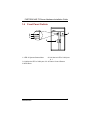
1
FASTORA NAS-T2 Hardware Installation Guide For service person only Disclaimers The information in this manual has been carefully checked and is believed to be accurate. AXIOMTEK Co., Ltd. assumes no responsibility for any infringements of patents or other rights of third parties, which may result from its use. AXIOMTEK assumes no responsibility for any inaccuracies that may be contained in this document. AXIOMTEK makes no commitment to update or to keep current the information contained in this manual. AXIOMTEK reserves the right to make improvements to this document and/or product at any time and without notice. No part of this document may be reproduced, stored in a retrieval system, or transmitted, in any form or by any means, electronic, mechanical, photocopying, recording, or otherwise, without the prior written permission of AXIOMTEK Co., Ltd. Copyright 2003 by AXIOMTEK Co., Ltd. All rights reserved. Version A2 May 2003 Printed in Taiwan ii Safety Approvals CE Marking FCC Class A FCC Compliance This equipment has been tested and complies with the limits for a Class A digital device, pursuant to Part 15 of the FCC Rules. These limits are designed to provide reasonable protection against harmful interference in a residential installation. If not installed and used in accordance with proper instructions, this equipment might generate or radiate radio frequency energy and cause harmful interference to radio communications. However, there is no guarantee that interference will not occur in a particular installation. If this equipment does cause harmful interference to radio or television reception, which can be determined by turning the equipment off and on, the user is encouraged to try to correct the interference by one or more of the following measurers: Reorient or relocate the receiving antenna. Increase the separation between the equipment and receiver. Connect the equipment into an outlet on a circuit different from that to which the receiver is connected. Consult the dealer or an experienced radio/TV technician for help. Shielded interface cables must be used in order to comply with emission limits. iii Safety Precautions Before getting started, read the following important cautions. 1. Be sure to ground yourself to prevent static charge when installing the internal components. Use a grounding wrist strap and place all electronic components in any static-shielded devices. Most electronic components are sensitive to static electrical charge. 2. Disconnect the power cords from the FASTORA NAS before making any installation. Be sure both the system and the external devices are turned OFF. Sudden surge of power could ruin sensitive components. Make sure the FASTORA NAS is properly grounded. 3. Do not open the system’s top cover. If opening the cover for maintenance is a must, only a trained technician is allowed to do so. Integrated circuits on computer boards are sensitive to static electricity. To avoid damaging chips from electrostatic discharge, observe the following precautions: Before handling a board or integrated circuit, touch an unpainted portion of the system unit chassis for a few seconds. This will help to discharge any static electricity on your body. When handling boards and components, wear a wrist-grounding strap, available from most electronic component stores. Trademarks Acknowledgments AXIOMTEK is a trademark of AXIOMTEK Co., Ltd. Other brand names and trademarks are the properties of their respective owners. iv Table of Contents Chapter 1 Introduction ----------------------- 1 1.1 1.2 1.3 1.4 1.5 1.6 General Description .......................................... 1 Standard Features ............................................. 3 System Specifications ...................................... 3 Dimensions ....................................................... 7 Rear Panel Outlets ............................................ 8 Front Panel Outlets ........................................... 9 Chapter 2 Installation Procedures --- 10 2.1 Preinstallation Checklist ................................. 10 2.1.1 Installing a hard-swappable hard drive ........10 Chapter 3 Starting the Appliance ------ 17 3.1 3.2 Hardware installation before starting the appliance ......................................................... 17 Appliance Indicators and Connectors ............ 18 3.2.1 3.2.2 3.2.3 3.2.4 3.2.5 3.3 Power control and reset buttons ..................18 Indicators of Ethernet control .......................19 Indicators of system status control LED ........20 Serial Port .......................................................20 Ethernet Port ..................................................21 The system board............................................ 22 3.3.1 Major components of the system board ......22 3.3.2 Keyboard Port (internal use) ..........................23 3.3.3 CRT VGA Port (internal use) ...........................23 3.4 Turn off the appliance ..................................... 23 Appendix A ---------------------------------------- 26 Warning..................................................................... 26 Table of Contents v This page does not contain any information. vi FASTORA NAS-T2 Server Hardware Installation Guide Chapter 1 Introduction This chapter states general information and detailed specifications of the FASTORA NAS-T2 Network Attached Storage server. Chapter 1 includes the following sections: General Mechanical Dimensions Description Features I/O Outlets System Specifications 1.1 General Description The FASTORA NAS-T2 server is designed for workgroup and solution providers those have networked storage requirements across heterogeneous Microsoft Windows 98, ME, NT4.0, 2000, XP, Novell Netware, Apple Introduction 1 FASTORA NAS-T2 Server Hardware Installation Guide Macintosh, and Linux, Solaris clients. It is a reliable and affordable, The server is a tower unit that requires only power and network connections for setup. The embedded RAID solution of Network Attached Storage (NAS) support RAID level 0, 1. The hot-swappable IDE hard disk drives provides highest availability and outstanding reliability. With its innovative mechanical and electrical design, the FASTORA NAS-T2 server provides high density, high scalability and high reliability in space-sensitive environments. The slim profile and large storage capacity provide highest price/performance ratio. With the cost-effective IDE disk drive design, the FASTORA NAS-T2 server delivers optimized performance, compared to the costly SCSI-based solutions. If any drive fails, data is secured by other drives and the system will alarm to the administrator automatically. The intelligent on-line data rebuilding capability of FASTORA NAS-T2 server allow you to hot swap a failed drive with automatically rebuilding data into the new drive without suffering from any system downtime while ensuring data integrity. The FASTORA NAS-T2 server support web-based management environment which provides excellent user-friendliness for the administrator to manage the server. 2 Introduction FASTORA NAS-T2 Server Hardware Installation Guide 1.2 Standard Features Tower unit design Hassle-free management via a browser interface or Windows -based (98/NT/2000/XP) setup utility for DHCP automatic IP assignment 24 x 7 fault-resilient storage appliance; Auto-notification alert system High-performance RAID at RAID 0, 1 with hotspare, on-line rebuild. 2 ATA-66/100 hot-swappable IDE HDD bays. Supports Microsoft Networks, Apple Networks, Novell Networks ( Bindery ) and UNIX Networks Double-byte language support for file name, user name, and security setting 1.3 System Specifications Hardware Form Factor: Tower unit design Capacity: From 0 to 500GB and beyond, depending on hard disk drive capacity. Power Supply: 200W ATX HRP power supplies Standard ATX power input connector Hard Drive: 2 x hot-swappable IDE HDD bays Rear Panel Connector: 1 x 10/100 Base-T Ethernet LAN port 1 x COM port 1 x Gigabit Ethernet LAN port Front Panel LED and Push-button: Introduction 3 FASTORA NAS-T2 Server Hardware Installation Guide 2 x LED for LANs 1 x LED for System/Alarm 1 x push-button for power on/off Processor: VIA C3 800MHz, FSB 133MHz BIOS: Award 2MB Flash BIOS Plug & Play L2 Cache: Built-in in CPU Main Memory: One PC133 SDRAM SODIMM up to 512MB IDE Interface: Support two bus mastering ATA 66/100 EIDE channels 4 Introduction FASTORA NAS-T2 Server Hardware Installation Guide Serial Port: One UART Ethernet: One 10/100 Base-T Ethernet and one optional Gigabit Ethernet Supporting fail-over Compact-FlashTM: One IDE interface CompactFlash TM socket for embedded system Dimensions: 120.9mm (W) x 183.0mm (H) x 265.8mm (D) Weight: Approx. 4kg with Power supplies, without any hard drive Operation environment: Air temperature: 10° C – 35°C (50°F – 95°F) Humidity: 10% – 95% Storage environment: Air temperature: -20° C – 65°C (-4°F – 149°F) Humidity: 10% – 95% Software Network Types/Network File Systems/Protocols/Clients Supported: Microsoft Network/ CIFS SMB / TCP/IP / Windows, 98,Me, NT 4.0, 2000,XP UNIX Network/ NFS v2.0 & v3.0 / TCP/IP / Red Hat Linux, Solaris, FreeBSD Novel Network/ BINDERY/ NCP / IPX / Novell IntraNetWare Clients for Windows Apple Macintosh Network/ AFP/ AppleTalk, TCP/IP / Apple Macintosh 7.x, 8.x, 9.x, OS X Domains Integration: Microsoft NT 4.0/2000 Domain include Active Directory Service NIS Domain Introduction 5 FASTORA NAS-T2 Server Hardware Installation Guide RAID Levels: RAID 0 RAID 1 Availability & Reliability: IDE hard disk hot swapping & on-line rebuilding External UPS support through serial port & SNMP trap Hardware (thermal, HD…) monitoring, auto-notification, and logging Manageability: Web-based Management (FASTORA Filer) for Microsoft Windows IE 5.0 and above SNMP MIB II support Multi-platform backup/restore support Data Replicator Other Features: Windows -based setup utility for DHCP automatic IP assignment for Microsoft Windows 98/NT/2000/XP Windows -based (Non-Windows -based) setup utility for DHCP automatic IP assignment for Microsoft IE 5.0 or above Double-byte language support RAID management Browser-based software update Restore default settings 6 Introduction FASTORA NAS-T2 Server Hardware Installation Guide 1.4 Dimensions Unit: mm Introduction 7 FASTORA NAS-T2 Server Hardware Installation Guide 1.5 Rear Panel Outlets Located at the rear panel of the FASTORA NAS-T2 server are the I/O outlets for connections of serial and Ethernet interface-supported devices. You could also locate the main power switch and cooling fans. The FASTORA NAS-T2 Server Rear Panel 4 5 6 3 2 1 1 COM Port #1 2 10/100 Ethernet port (LAN1) 3 Gigabit Ethernet port(LAN2) 4 FAN of Power Supply 5 A/C Inlet of Power Supply 6 Chassis FAN 8 Introduction FASTORA NAS-T2 Server Hardware Installation Guide 1.6 Front Panel Outlets 4 1 2 3 5 1 LED of System Status/Alert 2 Link/Active LED of LAN port #1 3 Link/Active LED of LAN port # 2 4 Power Control Button 5 HDD Door Introduction 9 FASTORA NAS-T2 Server Hardware Installation Guide Chapter 2 Installation Procedures 2.1 Preinstallation Checklist In addition to this installation guide, make sure you have the following items, The FASTORA NAS server appliance Power cord Utility CD (including this installation guide) Mounting screws for disk drive and screws used in this appliance for spare Hardware Installation Guide Quick installation guide FASTOR NAS Software User’s Manual If you ordered options for the appliance, this package might contain additional hardware or publications for those options. 2.1.1 Installing a hard-swappable hard drive The FASTORA NAS-T2 server has two hot-swappable drive bays, those can be installed 3.5” IDE hard drive each. You don’t’ need to turn off the appliance when replacing a failed hard drive. For each hot-swappable drive you plan to install, there must be a hot-swappable drive tray attached. The hard drive must be 3.5” ATA66/100/133 IDE compliance. The hot-swappable drive tray connects to the backplane. The backplane is the printed circuit board behind the bay. Attention: 1. Do not use any other drive tray which is not designed for this appliance, or a serious damage might cause. 10 Installation Procedures FASTORA NAS-T2 Server Hardware Installation Guide 2. For best flexibility, the appliance is designed to fit most types of hard drive form Hard disk drive vendors. But each of them might have slightly different mechanical dimension for installation, we strongly recommend use the same type hard drive or with the same dimension. Review the section 2.3 for more detail. Installation Procedures 11 FASTORA NAS-T2 Server Hardware Installation Guide To install a hard drive to a hot-swappable drive tray Figure 2.1.1.1 Figure 2.1.1.1 12 Installation Procedures FASTORA NAS-T2 Server Hardware Installation Guide Figure 2.1.1.1 螺絲(5X) Figure 2.1.1.2 Installation Procedures 13 FASTORA NAS-T2 Server Hardware Installation Guide Figure 2.1.1.3 Figure 2.1.1.3 14 Installation Procedures FASTORA NAS-T2 Server Hardware Installation Guide Figure 2.1.1.3 1. Open HDD door, press plastic locker trigger of tray downward to release tray handle.. See figure 2.1.1.1 2. Remove the empty hot-swappable drive tray by pulling the tray handle. Slide the tray off the tray bay. See figure 2.1.1.1 3. Disengage 4 screws that firmly mount the HDD drive onto the tray drive bay. Disconnected the cable of old or damage HDD drive from the tray backplane. Then, pull the HDD drive out of the tray drive bay. See figure 2.1.1.2 4. Mount the new HDD drive(s) into the empty slot. Connect the cable of tray backplane into new HDD. Affix the HDD drive by mounting 4 screws on each side of the drive bay. See figure 2.1.1.2 5. Gently push the hot-swappable drive tray into the hot-swappable drive bay until the tray connects to the backplane. 6. Push the drive tray handle toward to the close position. See figure 2.1.1.3. Installation Procedures 15 FASTORA NAS-T2 Server Hardware Installation Guide Check the hard drive status indicators to verify the drive is operating properly (see the figure 2.1.1.4) 1. When the HDD Yellow LED is continuously on, the drive is failed 2. When the HDD Yellow/green LED is off, the hot-swappable drive tray is in bad connection. 3. When the system green LED flashed slowing (one flash per two second), the drive is being rebuilding. 4. When the system green LED is continuously on, the drive is ready to use. 5. When the HDD green LED flash rapidly, the drive is accessing by host. Figure 2.1.1.4 16 Installation Procedures FASTORA NAS-T2 Server Hardware Installation Guide Chapter 3 Starting the Appliance Complete the installation by switching on the appliance, the power-on diagnostics run automatically. Each time the appliance is switched on; it runs a self-testing program to ensure that it is running correctly. After the power-on diagnostics running, the FASTORA NAS-T2 server starts to load the application and is ready for use. 3.1 Hardware installation before starting the appliance Before starting the appliance, you need to finish the hardware Installation. Please follow the following steps. (Review the chapter 2 for detail.) Step 1: Install HDD via hot-swappable drive tray to the drive bay. Note that All HDDs must be set to master or cable select mode Step 2: Connect the cable of Ethernet. Switched on the appliance after AC power cords are connected Step 3: The Yellow system LED is continuously at diagnostics status about 2 seconds, then the green system LED flash rapidly (one flash per 0.5 second) at the appliance is booting. Step 4: The continuous green LED means the appliance is ready. Step 5: Finish the hardware installation. Starting the Appliance 17 FASTORA NAS-T2 Server Hardware Installation Guide 3.2 Appliance Indicators and Connectors The FASTORA NAS-T2 server has the following indicators of control and connectors. 4 1 2 3 5 3.2.1 Power control and reset buttons 4 Power control button 1. When the A/C power cable is in socket, the appliance will start to initiate. 2. Press this button once to shutdown the appliance, and then press once again to switch on the appliance. Attention: 1. When the appliance is switched on, press this button continuously over 4 seconds to switch off the power directly. This switch-off activity should happen only when the appliance is hung; otherwise it may make the appliance non-operational or damage the drives. 2. It takes around 20 seconds for shutdown. 18 Starting the Appliance FASTORA NAS-T2 Server Hardware Installation Guide 3.2.2 Indicators of Ethernet control 2 Link/Active LED of LAN port # 1 1. This green LED is on when Ethernet port #1 in linking 100Mb speed connection. It flashes when there is transmit or receive activity to or from the appliance. 2. This Yellow LED is on when Ethernet port #1 in linking 10Mb speed connection. It flashes when there is transmit or receive activity to or from the appliance. 3 Link/Active LED of LAN port # 2 for Gigabit Lan 1. This green LED is on when Ethernet port #1 in linking 1000Mb speed connection. It flashes when there is transmit or receive activity to or from the appliance. 2. This Yellow LED is on when Ethernet port #1 in linking 100Mb speed connection. It flashes when there is transmit or receive activity to or from the appliance. Starting the Appliance 19 FASTORA NAS-T2 Server Hardware Installation Guide 3.2.3 Indicators of system status control LED 1 Green LED for system status 1. One flash per 0.5 second: when the appliance is booting. 2. One flash per 1.0 second: when the appliance is being shutdown. 3. One flash per 2.0 second: when the appliance is being re-building. 4. Always on: when the appliance is ready. Yellow LED for System alert 1. When appliance is booting, the Yellow LED will turn on for 1 second while BIOS is doing POST (power on self test), then the LED changes to green. 2. One flash per 1.0 second: when one or two Fans fail. Fan 1 is the CPU fan. Fan 2 is the chassis fan. 3. One flash per 2.0 second : when CPU over heating. 4. The Yellow LED is continuously on when the appliance is identified. The unique design for finding out the appliance quickly and makes it in control. This can be done by FASTORA Filer. 3.2.4 Serial Port The FASTORA NAS-T2 server uses a DB-9 connector for its serial port connection. The following table shows the pin assignments of this connector. 20 Starting the Appliance FASTORA NAS-T2 Server Hardware Installation Guide Pin # 1 2 3 4 5 6 7 8 9 Signal Name DCD, Data carrier detect RXD, Receive data TXD, Transmit data DTR, Data terminal ready GND, ground DSR, Data set ready RTS, Request to send CTS, Clear to send RI, Ring indicator 3.2.5 Ethernet Port The FASTORA NAS-T2 server provides two Ethernet (RJ-45) interfaces. For network connection, just plug in one cable-end of a 100-Base-T into the standard Ethernet phone jack. The pin assignment of the RJ-45 is listed below. RJ-45 Connector Pin Assignment Pin 1 2 3 6 others Description Tx+ (Data transmission positive) Tx- (Data transmission negative) Rx+(Data reception positive) Rx- (Data reception negative) Not use Starting the Appliance 8 76 5 4 3 21 21 FASTORA NAS-T2 Server Hardware Installation Guide 3.3 The system board 3.3.1 Major components of the system board 1 2 3 4 5 6 7 22 Power control Connector System/LAN status LED Connector CPU fan connector RTC jumper (short 1-2 at normal) Internal keyboard connector Internal CRT VGA Connector SODIMM socket Starting the Appliance FASTORA NAS-T2 Server Hardware Installation Guide 3.3.2 Keyboard Port (internal use) The FASTORA NAS-T2 server provides a keyboard connector for PS/2 type keyboard. Pin 1 2 3 4 Description 1 VCC for Keyboard Keyboard Data Ground for Keyboard Keyboard Clock 2 3 4 3.3.3 CRT VGA Port (internal use) The FASTORA NAS-T2 server provides a CRT VGA connector for video display. Pin 1 2 3 4 5 6 7 8 9 10 11 12 13 14 15 16 3.4 Description Red Signal VGA_GND Green Signal No Connection Blue Signal VGA_GND No Connection DDC_DATA GND VGA_GND GND HSYNC GND VSYNC DDC_CLOCK No Connection 1 15 2 16 Turn off the appliance There are two ways to turn off the FASTORA NAS-T2 Starting the Appliance 23 FASTORA NAS-T2 Server Hardware Installation Guide server. 1. When the appliance is running, you can turn off the appliance by pressing the power control button once. The appliance will shutdown automatically after around 20 seconds. Do not press the power button continuously for over 4 seconds, this action will turn off the power immediately. This may cause the appliance non-operational or corrupt the drives. 2. You might turn off (shutdown) the appliance via toolkits of FASTORA Filer. 24 Starting the Appliance FASTORA NAS-T2 Server Hardware Installation Guide This page does not contain any information. Starting the Appliance 25 FASTORA NAS-T2 Server Hardware Installation Guide Appendix A Warning This is a class A Product. In a domestic Environment this Product may cause radio interference in which case the user may be required to take adequate measures. It will be danger if battery is incorrectly replaced. Replacing only with the same or equivalent type is highly recommended by the manufacturer. Dispose of used batteries according to the manufacturer’s instructions. Warning for Hard Disk Drive Selection: TUV approved Hard Disk Drive is preferred for TUV compliance Hard Disk drive-Optional, (NWGQ2), generic, Input Voltage rated 5V dc/1.0A, 12V dc/1.8A maximum. Minimum clearance from uninsulated live parts 4.0 mm. Electric shock hazard inside the redundant power supply The exchange of modules shall be done by service person. 26 Warning FASTORA NAS-T2 Server Hardware Installation Guide This page does not contain any information. Warning 27