1
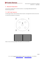
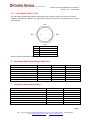
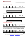
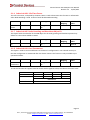
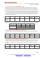
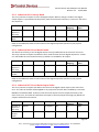
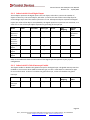
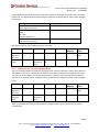
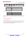
Control Devices CDJ CANopen User Manual Revision 1.3 22/10/2013 Unit 5, 79 Bourke Road, Alexandria NSW 2015 Australia, Phone +61 2 9330 1700 Fax: +61 2 8338 9001 E-mail: [email protected] Visit: www.controldevices.net This document and any information contained therein are confidential and the copyright of Control Devices Australia Pty Ltd and without infringement neither the whole nor any extract may be disclosed, loaned, copied or used for manufacturing or any other purpose whatsoever without their prior written consent and no liability is accepted for loss or damage from any cause whatsoever from the use of this document. Control Devices CDJ CANopen User Manual Revision 1.3 22/10/2013 Contents 1 Revision Table ....................................................................................................................................... 4 2 Definition of Terms ............................................................................................................................... 4 3 General Description .............................................................................................................................. 5 4 Features ................................................................................................................................................ 5 5 Electrical Connection ............................................................................................................................ 6 6 Recommended Operating Conditions................................................................................................... 7 7 Absolute Maximum Ratings .................................................................................................................. 7 8 Device Configuration............................................................................................................................. 8 9 8.1 SW1: Baud Rate Configuration ..................................................................................................... 8 8.2 SW2: Node Identifier Configuration ............................................................................................. 9 8.3 SW3: Termination Resistor Configuration .................................................................................... 9 8.4 J1 to J4: Disable Analogue Input ................................................................................................... 9 8.5 J5 to J7: Memory Mode .............................................................................................................. 10 8.6 J8: Operation Mode .................................................................................................................... 10 Object Dictionary ................................................................................................................................ 10 9.1 Service Data Objects ................................................................................................................... 10 9.1.1 Index 0x0005, 0x0006x and 0x0007: Dummy Objects ........................................................ 10 9.1.2 Index 0x1001: Error Register............................................................................................... 11 9.1.3 Index 0x1002: Status Register ............................................................................................. 11 9.1.4 Index 0x1008: Device Name................................................................................................ 11 9.1.5 Index 0x100C: Guard Time .................................................................................................. 11 9.1.6 Index 0x100D: Life Time Factor........................................................................................... 12 9.1.7 Index 0x100E: Node Guarding and Heartbeat Object ID .................................................... 12 9.1.8 Index 0x1010: Save Parameters .......................................................................................... 12 9.1.9 Index 0x1011: Load Default Parameters ............................................................................. 13 9.1.10 Index 0x1014: Emergency Message Object ID .................................................................... 13 9.1.11 Index 0x1015: Emergency Message Inhibit Time................................................................ 13 9.1.12 Index 0x1017: Heartbeat Time............................................................................................ 14 9.1.13 Index 0x2180: CAN Restart Time ........................................................................................ 14 9.2 Process Data Objects .................................................................................................................. 14 9.2.1 Communication Parameter Objects.................................................................................... 14 Page 2 Unit 5, 79 Bourke Road, Alexandria NSW 2015 Australia Phone +61 2 9330 1700 Fax: +61 2 8338 9001 E-mail: [email protected] Visit: www.controldevices.net Control Devices CDJ CANopen User Manual Revision 1.3 22/10/2013 9.2.2 9.3 PDO Mapping Objects ......................................................................................................... 16 Digital Output Objects................................................................................................................. 17 9.3.1 Index 0x6200: Write Digital Output .................................................................................... 17 9.3.2 Index 0x6202: Polarity Mask ............................................................................................... 18 9.3.3 Index 0x6206: Error Mode Enable ...................................................................................... 18 9.3.4 Index 0x6207: Error Mode Output Value ............................................................................ 18 9.4 Digital Input Objects ................................................................................................................... 19 9.4.1 Index 0x5003: Debounce Time............................................................................................ 19 9.4.2 Index 0x6000: Read Digital Input ........................................................................................ 20 9.4.3 Index 0x6005: Global Interrupt Enable ............................................................................... 20 9.4.4 Index 0x6006: Interrupt Mask: Any Change ....................................................................... 21 9.4.5 Index 0x6007: Interrupt Mask: Rising Edge ........................................................................ 21 9.4.6 Index 0x6008: Interrupt Mask: Falling Edge ....................................................................... 21 9.5 Analogue Input Objects............................................................................................................... 21 9.5.1 Index 0x5401: Dead Band Value ......................................................................................... 21 9.5.2 Index 0x6401: Read Analogue Input ................................................................................... 22 9.5.3 Index 0x6421: Interrupt Trigger Type ................................................................................. 23 9.5.4 Index 0x6423: Global Interrupt Enable ............................................................................... 23 9.5.5 Index 0x6424 to 0x6428: Interrupt Limits ........................................................................... 24 9.5.6 Index 0x6431: Input Offset................................................................................................. 24 10 Emergency Messages ...................................................................................................................... 24 11 Example Usage Scenarios................................................................................................................ 25 11.1 Default Settings ........................................................................................................................... 25 11.2 Send Message on Change ........................................................................................................... 26 11.3 Send Message on Change and Periodically................................................................................. 26 11.4 Send Message on Remote Transmission Request ...................................................................... 27 11.5 Send Message on Sync Signal ..................................................................................................... 27 Page 3 Unit 5, 79 Bourke Road, Alexandria NSW 2015 Australia Phone +61 2 9330 1700 Fax: +61 2 8338 9001 E-mail: [email protected] Visit: www.controldevices.net Control Devices CDJ CANopen User Manual Revision 1.3 22/10/2013 1 Revision Table Revision 1.0 1.1 1.2 Date 19/04/2012 25/05/2012 08/10/2013 Comment Document issued. Corrected formatting, added M12 connector. Corrected pin allocation on M12 connector. 2 Definition of Terms ms Millisecond, 0.001 seconds µs Microsecond, 0.000001 seconds Tx Transmit Rx Receive PDO Process Data Object COB ID CAN Object Identifier NMT Network Management message EMCY Emergency message SYNC Sync message RTR Remote Transmission Request 0b Prefix to denote a binary number 0x Prefix to denote a hexadecimal number Page 4 Unit 5, 79 Bourke Road, Alexandria NSW 2015 Australia Phone +61 2 9330 1700 Fax: +61 2 8338 9001 E-mail: [email protected] Visit: www.controldevices.net Control Devices CDJ CANopen User Manual Revision 1.3 22/10/2013 3 General Description The Control Devices CDJ CANopen is a multi-axis potentiometer joystick controller with CANopen output. The joystick offers the same compact size, strength and reliability as the Penny + Giles JC6000 and is available in one or two axis configuration with all handle options available on the standard Penny + Giles JC6000. 4 Features Long life potentiometer track Single or dual axis High strength lever with superb proportional control Configurable with all handle options available on Penny + Giles JC6000 Custom handles can be designed with up to 20 digital inputs, 4 proportional axes (including the joystick axes) and 4 digital outputs (up to 4 mA) 10 bit resolution of proportional axes Centre on and directional switches for each axis (directional switches consume a general purpose digital input) Memory function to freeze axis position on button input IP68 sealed connector Electrically isolated – power supply input can withstand 1.5kV transient voltage and CAN transceiver lines can withstand 5kV transient voltage. Page 5 Unit 5, 79 Bourke Road, Alexandria NSW 2015 Australia Phone +61 2 9330 1700 Fax: +61 2 8338 9001 E-mail: [email protected] Visit: www.controldevices.net Control Devices CDJ CANopen User Manual Revision 1.3 22/10/2013 5 Electrical Connection The joystick is available with a 5 pin M12 connector or a 4 pin Bulgin PX0413/04P 400 Series Buccaneer plug connector. 5.1 M12 5 pin Connector The M12 plug connector mates with M12 socket connectors. The figure below shows the connector as viewed from the bottom of the joystick. Pin 1 2 3 4 5 Function CAN SHIELD CAN +V CAN GND CAN H CAN L Refer to technical drawings supplied with joystick for more information. Page 6 Unit 5, 79 Bourke Road, Alexandria NSW 2015 Australia Phone +61 2 9330 1700 Fax: +61 2 8338 9001 E-mail: [email protected] Visit: www.controldevices.net Control Devices CDJ CANopen User Manual Revision 1.3 22/10/2013 5.2 4 pin Bulgin PX0413/04P The 4 pin Bulgin PX0413/04P 400 Series Buccaneer plug connector mates with socket connectors PX0410/S, PX0400/S or PX0402/S. The figure below shows the connector as viewed from the bottom of the joystick. Pin Function 1 +24 V Power 2 0 V GND 3 CANH 4 CANL Refer to technical drawings supplier with joystick for more information. 6 Recommended Operating Conditions Power Supply Voltage Power Supply Current CAN H Input Voltage CAN H Output Voltage CAN L Input Voltage CAN L Output Voltage Operating Temperature Min 18 V Typical 24 V 30 mA 4V 4.5 V -0.3 V Maximum 36 V 40 mA 5.3 V 1V 0.4 V +85°C -40°C 7 Absolute Maximum Ratings Minimum Power Supply Voltage CAN Input Voltage CAN Output Voltage CAN Output Current (Time < 20 ms) CAN Output Current General Purpose Output Current (Time < 20 ms) General Purpose Output Current -0.3 V -0.3 V Maximum 40 V 6V 6V 15 mA 4 mA 15 mA 4 mA Page 7 Unit 5, 79 Bourke Road, Alexandria NSW 2015 Australia Phone +61 2 9330 1700 Fax: +61 2 8338 9001 E-mail: [email protected] Visit: www.controldevices.net Control Devices CDJ CANopen User Manual Revision 1.3 22/10/2013 8 Device Configuration Three DIP switch banks and two jumper banks provide hardware configuration of the joystick. 8.1 SW1: Baud Rate Configuration DIP switch bank SW1 provides baud rate selection. Switch 4 is unused. On Off Baud Rate 1 2 3 4 Switch 1 Switch 2 Switch 3 1 Mbit/sec OFF OFF OFF 800 kbit/sec ON OFF OFF 500 kbit/sec OFF ON OFF 250 kbit/sec ON ON OFF 125 kbit/sec OFF OFF ON 50 kbit/sec ON OFF ON 20 kbit/sec OFF ON ON 10 kbit/sec ON ON ON Page 8 Unit 5, 79 Bourke Road, Alexandria NSW 2015 Australia Phone +61 2 9330 1700 Fax: +61 2 8338 9001 E-mail: [email protected] Visit: www.controldevices.net Control Devices CDJ CANopen User Manual Revision 1.3 22/10/2013 8.2 SW2: Node Identifier Configuration DIP switch bank SW2 configures the node identifier. The switch bank represents a 7-bit binary number, with switch 1 as the least significant bit and switch 7 as the most significant bit. Switch 8 is unused. On Off 1 2 3 4 5 6 7 8 Node Identifier Switch 7 Switch 6 Switch 5 Switch 4 Switch 3 Switch 2 Switch 1 Reserved 1 2 … 126 127 OFF OFF OFF OFF OFF OFF OFF OFF OFF OFF OFF OFF OFF OFF OFF OFF OFF ON OFF ON OFF ON ON ON ON ON ON ON ON ON ON ON ON OFF ON 8.3 SW3: Termination Resistor Configuration SW3 enables a 120 Ω resistor across the CAN data lines to electrically terminate the network. The resistor should be enabled if the device is at the end of the bus. Switch 2 is unused. On Off 1 2 Function Resistor disabled Resistor enabled Switch 1 OFF ON 8.4 J1 to J4: Disable Analogue Input These jumpers are used to disable unused analogue axes. Jumper 1 2 3 4 Axis X Y Z W Refer to the additional sheet for information specific to your joystick configuration. Page 9 Unit 5, 79 Bourke Road, Alexandria NSW 2015 Australia Phone +61 2 9330 1700 Fax: +61 2 8338 9001 E-mail: [email protected] Visit: www.controldevices.net Control Devices CDJ CANopen User Manual Revision 1.3 22/10/2013 8.5 J5 to J7: Memory Mode These jumpers are used to define the memory function of the device, which allows digital inputs to freeze the analogue input value. J7 1 Jumper J6 1 J5 1 1 1 0 1 0 1 1 0 0 0 1 1 Memory Description Mode 0 Push button input memory function with internal analogue value freeze. 1 Push button input memory function without internal analogue value freeze. 2 Switch input memory function with internal analogue value freeze. 3 Switch input memory function without internal analogue value freeze. 4 Memory function disabled. Refer to the additional sheet for information on the memory function specific to your joystick configuration. 8.6 J8: Operation Mode This jumper should be enabled for normal operation of the device. Disabling this jumper will enable a “special CAN features” mode provided for legacy systems that does not conform to the CANopen specification. 9 Object Dictionary 9.1 Service Data Objects 9.1.1 Index 0x0005, 0x0006x and 0x0007: Dummy Objects These objects are implemented to allow reservation of data space in PDOs by mapping to dummy entries. Name Index Sub-index Data Type Access RO RO PDO Mapping Yes Yes Default Value 0 0 Dummy 8 Dummy 16 0x0005 0x0006 0 0 Dummy 32 0x0007 0 Unsigned 8 Unsigned 16 Unsigned 32 RO Yes 0 Page 10 Unit 5, 79 Bourke Road, Alexandria NSW 2015 Australia Phone +61 2 9330 1700 Fax: +61 2 8338 9001 E-mail: [email protected] Visit: www.controldevices.net Control Devices CDJ CANopen User Manual Revision 1.3 22/10/2013 9.1.2 Index 0x1001: Error Register This object indicates an error in the device. Name Index Sub-index Data Type Access Error Register 0x1001 0 Unsigned 8 RO PDO Mapping Yes Default Value - An error is communicated by active bits; the error register bits have the following meaning: Bit 0 4 7 Meaning Generic error. This bit is set if any error is active. CAN bus or communication error. Device Error. 9.1.3 Index 0x1002: Status Register This object indicates the status of the device Name Index Sub-index Data Type Access Status Register 0x1002 0 Unsigned 32 RO PDO Mapping Yes Default Value - The device status is communicated by an active bit; the status register bits have the following meaning: Bit 30 31 Meaning Node guarding error. The device is operational. 9.1.4 Index 0x1008: Device Name This object holds the name of the device. Name Index Sub-index Data Type Access Device Name 0x1008 0 String RO PDO Mapping No Default Value - 9.1.5 Index 0x100C: Guard Time This object defines the Guard Time used for Node Guarding. The value of the object is a multiple of 1 ms, a value of 0 will disable Node Guarding. The device can use either Heartbeat or Node Guarding; do not use both protocols at the same time. Name Index Sub-index Data Type Access Guard Time 0x100C 0 Unsigned 16 RW PDO Mapping No Default Value 0 Page 11 Unit 5, 79 Bourke Road, Alexandria NSW 2015 Australia Phone +61 2 9330 1700 Fax: +61 2 8338 9001 E-mail: [email protected] Visit: www.controldevices.net Control Devices CDJ CANopen User Manual Revision 1.3 22/10/2013 9.1.6 Index 0x100D: Life Time Factor The Life Time Factor, multiplied by the Guard Time is used to determine the Life Time in milliseconds when Node Guarding is used. A value of 0 will disable Node Guarding. Name Index Sub-index Data Type Access Life Time Factor 0x100D 0 Unsigned 16 RW PDO Mapping No Default Value 0 9.1.7 Index 0x100E: Node Guarding and Heartbeat Object ID This object holds the identifier of the CAN object for the node guarding and heartbeat protocol. By default it is the node ID added to 0x700. Name Index Sub-index Data Type Access Guard COB ID 0x100E 0 Unsigned 32 RW PDO Mapping No Default Value 0x700 + Node ID 9.1.8 Index 0x1010: Save Parameters This object is used to store modifications to the device’s configuration in non-volatile memory so that the configuration is maintained after the device restarts. This function is only available in preoperational mode. Name Index Sub-index Data Type Access Save Parameters 0x1010 1 Unsigned 32 RW PDO Mapping No Default Value - To use this function the register must be written with a signature value, the value is the word “save”. MSB ASCII Hexadecimal Decimal e 0x65 LSB v a 0x76 0x61 0x65766173 1702257011 s 0x73 Page 12 Unit 5, 79 Bourke Road, Alexandria NSW 2015 Australia Phone +61 2 9330 1700 Fax: +61 2 8338 9001 E-mail: [email protected] Visit: www.controldevices.net Control Devices CDJ CANopen User Manual Revision 1.3 22/10/2013 9.1.9 Index 0x1011: Load Default Parameters This object is used to restore the factory default parameters of the device. Note that this is the factory default settings of the microcontroller used for CANopen communication and may differ from the original settings that were provided with the joystick. This function is only available in preoperational mode. After executing this function the device must be rest either by cycling the power or executing the NMT reset command. Once the device has booted the default configuration will be in use, however it will not be saved and therefore on subsequent resets the device will revert back to its last saved configuration. To save the configuration after loading default parameters see 9.1.8 Index 0x1010: Save Parameters. Name Index Sub-index Data Type Access Load Default Parameters 0x1011 1 Unsigned 32 RW PDO Mapping No Default Value - To use this function the register must be written with a signature value, the value is the word “load”. MSB ASCII Hexadecimal d 0x64 Decimal LSB a o 0x61 0x6f 0x64616f6c 1684107116 l 0x6c 9.1.10 Index 0x1014: Emergency Message Object ID This object holds the identifier for CAN emergency messages. By default it is the node ID added to 0x80. Name Index Sub-index Data Type Access EMCY COB ID 0x1014 0 Unsigned 32 RW PDO Mapping No Default Value 0x80 + Node ID 9.1.11 Index 0x1015: Emergency Message Inhibit Time This object defines the inhibit time for emergency messages; the minimum duration before a new emergency message can be sent. The value of the object is a multiple of 100 µs however the device only offers a resolution of 1 ms. A value of 0 in this object disables the inhibit time for emergency messages. Name Index Sub-index Data Type Access EMCY Inhibit Time 0x1015 0 Unsigned 16 RW PDO Mapping No Default Value 0 Page 13 Unit 5, 79 Bourke Road, Alexandria NSW 2015 Australia Phone +61 2 9330 1700 Fax: +61 2 8338 9001 E-mail: [email protected] Visit: www.controldevices.net Control Devices CDJ CANopen User Manual Revision 1.3 22/10/2013 9.1.12 Index 0x1017: Heartbeat Time This object defines the time between NMT heartbeat messages. The value of the object is a multiple of 1 ms, a value of 0 disables the heartbeat producer. The device can use either heartbeat or node guarding, do not use both protocols at the same time. Name Index Sub-index Data Type Access Heartbeat Time 0x1017 0 Unsigned 16 RW PDO Mapping No Default Value 0 9.1.13 Index 0x2180: CAN Restart Time This object defines the restart timeout for the CAN communication layer when the device transitions to the Bus Off state. The value of the object is a multiple of 1 ms. A value of 0 in this object will disable automatic restart of the device in the case of a Bus Off error state. Name Index Sub-index Data Type Access CAN Restart Time 0x2180 0 Unsigned 16 RW PDO Mapping No Default Value 0 9.2 Process Data Objects 9.2.1 Communication Parameter Objects Each PDO has an array to define parameters. Three PDOs are used by the device and the locations of the parameter arrays are: Index 0x1400 0x1800 0x1801 PDO RxPDO1 TxPDO1 TxPDO2 Description Digital Output PDO Parameters Digital Input PDO Parameters Analogue Input PDO Parameters The arrays all contain the same objects and the sub-indexes are: Name Largest Subindex Supported CAN Object ID Sub-index 0 Data Type Unsigned 8 Access RO PDO Mapping No Default Value 5 1 Unsigned 32 RW No Transmission Type Inhibit Time Reserved Event Time 2 Unsigned 8 RW No 0x200 + Node ID 255 3 4 5 Unsigned 16 Unsigned 16 RW RW No No No 0 0 9.2.1.1 Sub-index 0: Largest Sub-index Supported This object returns the number of objects in the structure. Page 14 Unit 5, 79 Bourke Road, Alexandria NSW 2015 Australia Phone +61 2 9330 1700 Fax: +61 2 8338 9001 E-mail: [email protected] Visit: www.controldevices.net Control Devices CDJ CANopen User Manual Revision 1.3 22/10/2013 9.2.1.2 Sub-index 1: CAN Object ID This object holds the object identifier for the PDO. By default it is the node ID added to 0x200. 9.2.1.3 Sub-index 2: Transmission Type This object is used to define the transmission configuration for the PDO. The value of the object defines the transmission type: Value 0 Type Acyclic Synchronous 1 – 240 Cyclic Synchronous 252 Synchronous RTR 253 Asynchronous RTR 254 Asynchronous 255 Asynchronous Description Message is transmitted on the SYNC signal only if data has changed. Message is transmitted on the SYNC signal; the value represents the number of SYNC signals before a message is transmitted. A value of 1 will transmit a message on every SYNC signal, a value of 2 will transmit a message on every second SYNC signal… etc. Data is updated on the SYNC signal but message is only sent on the reception of a Remote Transmission Request. Data is updated and message is sent on the reception of a Remote Transmission Request. CanEasy Mode for development. Message is transmitted immediately on any change, unless prohibited by Inhibit Time, and after Event Time. Message is transmitted immediately on any change, unless prohibited by Inhibit Time, and after Event Time. This transmission type should also be used for the receive PDO (the digital output). 9.2.1.4 Sub-index 3: Inhibit Time This object defines the inhibit time for the PDO messages; the minimum duration before a new message can be sent. The value of the object is a multiple of 100 ms and a value of 0 in this object will disable the inhibit time for the PDO. This object has no effect on the receive PDO. 9.2.1.5 Sub-index 4: Reserved This object is not used. 9.2.1.6 Sub-index 5: Event Time This object defines the event time for the PDO messages; the duration before a new message is sent. This setting only applies to PDO transmission type 254 or 255 as defined in sub-index 2 of the PDO parameter structure. A value of 0 will disable the event timer. This object has no effect on the receive PDO. Page 15 Unit 5, 79 Bourke Road, Alexandria NSW 2015 Australia Phone +61 2 9330 1700 Fax: +61 2 8338 9001 E-mail: [email protected] Visit: www.controldevices.net Control Devices CDJ CANopen User Manual Revision 1.3 22/10/2013 9.2.2 PDO Mapping Objects PDO Mapping Objects allow any mappable global object to be delivered in a PDO message. Each PDO has a structure to define PDO Mapping, the location of these structures are: Index 0x1600 0x1A00 0x1A01 PDO RxPDO1 TxPDO1 TxPDO2 Description Digital Output PDO Mapping Object Digital Input PDO Mapping Object Analogue Input PDO Mapping Object The structures all have the same format. The first sub-index defines the number of mapped objects in the PDO; subsequent sub-indexes contain the mapped objects. When changing the mapping of a PDO, sub-index 0 must first be set to 0 to disable mapping, then set to the correct number of mapped objects after remapping is complete. A maximum of 8 mapped objects in each PDO is possible. Name Number of Mapped Objects Mapped Object Sub-index 0 Data Type Unsigned 8 Access RW PDO Mapping No Default Value - 1 to 8 Unsigned 32 RW No - The Mapped Object sub-index is a 32 bit value that points to a mappable object. The structure of the sub-index is as follows: MSB Byte 3 Byte 2 Index of Mapped Object LSB Byte 1 Sub-index Byte 0 Length For example, to map the two joystick axis potentiometers into transmit PDO2 (the analogue input PDO) the PDO Mapping structure would be: Index 0x1a01 0x1a01 Sub-index 0 1 Value 2 0x64010110 0x1a01 2 0x64010210 Comment The structure contains two objects. Maps to analogue input 1; index: 0x6401, sub-index: 0x01, which has a length of 16 bits. Maps to analogue input 2; index: 0x6401, sub-index: 0x02, which has a length of 16 bits. Page 16 Unit 5, 79 Bourke Road, Alexandria NSW 2015 Australia Phone +61 2 9330 1700 Fax: +61 2 8338 9001 E-mail: [email protected] Visit: www.controldevices.net Control Devices CDJ CANopen User Manual Revision 1.3 22/10/2013 Another example, mapping the joystick axis directional switches and two handle push buttons into transmit PDO1 (the digital input PDO) would be: Index 0x1a00 0x1a00 Sub-index 0 1 Value 2 0x60000208 0x1a00 2 0x60000308 Comment The structure contains two objects. Maps to digital input byte 1; index: 0x6000, subindex: 0x02, which has a length of 8 bits. The 8 bits of this object are defined by the input from up to 8 directional switches; the object is further explained in 9.4 Digital Input Objects. Maps to digital input byte 2; index: 0x6000, subindex: 0x03, which has a length of 8 bits. The 8 bits of this object are defined by the input from up to 8 pushbuttons or switches; the object is further explained in 9.4 Digital Input Objects. All mappable objects, not just digital or analogue input or output, may be mapped into a PDO. The factory default configuration maps 1 digital output object, 3 digital input objects and 2 analogue inputs into PDOs. Refer to the additional sheet for the location of inputs in the PDO for your joystick configuration. 9.3 Digital Output Objects The following objects relate to the functionality of the digital outputs of the device, if used. 9.3.1 Index 0x6200: Write Digital Output This array contains the object to control the digital output. The first sub-index returns the number of objects in the array, the second sub-index in the writable byte to control the 8 digital outputs. Output lines are active low, so a value of 1 in a bit of the output object represents a grounding of the output pin, and value of 0 will set the pin to high level. Before writing to the output ports the value of the bitmap is processed with 9.3.2 Index 0x6202: Polarity Mask and inverted if necessary. Refer to the additional sheet for the location of the digital output bits specific to your joystick configuration. Name Index Sub-index Data Type Access RO PDO Mapping No Default Value 0x01 Number of Objects in the Array Write Digital Output 0x6200 0 Unsigned 8 0x6200 1 Unsigned 8 WO Yes 0 Refer to the additional sheet for the location of the digital output bits specific to your joystick configuration. Page 17 Unit 5, 79 Bourke Road, Alexandria NSW 2015 Australia Phone +61 2 9330 1700 Fax: +61 2 8338 9001 E-mail: [email protected] Visit: www.controldevices.net Control Devices CDJ CANopen User Manual Revision 1.3 22/10/2013 9.3.2 Index 0x6202: Polarity Mask This array contains an object to invert the digital outputs. When a change is made to the digital output object it is processed with the polarity mask and inverted if necessary. A value of 1 will invert the output bit. Name Index Sub-index Data Type Access RO PDO Mapping No Default Value 0x01 Number of Objects in the Array Polarity Mask 0x6202 0 Unsigned 8 0x6202 1 Unsigned 8 RW No 0 Refer to the additional sheet for the location of the digital output bits specific to your joystick configuration. 9.3.3 Index 0x6206: Error Mode Enable The device has a facility to set the digital outputs into a predefined state in the event of an error. This array contains an object to enable the error mode function for each digital output line. A value of 1 will enable the error mode function, by default it is enabled for all outputs. Name Index Sub-index Data Type Access RO PDO Mapping No Default Value 0x01 Number of Objects in the Array Error Mode Enable 0x6206 0 Unsigned 8 0x6206 1 Unsigned 8 RW No 0xff Refer to the additional sheet for the location of the digital output bits specific to your joystick configuration. 9.3.4 Index 0x6207: Error Mode Output Value This array contains an object that defines the value of the digital output object in the event of an error. The value of each bit will be applied to any output line that has been enabled by 9.3.3 Index 0x6206: Error Mode Enable. A value of 1 will force the output to active (output level low) in the event of an error, and value of 0 will force the output to inactive (output level high.) By default all outputs will be forced to inactive. Name Index Sub-index Data Type Access RO PDO Mapping No Default Value 0x01 Number of Objects in the Array Error Mode Output Value 0x6207 0 Unsigned 8 0x6207 1 Unsigned 8 RW No 0x00 Page 18 Unit 5, 79 Bourke Road, Alexandria NSW 2015 Australia Phone +61 2 9330 1700 Fax: +61 2 8338 9001 E-mail: [email protected] Visit: www.controldevices.net Control Devices CDJ CANopen User Manual Revision 1.3 22/10/2013 Refer to the additional sheet for the location of the digital output bits specific to your joystick configuration. 9.4 Digital Input Objects The following objects relate to the functionality of the digital inputs of the device, if available. Digital inputs are active low and the device has internal pull up resistors. 9.4.1 Index 0x5003: Debounce Time The device provides debounce filtering for each digital input line so that pushbuttons and switches can be connected without external filtering. The duration of the debounce filter can be set individually for each input line. The value of each object is the filter time in milliseconds, a value of 0 will disable the filtering function. Name Index Sub-index Data Type Access RO PDO Mapping No Default Value 0x18 Number of Digital Input Lines Filtering Time 0x5003 0 Unsigned 8 0x5003 1 to 24 Unsigned 8 RW No 40 Refer to the additional sheet for the location of the digital input bits specific to your joystick configuration. Page 19 Unit 5, 79 Bourke Road, Alexandria NSW 2015 Australia Phone +61 2 9330 1700 Fax: +61 2 8338 9001 E-mail: [email protected] Visit: www.controldevices.net Control Devices CDJ CANopen User Manual Revision 1.3 22/10/2013 9.4.2 Index 0x6000: Read Digital Input These objects represent the digital inputs. The first object, sub-index 0, returns the number of objects in the array. The second object, sub-index 1, returns the state of the internal flip-flops for each analogue input axis if the memory function is in use. Subsequent objects represent the digital inputs; the values of the objects are updated by the digital input lines. Input lines are active low, so a value of 1 in a bit of the input object represents a grounding of the input pin. Name Index Sub-index Data Type Access Number of Objects in the Array Memory Function Status for Each Axis Digital Input Byte 1 Digital Input Byte 2 Digital Input Byte 3 0x6000 0 Unsigned 8 RO PDO Mapping No 0x6000 1 Unsigned 8 RO Yes Default Value Depends on Operation Mode - 0x6000 2 Unsigned 8 RO Yes - 0x6000 3 Unsigned 8 RO Yes - 0x6000 4 Unsigned 8 RO Yes - Refer to the additional sheet for the location of the digital input bits specific to your joystick configuration. 9.4.3 Index 0x6005: Global Interrupt Enable This object enables or disables the global interrupt for the digital input. The global interrupt must be enabled to use an event driven PDO transmission type, see 9.2.1.3 Sub-index 2: Transmission Type for more information. A value of 1 enables the global interrupt; a value of 0 disables the global interrupt. Name Index Sub-index Data Type Access Global Interrupt Enable 0x6005 0 Unsigned 8 RW PDO Mapping No Default Value 0x01 Page 20 Unit 5, 79 Bourke Road, Alexandria NSW 2015 Australia Phone +61 2 9330 1700 Fax: +61 2 8338 9001 E-mail: [email protected] Visit: www.controldevices.net Control Devices CDJ CANopen User Manual Revision 1.3 22/10/2013 9.4.4 Index 0x6006: Interrupt Mask: Any Change This array of objects enables or disables the interrupt for any change of each digital input. If enabled an interrupt will be triggered for any change on the digital input line; a value of 1 enables the interrupt on any change, a value of 0 will disable it. The first sub-index returns the number of objects in the array; subsequent sub-indexes define the interrupt mask for each digital input byte. The default value enables the interrupt on any change for all digital inputs. Name Index Sub-index Data Type Access Number of Objects in the Array Digital Input Byte 1 Digital Input Byte 2 Digital Input Byte 3 0x6006 0 Unsigned 8 RO PDO Mapping No 0x6006 1 Unsigned 8 RW No Default Value Depends on Operation Mode 0Xff 0x6006 2 Unsigned 8 RW No 0xff 0x6006 3 Unsigned 8 RW No 0xff Refer to the additional sheet for the location of digital input bits specific to your joystick configuration. 9.4.5 Index 0x6007: Interrupt Mask: Rising Edge This array has a similar function and structure to 9.4.4 Index 0x6006: Interrupt Mask: Any Change but will only generate interrupts on the rising edge of the input. As the input becomes active an interrupt will trigger, as it becomes inactive an interrupt will not be triggered. The default value of the objects in the array is 0x00; interrupt on rising edge is disabled. 9.4.6 Index 0x6008: Interrupt Mask: Falling Edge This array has a similar function and structure to 9.4.4 Index 0x6006: Interrupt Mask: Any Change but will only generate interrupts on the falling edge of the input. As the input becomes inactive an interrupt will trigger, as it becomes active an interrupt will not be triggered. The default value of the objects in the array is 0x00; interrupt on falling edge is disabled. 9.5 Analogue Input Objects The following objects relate to the functionality of the analogue inputs of the device. 9.5.1 Index 0x5401: Dead Band Value This array of objects defines the dead band for each axis. The first sub-index returns the number of objects in the array; subsequent objects define the dead band value for each analogue input. If the analogue input is within the dead band (greater than the negative of the dead band value and less than the dead band value,) the value of 9.5.2 Index 0x6401: Read Analogue Input for that input will be 0x0000. If the analogue input is less than the negative of the dead band value, the value of 9.5.2 Index 0x6401: Read Analogue Input for that input will be the analogue input value plus the dead band value. Similarly, if the analogue input is greater than the dead band value, the value of 9.5.2 Page 21 Unit 5, 79 Bourke Road, Alexandria NSW 2015 Australia Phone +61 2 9330 1700 Fax: +61 2 8338 9001 E-mail: [email protected] Visit: www.controldevices.net Control Devices CDJ CANopen User Manual Revision 1.3 22/10/2013 Index 0x6401: Read Analogue Input for that input will be the analogue input value minus the dead band value. The following table summarises the calculation to determine the value of the analogue input object: Analogue Input Value A1 < -DB1 (Axis negative position) A1 > -DB1 AND A1 < DB1 (Within dead band) A1 > DB1 (Axis positive position) Analogue Input Object AO1 = A1 + DB1 AO1 = 0x0000 AO1 = A1 - DB1 The default value for each dead band object is 0x1000. Name Index Sub-index Data Type Access RO PDO Mapping No Default Value Number of Axes Number of Objects in the Array Dead Band Value 0x5401 0 Unsigned 8 0x5401 1 to Number of Axes Unsigned 16 RW No 0x1000 9.5.2 Index 0x6401: Read Analogue Input This array contains objects to read each analogue input. The first sub-index contains the number of sub-indexes in the array; subsequent sub-indexes contain the result from the analogue input lines. The values of these objects are a signed 16 bit integer; a positive value corresponds to a positive position of the analogue input, a negative value corresponds to a negative position of the analogue input. Name Index Sub-index Data Type Access RO PDO Mapping No Default Value Number of Axes Number of Objects in the Array Read Analogue Input 0x6401 0 Unsigned 8 0x6401 1 to Number of Axes Signed 16 RO Yes - Refer to the additional sheet for the location of analogue input objects specific to your joystick configuration. Page 22 Unit 5, 79 Bourke Road, Alexandria NSW 2015 Australia Phone +61 2 9330 1700 Fax: +61 2 8338 9001 E-mail: [email protected] Visit: www.controldevices.net Control Devices CDJ CANopen User Manual Revision 1.3 22/10/2013 9.5.3 Index 0x6421: Interrupt Trigger Type This array contains objects to set the type of events that will trigger an interrupt for each analogue input. The first sub-index returns the number of sub-indexes in the array; subsequent sub-indexes contain a bitmap to set trigger types as show below: Bit 0 1 2 3 4 5 to 7 Interrupt Trigger Type Input voltage greater than Upper Limit Input voltage less than Lower Limit Input changed more than Delta Input decreased more than Negative Delta Input increased more than Positive Delta Reserved (must be forced to 0) The default value for each axis’ interrupt trigger type is 7, which enables the first three interrupt trigger types. Limit values are defined in 9.5.5 Index 0x6424 to 0x6428: Interrupt Limits. Name Index Sub-index Data Type Access RO PDO Mapping No Default Value Number of Axes Number of Objects in the Array Interrupt Trigger Type 0x6421 0 Unsigned 8 0x6421 1 to Number of Axes Unsigned 8 RW No 7 9.5.4 Index 0x6423: Global Interrupt Enable This object controls the global interrupt for the analogue inputs. By default the interrupt is disabled to avoid excessive transmission of analogue input values. A value of 1 enables the global interrupt for the analogue input; a value of 0 will disable it. Name Index Sub-index Data Type Access Global Interrupt Enable 0x6423 0 Unsigned 8 RW PDO Mapping No Default Value 0 Page 23 Unit 5, 79 Bourke Road, Alexandria NSW 2015 Australia Phone +61 2 9330 1700 Fax: +61 2 8338 9001 E-mail: [email protected] Visit: www.controldevices.net Control Devices CDJ CANopen User Manual Revision 1.3 22/10/2013 9.5.5 Index 0x6424 to 0x6428: Interrupt Limits There a several arrays of objects to define interrupts limits, these objects all have an identical structure. The function of each array is: Index 0x6424 Name and Function Upper Limit Value – Generate interrupt if input voltage is greater than limit value. Lower Limit Value – Generate interrupt if input voltage is less than limit value. Delta Value – Generate interrupt if input voltage changes by more than delta value. Negative Delta Value – Generate interrupt if voltage reduced by more than negative delta value. Positive Delta Value – Generate interrupt if voltage increased by more than positive delta value. 0x6425 0x6426 0x6427 0x6428 The structure of each array is: Name Index Sub-index Data Type Access RO PDO Mapping No Default Value Number of Axes Number of Objects in the Array Interrupt Trigger Type 0x642_ 0 Unsigned 8 0x642_ 1 to Number of Axes Signed 32 RW No 0 9.5.6 Index 0x6431: Input Offset This array contains objects to define the input offset for each axis. The input offset value is added to 9.5.2 Index 0x6401: Read Analogue Input. By default the analogue input value is positive and negative with 0 at the centre, if only positive values are required an input offset of 0x8000 can be used. Name Index Sub-index Data Type Access RO PDO Mapping No Default Value Number of Axes Number of Objects in the Array Input Offset 0x6431 0 Unsigned 8 0x6431 1 to Number of Axes Signed 32 RW No 0 10 Emergency Messages The device supports several emergency messages; the Object ID for these messages is 0x80 + Node ID. The structure of the message is: Byte Page 24 Unit 5, 79 Bourke Road, Alexandria NSW 2015 Australia Phone +61 2 9330 1700 Fax: +61 2 8338 9001 E-mail: [email protected] Visit: www.controldevices.net Control Devices CDJ CANopen User Manual Revision 1.3 22/10/2013 0 1 EMCY Code 2 Error Register 3 0 4 5 6 Device Error Code 7 A description of each section is given below: EMCY Code Error Register Device Error Code Emergency error code according to DS310. The contents of the Error Register, index 0x1001. An unsigned 32 bit value to indicate error type. A list of device error codes is given below: Device Error Code 0x80000000 0x40000000 0x30000000 Description CAN Bus in Bus Off state. CAN Bus in error warning state. Life Guarding error. In the event of multiple errors the error codes are combined in a logical OR operation. Be aware that some error conditions can cause a change of NMT state and/or force output pins into their error state. 11 Example Usage Scenarios 11.1 Default Settings The factory default settings will send a message on any change of the digital output, but no message will be sent on analogue input change. There are 2 analogue inputs (generally X and Y axis of the joystick,) and 24 digital inputs mapped into PDO objects. Refer to the additional sheet for the location of inputs specific to your joystick configuration. Page 25 Unit 5, 79 Bourke Road, Alexandria NSW 2015 Australia Phone +61 2 9330 1700 Fax: +61 2 8338 9001 E-mail: [email protected] Visit: www.controldevices.net Control Devices CDJ CANopen User Manual Revision 1.3 22/10/2013 11.2 Send Message on Change This configuration will send data on any change of the digital inputs and on any change of the analogue inputs, no more frequently than the inhibit time of 10 ms. Operation Index Type Value Description 0x1011 Subindex 1 Write SDO u32 0x64616f6c Write SDO 0x1801 3 u16 0x64 Write SDO 0x6423 0 u8 0x1 Write SDO 0x1010 1 u32 0x65766173 Load factory defaults; the following instructions assume you are starting from factory defaults. You will need to reset the device to complete the operation. See 9.1.9 Index 0x1011: Load Default Parameters Set Inhibit Time for analogue input PDO to 10 ms. See 9.2.1.4 Sub-index 3: Inhibit Time Enable global interrupt on analogue input. See 9.5.4 Index 0x6423: Global Interrupt Enable Save current configuration so that the configuration is maintained after the device is restarted. See 9.1.8 Index 0x1010: Save Parameters Set device to operational mode. NMT Start 11.3 Send Message on Change and Periodically In addition to the previous commands in 11.2 Send Message on Change the following commands can be used to also send messages periodically, after the event time of 100 ms. Operation Index Type Value Description 0x1800 Subindex 5 Write SDO u16 0x3EB Write SDO 0x1801 5 u16 0x3EB Write SDO 0x1010 1 u32 0x65766173 Set Event Time for digital input PDO to 100 ms. See 9.2.1.6 Sub-index 5: Event Time Set Event Time for analogue input PDO to 100 ms. See 9.2.1.6 Sub-index 5: Event Time Save current configuration so that the configuration is maintained after the device is restarted. See 9.1.8 Index 0x1010: Save Parameters Set device to operational mode. NMT Start Page 26 Unit 5, 79 Bourke Road, Alexandria NSW 2015 Australia Phone +61 2 9330 1700 Fax: +61 2 8338 9001 E-mail: [email protected] Visit: www.controldevices.net Control Devices CDJ CANopen User Manual Revision 1.3 22/10/2013 11.4 Send Message on Remote Transmission Request This configuration with update and send data on reception of a Remote Transmission Request. Operation Index Type Value Description 0x1011 Subindex 1 Write SDO u32 0x64616f6c Write SDO 0x1800 2 u8 0xFD Write SDO 0x1801 2 u8 0xFD Write SDO 0x1010 1 u32 0x65766173 Load factory defaults; the following instructions assume you are starting from factory defaults. You will need to reset the device to complete the operation. See 9.1.9 Index 0x1011: Load Default Parameters Set transmission type for digital input to Asynchronous RTR. See 9.2.1.3 Sub-index 2: Transmission Type Set transmission type for analogue input to Asynchronous RTR. See 9.2.1.3 Sub-index 2: Transmission Type Save current configuration so that the configuration is maintained after the device is restarted. See 9.1.8 Index 0x1010: Save Parameters Set device to operational mode. NMT Start 11.5 Send Message on Sync Signal This configuration will send a message for each PDO every time a sync signal is received. Operation Index Type Value Description 0x1011 Subindex 1 Write SDO u32 0x64616f6c Write SDO 0x1800 2 u8 0x01 Write SDO 0x1801 2 u8 0x01 Write SDO 0x1010 1 u32 0x65766173 Load factory defaults; the following instructions assume you are starting from factory defaults. You will need to reset the device to complete the operation. See 9.1.9 Index 0x1011: Load Default Parameters Set transmission type for digital input to Cyclic Synchronous with a multiplier of 1. See 9.2.1.3 Sub-index 2: Transmission Type Set transmission type for analogue input to Cyclic Synchronous with a multiplier of 1. See 9.2.1.3 Sub-index 2: Transmission Type Save current configuration so that the configuration is maintained after the device is restarted. See 9.1.8 Index 0x1010: Save Parameters Set device to operational mode. NMT Start Page 27 Unit 5, 79 Bourke Road, Alexandria NSW 2015 Australia Phone +61 2 9330 1700 Fax: +61 2 8338 9001 E-mail: [email protected] Visit: www.controldevices.net