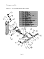
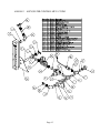
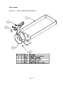
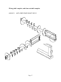
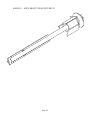
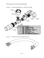
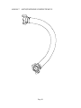
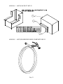
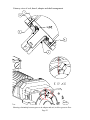
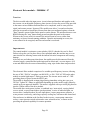
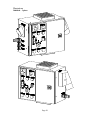
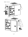
1
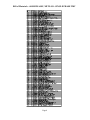
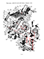
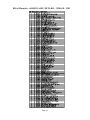
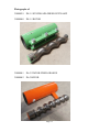
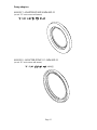
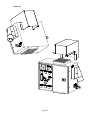
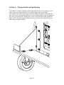
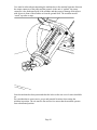
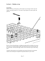
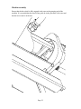
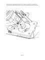
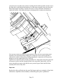
MP-25 User Manual
60010120
ASSY, MP 25-SO - SINGLE PHASE 220V
60010121
ASSY, MP 25-HO - 3 PHASE - 220V
60010122
ASSY, MP 25-SO - 3 PHASE - 220V
Revision - – 10/03/2008
620 County Road 4841, Haslet, TX 76052
Ph 817.439.1108 Fax 817.439.0633
www.machine-technologies.com
Dear Customer,
Before starting this machine please complete the following;
Machine Date of purchase…………………………………..
Machine serial number………………………………………
Please read the following information contained within this manual and fully familiarize
yourself with the equipment.
Page 2
Contents
Page
Section 1 - General Safety information................................................................................................................ 4
Danger................................................................................................................................................................ 4
Section 2 - Machine Description........................................................................................................................... 5
Function ............................................................................................................................................................. 5
Machine illustrations ........................................................................................................................................ 6
Photographs................................................................................................................................................... 6
Illustration – 60010120 ASSY, MP 25-SO - SINGLE PHASE 220V ........................................................ 7
Bill of Materials – 60010120 ASSY, MP 25-SO - SINGLE PHASE 220V................................................ 7
Bill of Materials – 60010120 ASSY, MP 25-SO - SINGLE PHASE 220V................................................ 8
Illustration – 60010121 ASSY, MP 25-HO - 3 PHASE - 220V .................................................................. 9
Bill of Materials – 60010121 ASSY, MP 25-HO - 3 PHASE - 220V........................................................ 10
Photographs of ............................................................................................................................................ 11
30000039
D8-1.5 STATOR-ADJ-GREEN-INTCLAMP ............................................................. 11
30000040
D8-1.5 ROTOR .............................................................................................................. 11
30000041
D6-3 STATOR-FIXED-ORANGE ............................................................................... 11
30000042
D6-3 ROTOR ................................................................................................................. 11
30000043
D4-3 STATOR-FIXED-GREEN................................................................................... 12
30000044
D4-3 ROTOR ................................................................................................................. 12
30000045
R8-1.5 STATOR-ADJ-BLACK-INTCLAMP\ ............................................................ 12
30000046
R8-1.5 ROTOR .............................................................................................................. 12
Pump adapters ............................................................................................................................................ 13
44010257- ADAPTER,PUMP 90MM-MP-25 ....................................................................................... 13
44010258 - ADAPTER,PUMP 113.5MM-MP-25 ................................................................................. 13
Water plate assemblies ............................................................................................................................... 14
60010136
ASSY,WATER CONTROL MP-25-4GPM ................................................................. 14
60010142
ASSY,WATER CONTROL MP-25-7GPM ................................................................. 15
Motor mount ............................................................................................................................................... 16
60010134
ASSY,UPPER MTR MNT MP-25................................................................................ 16
Mixing shaft complete, and clean out shaft complete .............................................................................. 17
60010125
ASSY, DRIVE/MIX SHAFT MP-25 ............................................................................ 17
60010126
ASSY, SHAFT CLEAN OUT-MP-25........................................................................... 18
Water pressure tester, water hoses and fan duct ..................................................................................... 19
60010140
TESTER,WATER PRESS - 35MM-MALE-600PSI................................................... 19
60010139
ASSY WATER HOSE-COMPLETE-MP-25 .............................................................. 19
60010147
ASSY,PUMP HOSE COMPLETE MP-25 .................................................................. 20
60010144
ASSY,FAN DUCT MP-25 ............................................................................................. 21
60010148
ASSY,WASHDOWN HOSE COMPLETE MP-25 ..................................................... 21
Electric Drive unit....................................................................................................................................... 22
Typical layout.......................................................................................................................................... 22
Cutaway view of seal, dowel, adapter and shaft arrangement............................................................ 23
Electronic Drive module – 20000046 / 47 .................................................................................................. 24
Function................................................................................................................................................... 24
Illustrations ............................................................................................................................................. 26
Section 3 – Transportation and positioning ...................................................................................................... 29
Section 4 – Machine set up.................................................................................................................................. 31
Unpacking ........................................................................................................................................................ 31
Machine assembly ........................................................................................................................................... 32
Electrical connections. .................................................................................................................................... 35
Pre-run setting and test .................................................................................................................................. 36
Section 5 – Machine operation / stator pressure setting................................................................................... 37
General notes for operation............................................................................................................................ 39
Section 6 – Simple maintenance ......................................................................................................................... 40
Clean out shaft – using.................................................................................................................................... 41
Section 7 – Notes on wear of rotor stator pump unit........................................................................................ 42
Wear issues ...................................................................................................................................................... 42
Dry running of a rotor-stator pump.......................................................................................................... 42
LIMITED WARRANTY POLICY................................................................................................................... 43
Page 3
Section 1 - General Safety information
Danger
Follow these instructions very carefully, in order to avoid injury to yourself or others.
Electrically powered machine.
Always ensure that all power to the machine has been turned off and isolated before
ANY maintenance / repair work is carried out on the machine.
Ensure that all guards are correctly fitted before starting or attempting to operate the
machine.
Ensure that all fasteners are present and correctly fitted before attempting to start or
operate the machine.
Ensure that the pump unit is correctly fastened to the front of the hopper unit of the
machine, and free of damage before attempting to start or operate the machine.
Ensure that the main electric drive motor assembly, are secured to the rear of the hopper
and clamped in place and free from damage before attempting to start or operate the
machine.
The MP-25 mixing pump unit can produce high pressures, high torques and can use high
voltages. Care must be taken by all users. Only authorized and trained persons should
work with this machine.
Page 4
Section 2 - Machine Description
Function
The MP-25 is a mixing pump.
The machine has a drive motor, that turns a drive shaft within a material hopper that in
turn feeds material through a mixing / hydration chamber to a progressive cavity rotor
stator pump unit that delivers the material from the hopper to the dispense head or
otherwise via a material hose / hoses.
The machine is driven by an electric motor powered by 220VAC 3 phase 50/60Hz, via
an electronic variable speed inverter supplied by two phase (commonly called single
phase) OR three phase 208/240VAC 50/60 Hz grounded electrical supply.
All styles of drives transmit their rotary action through a drive shaft equipped with bridge
breakers, and metering flights, which convey the material from the hopper into the
mixing / hydration chamber, where surface hardened mixing arms mix and shear the
material with water, towards the pump unit, where further mixing occurs.
The pump unit is a progressive cavity pump unit comprising of a helical rotating “rotor”
with the rubber lined “stator”. As the rotor rotates, material is drawn / fed into open
rubber cavities, which then transform into “pockets”. The series of cavities, then move
from one end of the stator to the other as the rotor turn with respect to the stationary
stator, causing the material to be conveyed from the hopper towards the outlet.
Once the material has reached the outlet it is guided through an output flange assembly,
into the dispense hose through to the hose outlet, where typically a spray nozzle is
attached allowing, with the assistance of an auxiliary air supply, the material to be
“sprayed” on to the substrate, or simply allowed to discharge from the end of the hose.
A number of different devices can be fitted to the outlet of the tube for different means of
application. For details of these different devices please contact your supplier of
Machine-Technologies equipment or Machine-Technologies directly.
The primary difference between the three models is the combination of, rotor stator size
(D or R style), water flow meter capacity (4 GPM or 7 GPM), and motor HP (5.4 or 7.5).
Page 5
Machine illustrations
Photographs
Single phase,
STD output,
unit shown
Page 6
Illustration – 60010120 ASSY, MP 25-SO - SINGLE PHASE 220V
Page 7
Bill of Materials – 60010120 ASSY, MP 25-SO - SINGLE PHASE 220V
Page 8
Illustration – 60010121 ASSY, MP 25-HO - 3 PHASE - 220V
Page 9
Bill of Materials – 60010121 ASSY, MP 25-HO - 3 PHASE - 220V
Page 10
Photographs of
30000039
D8-1.5 STATOR-ADJ-GREEN-INTCLAMP
30000040
D8-1.5 ROTOR
30000041
D6-3 STATOR-FIXED-ORANGE
30000042
D6-3 ROTOR
Page 11
30000043
D4-3 STATOR-FIXED-GREEN
30000044
D4-3 ROTOR
30000045
R8-1.5 STATOR-ADJ-BLACK-INTCLAMP\
30000046
R8-1.5 ROTOR
Page 12
Pump adapters
44010257- ADAPTER,PUMP 90MM-MP-25
(to suit “D” series rotors and stators)
44010258 - ADAPTER,PUMP 113.5MM-MP-25
(to suit “R” series rotors and stators)
Page 13
Water plate assemblies
60010136
ASSY,WATER CONTROL MP-25-4GPM
Page 14
60010142
ASSY,WATER CONTROL MP-25-7GPM
Page 15
Motor mount
60010134
ASSY,UPPER MTR MNT MP-25
Page 16
Mixing shaft complete, and clean out shaft complete
60010125
ASSY, DRIVE/MIX SHAFT MP-25
Page 17
60010126
ASSY, SHAFT CLEAN OUT-MP-25
Page 18
Water pressure tester, water hoses and fan duct
60010140
TESTER,WATER PRESS - 35MM-MALE-600PSI
60010139
ASSY WATER HOSE-COMPLETE-MP-25
Page 19
60010147
ASSY,PUMP HOSE COMPLETE MP-25
Page 20
60010144
ASSY,FAN DUCT MP-25
60010148
ASSY,WASHDOWN HOSE COMPLETE MP-25
Page 21
Electric Drive unit
Typical layout
Shown in cutaway view of upper motor mount. Unit must be greased on a daily / job-byjob basis.
Page 22
Cutaway view of seal, dowel, adapter and shaft arrangement
Showing relationship between grooves in adaptor and seal, to allow grease to flow
Page 23
Electronic Drive module – 20000046 / 47
Function
The drive module takes the input power via an isolator and breakers and supplies to the
drive motor via an adjustable frequency phase inverter. Prior to the power being provided
to the motor various addition functions have to be completed, such as water pressure
signal, and remote present / bypassed. The module runs after a 2 second acceleration
period at an operator selected speed chosen from three preconfigured options, when the
“Start” button is pressed either on the panel or on the remote. The unit decelerates to zero
RPM following the “stop” button being pressed on either the panel or the remote.
Whenever the reverse switch is actuated, the unit will turn in reverse, either from
stationary or from a forward running condition. Upon the unit turning in reverse, the
water solenoid is de-energized, until forward motion is reselected.
Important note.
The control module is resistant to water splashes, ONLY when the fan cowl is fitted.
Failure to keep the cowl in place allows water splashed under the machine top cover to
enter into the box allowing contact with the internal electrical components and causing
damage.
After each use and subsequent clean down, the module must be disconnected from the
electrical supply, opened and the inside inspected for debris and / or water ingress. ALL
water and debris must be removed immediately, using wipe clothes then compressed air.
The electronic Drive module comprises of a variable speed frequency inverter, allowing
the use of 208 / 220VAC two phase, on 60010120 , or 208 / 220VAC 3PH on the other
models to run the high torque 3 Phase gear motor. The inverter unit is rated at 7.5 HP
providing plenty of power to run the MP-25 unit.
The module is supplied with an input plug allowing immediate wiring into your own
220VAC 2 phase or 3 Phase (as applicable depending up on the model) supply (Must be
carried out by an approved installer). The motor is supplied with a pre-wired plug that fits
into the 3 Phase outlet of the drive module.
The module has a main power isolator, a combined stop / start switch, a spring loaded
reverse switch, a speed control (three speed positions), a series of indicator lights, an
inverter drive, internal breakers for each input phase, a water pump motor contactor, a
water pressure switch relay, and a large capacity cooling fan, with removable shroud and
filter enclosure, in addition to the fan fitted to the inverter, a water pump connection
socket, a water pressure switch socket and a water solenoid socket, a remote socket
providing the optional capability for remote operation.
Page 24
Single-phase drive module
The Single-phase drive module, in addition to the previously mentioned items is
equipped with an inverter error signal light, which illuminates if the inverter goes into
overload for example.
The three phase unit has a phase detection module with prevents the power from coming
on unless the phases are wired to run the unit in the correct direction. To correct the
wiring there is a phase reversal switch on the front panel of the three phase units in place
of the inverter error indicator on the single-phase unit.
Fixed to the sides of the control module are a series of polarized plugs, each is color
coded to suit the mating socket.
Each machine is equipped with a water pump, used as a booster pump to help ensure
consistent water pressure, and as such the unit will not run unless the water pressure
switch is closed. For maintenance the water pressure switch can be over ridden using the
supplied “dummy” plug, attached to the side of the module.
Each machine is equipped with a water supply module which is operated by a signal from
the control module to open and close a solenoid valve which starts and stops the water
flow.
Each machine is supplied with a wired remote pendant, allowing the operation of the
machine from up to 10 feet from the connection. The remote provides stop / start
functionality only. The machine will NOT run without either the remote being attached,
or the remote “dummy” plug being attached, the “dummy” plug is attached to the side of
the module and color coded similarly to the water pressure “dummy” plug
Page 25
Illustrations
20000046 – 3 phase
Page 26
20000047 – single phase
Page 27
With cowl
Page 28
Section 3 – Transportation and positioning
The machine is typically manually transported around the job site using the two swivel
casters at the rear of the machine to steer, with the larger wheels at the front.
The machine can be picked up using a forklift, by simply inserting the forks under the
base from the rear, and ensuring that they are close enough together to prevent damage to
the casters. Each caster has a locking lever, which, when in the horizontal position the
brake is OFF, and when angled in either direction are locked. Ensure that the locks are
OFF when moving the machine.
Page 29
Care must be taken when transporting the machine due to the minimal clearance between
the output connector of the pump and the ground. As the unit is “pushed” the pump
connector is the furthermost pint of the machine and thus prone to damage from impact
with objects in front of the machine or from the ground itself. The machine must be
“eased” up curbs or steps.
Once the machine has been positioned then the locks on the rear swivel casters should be
set.
Pay consideration to water source, power and material locations when setting the
machine in position. The site must be flat and level to ensure that the machine operates
from a horizontal position.
Page 30
Section 4 – Machine set up
Unpacking
Remove the safety grid from the top of the machine by removing the 4 bolts, clips and
washers, using the provided 7/16” AF wrench . Keep all parts to be used to replace the
grid later.
Remove all items from the hopper, excluding the mixing shaft, but including the pressure
tester, the power cord and socket assembly, the Quality check sheet and user manual, and
the wired remote. Check that the hopper inside is clear of all items except for the mixing
shaft..
Consult the final inspection record supplied in the packing for details of your machine
and the items checked prior to shipment. Keep this document for your records.
Page 31
Machine assembly
Ensure that the drive shaft is fully engaged in the rotor at the pumping end of the
machine. It is essential that the round center guide be in the pilot hole of the rotor and
that the lower spar be in the slot.
Page 32
Rotate the motor output shaft and auger drive by hand, or a suitable lever until the flat
end of the mixing shaft aligns with the slot in the end of the hauling bracket on the motor.
Page 33
swing the motor assembly into position, checking that the shaft assembles into the slot in
the auger drive, and that the location dowels on the motor assembly locate into the pilot
holes in the hopper assembly. It maybe necessary to swing with some momentum to
enable full closure, if the either the motor or the pump have recently moved position.
Note: the drive shaft will likely become tight between the two drive slots during static
assembly. Once the unit has been running, the compressive force will be reduced or
eliminated to within working limits. During pumping the compression will be present,
during reverse the compression will be relieved.
If full closure cannot be achieved with reasonable force, then replace the safety grid with
all fasteners in place and the clamp held shut as far as possible, then briefly “jog” the
motor using the stop start switch and the water pressure bypass fitted, and the motor
assembly will close to fully shut.
Important
Replace the safety grid back onto the top of the hopper and secure using the 4 clips, bolts
and washers. Operation of this machinery without the grid in place is prohibited.
Page 34
Electrical connections.
To be carried out by a licensed / qualified electrician.
1. Ensure that there are no power connections to the Electronic drive module.
2. Site the machine within 50 feet of the power source.
3. Obtain the power cord (supplied with the machine) 3 core for single-phase
220VAC and 4 core for 3 phase. The power source must be 208 -240VAC, and
capable of supplying 30A on each leg / phase for single-phase machine and 45A
plus for the 3 phase machines. Turn the breakers OFF in the power source
distribution box, and remove it from the bus bars to ensure that no voltage exists
on the cables.
4. Make the connection between the power cord and the main distribution box, using
the supplied electric cord with plug and your power source. Ensure that the Earth
is connected.
5. Connect the plug to the machine, and ensure that the drive module rotary isolator
switch is turned OFF.
6. Replace the breakers into the distribution box, onto the bus bar and turn them ON.
7. Turn the machine’s drive module isolator to ON, and listen for the cooling fan to
turn on, and the “system power” light to illuminate. (when using the 3-phase
machine, the unit will not power up until the correct phase selection is make, but
changing the position of the “run off run” switch, which reverses the phases.)
Page 35
Pre-run setting and test
The following must be conducted by a supervisor or a qualified individual experienced in
electro-mechanical equipment.
Ensure that there are no persons close to the machine.
Ensure that there are no obstructions in or around the machine.
Turn the speed selection knob to speed 1.
8. Attach a suitable water feed hose to the machine using the “Geka” style hose tail
supplied, and turn the water on at the spigot.
9. Press the “water prime” button for a couple of seconds, to expel air from the
hosepipe and to allow some water into the mixing chamber of the machine. (The
lower plug can be removed and be used as a “level”. Once water flow from the
lower port, the prime button should be released and the port plug replaced.
10. Press the START button and observe the machine to turn the drive shaft and in
turn the pump unit. PRESS THE STOP button,
11. Turn the direction switch from FWD to REV, and hold in position, as it is spring
returned, to prevent excessive reverse running.
12. Press the start button and observe the machine to turn the drive shaft and in turn
the pump unit, in reverse. PRESS THE STOP button within 5 seconds, or damage
will result to the pump unit.
Note It maybe necessary to try reverse prior to forwards as this often take less power than
forwards when initially breaking free a rotor unit.
13. The machine is now ready for use, by trained and qualified operators.
Page 36
Section 5 – Machine operation / stator pressure setting
The following are to be completed by trained and experienced persons, familiar with the
pumping system provided.
1. Connect the pressure tester to the output coupler on the end of the pump unit, with
its flow valve OPEN.
2. Fill, up to the lower mixing chamber port of the MP-25 hopper with water using
the prime button, and also set the flow meter flow to suit the your material. For
this pressure calibration only add a couple of squirts of a suitable lubricant, such
as dish soap.
3. Connect the pressure switch to the drive module.
4. Turn the water pump on by pressing the water pump button
5. Turn on the machine in the FWD direction and observe fluid to be displaced from
the pump through the pressure tester.
6. Increase the speed of the machine to your chosen setting, and slowly close the
valve on the pressure tester, and observe the pressure to increase. Adjust, if
necessary the clamping force on the stator to achieve your chosen pumping
pressure. Too much pressure will wear out your stator prematurely, too little will
not give you your optimum output for the RPM chosen.
Keep the pump run time to a minimum during pressure setting to maintain the life of the
stator.
7. Once the pressure has been set by adjusting, evenly, the bolts, stop the machine,
open the pressure tester valve fully, and disconnect from the coupler.
8. Turn OFF the water pump.
NEVER allow the water pump to operate with no flow for more than 5 minutes as the
water can become overheated and provide a hazard and or damage to the pump.
Page 37
Ideal set up method, to be amended to suit your actual application.
The rotor stator pump is a positive displacement, progressive cavity pump, the positive
displacement aspect being controlled by the clamping tension on the stator.
1. Adjust the stator to have minimal tension.
2. Place the desired length of hose on the pump unit, and elevate, if required to suit
your actual discharge height, complete with any output device fitted.
3. Set your water flow rate to the recommended reading
4. Start the machine at your chosen speed with just water and a small amount of dish
soap running through the machine.
5. Measure the flow of output at the discharge point
6. Progressively and evenly tighten the clamp on the stator until no more output is
achieved.
7. Stop the machine.
8. Remove the output hose, and connect the pressure tester
9. Turn on the machine, close the pressure tester valve and note the pressure. This is
the pressure you require to set the rotor stator to, to pump at your required rate.
Note. Actual material will typically produce higher pressures and lower flow rates, and
will require some experimentation, but this method will provide a good approximation
Excessive clamping force just generates more heat more wear, higher energy
consumption and a high potential damage in the event of a plugged hose, blockage or
other emergency.
Page 38
General notes for operation
•
•
•
•
•
•
•
•
•
•
•
•
•
•
•
•
•
•
Grease auger drive seal daily, with water resistant, corrosion inhibited grease.
For starting the pump, Ensure that the speed control is at selection 1.
Turn main power switch on.
Prime the mixing chamber with water.
Start the water pump.
Push start button, and prime the hoses and wet out the system while setting the
water flow rate.
Adjust speed to desired output.
To stop machine push the stop button.
If a hose plugs while pumping, reverse the direction on pump to relieve line
pressure.
Never point hose towards personnel when pump is working.
Stop and clean the machine every 2 hours until experience is gained with your
material.
When cleaning the pump, do not remove grate while pump is running. Wash out
hopper with water and let it run out of the hose. When the hopper and mixing
chamber is clean, run foam balls through hose with clean water. Do not spray
water on or in control box. Control box should be wiped down with a damp rag.
Remove the mixing shaft and clean off ALL material
If access is required in to the hopper, disconnect power source before removing
grate. Motor can be “swung” out of the way, this facilitates easier final clean up.
Mixing Pump is supplied with an adjustable stator. The sleeve can be tightened to
bring working pressure back to normal range as the stator wears down. This
should be done in small increments. Over tightening the stator will cause
premature wear and heat up material.
Always check hoses and cords for wear.
If excessive material is allowed to build up the output of the machine will
decrease, if cleaning with water does not remove all material from with the
mixing chamber, then the clean out shaft should be employed. (See simple
maintenance)
The unit runs on high voltage and is capable of high pressures in the hoses.
NEVER spray water under the machine under the fan shroud, or water will enter
the drive module and damage the components is side
Page 39
Section 6 – Simple maintenance
The MP-25 mixing pump unit is very simple to maintain.
By far the biggest part of maintenance of the MP-25 machine is cleaning during and after
a job. Failure to clean properly after use will damage seals, paint, and moving parts due
to material build up causing wear.
Pay particular attention, when cleaning, to the material build up inside the mixing tube,
around and on the mixing shaft. Pay attention to the seal around the auger drive / hauling
bracket fixed to the drive shaft at the rear of the machine.
DO NOT spray water inside the fan shroud or direct the jet towards the shroud or water
can get into the drive module and damage electrical parts.
Prior each clean down, the drive module should be disconnected from the power.
After each clean down the drive module should be opened, and ANY moisture or debris
removed with a soft towel then compressed air. DO NOT blow the water or debris into
the components.
Ensure that the seal between the hauling bracket and the motor is greased each day, with
a water resistant, corrosion inhibiting grease. Grease until a small amount of grease can
be seen “oozing” from around the hauling bracket. If there is grease in the seal then
material cannot get in!
Page 40
Clean out shaft – using
1. The clean out shaft should only be used in the event that normal cleaning
practices do not remove all the material from the job.
2. The clean out shaft can cause significant damage if used incorrectly.
3. The clean out shaft is designed to be used on fresh material, that cannot be
removed using normal wash down and manual means.
4. The clean out shaft will become damaged if trying to clean out fully cured and
hardened material.
5. The clean out shaft is to be turned at the lowest speed, with plenty of running
water, as any debris created will be passed through the stator and the water will
minimize any damage.
6. The clean out shaft is loaded into the machine in the same manner as the mixing
shaft. While the shaft is turning the cutter head will self-feed into the mixing
chamber cleaning material form the sides as it descends. It will automatically stop
feeding when it reaches the end of its travel, limited by two areas of weld on the
shaft.
7. Do not use the clean out shaft without the safety grid fitted.
Page 41
Section 7 – Notes on wear of rotor stator pump unit
Wear issues
Dry running of a rotor-stator pump
A screw pump can only work reliably if there is adequate and appropriate lubrication.
The lubricant produces sliding friction between the rotor and the stator. If this lubricating
film is damaged, high temperatures are reached and the elastomer wears within a very
short time. Even if dry running lasts only a few seconds with new parts, the effect
resembles that of a wheel spin on a car tire, dramatically affecting length of service.
Page 42
LIMITED WARRANTY POLICY
Machine Technologies warrants each of its new machines to be free of
defects in material and workmanship under normal use and services for a
period of one (1) year from the date of delivery.
The warranty is issued ONLY to the INITIAL USER. The warranty period
begins when the product is delivered to the initial user or when first put into
service, whichever occurs first. Said warranty is void if the machine is
subject to misuse, neglect, accident or abuse.
Machine Technologies’ obligation under this warranty is limited to
correcting without charge, at its warehouse, any parts or parts thereof which
shall be returned to its warehouse, transportation/shipping prepaid and upon
Machine Technologies’ examination proves to have been originally
defective. Correction of such defects by repair or replacement shall
constitute fulfillment of all obligations to the initial user. This warranty does
not include labor or transportation charges unless specifically identified and
authorized in writing by Machine Technologies. Nor does the warranty
apply to any unit upon which repairs or unauthorized alterations have been
made.
The warranty does not apply to normal maintenance service or to normal
replacement of certain machine parts which are subject to normal wear
(including but not limited to pins, bushings, rotors, stators, hoses, spray
caps, spray nozzles, mixing shafts, shaft couplings and connectors, dosing
shafts, pump shafts, filter elements and tires).
THIS IS A LIMITED WARRANTY AND IS IN LIEU OF ANY OTHER
WARRANTIES, EXPRESSED OR IMPLIED, INCLUDING ANY
WARRANTY OF MERCHANTABILITY OF FITNESS FOR A
PARTICULAR PURPOSE. In no event shall Machine Technologies be
made liable for incidental, general or consequential damage, loss or any
expense directly or indirectly related and resulting from use or lack of use
caused by delay in delivery, parts failure, or any other causes associated with
the product use. No person, firm or corporation is authorized to assume for
Machine Technologies any other liability in connection with the sale of
Machine Technologies products.
Page 43