1
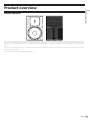
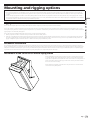
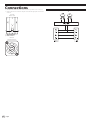
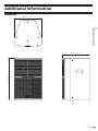
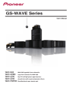
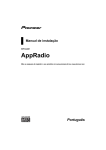
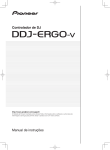
XY-152 XY Series 15 inch two way loudspeaker User’s Manual Contents Introduction Before you start........................................................................................................... 3 Installation guidelines................................................................................................ 4 Features....................................................................................................................... 4 Product overview Product overview........................................................................................................ 5 System set-up Stand mounting.......................................................................................................... 6 Ground stacking......................................................................................................... 6 Cabling and amplifier selection................................................................................. 6 Cabling........................................................................................................................ 6 Speaker protection and Processor setting................................................................ 6 Mounting and rigging options Rigging hardware and accessories........................................................................... 7 Permanent installations............................................................................................. 7 Attachment of the CP-XY15VC1 Vertical Flying Cradle............................................. 7 Attachment of the CP-XY15HC1 Horizontal Flying Cradle........................................ 8 Attachment of the CP-XY15AB1 Variable Angle Bracket.......................................... 8 Assembly of clusters using the CP-XY15DF1 Dual Enclosure Flying Plate set....... 9 Attachment of wall mount brackets.......................................................................... 9 To rotate the HF waveguide........................................................................................ 9 Connections Internal connection diagram................................................................................... 10 Additional information Dimensions............................................................................................................... 11 About trademarks and registered trademarks....................................................... 12 Specifications........................................................................................................... 12 2 Engb WARNING ! This loudspeaker must be installed by a qualified technician as it involves such tasks as selecting a location for installation, drilling holes in walls/ceiling and wiring. Have the installer carefully follow the installation instructions. ! Certain technical skills are required to install the loudspeaker. Please have the product installed by a professional. ! Pioneer is not responsible for any loss or damage that results from improper installation, insufficient strength of installation materials, misuse, modification or natural disasters. Introduction Introduction Thank you for buying this Pioneer product. Please read through these operating instructions so you will know how to operate your model properly. After you have finished reading the instructions, put them away in a safe place for future reference. Before you start ! Make sure to use amplifiers with rated load impedances that match the speaker impedance for the amplifiers connected to each loudspeaker. ! Furthermore, any devices or objects easily affected by magnetism (floppy disks, magnetic cards, magnetic tape etc.) should be kept well away from the speakers. In order to prevent damage to the loudspeaker resulting from input overload, please observe the following precautions: ! If you supply amplification power to the loudspeaker excessively, the speaker could be damaged and overheating could cause a hazard. ! Only connect, turn ON or OFF the audio system or any one part (such as DJ player and Mixer) when the power to the amplifier is turned off. If any operations are performed while the amplifier is turned on, there is the possibility of damaging the treble frequency speaker unit. ! When using a graphic equaliser to emphasise loud sounds in the high-frequency range, do not use excessive amplifier volume. ! Do not try to force a low-powered amplifier to produce high sound levels as the amplifier’s harmonic distortion will be increased, and you may damage the speaker. Caution: installation ! ! ! ! ! ! ! ! ! ! ! ! ! Ensure that the floor or stage surface can withstand the weight of the system. The installation technician must follow professional installation techniques to protect the loudspeaker against falling. When installing the speakers, make sure that the wall/ceiling is strong enough to support the speakers. Improper installation of the speakers could cause them to fall and cause damage or injuries to persons nearby. Do not attempt to stack devices together for use other than specified systems. Such devices may become unstable and tip over or fall, leading to injury. Make sure to secure each device in place using the pole mount, ratchet straps or other hardware to prevent them from tipping over or falling when stacking devices together. Pioneer shall accept no liability for damage or injury caused by accidents resulting from Pioneer products tipping over or falling due to them being insufficiently secured. Switch off and unplug your power amplifier and consult the instructions when connecting up components. Make sure you use the correct connecting cables. Keep magnetic objects such as screwdrivers or steel parts away from the tweeter and woofer speakers. Since the speakers use strong magnets, the objects may be attracted, causing injury or damaging the diaphragm. Do not install the loudspeaker in areas exposed to direct sunlight or near heating appliances. Such conditions may result in shrinkage of the wood materials and finish, leading to deformation of the enclosure, discolouration, or damage to the speakers. Conditions considered unpleasant by humans are detrimental to speakers as well. Providing a comfortable environment for the speakers will assist them in demonstrating their best performance. Please maintain the usage environment as follows: Temperature: 15 °C to 25 °C (59 °F to 77 °F) Relative Humidity: 35 % to 65 % (winter) 40 % to 70 % (summer) Do not store speakers at temperatures outside of the rated temperature range as doing so may cause the speaker to drop in performance or become damaged. Storage temperature range: –20 °C to +55 °C (–4 °F to +131 °F) Do not use the product in locations subject to extreme fluctuations in temperature. Doing so could cause the product to malfunction. When using room air-conditioners or stoves to rapidly cool or heat room spaces, take precautions to avoid excessive dehumidification. Avoid placing the speaker near areas such as windows, as outside air can cause condensation to occur within the speaker. This loudspeaker is designed for indoor use only. To avoid electric shock hazard, do not place them outside, or in an overly humid area. Caution: in use ! Do not use the speaker to output distorted sound for long periods of times. This can result in a fire hazard. ! Please also remember that vibrations from subwoofer systems can shake other loudspeakers out of place, which may present a toppling hazard. ! Do not attempt to use the product with the XY-152 grille detached as doing so could result in damage to the product. Consult a qualified professional for assistance with removing the grille for maintenance purposes. For Europe If you want to dispose of this product, do not mix it with general household waste. There is a separate collection system for used electronic products in accordance with legislation that requires proper treatment, recovery and recycling. Private households in the member states of the EU, in Switzerland and Norway may return their used electronic products free of charge to designated collection facilities or to a retailer (if you purchase a similar new one). For countries not mentioned above, please contact your local authorities for the correct method of disposal. By doing so you will ensure that your disposed product undergoes the necessary treatment, recovery and recycling and thus prevent potential negative effects on the environment and human health. K058b_A1_Engb For U.S.A. WARNING: This product contains chemicals known to the State of California and other governmental entities to cause cancer and birth defects or other reproductive harm. D36-P5_C1_En Engb 3 The Safety of Your Ears is in Your Hands Get the most out of your equipment by playing it at a safe level – a level that lets the sound come through clearly without annoying blaring or distortion and, most importantly, without affecting your sensitive hearing. Sound can be deceiving. Over time, your hearing “comfort level” adapts to higher volumes of sound, so what sounds “normal” can actually be loud and harmful to your hearing. Guard against this by setting your equipment at a safe level BEFORE your hearing adapts. ESTABLISH A SAFE LEVEL: • Set your volume control at a low setting. • Slowly increase the sound until you can hear it comfortably and clearly, without distortion. • Once you have established a comfortable sound level, set the dial and leave it there. BE SURE TO OBSERVE THE FOLLOWING GUIDELINES: • Do not turn up the volume so high that you can’t hear what’s around you. • Use caution or temporarily discontinue use in potentially hazardous situations. • Do not use headphones while operating a motorised vehicle; the use of headphones may create a traffic hazard and is illegal in many areas. S001a_A1_Engb Installation guidelines WARNING ! This loudspeaker must be installed by a qualified technician as it involves such tasks as selecting a location for installation, drilling holes in walls/ceiling and wiring. Have the installer carefully follow the installation instructions. ! Certain technical skills are required to install the loudspeaker. Please have the product installed by a professional. ! Pioneer is not responsible for any loss or damage that results from improper installation, insufficient strength of installation materials, misuse, modification or natural disasters. The XY-152 comes with pre-inserted mounting screws. These screws can be taken out and used to attach either special mounting hardware designed for the product or commercially available mounting hardware. Make sure to attach a wire for preventing falling parts and equipment of adequate strength using screw holes not used by mounting hardware. WARNING ! When attaching the speakers to the wall or ceiling, you should first confirm that the wall or ceiling being used is strong enough to support their weight. If you are unsure then consult a specialist. If the speakers should fall then it could lead to serious injury, and is potentially very dangerous. ! Check to make sure that any mounting hardware used is enough to support the system, whether using special hardware designed for the system or commercially available hardware. Make sure to read the Introduction section in this manual and the instruction manual for the mounting hardware thoroughly before proceeding. Take every precaution to prevent the product and associated parts from falling as they could cause serious injury if they fell onto a person. ! Use screws suitable for ceiling material and screw mounting parts in solid locations. ! After installation, you must confirm that the speakers are safely installed. You must also periodically check them to make sure that they are still safe. ! Make sure to use mounting hardware of sufficient strength to secure the speaker in place when using non-designated hardware. The speaker could fall, causing accidents, if not properly secured. ! The fall prevention wire must be attached to a suitably strong location. The strength of the location to which the wire is attached being insufficient can lead to the speakers falling or cause accidents. The fall prevention wire and screw to attach the fall prevention wire to the ceiling or wall are not supplied with the speakers, so please purchase them separately. ! When this product is placed in an elevated place such as on a shelf, a speaker may be moved by vibrations and fall to the floor, causing an injury or accident. Take measures to prevent a speaker from sliding off a shelf, etc. ! Ensure that the floor or stage surface can withstand the weight of the system. ! Wherever possible, avoid high stacks and use ratchet straps to secure loudspeakers together. Please also remember that vibrations from subwoofer systems can shake other loudspeakers out of place, which may present a toppling hazard. The use of ratchet straps and non-slip material is recommended to prevent this. Features ! ! ! ! ! ! ! ! 4 Two-way full range speaker with 15 inch LF driver and a 1.4 inch compression driver. Passive crossover board features separate cooling zones to ensure safe and continuous operations in the toughest environments. Wide dispersion of 90 × 60 degrees, with rotatable horn for horizontal installation. Designed for fixed and mobile applications, with a wide array of flying options. Features top hats for quick set-up. NL4 INPUT and LINK OUT connections as standard. Robust enclosure made from premium multi-laminate birch plywood. Impact resistant textured paint finish. Engb Product overview Product overview Product overview The XY-152 is a very high-output, versatile, passive loudspeaker product designed for a wide variety professional sound reinforcement applications. It features a high-power 15 inch (380 mm) neodymium LF drive unit in a reflex enclosure, and a 3 inch (75 mm) diaphragm, 1.4 inch (36 mm) exit neodymium high frequency compression drive unit coupled to a 90 ° × 60 ° rotatable waveguide. These components are matched by an internal passive crossover network for unprecedented sonic quality from a completely passive enclosure. Due to its discreet size and appearance, the XY-152 can be used in a wide variety of applications ranging from fills and delays in nightclub use to medium scale front of house and DJ booth monitoring duty. The XY-152 is fitted with two Neutrik SpeakON™ NL4 connectors. Engb 5 System set-up WARNING ! Loudspeaker systems are potentially dangerous objects if used incorrectly. Please ensure that you read this section fully, and contact your local dealer should you be in any doubt over correct operation procedures. ! Professional loudspeaker systems are capable of producing damage-inducing sound pressure levels, and hence care should be taken when setting your system up, particularly when it comes to loudspeaker placement within a venue. Damage to the ear can result from levels above 90 dB under prolonged exposure. Stand mounting The XY-152 can be mounted from a loudspeaker stand using the integral polemount adapter for a standard 35 mm (1.4 in.) loudspeaker stand. When mounting in this way, please consider the following: ! Ensure your stand height is locked off and the tripod legs are positioned so as to be stable. ! Check the weight loading of your stands before attempting to mount the loudspeaker. ! Do not stack a second loudspeaker on top of the stand-mounted one. ! Ensure cables are run so as to leave enough slack to enable neat wiring, and thus reduce the risk of the speaker being pulled over. Loose cables should be covered or taped down wherever possible to reduce trip hazards. ! When using poles on top of subwoofer systems, please observe similar precautions. Ground stacking ! Ensure that the floor or stage surface can withstand the weight of the system. ! Wherever possible, avoid high stacks and use ratchet straps to secure loudspeakers together. Please also remember that vibrations from subwoofer systems can shake other loudspeakers out of place, which may present a toppling hazard. The use of ratchet straps and non-slip material is recommended to prevent this. Cabling and amplifier selection The XY-152 is designed to be used with professional power amplifiers providing the following power outputs: ! 1300 W/channel into 8 W NOTE A small power amplifier working too hard is more likely to damage a loudspeaker than a large power amplifier working within its operating range. It is good practice to use an amplifier equal to the program power rating of the loudspeaker — so as to retain sufficient headroom and good dynamic range. Care should be taken during operation to avoid amplifier clipping — as this can cause serious damage to your loudspeakers. If in doubt, please contact your dealer who will be happy to assist you in correct amplifier choice and setup. Cabling The XY-152 is supplied as standard with Neutrik SpeakON™ NL4 connectors, wired pin 1+/1–. It is recommended that the resistance of your cable be less than one tenth of the nominal system impedance. Given below are the recommended maximum cable lengths for different cross-sections and impedances. Conductor cross sectional area Maximum recommended cable length 4W 8W 16 W 1.0 mm2 11 m 22 m 44 m 1.5 mm2 17 m 34 m 68 m 2.0 mm2 22 m 44 m 88 m 2.5 mm2 29 m 58 m 116 m 4.0 mm2 44 m 88 m 176 m 6.0 mm2 66 m 132 m 264 m ! Pins 2+/2– on the Neutrik SpeakON™ connectors are wired together to allow link-through with 4-core cables. Speaker protection and Processor setting WARNING The XY-152 requires no DSP program to function correctly. However, excessive low frequency information will cause the LF drive unit’s excursion to increase, which can result in damage to your loudspeaker. It is recommended to appropriately set the values of crossover frequency and peak limiter on the amplifier for loudspeaker protection. Please refer to the PDF file in the “Installation Manual” and “Processor Settings” of the following webpage for the recommended values of crossover frequency and peak limiter to appropriately use this product. http://pioneerproaudio.com/ja/resources.html 6 Engb Mounting and rigging options WARNING Rigging hardware and accessories The XY-152 has multiple options for mounting and suspension, both for temporary use and for permanent, fixed installation. The XY-152 contains 15 of M10 threaded fixing points around the enclosure, to enable suspension using forged shoulder eyebolts (minimum thread length: 30 mm (1.2 in.)) or the optional flying hardware. These fixings allow suspension in any orientation, with the extra point on the rear of the enclosure available for pull-back to obtain the desired rigging angle or as a secondary safety point. The XY-152 also has four M8 threaded fixings on the rear for use with wall mount brackets. ! With any suspension method, a second anchor point should be used as a safety feature. ! Under no circumstances should the mounting points of one enclosure be used to suspend another enclosure below it. Pioneer is in no way responsible for the failure of incorrectly rigged systems. This information relates specifically to the rigging techniques for the XY-152 enclosure only. If you are in any doubt about safe practices for rigging loudspeakers, please contact the retailer or dealer from which you purchased this product. Mounting and rigging options ! The overhead suspension of loudspeakers is a very serious issue with potentially lethal consequences should anything go wrong. Rigging should only be carried out by experienced personnel following safe working practice. Should you be in any doubt whatsoever, please contact the retailer or dealer from which you purchased this product. ! When utilising any suspension method, a secondary safety feature must be used. For any suspension method, fit an M10 eyebolt to any of the rigging points. A safety steel can then be attached to this and connected to your safety point. If you are in any doubt whatsoever about how to safely suspend your loudspeakers, do not hesitate to contact the retailer or dealer from which you purchased this product. Permanent installations Any installation (permanent or temporary) must be securely attached to the structure of the building using chain, steel wire or web straps that are certified and load rated for the loudspeaker system. Consideration must be taken when determining the loading on the structure to include loudspeakers and rigging hardware, and the appropriate safety factor can then be decided upon. If you are in any doubt whatsoever, please contact the retailer or dealer from which you purchased this product. A reputable rigging organisation should also be able to advise on legislation regarding safety factors for suspended systems of this type. Attachment of the CP-XY15VC1 Vertical Flying Cradle Ensure that both the flat and locking washers are used – the flat washer should be in contact with the cradle. Tighten the bolts to ensure a solid fit. Once the desired angle of the loudspeaker is set, tighten the levers on the cradle to lock the position in place. The points on the top of the flying cradle can be used for permanent installations or to secure a hook clamp. Ensure that an M10 eyebolt is secured to the rear point on the XY-152 enclosure to use as a secondary safety feature. Engb 7 Attachment of the CP-XY15HC1 Horizontal Flying Cradle Using the supplied M10 socket head bolts, align the mounting holes in the end mounts of the yoke with the mounting points on the top and the bottom of the enclosure. Ensure that both the flat and locking washers are used — the flat washer should be in contact with the cradle. Tighten the bolts to ensure a solid fit. Once the desired angle of the loudspeaker is set, tighten the levers on the cradle to lock the position in place. The points on the top of the flying cradle can be used for permanent installations or to secure a hook clamp. Ensure that an M10 eyebolt is secured to the rear point on the XY-152 enclosure to use as a secondary safety feature. Attachment of the CP-XY15AB1 Variable Angle Bracket Using the supplied M10 hex head bolts, align the mounting holes in the flying bracket with the mounting points on the top or the bottom of the enclosure. Ensure that both the flat and locking washers are used — the flat washer should be in contact with the cradle. Tighten the bolts to ensure a solid fit. Finally, attach a hookclamp to the mounting point. The flying bracket works on the centre of gravity of the XY-152. Moving the pickup point to the rear of the enclosure will add down-tilt, and moving to the front of the enclosure will apply up-tilt. For larger down-tilt angles, position the pivot on the last hole and use the point on the rear or underside as a pull-back. Ensure that an M10 eyebolt is secured to the top point on the XY-152 enclosure to use as a secondary safety feature. 8 Engb Assembly of clusters using the CP-XY15DF1 Dual Enclosure Flying Plate set Using the supplied M10 socket head bolts, bolt through the CP-XY15DF1 plate into the enclosures. Ensure that both the flat and spring washers are used — the flat washer should be in contact with the plate. Once the desired angles of the loudspeakers are set, tighten the bolts to lock in place. Then turn the cluster over and repeat the process on the bottom. Use the top points on the XY-152 enclosures as a secondary safety feature. Mounting and rigging options Attachment of wall mount brackets ! Four holes (M8) for wall mount brackets are provided on the rear of the XY-152. ! Hole layout (pitch): 127 mm × 70 mm (5 in. × 2.8 in.) ! Be sure to use wall mount brackets that have enough strength to be able to withstand the weight of the XY-152. To rotate the HF waveguide 1 2 3 4 5 Using a 4 mm Allen key, unscrew the six M6 screws in the top and bottom of the enclosure (3 at each end). Gently remove the grille from the front of the enclosure. Using a 4 mm Allen key, remove the eight countersunk bolts holding the HF waveguide in place. Lift the waveguide up and rotate to the desired position. Reinstate the socket-head bolts and retighten. Avoid over-tightening as this may crack the waveguide. Reinstate the grille by gently placing it in place over the front of the loudspeaker. Replace the six M6 screws to secure it in place. Engb 9 Connections ! The INPUT and LINK connectors used are Neutrik SpeakON™ NL4 connectors. ! Refer to the internal connection diagram and make the appropriate connections as shown. XY-152 Rear view 1 2 1 INPUT connector 2 LINK connector Neutrik NL4 Connector 10 Engb Internal connection diagram Additional information Dimensions 440 mm (17.3 in.) Additional information 715 mm (28.1 in.) 444 mm (17.5 in.) Engb 11 About trademarks and registered trademarks ! Pioneer is a registered trademark of PIONEER CORPORATION. ! SpeakON is a registered trademark of Neutrik. The names of companies and products mentioned herein are the trademarks of their respective owners. Specifications Enclosure Type Two-way passive, reflex-loaded Frequency Response 50 Hz to 20 kHz Sensitivity (1 W/1 m) 98 dB Nominal Impedance 8 W Power Handling 650 W RMS, 1300 W Program Maximum SPL 126 dB cont., 132 dB peak Dispersion 90 °H × 60 °V, Rotatable Driver Configuration 15 inch (380 mm) neodymium LF cone driver, 1.4 inch (36 mm) exit neodymium HF compression driver Crossover Asymmetric internal passive crossover Connectors 2 × Neutrik SpeakON™ NL4 Dimensions (W×H×D) 440 mm × 715 mm × 444 mm (17.3 inch × 28.1 inch × 17.5 inch) Weight 29 kg (63.9 lb) Rigging and Hardware 8 × M10 threaded mounting points (4 top/4 bottom), 3 × M10 threaded mounting points on rear, 4 × M10 threaded mounting points on side (2 left/2 right), 4 × M8 threaded points on rear (for wall mount bracket), 2 × flush handles (1 left/1 right), 1 × 35 mm polemount socket Grille Hex punched steel Enclosure 15 mm (0.6 inch) birch plywood Finish Impact-resistant, Black semi-matt textured The specifications and design of this product are subject to change without notice. 12 Engb © 2014 PIONEER CORPORATION. All rights reserved. PIONEER CORPORATION 1-1, Shin-ogura, Saiwai-ku, Kawasaki-shi, Kanagawa 212-0031, Japan 〒 212-0031 神奈川県川崎市幸区新小倉1番1号 Корпорация Пайонир 1-1, Син-Огура, Сайвай-ку, г. Кавасаки, префектура Канагава, 212-0031, Япония Импортер: ООО "ПИОНЕР РУС" 125040, Россия, г. Москва, ул. Правды, д.26 Тел.: +7(495) 956-89-01 PIONEER EUROPE NV Haven 1087, Keetberglaan 1, B-9120 Melsele, Belgium TEL: 03/570.05.11 PIONEER ELECTRONICS (USA) INC. P.O. BOX 1720, Long Beach, California 90801-1720, U.S.A. TEL: (800) 421-1404 PIONEER ELECTRONICS ASIACENTRE PTE. LTD. 253 Alexandra Road, #04-01, Singapore 159936 TEL: 65-6472-7555 PIONEER ELECTRONICS AUSTRALIA PTY. LTD. 5 Arco Lane, Heatherton, Victoria, 3202, Australia, TEL: (03) 9586-6300 PIONEER ELECTRONICS (THAILAND) CO., LTD. 17th Fl., KPN Tower, 719 Rama 9 Road, Bangkapi, Huaykwang, Bangkok 10310 TEL: 66-2-717-0777 PIONEER TECHNOLOGY (MALAYSIA) SDN. BHD 16th Floor, Menara Uni. Asia 1008 Jalan Sultan Ismail 50250 Kuala Lumpur TEL: 60-3-2697-2920 ӒᎣӌԥ४ϵѨ ѯᢋѯіҀϲୣ࿆ӏ ĵıĸ ဵ Ĺ ዃ TEL: 886-(0)2-2657-3588 ӒᎣႬφȞॸ෬ȟԥ४ϵѨ ॸ෬Οᓹߞؔᢋၿ ĺıĺġဵ Ķġዃ TEL: 852-2848-6488 PIONEER GULF FZE Lob 11-017, Jebel Ali Free Zone P.O. Box 61226, Jebel Ali Dubai TEL: 971-4-8815756 PIONEER ELECTRONICS DE MEXICO S.A. DE C.V. Blvd.Manuel Avila Camacho 138 10 piso Col.Lomas de Chapultepec, Mexico, D.F. 11000 TEL: 55-9178-4270 PIONEER INTERNATIONAL LATIN AMERICA S.A. Plaza Credicorp Bank, 14th Floor, Calle 50, No.120 Panama City 0816-01361 Republic of Panama TEL: 507-300-3900 PIONEER KOREA CORPORATION (PKC) ㎶⠞⛎፲◮⿾ᩖ◮+⦦,#4540353#⇆❢㍣ᵮ⎆#ᩲ㒖ถ#ඟᒃ#438054<#⢿㛾Ỷᗓ###TEL: 02-777-8005 <DRB1729-A>