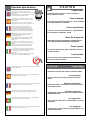
1
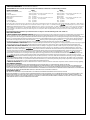
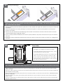
PA 4 0 L O W E R I N G A R M
Service Camera at Ease from 75 feet
www.videolarm.com
Installation and Operation Instructions for the following models:
PA40
Lowering arm mount, easily and safely lowers camera down from up to 75 ft for servicing. Includes electronically controlled winch
PA40D
Lowering arm with surge and video protection
Dome / Camera System not included (Sold Separately)
Before attempting to connect or operate this product,
please read these instructions completely.
CERTIFIED
81-IN5430
05-06-2010
IMPORTANT SAFEGUARDS
1
Read these instructions.
2
Keep these instructions.
3
Heed all warnings
4
Follow all instructions.
5
Do not use this apparatus near water.
6
Clean only with damp cloth.
7
SAFETY PRECAUTIONS
CAUTION
RISK OF ELECTRIC SHOCK
DO NOT OPEN
CAUTION: TO REDUCE THE RISK OF
ELECTRIC SHOCK, DO NOT REMOVE
COVER ( OR BACK). NO USER- SERVICEABLE PARTS INSIDE. REFER SEVICING
TO QUALIFIED SERVICE PERSONNEL.
Do not block any of the ventilation openings. Install in accordance with the
manufacturers instructions.
8
9
Cable Runs- All cable runs must be within permissible distance.
Mounting - This unit must be properly and securely mounted to a supporting
structure capable of sustaining the weight of the unit.
Accordingly:
a. The installation should be made by a qualified installer.
b. The installation should be in compliance with local codes.
c. Care should be exercised to select suitable hardware to install the unit, taking into
account both the composition of the mounting surface and the weight of the unit.
10 Do not install near any heat sources such as radiators, heat registers, stoves, or other
apparatus ( including amplifiers) that produce heat.
11 Do not defeat the safety purpose of the polarized or grounding-type plug. A
polarized plug has two blades with one wider than the other. A grounding type
plug has two blades and a third grounding prong. The wide blade or the third
prong are provided for your safety. When the provided plug does not fit into your
outlet, consult an electrician for replacement of the obsolete outlet.
12 Protect the power cord from being walked on or pinched particularly
at plugs,
convenience receptacles, and the point where they exit from the apparatus.
13 Only use attachment/ accessories specified by the manufacturer.
14 Use only with a cart, stand, tripod, bracket, or table specified by the manufacturer,
or sold with the apparatus. When a cart is used, use caution when moving the cart/
apparatus combination to avoid injury from tip-over.
15 Unplug this apparatus during lighting storms or when unused for long periods of time.
16 Refer all servicing to qualified service personnel. Servicing is required when the
apparatus has been damaged in any way, such as power-supply cord or plug is
damaged, liquid has been spilled of objects have fallen into the apparatus, the
The lightning flash with an arrowhead symbol,
within an equilateral triangle, is intended to
alert the user to the presence of non-insulated
“dangerous voltage” within the product’s
enclosure that may be of sufficient magnitude
to constitute a risk to persons.
Este símbolo se piensa para alertar al usuario a la presencia
del “voltaje peligroso no-aisIado” dentro del recinto de los
productos que puede ser un riesgo de choque eléctrico.
Ce symbole est prévu pour alerter I’utilisateur à la presence
“de la tension dangereuse” non-isolée dans la clôture de
produits qui peut être un risque de choc électrique.
Dieses Symbol soll den Benutzer zum Vorhandensein der
nicht-lsolier “Gefährdungsspannung” innerhalb der
Produkteinschließung alarmieren die eine Gefahr des
elektrischen Schlages sein kann.
Este símbolo é pretendido alertar o usuário à presença “di
tensão perigosa non-isolada” dentro do cerco dos produtos
que pode ser um risco de choque elétrico.
Questo simbolo è inteso per avvertire I’utente alla presenza
“di tensione pericolosa” non-isolata all’interno della
recinzione dei prodotti che può essere un rischio di scossa
elettrica.
apparatus has been exposed to rain or moisture, does not operate normally, or
has been dropped.
Be sure to periodically examine the unit and the supporting structure to make sure that the integrity
of the installation is intact. Failure to comply with the foregoing could result in the unit separating
from the support structure and falling, with resultant damages or injury to anyone or anything struck
by the falling unit.
UNPACKING
Unpack carefully. Electronic components can be
damaged if improperly handled or dropped. If an item
appears to have been damaged in shipment, replace
it properly in its carton and notify the shipper.
Be sure to save:
1 The shipping carton and packaging material.
They are the safest material in which to make future
shipments of the equipment.
2 These Installation and Operating Instructions.
SERVICE
If technical support or service is needed, contact us at
the following number:
TECHNICAL SUPPORT
AVAILABLE 24 HOURS
1- 800 - 554 -1124
The exclamation point within an equilateral
triangle is intended to alert the user to
presence of important operating and
maintenance (servicing) instructions in the
literature accompanying the appliance.
Este símbolo del punto del exclamation se piensa para
alertar al usuario a la presencia de instrucciones importantes
en la literatura que acompaña la aplicación.
Ce symbole de point d’exclamation est prévu pour alerter
l’utilisateur à la presence des instructions importantes dans
la littérature accompagnant l’appareil.
Dieses Ausruf Punktsymbol soll den Benutzer zum
Vorhandensein de wichtigen Anweisungen in der Literatur
alarmieren, die das Gerät begleitet.
Este símbolo do ponto do exclamation é pretendido alertar o
usuário à presença de instruções importantes na literatura
que acompanha o dispositivo.
Questo simbolo del punto del exclamaton è inteso per
avvertire l’utente alla presenza delle istruzioni importanti nella
letteratura che accompagna l'apparecchio.
LIMITED WARRANTY FOR VIDEOLARM INC. PRODUCTS
VIDEOLARM INC. warrants this Product to be free from defects in material or workmanship,as follows:
PRODUCTCATEGORY
PARTS
LABOR
All Enclosuresand Electronics
Five (5) Years
Five (5) Years
Pan/Tilts
Three (3) Years **6 months if used in autoscan
Three (3) Years **6 months if used in autoscan
/tour operation
Poles/PoleEvators
Three (3) Years /tour operation
Three (3) Years
Warrior/Q-View/I.R.Illuminators
Five (5) Years
Five (5) Years
Five (5) Years **6 months if used in autoscan
SView Series
Five (5) Years **6 months if used in autoscan
/tour operation
Controllers
Five (5) Years /tour operation
Five (5) Years
PowerSupplies
Five (5) Years
Five (5) Years
AccessoryBrackets
Five (5) Years
Five (5) Years
During the labor warranty period, to repair the Product,Purchaserwill either return the defective product, freight prepaid, or deliver it to Videolarm Inc.
an equal degree of protection with a
Decatur GA.The Productto be repaired is to be returned in either its original carton or a similar package
RMA# (Return Materials Authorization number) displayed on the outer box or packing slip. To obtain a RMA#you must contact our TechnicalSupport
Team at 800.554.1124,extension 101.Videolarm will return the repaired Productfreight prepaid to Purchaser.Videolarm is not obligated to provide
Purchaserwith a substitute unit during the warranty period or at any time. After the applicable warranty period, Purchasermust pay all labor and/or
parts charges.
The limited warranty stated in these product instructions is subject to all of the following terms and conditions:
TERMS AND CONDITIONS
1. NOTIFICATIONOF CLAIMS: WARRANTYSERVICE: If Purchaser believes that the Product is defective in material or workmanship, then written notice
with an explanation of the claim shall be given promptly by Purchaser to Videolarm but all claims for warranty service must be made within the
warranty period. If after investigation Videolarm determines that the reported problem was not covered by the warranty, Purchaser shall pay Videolarm
for the cost of investigating the problem at its then prevailing per incident billable rate. No repair or replacement of any Product or part thereof shall
extend the warranty period as to the entire Product. The
warranty on the repaired part only shall be in
for a period of ninety (90) days
following the repair or replacement of that part or the remaining period of the Product parts warranty, whichever is greater.
2. EXCLUSIVE REMEDY: ACCEPTANCE:Purchaser’s exclusive remedy and Videolarm’s sole obligation is to supply (or pay for) all labor necessary to repair
any Product found to be defective within the warranty period and to supply, at no extra charge, new or rebuilt replacements for defective parts.
3. EXCEPTIONS TO LIMITED WARRANTY: Videolarm shall have no liability or obligation to Purchaser with respect to any Product requiring service
during the warranty period which is subjected to any of the following: abuse, improper use: negligence, accident, lightning damage or other acts
of God (i.e., hurricanes, earthquakes),
failure of the end-user to follow the directions outlined in the product instructions, failure of the
end-user to follow the maintenance procedures recommended by the International Security Industry Organization, written in product instructions,
for regular
or recommended in the service manual for the Product. Furthermore, Videolarm shall have no liability where a schedule is
replacement or maintenance or cleaning of certain parts (based on usage) and the end-user has failed to follow such schedule; attempted repair by
personnel; operation of the Product outside of the published environmental and electrical parameters, or if such Product’s original
(trademark, serial number) markings have been defaced, altered, or removed. Videolarm excludes from warranty coverage Products sold
AS IS and/or WITH ALL FAULTS and excludes used Products which have not been sold by Videolarm to the Purchaser. All software and accompanying
documentation furnished with, or as part of the Product is furnished “AS IS” (i.e., without any warranty of any kind), except where expressly provided
otherwise in any documentation or license agreement furnished with the Product.
4. PROOF OF PURCHASE: The Purchaser’s dated bill of sale must be retained as evidence of the date of purchase and to establish warranty eligibility.
DISCLAIMEROF WARRANTY
EXCEPT FOR THE FOREGOING WARRANTIES, VIDEOLARM HEREBY DISCLAIMS AND EXCLUDES ALL OTHER WARRANTIES, EXPRESS OR IMPLIED,
INCLUDING, BUT NOT LIMITED TO ANY AND/OR ALL IMPLIED WARRANTIES OF MERCHANTABILITY, FITNESS FOR A PARTICULAR PURPOSE AND/OR ANY WARRANTY WITH
REGARD TO ANY CLAIM OF INFRINGEMENT THAT MAY BE PROVIDED IN SECTION 2-312(3) OF THE UNIFORM COMMERCIAL CODE AND/OR IN ANY OTHER COMPARABLE
STATE STATUTE. VIDEOLARM HEREBY DISCLAIMS ANY REPRESENTATIONS OR WARRANTY THAT THE PRODUCT IS COMPATIBLE WITH ANY COMBINATION OF NON-VIDEOLARM
PRODUCTS OR NON-VIDEOLARM RECOMMENDED PRODUCTS PURCHASER CHOOSES TO CONNECT TO PRODUCT.
LIMITATION OF LIABILITY
THE LIABILITY OF VIDEOLARM, IF ANY, AND PURCHASER’S SOLE AND EXCLUSIVE REMEDY FOR DAMAGES FOR ANY CLAIM OF ANY KIND
WHATSOEVER, REGARDLESS OF THE LEGAL THEORY AND WHETHER ARISING IN TORT OR CONTRACT, SHALL NOT BE GREATER THAN THE ACTUAL PURCHASE PRICE OF THE
PRODUCT WITH RESPECT TO WHICH SUCH CLAIM IS MADE. IN NO EVENT SHALL VIDEOLARM BE LIABLE TO PURCHASER FOR ANY SPECIAL, INDIRECT, INCIDENTAL, OR
CONSEQUENTIAL DAMAGES OF ANY KIND INCLUDING, BUT NOT LIMITED TO, COMPENSATION, REIMBURSEMENT OR DAMAGES ON ACCOUNT OF THE LOSS OF PRESENT
OR PROSPECTIVE PROFITS OR FOR ANY OTHER REASON WHATSOEVER.
!
English
Electrical & Mechanical Specifications
PA40 Lowering Arm
Power 120 VAC
10 A Max
Maximum weight limit of 35 lbs (15.9kg) may be
attached to lowering device.
PA40 may be lowered to a maximum safe operating
distance of 75 feet (22.9 m).
Tools Required: Flat Head Screwdriver
Ceiling Support Wires(.14 - 10 )
Español
Energía 120 VAC
10 A Max
El límite del peso máximo de 35 libras (15.9kg) se puede
atar a bajar el dispositivo.
PA40 se puede bajar a una distancia segura máxima
del funcionamiento de 75 pies (22.9 m).
Herramientas Requeridas: Destornillador Principal Flat
Alambre De la Galga De la Ayuda Wires(.14 - 10 )
Français
Puissance 120 VAC
10 A Max
La limite de poids maximum de 35 livres (15.9kg) peut
être attachée à abaisser le dispositif.
PA40 peut être abaissé à une distance sûre maximum
d'opération de 75 pieds (22.9 m).
Outils Requis : Tournevis Principal Flat
Fil De Mesure De Soutien Wires(.14 - 10 )
Deutsch
Energie 120 VAC
10 A Max
Höchstgewichtbegrenzung auf 35 lbs (15.9kg) kann zur
Senkung der Vorrichtung angebracht werden.
PA40 kann zu einem maximalen sicheren
Betriebsabstand von 75 Fuß (22.9 m) gesenkt werden.
Werkzeuge Erfordert: Flacher Hauptschraubenzieher
Decke Unterstützungswires (.14 - 10 )
Portuguese
Poder 120 VAC
10 A Max
O limite do peso máximo de 35 libras (15.9kg) pode ser
unido a abaixar o dispositivo.
PA40 pode ser abaixado a uma distância segura
máxima do funcionamento de 75 pés (22.9 m).
Ferramentas Requeridas: Chave de fenda Principal Flat
Fio Do Calibre Da Sustentação Wires(.14 - 10 )
Italiano
Alimentazione 120 VAC
10 A Max
Un limite del peso massimo di 35 libbre (15.9kg) può
essere attaccato ad abbassare il dispositivo.
PA40 può essere abbassato ad una distanza sicura
massima di funzionamento di 75 piedi (22.9 m).
Gli Attrezzi Hanno richiesto: Cacciavite Capo "Flat"
Legare Del Calibro Di Sostegno Wires(.14 - 10 )
Contents of Box
!
English
!
Operation Specifications
Video transmission is available only when lowering
mechanism (camera enclosure) has been docked in lowering
arm apparatus.
After two continuous cycles (Up/Down,STEP
Up/Down)
allow PA40
6:
USE A STANDARD LEVEL TO ENSURE THE
to cool-down for 20 minutes before operating.
HORIZONTAL ALINGMENT OF THE UNIT.
Español
Français
Deutsch
Portuguese
Italiano
La transmission visuelle est disponible seulement en
abaissant le mécanisme (clôture d'appareil-photo) a été
accouplée dans un appareillage de bras d'abaissement.
Après deux cycles continus (haut/bas, haut/bas), permettez
PA40 frais-vers le bas pendant 20 minutes avant l'opération.
Bildübertragung ist vorhanden, nur wenn sie Mechanismus
(Kameraeinschließung) ist angekoppelt worden im
Senkungarmapparat senkt.
Nach zwei ununterbrochenen Zyklen (Auf-/Ab--, Auf-/Ab),
erlauben Sie PA40, das für 20 Minuten kühlist, bevor Sie
funktionieren.
A transmissão video está disponível somente ao abaixar o
mecanismo (cerco da câmera) foi entrada no instrumento do
antebraço.
Após dois ciclos contínuos (Up/Down, Up/Down), permita
PA40 fresco-para baixo por 20 minutos antes de operar.
La video trasmissione è disponibile soltanto quando abbassa
il meccanismo (recinzione della macchina fotografica) è stata
messa in bacino in apparecchiatura del braccio di
abbassamento.
Dopo due cicli continui (Up/Down, Up/Down), permetta PA40
freddo-giù per 20 minuti prima del funzionamento.
Cease Power
- IF THE PA40’S MOTOR STALLS, DO NOT CONTINUE TO
APPLY POWER TO THE UNIT.
IF NECESSARY, PLACE WASHERS OR SHIMS
BETWEEN LOWERING UNIT AND ADAPTER BRACKET.
La transmisión video está disponible solamente al bajar el
mecanismo (recinto de la cámara) se ha atracado en aparato
del brazo de baja.
Después de dos ciclos continuos (Up/Down, Up/Down),
permita PA40 fresco-abajo por 20 minutos antes de funcionar.
CAUTION
Cese la energía
- SI EL PA40' LAS PARADAS DEL MOTOR DE S, NO CONTINÚAN
APLICANDO ENERGÍA A LA UNIDAD.
Cessez la puissance
- SI LE PA40' ; LES STALLES DE MOTEUR DE S, NE CONTINUENT
PAS À METTRE SOUS TENSION À L'UNITÉ.
Hören Sie Energie auf
- WENN DER PA40 MOTOR FESTKLEMMT, FAHREN SIE NICHT
FORT, ENERGIE AN DER MASSEINHEIT ANZUWENDEN.
Cesse o poder
- SE O MOTOR DE PA40 PARA, NÃO CONTINUE A APLICAR O
PODER À UNIDADE.
Cessi il potere
- SE IL MOTORE DI PA40 SI ARRESTA, NON CONTINUI AD
APPLICARE IL POTERE ALL'UNITÀ.
To prevent damage and/or personal injury, do not operate PA40 device in wind
gusts of 20 mph or higher.
CAUTION
- NEVER USE YOUR PA40 FOR LIFTING OR MOVING PEOPLE.
English
Para evitar daño y/o daños corporales, no funcione el dispositivo PA40 en las
ráfagas de viento de 20 mph o más arriba.
Uso apropiado
- NUNCA UTILICE SU PA40 PARA LEVANTAR O LA GENTE
MÓVIL.
Español
Pour empêcher des dommages et/ou le dommage corporel, n'actionnez pas le
dispositif PA40 en rafales de vent de 20 M/H ou plus haut.
Français
Um Schaden und/oder Personenschaden zu verhindern, betreiben Sie
Vorrichtung nicht PA40 in den Windboen von 20 MPH oder höher.
Deutsch
Para impedir dano e/ou ferimento pessoal, não opere o dispositivo PA40 em
ventanias de vento de 20 mph ou mais altamente.
Utilisation appropriée
- N'EMPLOYEZ JAMAIS VOTRE PA40 POUR LE LEVAGE OU LES
PERSONNES MOBILES.
Korrekter Verbrauch
- VERWENDEN SIE NIE IHR PA40 FÜR DAS ANHEBEN ODER DIE
BEWEGLICHEN LEUTE.
Per evitare il danno e/o la lesione personale, non faccia funzionare il dispositivo
PA40 in raffiche di vento di 20 mph o più su.
Uso apropriado
-
NUNCA USE SEU PA40 PARA O LEVANTAMENTO OU POVOS
MOVENTES.
-
NON USI MAI IL VOSTRO PA40 PER IL SOLLEVAMENTO O LA
GENTE COMMOVENTE.
Portuguese
Italiano
Proper Usage
Uso adeguato
CAUTION
Clean Operating Area
- KEEP OPERATING AREA CLEAN. DO NOT ALLOW PEOPLE TO REMAIN
IN THE AREA DURING LOWERING/ RAISING OPERATIONS. ALWAYS
STAND CLEAR OF WIRE ROPE, PA40 MAIN UNIT AND JUNCTION BOX.
IN THE UNLIKELY EVENT OF ANY COMPONENT FAILURE IT IS BEST TO BE
OUT OF HARM’S WAY.
Limpie el área de funcionamiento
- MANTENGA EL ÁREA DE FUNCIONAMIENTO LIMPIA. NO PERMITA QUE
LA GENTE PERMANEZCA EN EL ÁREA DURANTE LA BAJA DE
OPERACIONES DE AUMENTO. COLOQÚESE SIEMPRE CLARO DE
CUERDA DE ALAMBRE, DE LA UNIDAD PRINCIPAL PA40 Y DE LA CAJA
DE ENSAMBLADURA. EN EL ACONTECIMIENTO INVEROSÍMIL DE
CUALQUIER FALTA COMPONENTE ES EL MEJOR ESTAR FUERA DE LA
MANERA DEL DAÑO.
CAUTION
Heavy Gloves
- USE HEAVY LEATHER GLOVES WHEN HANDLING WIRE ROPE. DO NOT
LET WIRE ROPE SLIDE THROUGH YOUR HANDS EVEN WHEN WEARING
GLOVES.
Guantes pesados
- UTILICE LOS GUANTES DE CUERO PESADOS AL MANEJAR LA CUERDA
DE ALAMBRE. NO DEJE LA CUERDA DE ALAMBRE RESBALAR A TRAVÉS
DE SUS MANOS INCLUSO CUANDO USA GUANTES.
Gants lourds
- EMPLOYEZ LES GANTS EN CUIR LOURDS EN MANIPULANT LE CÂBLE
MÉTALLIQUE. NE LAISSEZ PAS LE CÂBLE MÉTALLIQUE GLISSER PAR VOS
MAINS MÊME LORSQUE PORTANT DES GANTS.
Schwere Handschuhe
Nettoyez la région d'opération
- MAINTENEZ LE SECTEUR D'OPÉRATION PROPRE. NE PERMETTEZ PAS
AUX PERSONNES DE RESTER DANS LE SECTEUR PENDANT
L'ABAISSEMENT DES OPÉRATIONS AUGMENTANTES. TENEZ-VOUS
TOUJOURS DÉGAGÉ DU CÂBLE MÉTALLIQUE, DE L'UNITÉ PA40
PRINCIPALE ET DE LA BOÎTE DE JONCTION. DANS L'ÉVÉNEMENT PEU
PROBABLE DE N'IMPORTE QUEL ÉCHEC COMPOSANT IL EST LE MEILLEUR
D'ÊTRE HORS DE LA MANIÈRE DU MAL.
Säubern Sie Bedienungsfläche
- HALTEN SIE BEDIENUNGSFLÄCHE SAUBER. ERLAUBEN SIE NICHT
LEUTEN, IM BEREICH WÄHREND DER SENKUNG DER ANHEBENDEN
BETRIEBE ZU BLEIBEN. STEHEN SIE IMMER VOM DRAHTSEIL, VOM
HAUPTGERÄT PA40 UND VOM ANSCHLUSSKASTEN FREI. IM
UNWAHRSCHEINLICHEN EREIGNIS JEDES TEILausfalls ZU SEIN IST AM
BESTEN, AUS WEISE DES SCHADENS HERAUS.
- BENUTZEN SIE SCHWERE LEDERNE HANDSCHUHE, WENN SIE DRAHTSEIL
BEHANDELN. LASSEN SIE DRAHTSEIL NICHT DURCH IHRE HÄNDE
SCHIEBEN, SELBST WENN, HANDSCHUHE TRAGEND.
Luvas pesadas
- USE LUVAS DE COURO PESADAS AO SEGURAR A CORDA DE FIO.
NÃO DEIXE A CORDA DE FIO DESLIZAR ATRAVÉS DE SUAS MÃOS
MESMO QUANDO DESGASTANDO LUVAS.
Guanti pesanti
- USI I GUANTI DI CUOIO PESANTI QUANDO TRATTANO LA FUNE
METALLICA. NON LASCI LA FUNE METALLICA FARE SCORRERE TRAMITE
LE VOSTRE MANI ANCHE QUANDO PORTANDO I GUANTI.
Limpe a área de funcionamento
- MANTENHA A ÁREA DE FUNCIONAMENTO LIMPA. NÃO PERMITA QUE
OS POVOS PERMANEÇAM NA ÁREA DURANTE A REDUÇÃO DE
OPERAÇÕES DE LEVANTAMENTO. ESTEJA SEMPRE DESOBSTRUÍDO DA
CORDA DE FIO, DA UNIDADE PA40 PRINCIPAL E DA CAIXA DE
JUNÇÃO. NO EVENTO IMPROVÁVEL DE TODA A FALHA
COMPONENTE É O MELHOR SER FORA DA MANEIRA DO DANO.
Pulisca la zona di funzionamento
- MANTENGA LA ZONA DI FUNZIONAMENTO PULITA. NON PERMETTA
CHE LA GENTE RIMANGA NELLA ZONA DURANTE L'ABBASSAMENTO
DEI FUNZIONAMENTI D'INNALZAMENTO. LEVI IN PIEDI SEMPRE CHIARO
DELLA FUNE METALLICA, DELL'UNITÀ PRINCIPALE PA40 E DELLA
SCATOLA DI GIUNZIONE. NELL'EVENTO IMPROBABILE DI TUTTO IL
GUASTO COMPONENTE È MEGLIO DA ESSERE DAL SENSO DEL DANNO.
CAUTION
Warning Labels
- NEVER OBSCURE THE WARNING INSTRUCTION LABELS.
Etiquetas amonestadoras
- NUNCA OBSCUREZCA LAS ETIQUETAS DE INSTRUCCIÓN
AMONESTADORAS.
Étiquettes d'avertissement
- N'OBSCURCISSEZ JAMAIS LES ÉTIQUETTES D'INSTRUCTION
D'AVERTISSEMENT.
CAUTION
Risk of Electric Shock
- TO REDUCE THE RISK OF ELECTRIC SHOCK, DO NOT REMOVE COVER
OF PA40 UNIT. NO USER SERVICEABLE PARTS INSIDE. REFER SERVICING
TO QUALIFIED SERVICE PERSONNEL.
Riesgo de descarga eléctrica
- PARA REDUCIR EL RIESGO DE DESCARGA ELÉCTRICA, NO QUITE LA
CUBIERTA DE LA UNIDAD PA40. NINGUNAS PIEZAS ÚTILES DEL USUARIO
ADENTRO. REFIERA EL MANTENIMIENTO A LOS PERSONALES DE
SERVICIO CALIFICADOS.
Risque de décharge électrique
- POUR RÉDUIRE LE RISQUE DE DÉCHARGE ÉLECTRIQUE, N'ENLEVEZ PAS
LA COUVERTURE DE L'UNITÉ PA40. AUCUNES PIÈCES UTILES
D'UTILISATEUR À L'INTÉRIEUR. RÉFÉREZ-VOUS L'ENTRETIEN AU
PERSONNEL DE SERVICE QUALIFIÉ.
Risiko des Elektroschocks
- DAS RISIKO DES ELEKTROSCHOCKS ZU VERRINGERN, ENTFERNEN SIE
NICHT ABDECKUNG DER MASSEINHEIT PA40. KEINE BENUTZERNÜTZLICHEN TEILE NACH INNEN. VERWEISEN SIE DIE INSTANDHALTUNG
AUF QUALIFIZIERTES SERVICE-PERSONAL.
Risco de choque eléctrico
- UNDEUTLICH MACHEN SIE NIE DIE WARNING
ANWEISUNGS-AUFKLEBER.
- PARA REDUZIR O RISCO DE CHOQUE ELÉCTRICO, NÃO REMOVA A
TAMPA DA UNIDADE PA40. NENHUMAS PEÇAS ÚTEIS DO USUÁRIO
PARA DENTRO. REFIRA À CONSERVAÇÃO PESSOAIS DE SERVIÇO
QUALIFICADOS.
Etiquetas de advertência
Rischio di shock elettrico
Warnende Aufkleber
- NUNCA OBSCUREÇA AS ETIQUETAS DE INSTRUÇÃO DE
ADVERTÊNCIA.
Etichette di avvertimento
- NON OSCURI MAI LE ETICHETTE DI ISTRUZIONE D'AVVERTIMENTO.
- PER RIDURRE IL RISCHIO DI SHOCK ELETTRICO, NON RIMUOVA LA
COPERTURA DELL'UNITÀ PA40. NESSUN PARTI UTILI DELL'UTENTE
ALL'INTERNO. FACCIA RIFERIMENTO L'ASSISTENZA AL PERSONALE DI
SERVIZIO QUALIFICATO.
CAUTION
Risk of Injury
!
CAUTION
- TO PREVENT RISK OF INJURY, DO NOT PLACE HANDS NEAR OR INTO
PA40 LOWERING PULLEY SYSTEM WHEN OPERATING.
- PREVENT KINKS BEFORE THEY OCCUR.
- NEVER OPEN AND PLACE HANDS INTO THE COVER OF THE PA40
WHEN OPERATING THE UNIT.
a. This is the start of a kink. At this
time, the wire rope should be
straightened.
Riesgo de lesión
- PARA PREVENIR EL RIESGO DE LESIÓN, NO PONGA LAS MANOS
CERCA O EN DE PA40 QUE BAJA EL SISTEMA DE LA POLEA AL
FUNCIONAR.
- NUNCA ABRA Y PONGA LAS MANOS EN LA CUBIERTA DEL PA40 AL
FUNCIONAR LA UNIDAD.
Risque de dommages
- POUR EMPÊCHER LE RISQUE DE DOMMAGES, NE PLACEZ PAS LES
MAINS PRÈS OU DANS DE PA40 ABAISSANT LE SYSTÈME DE POULIE EN
FONCTIONNANT.
- N'OUVREZ JAMAIS ET PLACEZ LES MAINS DANS LA COUVERTURE DU
PA40 EN ACTIONNANT L'UNITÉ.
Risiko der Verletzung
- RISIKO DER VERLETZUNG ZU VERHINDERN, SETZEN SIE HÄNDE NICHT
NAHE ODER IN PA40, DAS RIEMENSCHEIBEN-SYSTEM BEIM
FUNKTIONIEREN SENKT.
- NIE ÖFFNEN SIE UND SETZEN SIE HÄNDE IN DIE ABDECKUNG DES PA40,
WENN SIE DIE MASSEINHEIT LAUFEN LASSEN.
Risco de ferimento
- PARA IMPEDIR O RISCO DE FERIMENTO, NÃO COLOC AS MÃOS
PERTO OU EM PA40 QUE ABAIXA O SISTEMA DA POLIA AO OPERAR-SE.
- NUNCA ABRA E COLOC AS MÃOS NA TAMPA DO PA40 AO OPERAR
A UNIDADE.
Rischio di ferita
- PER IMPEDIRE IL RISCHIO DI FERITA, NON DISPONGA LE MANI VICINO
O IN PA40 CHE ABBASSA IL SISTEMA DELLA PULEGGIA QUANDO
FUNZIONANO.
- MAI APRA E NON DISPONGA LE MANI NELLA COPERTURA DEL PA40
QUANDO AZIONANO L'UNITÀ.
CAUTION
Docking
- Before docking make sure there are no twist or obstructions
between PA40 and the carriage.
Muelle
- Antes de que atraque cerciórese de no hay torcedura u
obstrucciones entre PA40 y el carro.
Amarrage
- Avant que s'accouplant assuriez-vous il n'y a aucune torsion ou
obstruction entre PA40 et le chariot.
Ankern
- Bevor Sie sicherstellen Sie ankoppeln, gibt es keine Torsion oder
Hindernisse zwischen PA40 und dem Wagen.
Embarcadouro
- Antes que entrando se certifique não há nenhuma torção ou
obstrução entre PA40 e a carruagem.
Aggancio
- Prima che mettendosi in bacino assicuri non ci sono torsione o
ostruzioni fra PA40 ed il carrello.
b. The wire rope was pulled and
the loop has tightened to a kink.
The wire rope is now permanently
damaged and must be replaced.
c. Kinking causes the wire strands
under the greatest tension to
break and thus reduces the load
capacity of the wire rope. The
wire rope must be replaced.
Wire Kinks
a
b
c
Torceduras del alambre
- PREVENGA LAS TORCEDURAS ANTES DE QUE OCURRAN.
a. Éste es el comienzo de una torcedura.
En este tiempo, la cuerda de alambre debe
ser enderezada.
a
b. La cuerda de alambre fue tirada y el lazo
ha apretado a una torcedura. La cuerda
de alambre ahora se daña y debe
permanentemente ser substituida.
c. El enroscarse hace los filamentos de
alambre bajo tensión más grande romperse
y reduce así la capacidad de carga de la
cuerda de alambre. La cuerda de alambre
debe ser substituida.
b
c
Replis de fil
- EMPÊCHEZ LES REPLIS AVANT QU'ILS SE PRODUISENT.
a. C'est le début d'un repli. Actuellement, le
câble métallique devrait être redressé.
b. Le câble métallique a été tiré et la boucle
a serré à un repli. Le câble métallique
maintenant est de manière permanente
endommagé et doit être remplacé.
c. Le vrillement fait casser les torons
métalliques sous la plus grande tension et
réduit ainsi la capacité de charge du câble
métallique. Le câble métallique doit être
remplacé.
a
b
c
Draht-Schleifen
- VERHINDERN SIE SCHLEIFEN, BEVOR SIE AUFTRETEN.
a. Dieses ist der Anfang einer Schleife.
Diesmal sollte das Drahtseil gerade gerichtet
werden.
a
b. Das Drahtseil wurde gezogen und die
Schleife hat zu einer Schleife festgezogen.
Das Drahtseil wird jetzt dauerhaft geschädigt
und muss ersetzt werden.
c. Das Knick veranlaßt die Drahtstränge
unter der größten Spannung zu brechen und
verringert folglich die Nutzlast des Drahtseiles.
Das Drahtseil muss ersetzt werden.
b
c
!
CAUTION
Wire Kinks
Continued
!
CAUTION
LABELS
- WATCH YOUR FINGERS AND HANDS
Torções do fio
- ELECTRICAL CURRENT KEEP AWAY
- IMPEÇA TORÇÕES ANTES QUE OCORRAM.
a. Este é o começo de uma torção. Neste
tempo, a corda de fio deve ser endireitada.
b. A corda de fio foi puxada e o laço
apertou a uma torção. A corda de fio
permanentemente é danificada agora e
deve ser substituída.
c. Torcer-se faz com que as costas de fio sob
a grande tensão quebrem e reduz assim a
capacidade de carga da corda de fio. A
corda de fio deve ser substituída.
a
b
ETIQUETAS
c
- MIRE SUS DEDOS Y MANOS
- SUBSISTENCIA DE LA CORRIENTE ELÉCTRICA LEJOS
Nodi del legare
- IMPEDICA I NODI PRIMA CHE ACCADANO.
ÉTIQUETTES
- OBSERVEZ VOS DOIGTS ET MAINS
- SUBSISTANCE DE COURANT ÉLECTRIQUE LOIN
a. Ciò è l'inizio di un nodo. Attualmente, la
fune metallica dovrebbe essere raddrizzata.
b. La fune metallica è stata tirata ed il ciclo
ha stretto ad un nodo. La fune metallica ora
permanentemente sarà danneggiata e
dovrà essere sostituita.
c. L'annodamento induce i trefoli nell'ambito
di più grande tensionamento a rompersi e
così riduce la capienza di carico della fune
metallica. La fune metallica deve essere
sostituita.
AUFKLEBER
a
- PASSEN SIE IHRE FINGER UND HÄNDE AUF
- ELEKTRISCHER STROM-UNTERHALT WEG
ETIQUETAS
- PRESTE ATENÇÃO A SEUS DEDOS E MÃOS
- SUSTENTO DA CORRENTE ELÉTRICA AFASTADO
b
ETICHETTE
- GUARDI LE VOSTRE BARRETTE E MANI
- CONSERVAZIONE DELLA CORRENTE ELETTRICA VIA
c
CAUTION
Inspection
- INSPECT WIRE ROPE AND EQUIPMENT FREQUENTLY. A FRAYED WIRE
ROPE WITH BROKEN STRANDS SHOULD BE REPLACED IMMEDIATELY.
CAUTION
- Ensure control box connector (RJ45) stays dry and closed.
- If connector gets wet it may cause PA40 to opperate erraticly.
Inspección
El mantener seco
Inspection
Garder au sec
Kontrolle
Trocken halten
Inspeção
Mantimento seco
Controllo
Conservazione asciutto
- EXAMINE LA CUERDA Y EL EQUIPO DE ALAMBRE CON FRECUENCIA.
UNA CUERDA DE ALAMBRE RAÍDA CON LOS FILAMENTOS QUEBRADOS
SE DEBE SUBSTITUIR INMEDIATAMENTE.
- INSPECTEZ LE CÂBLE MÉTALLIQUE ET L'ÉQUIPEMENT FRÉQUEMMENT.
UN CÂBLE MÉTALLIQUE FRANGÉ AVEC LES RIVES CASSÉES DEVRAIT
ÊTRE REMPLACÉ IMMÉDIATEMENT.
- KONTROLLIEREN SIE DRAHTSEIL UND AUSRÜSTUNG HÄUFIG. EIN
AUSGEFRANSTES DRAHTSEIL MIT DEFEKTEN STRÄNGEN SOLLTE SOFORT
ERSETZT WERDEN.
- INSPECIONE A CORDA E O EQUIPAMENTO DE FIO FREQÜENTEMENTE.
UMA CORDA DE FIO DESGASTADA COM COSTAS QUEBRADAS DEVE
SER SUBSTITUÍDA IMEDIATAMENTE.
- CONTROLLI FREQUENTEMENTE LA FUNE METALLICA
E L'APPARECCHIATURA. UNA FUNE METALLICA SFILACCIATA CON I FILI
ROTTI DOVREBBE ESSERE SOSTITUITA IMMEDIATAMENTE.
* * Keeping dry
- Asegure las estancias del conectador de la caja de control (RJ45)
secas y cerradas.
- Si el conectador consigue mojado él puede hacer PA40 funcionar
irregularmente.
- Assurez les séjours du connecteur de boîte de commande (RJ45)
secs et fermés.
- Si le connecteur devient humide il peut faire fonctionner PA40 sans
ordre.
- Stellen Sie die trockenen und geschlossenen Aufenthalte des
Steuerkastenverbindungsstücks (RJ45) sicher.
- Wenn Verbindungsstück es kann PA40 veranlassen, erratisch zu
funktionieren naß erhält.
- Assegure as estadas do conector da caixa de controle (RJ45)
secas e fechados.
- Se o conector começ molhado ele pode fazer com que PA40 se
opere erraticamente.
- Accerti i soggiorni del connettore della cassetta di controllo (RJ45)
asciutti e chiusi.
- Se il connettore ottiene bagnato esso può indurre PA40 a
funzionare irregolarmente.
1
2
1/2" LOWER
MOUNTING BOLTS
STEP 1:
POSITION LOWER MOUNTING BOLTS, WASHERS
AND NUTS
AS SHOWN ABOVE.,
THREAD THE NUTS
Position lower mounting
bolts,
washers
and nuts as
UNTIL FLUSH WITH BOLT ENDS
shown above. Thread the nuts until flush with bolt ends.
• Coloque pernos, arandelas y tuercas más bajos de montaje como se
muestra arriba. Rosque las tuercas hasta rubor con los extremos de
perno.
• Placez les boulons de fixation, les rondelles et les écrous inférieurs
comme montré ci-dessus. Filetez les écrous jusqu'à l'éclat avec des
extrémités de boulon.
• Bringen Sie unterere Befestigungsbolzen, Unterlegscheiben und Nüsse
wie gezeigt oben in Position. Verlegen Sie die Nüsse bis bündiges mit
Schraubbolzenenden.
• Posicione uns mais baixos parafusos, arruelas e porcas de montagem
como mostrado acima. Rosqueie as porcas até o resplendor com
extremidades de parafuso.
• Posizioni i bulloni, le rondelle ed i dadi più bassi di attacco come
indicato sopra. Filetti i dadi fino ad a livello dell'estremità di bullone.
Odd Terminals
Unprotected or Field Side
Mounting Sway plate
2
4
Attach sway plate with the appropriate hardware as shown.
• Ate la placa del sacudimiento con el hardware apropiado como se muestra.
• Attachez le plat de balancement avec le matériel approprié comme montré.
• Bringen Sie Einflussplatte mit der passenden Hardware wie gezeigt an.
• Una a placa do balanço com a ferragem apropriada como mostrada.
• Attacchi il piatto di ondeggiamento con i fissaggi adatti come indicati.
4
3
1/2" UPPER
MOUNTING BOLTS
1/2" LOWER
MOUNTING BOLTS
STEP 3:
REST THE PA40 LOWER MOUNTING SLOTS ON
THE MOUNTING BOLTS OF THE ADAPTER PLATE.
INSERT UPPER BOLTS, WASHERS AND NUTS AND
TIGHTEN ALL FOUR BOLTS
Rest the PA40, lower mounting slots on the mounting bolts of the
adapter plate. Insert upper bolts, washers and nuts, then
tighten all (4) bolts
•
•
3/4" WATERTIGHT FLEX
CONDUIT & CONNECTORS
•
•
•
Recline el PA40, ranuras de montaje más bajas en los pernos de montaje
de la placa de adaptador. Inserte los pernos, las arandelas y las tuercas
superiores, después apriete (4) los pernos
Reposez le PA40, fentes de support inférieures sur les boulons de fixation de
la plaque adaptrice. Insérez les boulons, les rondelles et les écrous
supérieurs, puis serrez chacun des (4) boulons
Stehen Sie das PA40, unterere Befestigungsschlitze in den
Befestigungsbolzenn der Einbauplatte still. Setzen Sie obere Schraubbolzen,
Unterlegscheiben und Nüsse ein, dann ziehen Sie alle (4) Schraubbolzen fest
Descanse o PA40, uns mais baixos entalhes de montagem nos parafusos de
montagem da placa de adaptador. Introduza os parafusos, arruelas e
porcas superiores, a seguir aperte todos os (4) parafusos
Riposi il PA40, scanalature di montaggio più basse sui bulloni di attacco del
piatto di adattatore. Inserisca i bulloni, le rondelle ed i dadi superiori, quindi
stringa tutti (4) si serra
5
CABLE TO
POLE
(Level)
3/4" WATERTIGHT CONDUIT
CONNECTOR NUT
STEP 2:
ROUTE THE WATERTIGHT CONDUIT CONNECTOR AS SHOWN
STEP 6:
USE A STANDARD LEVEL TO ENSURE THE
HORIZONTAL ALINGMENT OF THE UNIT.
IF NECESSARY, PLACE WASHERS OR SHIMS
BETWEEN LOWERING UNIT AND ADAPTER BRACKET.
Route the watertight conduit connector as
shown.
• Encamine el conectador hermético del conducto
como se muestra.
• Conduisez le connecteur imperméable à l'eau de
conduit comme montré.
• Verlegen Sie das wasserdichte Rohrverbindungsstück
wie gezeigt.
• Distribua o conector à prova d'água da canalização
como mostrado.
• Diriga il connettore a tenuta d'acqua del condotto
come indicato.
Use a standard level to ensure the horizontal alignment of the
unit. If necessary, place washers or shims between lowering
unit and adapter bracket
•
•
•
•
•
Utilice un nivel estándar para asegurar la alineación horizontal de la unidad.
En caso de necesidad, arandelas del lugar o calzas entre la baja de la
unidad y del soporte del adaptador
Employez un niveau standard pour assurer l'alignement horizontal de l'unité.
Au besoin, rondelles d'endroit ou cales entre abaisser l'unité et la parenthèse
d'adapteur
Benutzen Sie ein Standardniveau, um die horizontale Ausrichtung der
Maßeinheit sicherzustellen. Bei Bedarf Platzunterlegscheiben oder Messplättchen zwischen der Senkung der Maßeinheit und des Adapterhaltewinkels
Use um nível padrão para assegurar o alinhamento horizontal da unidade.
Caso necessário, arruelas do lugar ou calços entre a redução da unidade e
do suporte do adaptador
Usi un livello standard per accertare l'allineamento orizzontale dell'unità. Se
necessario, rondelle del posto o spessori fra l'abbassamento unità e della
staffa dell'adattatore
7
6
STEP 7:
COMPLETE ELECTRICAL CONNECTIONS
Complete electrical connections
• Termine las conexiones eléctricas
• Accomplissez les raccordements électriques
• Schließen Sie elektrische Anschlüsse ab
Unprotected
or Field Side
• Termine conexões
elétricas
• Completi i collegamenti elettrici
It is recommended to ground the outer enclosure of the
arm. Attach to bottom right bolt. Use appropriately
sized cable.
. Se recomienda para moler el recinto externo del brazo. Fijación al
•
perno de la derecha inferior. Utilice el cable apropiadamente
clasificado.
• On lui recommande de rectifier la clôture externe du bras. Attache au
boulon de droite inférieure. Employez le câble convenablement classé.
• Es wird empfohlen, um die äußere Einschließung des Armes zu reiben.
Befestigung zum Schraubbolzen des unteren Rechtes. Benutzen Sie
Odd Terminals
passend sortiertes Kabel.
• Recomenda-se mmoer o cerco exterior do braço. Anexo ao parafuso
da direita inferior. Use o cabo apropriadamente feito sob medida.
• È suggerito per frantumare la recinzione esterna del braccio.
Attaccatura al bullone di destra inferiore. Usi il cavo giustamente
graduato.
8
Detach side plate to access RJ45 extension. Route RJ45 cable for controller through conduit hole, located
underneath PA40, to the internal RJ45 extension and connect. Reattach side plate.
• Placa lateral separada para tener acceso a la extensión RJ45. Encamine el cable RJ45 para el regulador a través del agujero del conducto, situado por
debajo PA40, a la extensión interna RJ45 y conecte. Reate la placa lateral.
• Plat latéral isolé pour accéder à la prolongation RJ45. Conduisez le câble RJ45 pour le contrôleur par le trou de conduit, situé sous PA40, à la
prolongation RJ45 interne et reliez. Rattachez le plat latéral.
• Abgetrennte seitliche Platte, zum auf der Verlängerung RJ45 zurückzugreifen. Verlegen Sie das Kabel RJ45 für Steuerpult durch Rohrloch, gelegen unter
PA40, auf der internen Verlängerung RJ45 und schließen Sie an. Befestigen Sie seitliche Platte wieder.
• Placa lateral destacada para alcançar a extensão RJ45. Distribua o cabo RJ45 para o controlador através do furo da canalização, situado debaixo de
PA40, à extensão RJ45 interna e conecte-o. Reate a placa lateral.
• Piatto laterale distaccato per accedere all'estensione RJ45. Diriga il cavo RJ45 per il regolatore attraverso il foro del condotto, situato sotto PA40,
all'estensione interna RJ45 e colleghi. Riattacchi il piatto laterale.
9
Wiring Connections
Remove the electrical protective cover by removing the four screws. Be sure to replace once
the connections are made.
• Quite la cubierta protectora eléctrica quitando los cuatro tornillos. Esté seguro de substituir una vez que se hacen las
conexiones.
• Enlevez le dispositif de couverture électrique en enlevant les quatre vis. Soyez sûr de remplacer une fois que les
rapports sont établis.
• Entfernen Sie den elektrischen Schutzüberzug, indem Sie die vier Schrauben entfernen. Seien Sie sicher zu ersetzen,
sobald die Beziehungen hergestellt werden.
• Remova a tampa protetora elétrica removendo os quatro parafusos. Seja certo substituir uma vez que as conexões
são feitas.
• Rimuova la calotta di protezione elettrica rimuovendo le quattro viti. Sia sicuro sostituire una volta che i collegamenti
sono fatti
10
Red LED
Error Codes
Green LED
• If green light is ON, carriage is locked and ready for use
LOCKED
• If Green/Red alternate on/off, the spool is empty. Turn key
counter clockwise to real in the cable
Error Codes
Turn key
clockwise to move
carriage
1. Spool Empty
Green/Red alternate on/off
2. Low Cable Tension Green/Red blinks slowly
3. High Cable Tension Green blinks twice,
Red blinks twice
Green/Red both blink fast
4. Over Current
• If Red light is ON, carriage is not locked or in motion
• If Green/Red blinks slowly, there is low or no tension on the
cable. Turn key counter clockwise to real in the cable
• If Green blinks twice then Red blinks twice. There is high
tension on the line. Turn key clockwise to relieve tension on
the cable and determine cause
Turn key counter
clockwise to move
carriage down
Use standard RJ45 network patch cable. Plug directly into the top of the control box. DO NOT USE CROSS OVER CABLE.
• Utilice el cable estándar del remiendo de la red RJ45. Tape directamente en la tapa de la caja de control. NO UTILICE CRUZAN
ENCIMA EL CABLE
• Employez le câble standard de correction du réseau RJ45. Branchez directement au dessus de la boîte de commande. N'EMPLOYEZ
PAS CROISENT PLUS DE LE CÂBLE.
• Benutzen Sie Standard-Fleckenkabel des Netzes RJ45. Verstopfen Sie direkt in die Oberseite des Steuerkastens. VERWENDEN SIE NICHT
KREUZEN VORBEI KABEL.
• Use o cabo padrão do remendo da rede RJ45. Obstrua diretamente na parte superior da caixa de controle. NÃO USE CRUZAM
SOBRE O CABO.
• Usi il cavo standard della zona della rete RJ45. Inserisca direttamente la parte superiore della cassetta di controllo. NON USI ATTRAVERSANO SOPRA IL CAVO.
11
Wiring Connections
BLACK
WHITE
GREEN
BLUE
RXB
RXA
BROWN
RED
TXB
GREEN
TXA
24 VAC
INPUT
NEUTRAL
GROUND
RED
24VAC
INPUT
HOT
EARTH
GROUND
120VAC
INPUT
NEUTRAL
120VAC
INPUT
HOT
Connect appropriate gauge wire to the terminal block. Make sure the earth ground is sufficient
in gauge. Be sure to replace protective cover once wiring is complete.
• Conecte el alambre apropiado del calibrador con el bloque de terminales. Cerciórese de que la tierra de la tierra
sea suficiente en calibrador. Esté seguro de substituir la cubierta protectora una vez que el cableado es completo.
• Reliez le fil approprié de mesure au TB. Assurez-vous que l'au sol de la terre est suffisant dans la mesure. Soyez sûr de
remplacer le dispositif de couverture une fois que le câblage est complet.
• Schließen Sie passenden Lehrendraht an den Klemmenblock an. Stellen Sie sicher, dass der Erdeboden in der Lehre
genügend ist. Seien Sie sicher, Schutzüberzug zu ersetzen, sobald Verdrahtung komplett ist.
• Conecte o fio apropriado do calibre ao bloco terminal. Certifique-se que a terra da terra é suficiente no calibre. Seja
certo substituir a tampa protetora uma vez que a fiação está completa.
• Colleghi il legare adatto del calibro al blocchetto terminali. Assicuri che la terra della terra sia sufficiente in calibro. Sia
sicuro sostituire la calotta di protezione una volta che i collegamenti sono completi.
PA40D Models Only
12
POWER
PROTECTOR
COMMUNICATION
PROTECTOR
CARRIAGE
POWER
PROTECTOR
COMMUNICATION
PROTECTOR
CARRIAGE
VIDEO PROTECTOR
Using control box, lower PA40 carriage. Remove screws that secure
the side plate. Make connection to the surge suppressors located
in the carriage and on the carriage door.
.•
•
•
•
•
Usando la caja de control, un carro más bajo PA40. Quite los tornillos ese
seguro la placa lateral. Haga la conexión a las amortiguadores de onda
situadas en el carro y en la puerta del carro.
Utilisant la boîte de commande, chariot PA40 inférieur. Enlevez les vis ce
bloqué le plat latéral. Établissez le rapport aux dispositifs antiparasites de
montée subite situés dans le chariot et sur la porte de chariot.
Unter Verwendung des Steuerkastens untererer Wagen PA40. Entfernen Sie
Schrauben dieses sichere die seitliche Platte. Stellen Sie Beziehung zu den
Schwankungsentstörern her, die im Wagen und auf der Wagentür gelegen
sind.
Usando a caixa de controle, mais baixa carruagem PA40. Remova os
parafusos esse seguro a placa lateral. Faça a conexão aos supressores de
impulso situados na carruagem e na porta da carruagem.
Per mezzo della cassetta di controllo, carrello più basso PA40. Rimuova le
viti quel sicuro il piatto laterale. Faccia il collegamento ai limitatori di
sovracorrente situati nel carrello e sul portello del carrello.
VIDEO PROTECTOR
Enclosure Installation (Pendant Mount) -Sold Separately
Enclosure Installation (Pendant Mount) -Sold Separately
14
13
Wrap Teflon tape around the pipe threads
to ensure a tight seal.
Screw the coupling onto the pipe threads
until it is hand tight.
• La cinta del Teflon del abrigo alrededor de la pipa rosca
para asegurar un sello apretado.
• La bande de teflon d'enveloppe autour de la pipe filète
pour assurer un joint serré.
• Verpackung Teflonklebeband um das Rohr verlegt, um
eine feste Dichtung sicherzustellen.
• A fita adesiva do Teflon do envoltório em torno da
tubulação enfía para assegurar um selo apertado.
• Il nastro del Teflon dell'involucro intorno al tubo filetta per
accertare una guarnizione stretta.
• Atornille el acoplador sobre los hilos de rosca de la pipa
hasta que es mano firmemente.
• Vissez le couplage sur les fils de pipe jusqu'à ce que ce
soit main fortement.
• Schrauben Sie die Koppelung auf die Rohrgewinde, bis
es Hand fest ist.
• Parafuse o acoplamento nas linhas da tubulação até
que esteja mão firmemente.
• Avviti l'accoppiamento sui filetti del tubo fino a che non
sia fortemente mano.
TM
Enclosure Installation (Pendant Mount) -Sold Separately
15
Screw the (2) bolts into the coupling.
• Atornille (2) los pernos en el acoplador.
• Vissez (2) les boulons dans l'accouplement.
• Schrauben Sie die (2) Schraubbolzen in die Koppelung.
• Parafuse (2) os parafusos no acoplamento.
• Avviti (2) i bulloni nell'accoppiamento.
Enclosure Installation (Pendant Mount) -Sold Separately
16
Loop the lanyard over the set screw to
temporarily hold housing.
• Coloque el acollador sobre el tornillo de presión para
celebrar temporalmente la cubierta.
• Faites une boucle la lanière au-dessus de la vis de réglage
pour tenir temporairement le logement.
• Schlingen Sie die Abzuglinie über der Klemmschraube, um
Gehäuse vorübergehend zu halten.
• Dê laços no colhedor sobre o parafuso de fixação para
prender temporariamente a carcaça.
• Colleghi la cordicella in circuito sopra la vite di arresto
temporaneamente per tenere l'alloggiamento.
Enclosure Installation (Pendant Mount) -Sold Separately
Enclosure Installation (Pendant Mount) -Sold Separately
17
18
A
B
C
D
RJ45
24VAC
1
2
3
4
Camera
Camera
Heater/Blower
Heater/Blower
1
2
3
4
Alarm 1
Alarm 2
Alarm 3
Common
POWER
Red
Orange
Yellow
Green
27 Watts
26 Watts
1/0
Blue
Violet
Gray
White
BNC
Make the appropriate male and female
connections.
• Haga las conexiones masculinas y femeninas apropiadas.
• Établissez les rapports masculins et femelles appropriés.
• Stellen Sie die passenden männlichen und weiblichen
Beziehungen her.
• Faça as conexões masculinas e fêmeas apropriadas.
• Faccia i collegamenti maschii e femminili adatti.
Undo the lanyard, pull housing up and twist
secure with the locking bolt and washers.
• Deshaga el acollador, tire de contener para arriba y tuerza seguro
con el perno y las arandelas de fijación.
• Défaites la lanière, tirez loger vers le haut et tordez bloqué avec le
boulon et les rondelles de fermeture.
• Annulieren Sie die Abzuglinie, ziehen Sie oben unterbringen und
verdrehen Sie sicheres mit dem verriegelnschraubbolzen und den
Unterlegscheiben.
• Undo o colhedor, puxe abrigar acima e torça seguro com o
parafuso e as arruelas travando.
• Undo la cordicella, tiri l'alloggio in su e torca sicuro con il bullone e
le rondelle di bloccaggio.
PA40D Models Only
19
Odd Terminals
Even Terminals
Unprotected Pair 2
Field Side
Unprotected Pair 1
Protected Pair 2
Electronics Side
2.125”2.4’
Protected Pair 1
Keying Pin
Brown
Orange
Green
Blue
TXA
TXB
RXA
RXB
terminal 9
terminal 7
terminal 5
terminal 3
Ground Terminal 1 or 10 to Building Approved Ground
Connect the dome communication wires to the “Protected Pair” of the surge protector. Connect PA40 wires to the
“Unprotected pair”. Use the following order for the PA40 wires. Refer to the camera dome installation instruction for
communication wire color,
• Conecte los alambres de la comunicación de la bóveda con los “pares protegidos” del protector de oleada. Conecte los alambres PA40 con los “pares
desprotegidos”. Utilice la orden siguiente para los alambres PA40. Refiera a la instrucción de instalación de la bóveda de la cámara para el color del
alambre de la comunicación.
• Reliez les fils de communication de dôme « aux paires protégées » du protecteur de montée subite. Reliez les fils PA40 « aux paires non protégées ».
Employez l'ordre suivant pour les fils PA40. Référez-vous à l'instruction d'installation de dôme d'appareil-photo pour la couleur de fil de communication.
• Schließen Sie die Haubekommunikationsdrähte an die „geschützten Paare“ des Überspannungsableiters an. Schließen Sie Drähte PA40 an die
„ungeschützten Paare“ an. Verwenden Sie den folgenden Auftrag für die Drähte PA40. Beziehen Sie sich die auf Kamerahaube-Montagevorschrift für
Kommunikationsdrahtfarbe.
• Conecte os fios de uma comunicação da abóbada “aos pares protegidos” do protetor de impulso. Conecte os fios PA40 “aos pares desprotegidos”.
Use a seguinte ordem para os fios PA40. Refira a instrução de instalação da abóbada da câmera para a cor do fio de uma comunicação.
• Colleghi i legare di comunicazione della cupola “agli accoppiamenti protettivi„ della protezione di impulso. Colleghi i legare PA40 “agli accoppiamenti
non protetti„. Usi il seguente ordine per i legare PA40. Riferisca all'istruzione di installazione della cupola della macchina fotografica per colore del legare
di comunicazione.
PA40D Models Only
20
Unprotected or Field Side
Connect the RED wire and GREEN wire to the “LINE” of the surge protector. Connect the dome and camera power to
the “EQUIP” side. Attach ground wire to ground stud, use green wire with white trace. Refer to the camera dome
installation manual for conductor colors.
• Conecte el alambre ROJO y el alambre VERDE con la “LÍNEA” del protector de oleada. Conecte la bóveda y la energía de la cámara a “EQUIPA” el
lado. Ate el alambre de tierra al perno prisionero de tierra, utilice el alambre verde con el rastro blanco. Refiera al manual de la instalación de la
bóveda de la cámara para los colores del conductor.
• Reliez le fil ROUGE et le fil VERT à la « LIGNE » du protecteur de montée subite. Reliez le dôme et la puissance d'appareil-photo au « ÉQUIPENT » le côté.
Attachez le fil de masse au goujon moulu, employez le fil vert avec la trace blanche. Référez-vous au manuel d'installation de dôme d'appareil-photo
pour des couleurs de conducteur.
• Schließen Sie den ROTEN Draht und GRÜNEN Draht an die „LINIE“ des Überspannungsableiters an. Schließen Sie die Haube an und Kameraenergie zu
„RÜSTEN“ Seite aus. Bringen Sie Erdungsdraht zum Grundbolzen an, benutzen Sie grünen Draht mit weißer Spur. Beziehen Sie sich das auf
Kamerahaubeinstallationshandbuch für Leiterfarben.
• Conecte o fio VERMELHO e o fio VERDE à “LINHA” do protetor de impulso. Conecte a abóbada e o poder da câmera ao “EQUIPA” o lado. Una o fio à
terra ao parafuso prisioneiro à terra, use o fio verde com traço branco. Refira o manual da instalação da abóbada da câmera para cores do condutor.
• Colleghi il legare ROSSO ed il legare VERDE “alla LINEA„ della protezione di impulso. Colleghi la cupola ed il potere della macchina fotografica al
“DOTA„ il lato. Attacchi il filo di messa a terra alla vite prigioniera a terra, usi il legare verde con la traccia bianca. Riferisca al manuale dell'installazione
della cupola della macchina fotografica per i colori del conduttore.
PA40D Models Only
21
Connect the dome video into the surge protector. Connect
the PA40 video connector to the other end. Attach ground
wire to ground stud use green wire with white trace.
• Conecte el vídeo de la bóveda en el protector de oleada. Conecte el
conectador video PA40 con el otro extremo. Ate el alambre de tierra
al alambre de tierra del verde del uso del perno prisionero con el rastro
blanco.
• Reliez la vidéo de dôme dans le protecteur de montée subite.
Branchez le connecteur PA40 visuel à l'autre extrémité. Attachez le fil
de masse au fil moulu de vert d'utilisation de goujon avec la trace
blanche.
• Schließen Sie das Haubevideo in den Überspannungsableiter an.
Schließen Sie das videoverbindungsstück PA40 an das andere Ende an.
Bringen Sie Erdungsdraht zum Grundbolzengebrauch-Gründraht mit
weißer Spur an.
• Conecte o vídeo da abóbada no protetor de impulso. Conecte o
conector PA40 video à outra extremidade. Una o fio à terra ao fio à
terra do verde do uso do parafuso prisioneiro com traço branco.
• Colleghi il video della cupola nella protezione di impulso. Colleghi il
video connettore PA40 all'altra estremità. Attacchi il filo di messa a
terra al legare a terra di verde di uso della vite prigioniera con la
traccia bianca.
Replacement Parts List
PA40 Lowering Arm
11
22
26
23
19
21
10
25
24
18
30
16
20
17
15
14
33
34
28
27
29
9
13
PA40D Models Only
12
1
7
6
8
2
3
4
5
Replacement Parts List
PA40 Lowering Arm
PART #
1 RPVL3422
2 RPSPPA403
3 RPSPA401
4 RPSPPA402
5 RPSPPA401
6 RPJBOX
7 RPVL3272
8 RPGK3397
9 RPPVWROP
10 RPPVSLVE
11 RPPVTHMB
12 RPVL3444
13 RPWDR
14 RPPVWNCH
15 RPVL3332
16 RPGK3393
17 RPGK3347
18 RPPVPULY
19 RPVL3234
20 RP7090K38
21 RPVL3530
22 RP7090K38
23 RPVL3531
24 RPVL3569
25 RPWPTB7
26 RPSPPA404
27 RPFSRT21
28 RPFSSR11
29 RPCBPA40
30 RPFSDR
31 RPBAB34
32 RPSPBS01
33 RPVL248858
34 RPVLAAPAL2
35 RPVL3750
DESCRIPTION
LOCKING MECHANISM ASSEMBLY
EDCO COMM PROTECTOR
EDCO COMM SOCKET
EDCO POWER PROTECTOR
EDCO VIDEO PROTECTOR
JUNCTION BOX DOOR KIT
CARRIAGE ASSEMBLY
JUNCTION BOX BOTTOM SEALING
304 SS STEEL ROPE
OVAL SLEEVE FOR 1/8 DIA ROPE
304 SS WIRE ROPE THIMBLE
ANTISWAY PLATE
WINCH ACCESS DOOR KIT
WINCH
POLE MOUNT BRACKET
BACK ACCESS DOOR SEALING
ARM ACCESS DOOR SEALING
PULLEY
WIRE SHIELD
SNAP ACTING SWITCH
TENSION MECHANISM
SNAP ACTING SWITCH
POWER BOX ASSEMBLY
CONNECTOR SHIELD
TERMINAL BLOCK CONNECTOR
EDCO 120V SURGE PROTECTOR
LIQUID TIGHT CORD GRIP
LOCK NUT
CONTROL BOX
FUSE ACCESS DOOR KIT
HARDWARE FOR 3/4 SS BAND STRAPPING
3/4"x0.030" 201 SS BAND STRAPPING
TS12-02N SENSOR
7 mm PROXIMITY SENSOR XS212AAPAL2
TWIST SWITCH MOUNTING BRACKET SUBASSEMBLY
Product Registration/Warranty
Thank you for choosing Videolarm. We value your patronage and are solely committed to providing you
with only the highest quality products available with unmatched customer service levels that are secondto-none in the security industry.
Should a problem arise, rest assure that Videolarm stands behind its products
by offering some of the most impressive warranty plans available: 3 Years
on all Housings, Poles, Power Supplies, and Accessories and 5 Years on
all camera systems (SView, QView, Warriors), and InfraRed Illuminators.
Register Your Products
Option 1: Online Option 2: Mail-In
Take a few moments and validate your purchase with our Online Product Registration Form
www.videolarm.com/productregistration.jsp
at
or complete and mail-in the bottom portion of this flyer.
Register your recent Videolarm purchases and benefit from the following:
• Simple and Trouble-Free RMA process
• Added into customer database to receive product updates / news
• Eliminate the need to archive original purchase documents:
Receipts, Purchase Orders, etc…
Cut at the dotted Line
Main Contact Info
Place in envelope, affix stamp and mail to:
Videolarm ATTN: Warranty
2525 Park Central Ave.
Decatur, GA 30035
First Name:
Last Name:
Professional Title:
Company:
Address 1:
Address 2:
City:
State / Province/Country:
Zip / Postal Code:
Phone Number:
Product Information E-mail Address:
Please Circle One:
Name & Location of Company / Store where Purchased:
(City, State, Country)
Videolarm Product ID
Product Description
Serial #
(Available only for Camera Systems, IR Illuminators, Wireless Devices)
PO#
Business
Personal