1
User Manual
TCM
High-Performance Tilt-Compensated Compass Module
Table of Contents
1 COPYRIGHT & WARRANTY INFORMATION ................................................. 1
2 INTRODUCTION ......................................................................................... 2
3 SPECIFICATIONS ......................................................................................... 3
3.1
Characteristics & Requirements ........................................................... 3
3.2
Mechanical Drawings ............................................................................ 6
4 SET-UP ....................................................................................................... 8
4.1
Electrical Connections ........................................................................... 8
4.2
Installation Location.............................................................................. 9
4.2.1
Operate within the TCM’s dynamic range ................................... 9
4.2.2
Locate away from changing magnetic fields ............................... 9
4.2.3
Mount in a physically stable location .......................................... 9
4.2.4
Location-verification testing ........................................................ 9
4.3
Mechanical Mounting ......................................................................... 10
4.3.1
Pitch and Roll Conventions ........................................................ 10
4.3.2
Mounting Orientation ................................................................ 11
5 USER CALIBRATION .................................................................................. 12
5.1
Magnetic Calibration........................................................................... 13
5.1.1
Full-Range Calibration ................................................................ 15
5.1.2
2D Calibration ............................................................................ 16
5.1.3
Limited Tilt Range Calibration .................................................... 17
5.1.4
Hard-Iron-Only Calibration ........................................................ 18
5.2
Accelerometer Calibration .................................................................. 18
5.2.1
Accelerometer-Only Calibration ................................................ 19
5.2.2
Mag-and-Accel Calibration ........................................................ 20
6 OPERATION WITH TCM STUDIO ............................................................... 21
6.1
Installation .......................................................................................... 21
6.2
Connection Tab ................................................................................... 22
6.2.1
Initial Connection ....................................................................... 22
6.2.2
Changing Baud Rate ................................................................... 22
6.2.3
Changing Modules ..................................................................... 23
6.3
Configuration Tab ............................................................................... 23
6.3.1
Mounting Options ...................................................................... 23
6.3.2
North Reference......................................................................... 24
6.3.3
Endianess ................................................................................... 24
6.3.4
Output ........................................................................................ 25
6.3.5
Enable 3D Model ........................................................................ 25
6.3.6
Filter Setting (Taps) .................................................................... 25
6.3.7
Acquisition Settings.................................................................... 25
6.3.8
HPR During Calibration .............................................................. 26
6.3.9
Calibration Settings .................................................................... 26
PNI Sensor Corporation
TCM User Manual
DOC#1014688 r09
Page i
6.3.10 Default........................................................................................ 27
6.3.11 Retrieve ...................................................................................... 27
6.4
Calibration Tab .................................................................................... 28
6.4.1
Samples ...................................................................................... 28
6.4.2
Calibration Results ..................................................................... 29
6.4.3
Current Configuration ................................................................ 30
6.4.4
Options ....................................................................................... 30
6.4.5
Clear ........................................................................................... 30
6.5
Test Tab ............................................................................................... 31
6.5.1
Current Reading ......................................................................... 31
6.5.2
3D Model.................................................................................... 31
6.5.3
Acquisition Settings.................................................................... 31
6.5.4
Sync Mode.................................................................................. 32
6.6
Log Data Tab ....................................................................................... 33
6.7
Graph Tab............................................................................................ 34
6.8
System Log Tab ................................................................................... 35
7 OPERATION WITH PNI BINARY PROTOCOL ............................................... 36
7.1
Datagram Structure ............................................................................ 36
7.2
Parameter Formats ............................................................................. 37
7.3
Commands & Communication Frames ............................................... 39
7.3.1
kGetModInfo (frame ID 1d) ........................................................ 40
7.3.2
kGetModInfoResp (frame ID 2d) ................................................ 40
7.3.3
kSetDataComponents (frame ID 3d) .......................................... 41
7.3.4
kGetData (frame ID 4d) .............................................................. 42
7.3.5
kGetDataResp (frame ID 5d)....................................................... 42
7.3.6
kSetConfig (frame ID 6d) ............................................................ 43
7.3.7
kGetConfig (frame ID 7d) ............................................................ 47
7.3.8
kGetConfigResp (frame ID 8d) .................................................... 47
7.3.9
kSave (frame ID 9d) .................................................................... 48
7.3.10 kStartCal (frame ID 10d) ............................................................. 48
7.3.11 kStopCal (frame ID 11d).............................................................. 50
7.3.12 kSetFIRFilters (frame ID 12d) ...................................................... 50
7.3.13 kGetFIRFilters (frame ID 13d) ..................................................... 52
7.3.14 kGetFIRFiltersResp (frame ID 14d) ............................................. 52
7.3.15 kPowerDown (frame ID 15d) ...................................................... 52
7.3.16 kSaveDone (frame ID 16d) .......................................................... 53
7.3.17 kUserCalSampleCount (frame ID 17d)........................................ 53
7.3.18 kCalScore (frame ID 18d) ............................................................ 53
7.3.19 kSetConfigDone (frame ID 19d) .................................................. 54
7.3.20 kSetFIRFiltersDone (frame ID 20d) ............................................. 54
7.3.21 kStartContinuousMode (frame ID 21d) ...................................... 54
7.3.22 kStopContinuousMode (frame ID 22d) ...................................... 54
7.3.23 kPowerUpDone (frame ID 23d) .................................................. 55
PNI Sensor Corporation
TCM User Manual
DOC#1014688 r09
Page ii
7.3.24 kSetAcqParams (frame ID 24d)................................................... 55
7.3.25 kGetAcqParams (frame ID 25d) .................................................. 56
7.3.26 kSetAcqParamsDone (frame ID 26d) .......................................... 56
7.3.27 kGetAcqParamsResp (frame ID 27d) .......................................... 56
7.3.28 kPowerDownDone (frame ID 28d) ............................................. 56
7.3.29 kFactoryMagCoeff (frame ID 29 d) ............................................. 56
7.3.30 kFactoryMagCoeffDone (frame ID 30 d)..................................... 56
7.3.31 kTakeUserCalSample (frame ID 31d) .......................................... 57
7.3.32 kFactoryAccelCoeff (frame ID 36 d) ............................................ 57
7.3.33 kFactoryAccelCoeffDone (frame ID 37 d) ................................... 57
7.3.34 kSetSyncMode (frame ID 46 d) ................................................... 57
7.3.35 kSetSyncModeResp (frame ID 47 d) ........................................... 58
7.3.36 kSyncRead (frame ID 49 d) .......................................................... 58
7.4
Using Multiple Coefficient Sets ........................................................... 59
7.5
Code Examples .................................................................................... 61
7.5.1
Header File & CRC-16 Function .................................................. 61
7.5.2
CommProtocol.h File ................................................................. 64
7.5.3
CommProtocol.cpp File .............................................................. 66
7.5.4
TCM.h File .................................................................................. 70
7.5.5
TCM.cpp File............................................................................... 71
PNI Sensor Corporation
TCM User Manual
DOC#1014688 r09
Page iii
List of Tables
Table 3-1: Performance Characteristics1
Table 3-2: Absolute Maximum Ratings
Table 3-3: Electrical Operating Requirements
Table 3-4: I/O Characteristics
Table 3-5: Environmental Requirements
Table 3-6: Mechanical Characteristics
Table 4-1: TCM Pin Descriptions
Table 5-1: Magnetic Calibration Mode Summary
Table 5-2: 12 Point Full-Range Calibration Pattern
Table 5-3: 12 Point 2D Calibration Pattern
Table 5-4: 12 Point Limited-Tilt Calibration Pattern
Table 5-5: 6 Point Hard-Iron-Only Calibration Pattern
Table 6-1: Mounting Orientations
Table 7-1: UART Configuration
Table 7-2: TCM Command Set
Table 7-3: Component Identifiers
Table 7-4: Configuration Identifiers
Table 7-5: Sample Points
Table 7-6: Recommended FIR Filter Tap Values
Table 7-7 Multiple Coefficient Command List
3
4
4
5
5
5
8
14
16
17
17
18
24
36
39
41
44
45
51
59
List of Figures
Figure 3-1:
Figure 3-2:
Figure 3-3:
Figure 4-1:
Figure 4-2:
Figure 5-1:
Figure 5-2:
Figure 7-1:
TCM XB Mechanical Drawing
TCM XB Pigtailed Cable Drawing
TCM MB Mechanical Drawing
Positive & Negative Roll and Pitch Definition
Mounting Orientations
12 Point Full-Range Calibration
Accelerometer Calibration Starting Orientations
Datagram Structure
PNI Sensor Corporation
TCM User Manual
6
6
7
10
11
15
20
36
DOC#1014688 r09
Page iv
1
Copyright & Warranty Information
© Copyright PNI Sensor Corporation 2009
All Rights Reserved. Reproduction, adaptation, or translation without prior written permission is prohibited, except
as allowed under copyright laws.
Revised March 2014. For most recent version visit our website at www.pnicorp.com
PNI Sensor Corporation
2331 Circadian Way
Santa Rosa, CA 95407, USA
Tel: +1 (707) 566-2260
Fax: +1 (707) 566-2261
Warranty and Limitation of Liability. PNI Sensor Corporation ("PNI") manufactures its TCM products
(“Products”) from parts and components that are new or equivalent to new in performance. PNI warrants that each
Product to be delivered hereunder, if properly used, will, for one year following the date of shipment unless a
different warranty time period for such Product is specified: (i) in PNI’s Price List in effect at time of order
acceptance; or (ii) on PNI’s web site (www.pnicorp.com) at time of order acceptance, be free from defects in
material and workmanship and will operate in accordance with PNI’s published specifications and documentation
for the Product in effect at time of order. PNI will make no changes to the specifications or manufacturing processes
that affect form, fit, or function of the Product without written notice to the OEM, however, PNI may at any time,
without such notice, make minor changes to specifications or manufacturing processes that do not affect the form,
fit, or function of the Product. This warranty will be void if the Products’ serial number, or other identification
marks have been defaced, damaged, or removed. This warranty does not cover wear and tear due to normal use, or
damage to the Product as the result of improper usage, neglect of care, alteration, accident, or unauthorized repair.
THE ABOVE WARRANTY IS IN LIEU OF ANY OTHER WARRANTY, WHETHER EXPRESS, IMPLIED,
OR STATUTORY, INCLUDING, BUT NOT LIMITED TO, ANY WARRANTY OF MERCHANTABILITY,
FITNESS FOR ANY PARTICULAR PURPOSE, OR ANY WARRANTY OTHERWISE ARISING OUT OF
ANY PROPOSAL, SPECIFICATION, OR SAMPLE. PNI NEITHER ASSUMES NOR AUTHORIZES ANY
PERSON TO ASSUME FOR IT ANY OTHER LIABILITY.
If any Product furnished hereunder fails to conform to the above warranty, OEM’s sole and exclusive remedy and
PNI’s sole and exclusive liability will be, at PNI’s option, to repair, replace, or credit OEM’s account with an
amount equal to the price paid for any such Product which fails during the applicable warranty period provided that
(i) OEM promptly notifies PNI in writing that such Product is defective and furnishes an explanation of the
deficiency; (ii) such Product is returned to PNI’s service facility at OEM’s risk and expense; and (iii) PNI is satisfied
that claimed deficiencies exist and were not caused by accident, misuse, neglect, alteration, repair, improper
installation, or improper testing. If a Product is defective, transportation charges for the return of the Product to
OEM within the United States and Canada will be paid by PNI. For all other locations, the warranty excludes all
costs of shipping, customs clearance, and other related charges. PNI will have a reasonable time to make repairs or
to replace the Product or to credit OEM’s account. PNI warrants any such repaired or replacement Product to be
free from defects in material and workmanship on the same terms as the Product originally purchased.
Except for the breach of warranty remedies set forth herein, or for personal injury, PNI shall have no liability for any
indirect or speculative damages (including, but not limited to, consequential, incidental, punitive and special
damages) relating to the use of or inability to use this Product, whether arising out of contract, negligence, tort, or
under any warranty theory, or for infringement of any other party’s intellectual property rights, irrespective of
whether PNI had advance notice of the possibility of any such damages, including, but not limited to, loss of use,
revenue or profit. In no event shall PNI’s total liability for all claims regarding a Product exceed the price paid for
the Product. PNI neither assumes nor authorizes any person to assume for it any other liabilities.
Some states and provinces do not allow limitations on how long an implied warranty lasts or the exclusion or
limitation of incidental or consequential damages, so the above limitations or exclusions may not apply to you. This
warranty gives you specific legal rights and you may have other rights that vary by state or province.
PNI Sensor Corporation
TCM User Manual
DOC#1014688 r09
Page 1
2
Introduction
Thank you for purchasing PNI Sensor Corporation’s TCM XB (pn 12810) or TCM MB (pn
13095) tilt-compensated 3-axis digital compass. The TCM is a high-performance, low-power
consumption, tilt-compensated electronic compass module that incorporates PNI’s advanced
magnetic distortion compensation and calibration scoring algorithms to provide industry-leading
heading accuracy. The TCM combines PNI’s patented magneto-inductive sensors and
measurement circuit technology with a 3-axis MEMS accelerometer for unparalleled cost
effectiveness and performance.
PNI recognizes not all applications allow for significant tilt during calibration, so multiple
calibration methods are available to ensure optimized performance can be obtained in the real
world. These include Full-Range Calibration, when ≥45° of tilt is possible during calibration,
2D Calibration when constrained to calibration in a horizontal or near-horizontal plane, and
Limited-Tilt Calibration when tilt is constrained to <45° but >5° of tilt is possible.
PNI also recognizes conditions may change over time, and to maintain superior heading accuracy
it may be necessary to recalibrate the compass. So the TCM incorporates Hard-Iron-Only
Calibration to easily account for gradual changes in the local magnetic distorting components.
Plus, the accelerometer can be periodically recalibrated in the field to maintain maximum
accuracy.
These advantages make PNI’s TCM the choice for applications that require the highest accuracy
and performance anywhere in the world under a wide range of conditions. Applications for the
TCM include:
Unmanned vehicles – underwater (UUV), ground (UGV), & aerial (UAV)
Far target locaters and laser range finders
Dead reckoning systems
Systems in which the tilt angles used for calibration are physically constrained
With its many applications, the TCM incorporates a flexible and adaptable command set. Many
parameters are user-programmable, including reporting units, a wide range of sampling
configurations, output damping, and more.
We’re sure the TCM will help you to achieve the greatest performance from your system. Thank
you for selecting the TCM.
PNI Sensor Corporation
TCM User Manual
DOC#1014688 r09
Page 2
3
Specifications
3.1
Characteristics & Requirements
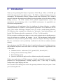
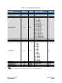
Table 3-1: Performance Characteristics1
Parameter
Value
Accuracy
Heading
<0.3° rms
≤80° of pitch after Full-Range
Calibration
<0.5° rms
≤5° of pitch after 2D calibration
<2.0° rms
≤2 times the calibration tilt angle when
using limited-tilt calibration2
<2.0° rms
Resolution
0.1°
Repeatability
0.05° rms
Range
Attitude
≤65° of pitch after Full-Range
Calibration
Accuracy
Pitch
± 90°
Roll
± 180°
Pitch
0.2° rms
Roll
≤65° of pitch
0.2° rms
≤80° of pitch
0.4° rms
≤86° of pitch
1.0° rms
Resolution
0.01°
Repeatability
Maximum Operational Dip Angle
Magnetometers
0.05° rms
3
85°
Calibrated Field Range
± 125 µT
Resolution
0.05 µT
Repeatability
± 0.1 µT
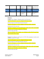
Footnotes:
1. Specifications are subject to change. Assumes the TCM is motionless and the local magnetic
field is clean relative to the user calibration.
2. For example, if the calibration was performed over ±10° of tilt, then the TCM would provide <2°
rms accuracy over ±20° of tilt.
3. Performance at maximum operational dip angle will be somewhat degraded.
PNI Sensor Corporation
TCM User Manual
DOC#1014688 r09
Page 3
Table 3-2: Absolute Maximum Ratings
Parameter
Supply Voltage
Storage Temperature
Minimum
Maximum
Units
-0.3
-40
+10
+85
VDC
°C
CAUTION:
Stresses beyond those listed above may cause permanent damage to the device. These are
stress ratings only. Operation of the device at these or other conditions beyond those
indicated in the operational sections of the specifications is not implied.
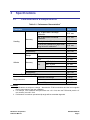
Table 3-3: Electrical Operating Requirements
Parameter
Supply Voltage
Communication
Lines
Average
Current Draw
Peak Current
Draw
Sleep Mode
Current Draw
PNI Sensor Corporation
TCM User Manual
Value
TCM XB
TCM MB
High Level Input
Low Level Input
TCM XB
Output Voltage Swing
Tx Output Resistance
High Level Input
Low Level Input
TCM MB
Output Voltage Swing
Tx Output Resistance
@ max. sample rate
TCM XB
@ 8 Hz sample rate
@ max. sample rate
TCM MB
@ 8 Hz sample rate
During application of external
power
During logical power up/down or
Sync Trigger
TCM XB
TCM MB
3.8 to 9 VDC
3.3 to 9 VDC
2.4 V minimum
0.6 V maximum
±5.2 V typ., ±5.0 V min.
300 Ω
2.0 V minimum
0.8 V maximum
0 – 3.3 V typical
330 Ω
20 mA typical
16 mA typical
17 mA typical
13 mA typical
120 mA pk, 60 mA avg
over 2 ms
135 mA pk, 60 mA avg
over 4 ms
0.3 mA typical
0.1 mA typical
DOC#1014688 r09
Page 4
Table 3-4: I/O Characteristics
Parameter
Value
TCM XB
Communication
Interface
TCM MB
Communication Protocol
Communication Rate
Maximum Sample Rate1
Initial power up
Time to Initial
Good Data2
Sleep Mode recovery
RS232 UART
CMOS/TTL UART
PNI Binary
300 to 115200 baud
~30 samples/sec
<210 ms
<80 ms
Footnotes:
1. The maximum sample rate is dependent on the strength of the magnetic
field, and typically will be from 25 to 32 samples/sec.
2. FIR taps set to “0”.
Table 3-5: Environmental Requirements
Parameter
Value
Operating Temperature
Storage Temperature
1
-40C to +85C
-40C to +85C
Footnote:
1. To meet performance specifications across this range,
recalibration will be necessary as the temperature varies.
Table 3-6: Mechanical Characteristics
Parameter
Dimensions
(l x w x h)
Weight
Connector
PNI Sensor Corporation
TCM User Manual
Value
TCM XB
TCM MB
TCM XB
TCM MB
TCM XB
TCM MB
35 x 43 x 13 mm
33 x 31 x 13 mm
6.8 gm
5.3 gm
9-pin Molex, pn 53780-0970
4-pin MIL-MAX, pn 850-10-004-10-001000
DOC#1014688 r09
Page 5
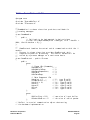
3.2
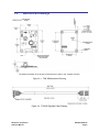
Mechanical Drawings
The default orientation is for the silk-screened arrow to point in the “forward” direction.
Figure 3-1: TCM XB Mechanical Drawing
Figure 3-2: TCM XB Pigtailed Cable Drawing
PNI Sensor Corporation
TCM User Manual
DOC#1014688 r09
Page 6
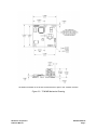
The default orientation is for the silk-screened arrow to point in the “forward” direction.
Figure 3-3: TCM MB Mechanical Drawing
PNI Sensor Corporation
TCM User Manual
DOC#1014688 r09
Page 7
4
Set-Up
This section describes how to configure the TCM in your host system. To install the TCM into
your system, follow these steps:
Make electrical connections to the TCM.
Evaluate the TCM using TCM Studio or a binary terminal emulation program, such as
RealTerm or Tera Term, to ensure the compass generally works correctly.
Choose a mounting location.
Mechanically mount the TCM in the host system.
Perform a user calibration.
4.1
Electrical Connections
The TCM XB incorporates a 9 pin Molex connector, part number 53780-0970, which mates
with Molex part 51146-0900 or equivalent. The TCM MB incorporates a 4 pin Mil-Max
connector, part number 850-10-004-10-001000, which mates with Mill-Max part 851-XX004-10-001000 or equivalent. The pin-out is given below in Table 4-1.
Table 4-1: TCM Pin Descriptions
Pin
Number1
1
2
3
4
5
6
7
8
9
TCM XB
TCM MB
9 Pin
Connector
Cable Wire
Color
4 Pin
Connector
GND
GND
GND
NC
NC
NC
UART Tx
UART Rx
Vin
Black
Gray
Green
Orange
Violet
Brown
Yellow
Blue
Red
GND
Vin
UART Tx
UART Rx
Footnote:
1. For the TCM XB, pin #1 is indicated on Figure 3-1, while for the TCM MB, pin
#1 is the pin closest to the corner.
After making the electrical connections, it is a good idea to perform some simple tests to
ensure the TCM is working as expected. See Section 5 for how to operate the TCM with
TCM Studio, or Section 7 for how to operate the TCM using the PNI binary protocol.
PNI Sensor Corporation
TCM User Manual
DOC#1014688 r09
Page 8
4.2
Installation Location
The TCM’s wide dynamic range and sophisticated calibration algorithms allow it to operate
in many environments. For optimal performance however, you should mount the TCM with
the following considerations in mind:
4.2.1
Operate within the TCM’s dynamic range
The TCM can be user calibrated to correct for static magnetic fields created by the host
system. However, each axis of the TCM has a calibrated dynamic range of ±125 µT. If
the total field exceeds this value for any axis, the TCM may not perform to specification.
When mounting the TCM, consider the effect of any sources of magnetic fields in the
host environment that, when added to Earth’s field, may take the TCM out of its dynamic
regime. For example, large masses of ferrous metals such as transformers and vehicle
chassis, large electric currents, permanent magnets such as electric motors, and so on.
4.2.2
Locate away from changing magnetic fields
It is not possible to calibrate for changing magnetic anomalies. Thus, for greatest
accuracy, keep the TCM away from sources of local magnetic distortion that will change
with time; such as electrical equipment that will be turned on and off, or ferrous bodies
that will move. Make sure the TCM is not mounted close to cargo or payload areas that
may be loaded with large sources of local magnetic fields.
4.2.3
Mount in a physically stable location
Choose a location that is isolated from excessive shock, oscillation, and vibration. The
TCM works best when stationary. Any non-gravitational acceleration results in a
distorted reading of Earth’s gravitational vector, which affects the heading measurement.
4.2.4
Location-verification testing
Location-verification testing should be performed at an early stage of development to
understand and accommodate the magnetic distortion contributors in a host system.
Determine the distance range of field distortion.
Place the compass in a fixed position, then move or energize suspect components
while observing the output to determine when they are an influence.
PNI Sensor Corporation
TCM User Manual
DOC#1014688 r09
Page 9
Determine if the magnetic field is within the dynamic range of the compass.
With the compass mounted, rotate and tilt the system in as many positions as
possible. While doing so, monitor the magnetometer outputs, observing if the
maximum linear range is exceeded.
4.3
Mechanical Mounting
The TCM is factory calibrated with respect to its mounting holes. It must be aligned within
the host system with respect to these mounting holes. Ensure any stand-offs or screws used
to mount the module are non-magnetic. Refer to Section 3.2 for dimensions, hole locations,
and the reference frame orientation.
Note: Ensure that when attaching the TCM to the host system, the mounting method does not
introduce stresses on the board, as this can affect the performance of the accelerometer, and
therefore also negatively affect heading accuracy.
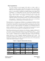
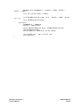
4.3.1
Pitch and Roll Conventions
The TCM uses a MEMS accelerometer to measure the tilt angle of the compass. This
data is output as pitch and roll data, and is also used in conjunction with the
magnetometers to provide a tilt-compensated heading reading.
The TCM utilizes Euler angles as the method for determining accurate orientation. This
method is the same used in aircraft orientation where the outputs are heading (also called
yaw or azimuth), pitch and roll. When using Euler angles, roll is defined as the angle
rotated around an axis through the center of the fuselage while pitch is rotation around an
axis through the center of the wings. These two rotations are independent of each other
since the rotation axes rotate with the plane body.
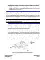
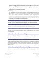
As shown in Figure 4-1, for the TCM a positive pitch is when the front edge of the board
is rotated upward and a positive roll is when the right edge of the board is rotated down.
Figure 4-1: Positive & Negative Roll and Pitch Definition
PNI Sensor Corporation
TCM User Manual
DOC#1014688 r09
Page 10
4.3.2
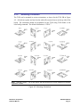
Mounting Orientation
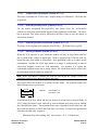
The TCM can be mounted in various orientations, as shown for the TCM XB in Figure
4-2. All reference points are based on the white silk-screened arrow on the top side of the
board. The orientation should be programmed in the TCM using TCM Studio or the
kSetConfig command. The default orientation is “STD 0°”.
Note: TCM XB is shown. The Z axis sensor and the connector are on the module’s top surface,
regardless of model.
Figure 4-2: Mounting Orientations
PNI Sensor Corporation
TCM User Manual
DOC#1014688 r09
Page 11
5
User Calibration
The magnetic sensors in the TCM are calibrated at PNI’s factory in a magnetically controlled
environment. However sources of magnetic distortion positioned near the TCM in the user’s
system will distort Earth’s magnetic field and should be compensated for in the host system with
a user calibration. Examples of such sources include ferrous metals and alloys (ex. iron, nickel,
steel, etc.), batteries, audio speakers, current-carrying wires, and electric motors. Compensation
is accomplished by mounting the TCM in the host system and performing a user calibration. It is
expected the sources of magnetic distortion remain fixed relative to the TCM’s position within
the host system. By performing a calibration, the TCM identifies the local sources of magnetic
distortion and negates their effects from the overall reading to provide an accurate heading.
As with the magnetic sensor, the accelerometer in the TCM is calibrated at PNI’s factory. But
the accelerometer will gradually change over time, and the user either will need to periodically
perform a user accelerometer calibration or return the unit to PNI for recalibration. As a general
rule-of-thumb, the accelerometer should be recalibrated every 6 to 12 months. Unlike a
magnetic calibration, the accelerometer may be calibrated outside the host system.
Accelerometer calibration is more sensitive to noise or hand jitter than magnetic calibration,
especially for subsequent use at high tilt angles. Because of this, ideally a stabilized fixture
would be used for accelerometer calibration, although resting the unit against a stable surface
often is sufficient.
Key Points:
Magnetic calibration:
o Requires incorporating the TCM into the host system to compensate for magnetic
sourcing and distorting components with the user’s system.
o Allows for 4 different methods of calibration. Full-Range Calibration provides
the highest heading accuracy, while 2D and Limited-Tilt Calibration support a
limited range of motion during calibration. Hard-Iron-Only Calibration updates
just the hard-iron coefficients with a relatively easy procedure.
Accelerometer calibration requires rotating the TCM through a full sphere of coverage,
but the TCM does not need to be incorporated into the user’s system during calibration.
If the TCM will experience different states during operation, such as operating with a
nearby shutter sometimes closed and sometimes open, or operating over a broad
temperature range, then different sets of calibration coefficients can be saved for the
various states. Up to 8 magnetic calibration coefficient sets and 3 accelerometer
calibration coefficient sets can be saved.
PNI Sensor Corporation
TCM User Manual
DOC#1014688 r09
Page 12
5.1
Magnetic Calibration
Two fundamental types of magnetic distortion exist, hard-iron distortion and soft-iron
distortion. A given component can exhibit both hard-iron and soft-iron distortions. These
distortions are reviewed in the ensuing paragraphs, and are followed by discussions on
temperature effects and other considerations. For more information on magnetic distortion
and calibration, see PNI’s white paper “Local Magnetic Distortion Effects on 3-Axis
Compassing” at PNI’s website (http://www.pnicorp.com/technology/papers).
Hard-Iron Effects
Hard-iron distortions are caused by permanent magnets and magnetized objects in
close proximity to the sensors. These distortions add or subtract a fixed component to
each axis of the magnetic field reading. Hard-iron distortions usually are unchanging
and in a constant location relative to the sensors, for all heading orientations.
Soft-Iron Effects
Magnetically “soft” materials effectively bend the magnetic field near them. These
materials have a high magnetic permeability, meaning they easily serve as a path for
magnetic field lines. Unlike hard-iron effects, soft-iron effects do not increase or
decrease the total field in the area. However, the effect of the soft-iron distortion
changes as the host system’s orientation changes. Because of this, it is more difficult
to compensate for soft-iron materials.
Temperature Effects
While the hard-iron and soft-iron distortion of a system may remain quite stable over
time, normally the distortion signature will change over temperature. As a general
rule, the hard-iron component will change 1% per 10°C temperature change. Exactly
how this affects heading depends on several factors, most notably the hard-iron
component of the system and the inclination, or dip angle.
Consider the example of a host system with a 100 µT hard-iron component. This is a
fairly large hard-iron component, but not completely uncommon. A 10°C
temperature change will alter the magnetic field by ~1 µT in the direction of the hardiron component. Around San Francisco, with an inclination of ~60°, this results in up
to a couple of degrees of heading change over 10°C.
Consequently, no matter how stable a compass is over temperature, it is wise to
recalibrate over temperature since the magnetic signature of the host system will
change over temperature. The TCM helps accommodate this issue by allowing the
user to save up to 8 sets of magnetic calibration coefficient sets, so different
calibration coefficients can be generated and loaded at different temperatures.
PNI Sensor Corporation
TCM User Manual
DOC#1014688 r09
Page 13
Other Considerations
The TCM measures the total magnetic field within its vicinity, which is a
combination of Earth’s magnetic field and local magnetic sources and distortions.
While the TCM’s calibration algorithms can compensate for local static magnetic
sources, it is not possible to compensate for dynamic changes in the magnetic field.
Consequently, it is recommended to keep the TCM away from dynamic magnetic
fields. If this is not possible, then take measurements only when the state of the
magnetic field is known. For example, if an electric motor is nearby take
measurements only when the motor is off. Alternatively, different sets of magnetic
calibration coefficients can be generated in advance for various states and then called
when appropriate. Using the prior example, generate and use one set of coefficients
for when the motor is off and another set for when the motor is on.
The main objective of a magnetic user calibration is to compensate for hard-iron and softiron distortions to the magnetic field caused by components within the user’s host system.
To that end, the TCM needs to be mounted within the host system and the entire host system
needs to be moved as a single unit during a user calibration. The TCM allows the user to
perform a calibration only in a 2D plane or with limited tilt, but provides the greatest
accuracy if the user can rotate through 360° of heading and at least ±45°of tilt.
The following subsections provide instructions for performing a magnetic calibration of a
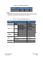
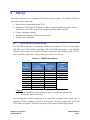
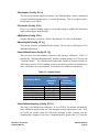
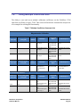
TCM system. Several calibration mode options exist, as summarized in Table 5-1. To meet
the accuracy specification, the number of samples should be the “Minimum Recommended”
value, or greater. Calibration may be performed using Studio or using the PNI binary
protocol, and up to 8 sets of magnetic calibration coefficients may be saved. The
recommended calibration patterns described in the following sub-sections provide a good
distribution of sample points. Also, PNI recommends the location of the TCM remain fairly
constant while only the orientation is changed.
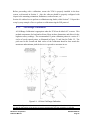
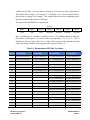
Table 5-1: Magnetic Calibration Mode Summary
Number of Samples
Calibration
Mode
Full Range
2D Calibration
Limited Tilt
Range
Hard Iron Only
PNI Sensor Corporation
TCM User Manual
Accuracy
0.3° rms
<2°
<2° over 2x tilt
range
Restores prior
accuracy
Tilt Range
during Cal
Minimum
Recommend
Allowable
Range
>±45°
<±5°
12
12
±5° to ±45°
12
10 – 18
10 – 18
10 – 18
>±3°
6
4 - 18
DOC#1014688 r09
Page 14
Before proceeding with a calibration, ensure the TCM is properly installed in the host
system, as discussed in Section 4. Also, the software should be properly configured with
respect to the mounting orientation, Endianness, north reference, etc.
Section 6.4 outlines how to perform a calibration using Studio, while Section 7.3.10 provides
a step-by-step example of how to perform a calibration using the PNI protocol.
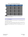
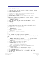
5.1.1
Full-Range Calibration
A Full-Range Calibration is appropriate when the TCM can be tilted ±45° or more. This
method compensates for hard and soft iron effects in three dimensions, and allows for the
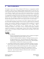
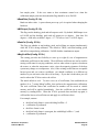
highest accuracy readings. The recommended 12 point calibration pattern is a series of 3
circles of evenly spaced points, as illustrated in Figure 5-1 and listed in Table 5-2. The
pitch used in the second and third circles of the calibration should at least match the
maximum and minimum pitch the device is expected to encounter in use.
Figure 5-1: 12 Point Full-Range Calibration
Note: While Figure 5-1 shows the location of the device changing, this is for illustration purposes and
it is best for the location of the device to remain constant while only the orientation is changed.
PNI Sensor Corporation
TCM User Manual
DOC#1014688 r09
Page 15
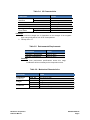
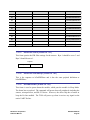
Table 5-2: 12 Point Full-Range Calibration Pattern
Sample #
Yaw1
Pitch
Roll
0°
90°
180°
270°
±5°
±5°
±5°
±5°
30° to 40°
-30° to -40°
30° to 40°
-30° to -40°
30°
120°
210°
300°
> +45°
> +45°
> +45°
> +45°
30° to 40°
-30° to -40°
30° to 40°
-30° to -40°
60°
150°
240°
330°
< -45°
< -45°
< -45°
< -45°
30° to 40°
-30° to -40°
30° to 40°
-30° to -40°
First Circle
1
2
3
4
Second Circle
5
6
7
8
Third Circle
9
10
11
12
Footnote:
1. Yaw listings are not absolute heading directions but rather relative heading
referenced to the first sample.
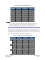
5.1.2
2D Calibration
A 2D Calibration is intended for very low tilt operation (<5°) where calibrating the TCM
with greater tilt is not practical.
This procedure calibrates for hard and soft iron effects in only two dimensions, and in
general is effective for operation and calibration in the tilt range of -5° to +5°. The
recommended 12 point calibration pattern is a circle of evenly spaced points, as given in
Table 5-3.
PNI Sensor Corporation
TCM User Manual
DOC#1014688 r09
Page 16
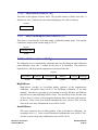
Table 5-3: 12 Point 2D Calibration Pattern
Sample #
Yaw
Pitch1
Roll1
1
2
3
4
5
6
7
8
9
10
11
12
0°
30°
60°
90°
120°
150°
180°
210°
240°
270°
300°
330°
0°
max. negative
0°
max. positive
0°
max. negative
0°
max. positive
0°
max. negative
0°
max. positive
0°
max. negative
0°
max. positive
0°
max. negative
0°
max. positive
0°
max. negative
0°
max. positive
Footnote:
1. For best results, the tilt experienced during calibration should match that experienced
in service. For example, if the TCM is restrained to a level plane in service, then
calibration should be in a plane, where “max. positive” and “max. negative” are 0°.
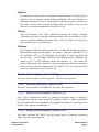
5.1.3
Limited Tilt Range Calibration
A Limited Tilt Range Calibration is recommended when 45° of tilt isn’t feasible, but >5°
of tilt is possible. It provides both hard-iron and softiron distortion correction. The
recommended 12 point calibration pattern given below is a series of 3 circles of evenly
spaced points, with as much tilt variation as expected during use.
Table 5-4: 12 Point Limited-Tilt Calibration Pattern
Sample #
First Circle
1
2
3
6
Second Circle
7
8
11
12
Third Circle
13
14
17
18
PNI Sensor Corporation
TCM User Manual
Yaw
Pitch
Roll
0°
90°
180°
270°
0°
0°
0°
0°
0°
0°
0°
0°
45°
135°
225°
315°
> +5°
> +5°
> +5°
> +5°
> +5°
> +5°
> +5°
> +5°
45°
135°
225°
315°
< -5°
< -5°
< -5°
< -5°
< -5°
< -5°
< -5°
< -5°
DOC#1014688 r09
Page 17
Note that a similar and acceptable alternative pattern would be to follow the
recommended 12 point Full-Range Calibration pattern, but substituting the >±45° of pitch
with whatever pitch can be achieved and the ±10° to ±20° or roll with whatever roll can
be achieved up to these limits.
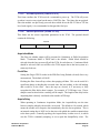
5.1.4
Hard-Iron-Only Calibration
It is not uncommon for the hard-iron magnetic distortions around the TCM to change.
Some reasons for this include significant temperature change or temperature shock to a
system, as well as gradual aging of components. A Hard-Iron-Only Calibration allows
for quick recalibration of the TCM for hard-iron effects, and generally is effective for
operation and calibration in the tilt range of 3° or more (≥45° is preferred). The
recommended 6 point calibration pattern given below is a circle of alternately tilted,
evenly spaced points, with as much tilt as expected during use.
Table 5-5: 6 Point Hard-Iron-Only Calibration Pattern
Sample #
Yaw
Pitch1
Roll1
1
2
3
4
5
6
0°
60°
120°
180°
240°
300°
max. negative
max. positive
max. negative
max. positive
max. negative
max. positive
max. negative
max. positive
max. negative
max. positive
max. negative
max. positive
Footnote:
1. For best results, the tilt experienced during calibration should match that experienced
in service. For example, if the TCM will be subject to ±45° of pitch and roll when in
service, then “max negative” should be -45° and “max positive” should be +45°.
5.2 Accelerometer Calibration
The TCM uses a MEMS accelerometer to measure the attitude of the compass. This data is
output as pitch and roll data. Additionally, the accelerometer data is critical for establishing
an accurate heading reading when the TCM is tilted, as discussed in the PNI white paper
“Tilt-Induced Heading Error in a 2-Axis Compass”, which can be found on PNI’s web site
(http://www.pnicorp.com/technology/papers).
The TCM algorithms assume the accelerometer only measures the gravitational field. If the
TCM is accelerating, this will result in the TCM calculating an inaccurate gravitational
PNI Sensor Corporation
TCM User Manual
DOC#1014688 r09
Page 18
vector, which in turn will result in an inaccurate heading reading. For this reason, the TCM
should be stationary when taking a measurement.
As previously mentioned, PNI calibrates the accelerometer in its factory prior to shipment.
But over time the bias and offset of the accelerometer will drift. For this reason PNI
recommends the accelerometer be recalibrated every 6 to 12 months. The user may return
the TCM to PNI for accelerometer calibration, or the user may perform a user accelerometer
calibration. The remainder of this section covers the user accelerometer calibration.
5.2.1
Accelerometer-Only Calibration
The requirements for a good user accelerometer calibration differ significantly from the
requirements for a good magnetic calibration. Specifically, a good accelerometer
calibration involves the TCM experiencing a wide range of pitch and roll values,
preferably seeing both ±180° of pitch and ±180° of roll. Also, it is necessary for the
TCM to be very still during an accelerometer calibration. If possible, PNI recommends
using a fixture to hold the device during calibration, although resting the TCM on a hard
surface normally is sufficient.
The accelerometer either can be calibrated while mounted in the host system or it may be
removed and calibrated outside the system. The advantage of performing the calibration
while mounted in the host system is the user does not need to remove the TCM from the
system, which can be burdensome, and a simultaneous Mag-and-Accel Calibration may
be appropriate. The advantage of performing the calibration outside of the system is it
may be much simpler to obtain the desired range of pitch and roll.
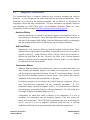
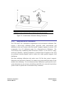
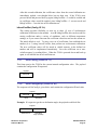
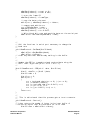
Figure 5-2 shows the two basic starting positions for the recommended 18-point
calibration pattern. Starting with the TCM as shown on the left in Figure 5-2, rotate the
device about its z axis such that it sits on each of its 4 edges, taking one calibration
sample on each edge. Then place the TCM flat on the surface and take a calibration
sample, then flip it over (roll it 180°) and take another sample. Next, starting with the
TCM as shown on the right, take a calibration point with it being vertical (0°). Now tilt
the TCM back 45° and take another calibration point (+45°), then tilt the device forward
45° and take another calibration point (-45°). Repeat this 3-point calibration process for
the TCM with it resting on each of its 4 corners. Note that it is possible to perform an
Accelerometer Calibration with as few as 12 sample points, although it generally is more
difficult to obtain a good calibration with just 12 sample points. Also, the maximum
number of calibration points is 18.
PNI Sensor Corporation
TCM User Manual
DOC#1014688 r09
Page 19
Note: While the TCM is shown removed from the host system, the Accelerometer
Calibration may be performed with the TCM mounted in the host system.
Figure 5-2: Accelerometer Calibration Starting Orientations
5.2.2
Mag-and-Accel Calibration
The TCM allows for a simultaneous magnetometer and accelerometer calibration. This
requires a full-coverage calibration pattern, physically stable measurements, and
installation in the user’s system so the host system’s magnetic signature is present. PNI
recommends 18 to 32 calibration points for a Mag-and-Accel Calibration. The
Accelerometer-Only Calibration pattern discussed in Section 5.2 will work for a Magand-Accel Calibration. Optimal performance is obtained when all rotations of the TCM
are performed towards magnetic north to achieve the widest possible magnetic field
distribution.
Note that combining calibrations only makes sense if all the host system’s magnetic
distortions (steel structures or batteries, for instance) are present and fixed relative to the
module when calibrating. If an Accelerometer-Only Calibration is performed, the user’s
system distortions are not relevant, which allows the TCM to be removed from the host
system in order to perform the Accelerometer-Only Calibration.
PNI Sensor Corporation
TCM User Manual
DOC#1014688 r09
Page 20
6
Operation with TCM Studio
TCM Studio puts an easy-to-use, graphical-user interface (GUI) onto the binary command
language used by the TCM. TCM Studio is intended for evaluating, demonstrating, and
calibrating the TCM module. The program includes the ability to log and save the outputs from
the TCM to a file for off-line evaluation. Check the PNI website for the latest TCM Studio
updates at www.pnicorp.com.
Note: TCM Studio v3.X and higher is compatible with the TCM XB, TCM MB and legacy TCM 6, but not
other legacy TCM models. The TCM XB also will work with TCM Studio v3 and higher, while the TCM
MB will work with TCM Studio v4 and higher. The version of Studio is identified in the upper left corner of
the GUI.
The TCM Studio evaluation software communicates with the TCM through the RS232 serial port
of a computer. The TCM MB requires a user-supplied level shifter to make it compatible with
the computer’s RS232 interface.
6.1
Installation
TCM Studio is provided as an executable program which can be downloaded from PNI’s
website. It will work with Windows XP, Windows Vista, Windows 7, and Mac OS X
operating systems. Check the PNI web page at www.pnicorp.com for the latest version.
For Windows computers, copy the TCMStudio.msi file onto your computer. Then, open the
file and step through the Setup Wizard.
For Mac computers, copy the TCMStudio.zip file onto your computer. This automatically
places the application in the working directory of your computer. The Quesa plug-in, also in
the .zip file, needs to be moved to /Library/CFMSupport, if it is not already there.
PNI Sensor Corporation
TCM User Manual
DOC#1014688 r09
Page 21
6.2
Connection Tab
6.2.1
Initial Connection
If using the PNI dual-connectorized cable, ensure the batteries are well-charged.
Select the serial port the module is plugged into, which is generally COM 1.
Select 38400 as the baud rate.
Click the <Connect> button if the connection is not automatic.
Once a connection is made the “Connected” light will turn green and the module’s
firmware version, serial number, and PCA version will be displayed in the header section.
6.2.2
Changing Baud Rate
To change the baud rate:
In the Module window, select the new baud rate for the module.
Click the <Power Down> button. The button will change to read <Power Up>.
In the Computer window, select same baud rate for the computer.
Click the <Power Up> button. The button will revert back to <Power Down>.
Note: While the TCM can operate at a baud rate of 230400, a PC serial port normally will not
operate this fast.
PNI Sensor Corporation
TCM User Manual
DOC#1014688 r09
Page 22
6.2.3
Changing Modules
Once a connection has been made, TCM Studio will recall the last settings. If a different
module is used, click the <Connect> button once the new module is attached. This will
reestablish a connection, assuming the module baud rate is unchanged.
6.3
Configuration Tab
Note: No settings will be changed in the module until the <SAVE> button has been selected.
6.3.1
Mounting Options
TCM Studio supports 16 mounting orientations, as illustrated previously in Figure 4-2.
The descriptions in TCM Studio are slightly different from those shown in Figure 4-2,
and the relationship between the two sets of descriptions is given below.
PNI Sensor Corporation
TCM User Manual
DOC#1014688 r09
Page 23
Table 6-1: Mounting Orientations
TCM Studio
Description
Figure 4-2
Description
TCM Studio
Description
Figure 4-2
Description
Standard
Standard 90
Degrees
Standard 180
Degrees
Standard 270
Degrees
X Sensor Up
X Sensor Up Plus
90 Degrees
X Sensor Up Plus
180 Degrees
X Sensor Up Plus
270 Degrees
STD 0°
Y Sensor Up
Y Sensor Up Plus
90 Degrees
Y Sensor Up Plus
180 Degrees
Y Sensor Up Plus
270 Degrees
Z Sensor Down
Z Sensor Down
Plus 90 Degrees
Z Sensor Down
Plus 180 Degrees
Z Sensor Up Plus
270 Degrees
“Y” Up 0°
6.3.2
STD 90°
STD 180°
STD 270°
“X” Up 0°
“X” Up 90°
“X” Up 180°
“X” Up 270°
“Y” Up 90°
“Y” Up 180°
“Y” Up 270°
“Z” Down 0°
“Z” Down 90°
“Z” Down 180°
“Z” Down 270°
North Reference
Declination, also called magnetic variation, is the difference between true and magnetic
north. It is measured in degrees east or west of true north. Correcting for declination is
accomplished by storing the correct declination angle, and then changing the heading
reference from magnetic north to true north. Declination angles vary throughout the
world, and change very slowly over time. For the greatest possible accuracy, go to the
National Geophysical Data Center web page below to get the declination angle based on
your latitude and longitude:
http://www.ngdc.noaa.gov/geomagmodels/Declination.jsp
Magnetic
When the <Magnetic> button is selected, heading will be relative to magnetic north.
True
When the <True> button is selected, heading will be relative to true north. In this
case, the declination needs to be set in the “Declination” window.
6.3.3
Endianess
Select either the <Big> or <Little> Endian button. The default setting is <Big>. See
Sections 7.2 and 7.3 for additional information.
PNI Sensor Corporation
TCM User Manual
DOC#1014688 r09
Page 24
6.3.4
Output
The TCM module can output heading, pitch, and roll in either degrees or mils. Click
either the <Degrees> or <Mils> button. The default is <Degrees>. (There are 6400 mils
in a circle, such that 1 degree = 17.7778 mils and 1 mil = 0.05625 degree.)
6.3.5
Enable 3D Model
TCM Studio’s Test tab includes a live-action 3-D rendering of a helicopter. Some
computer systems may not have the graphics capability to render the 3D Model, for this
reason it may be necessary to turn off this feature.
6.3.6
Filter Setting (Taps)
The TCM incorporates a finite impulse response (FIR) filter to effectively provide a more
stable heading reading. The number of taps (or samples) represents the amount of
filtering to be performed. The user should select either 0, 4, 8, 16, or 32 taps, with zero
taps representing no filtering. Note that selecting a larger number of taps can
significantly slow the time for the initial sample reading and, if “Flush Filters” is
selected, the rate at which data is output. The default setting is 32.
6.3.7
Acquisition Settings
Mode
When operating in Continuous Acquisition Mode, the TCM continuously outputs data
to the host system. The rate is set by the Sample Delay. When operating in Poll
Mode, TCM Studio simulates a host system and polls the TCM for a single
measurement; but TCM Studio makes this request at a fixed rate which is set by the
Poll Delay. In both cases data is continuously output, but in Continuous Mode the
TCM controls the data rate while in Poll Mode the TCM Studio program controls the
data rate. Poll Mode is the default.
Poll Delay
The Poll Delay is relevant when Poll Mode is selected. It represents the time delay,
in seconds, between the completion of TCM Studio receiving one set of sampled data
and requesting the next sample set. If the delay is set to 0, then TCM Studio requests
new data as soon as the previous request is fulfilled. Note that the inverse of the Poll
Delay is greater than the sample rate, since the Poll Delay does not include the actual
measurement acquisition time. The default is 0.
PNI Sensor Corporation
TCM User Manual
DOC#1014688 r09
Page 25
Acquire Delay
The Acquire Delay sets the time between samples taken by the module, in seconds.
This is an internal setting that is NOT tied to the time with which the module
transmits data to TCM Studio or the host system. Generally speaking, the Acquire
Delay is either set to 0, in which case the TCM is constantly sampling or set to equal
either the Poll Delay or Sample Delay values. The advantage of running with an
Acquire Delay of 0 is that the FIR filter can run with a relatively high Tap value to
provide stable and timely data. The advantage of using a greater Acquire Delay is
that power consumption can be reduced, assuming the Sample or Poll Delay are no
less than the Acquire Delay.
Sample Delay
The Sample Delay is relevant when Continuous Mode is selected. It is the time
delay, in seconds, between completion of the TCM sending one set of data and the
start of sending the next sample set. If the delay is set to 0, then the TCM will begin
sending new data as soon as the previous data set has been sent. Note that the inverse
of the Sample Delay is greater than the sample rate, since the Sample Delay does not
include the actual measurement acquisition time. The default is 0.
Flush Filters
Flushing the FIR filter clears all the filter values so it is necessary to fully repopulate
the filter before a good reading can be given. For example, if 32 FIR taps is set, then
32 new samples must be taken to provide a good reading. It is particularly prudent to
flush the filter if the Sample Delay is set to a non-zero value as this will purge old
data. Note that flushing the filters increases the delay until data is output, with the
length of the delay being directly correlated to the number of FIR taps. The default is
not to Flush Filters.
6.3.8
HPR During Calibration
When the <On> button is selected, heading, pitch, and roll will be output on the
Calibration tab during a calibration.
6.3.9
Calibration Settings
Automatic Sampling
When selected, the module will take a sample point once the minimum change and
stability requirements have been satisfied. If the user wants to have more control
over when the point will be taken, then Auto Sampling should be deselected. Once
deselected, the <Take Sample> button on the Calibration tab will be active. Selecting
PNI Sensor Corporation
TCM User Manual
DOC#1014688 r09
Page 26
the <Take Sample> button will indicate to the module to take a sample once the
minimum change and stability requirements are met.
Calibration Points
Select the number of points to take during a calibration. The minimum recommended
number of points for an initial magnetic calibration is 12, although a Hard-Iron-Only
(re)Calibration can be performed with only 6 recommended samples. The TCM will
need to be rotated through at least 180° in the horizontal plane with a minimum of at
least 1 positive and 1 negative Pitch and at least 1 positive and 1 negative Roll as part
of the 12 points.
Calibration Method Buttons
Full Range Calibration - recommended calibration method when >45° of tilt is
possible. The minimum recommended number of calibration points is 12.
HI Only Calibration - serves as a hard iron recalibration to a prior calibration. If the
hard iron distortion around the module has changed, this calibration can bring the
module back into specification. The minimum recommended number of calibration
points is 6.
Limited Tilt Range Calibration - recommended calibration method when >5° of tilt
calibration is available, but tilt is restricted to <45°. (i.e. Full-Range Calibration is
not possible.) The minimum recommended number of calibration points is 12.
2D Calibration - Recommended when the available tilt range is limited to ≤5°. The
minimum recommended number of calibration points is 12.
Accel Only Calibration – Select this when only an accelerometer calibration will be
performed. The minimum recommended number of calibration points is 18.
Accel Calibration with Mag – The user should select this when magnetometer and
accelerometer calibration will be performed simultaneously. The minimum
recommended number of calibration points is 18.
6.3.10
Default
Clicking this button restores the TCM Studio program to the factory default settings.
6.3.11
Retrieve
Clicking on this button causes TCM Studio to read the settings from the module and
display them on the screen.
PNI Sensor Corporation
TCM User Manual
DOC#1014688 r09
Page 27
6.4
Calibration Tab
Note: The default settings are recommended for the highest accuracy and quality of calibration.
6.4.1
Samples
Before proceeding, refer to Section 5 for the recommended calibration procedure
corresponding to the calibration method selected on the Configuration tab.
Clicking the <Start> button begins the calibration process.
If “Automatic Sampling” is not checked on the Configuration tab, it is necessary to click
the <Take Sample> button to take a calibration sample point. This should be repeated
until the total number of samples, as set on the Configuration tab, is taken while changing
the orientation of the module between samples as discussed in Section 5.
If “Automatic Sampling” is checked, the module will need to be held steady for a short
time and then a sample automatically will be taken. Once the window indicates the next
number, the module’s orientation should be changed and held steady for the next sample.
Once the pre-set number of samples has been taken (as set on the Configuration tab) the
calibration is complete.
PNI Sensor Corporation
TCM User Manual
DOC#1014688 r09
Page 28
6.4.2
Calibration Results
Once a calibration is complete, the “Calibration Results” window will indicate the quality
of the calibration. This may take a minute or more to populate. The primary purpose of
these scores is to confirm the calibration was successful, as indicated by a low Mag
and/or Accel CalScore. The other scores provide information that may assist in
improving the CalScore, should it be unacceptably high. If either CalScore is too high,
click the <Start> button to begin a new calibration. If the calibration is acceptable, click
the <Save> button to save the calibration to the module’s flash. If the <Save> button is
not selected then the module will need to be recalibrated after a power cycle.
Note: If a calibration is aborted, all the score’s will read “179.80”, and the calibration coefficients
will not be changed. (Clicking the <Save> button will not change the calibration coefficients.)
Mag CalScore
Represents the over-riding indicator of the quality of the magnetometer calibration.
Acceptable scores will be <1 for Full-Range Calibration, <2 for other methods. Note
that it is possible to get acceptable scores for Dist Error and Tilt Error and still have a
rather high Mag CalScore value. The most likely reason for this is the TCM is close
to a source of local magnetic distortion that is not fixed with respect to the module.
Dist Error
Indicates the quality of the sample point distribution, primarily looking for an even
yaw distribution. Significant clumping or a lack of sample points in a particular
section can result in a poor score. The score should be <1 and close to 0.
Tilt Error
Indicates the contribution to the Mag CalScore caused by tilt or lack thereof, and
takes into account the calibration method. The score should be <1 and close to 0.
Tilt Range
This reports the larger of either half the full pitch range or half the full roll range of
sample points. For example, if the module is pitched +10° to -20º, and rolled +25º to
-15º, the Tilt Range value would be 20º, as derived half the full roll range. For FullRange Calibration and Hard-Iron-Only Calibration, this should be ≥45°. For 2D
Calibration, this ideally should be ≈2°. For Limited Tilt Range Calibration the value
should be as large a possible given the user’s constraints.
Accel CalScore
Represents the over-riding indicator of the quality of the accelerometer calibration.
Acceptable scores will be <1.
PNI Sensor Corporation
TCM User Manual
DOC#1014688 r09
Page 29
6.4.3
Current Configuration
These indicators mimic the pertinent selections made on the Configuration tab.
6.4.4
Options
This window indicates how many samples are to be taken and provides real time heading,
pitch, and roll information if “HPR During Calibration” is set to <On>, both as defined
on the Configuration tab.
Audible Feedback
If selected TCM Studio will give an audible signal once a calibration point has been
taken. Note that an audible signal also will occur when the <Start> button is clicked,
but no data will be taken.
6.4.5
Clear
Clear Mag Cal to Factory
This button clears the user’s calibration of the magnetometers. Once selected, the
module reverts to its factory magnetometer calibration. To save this action in
nonvolatile memory, click the <Save> button. It is not necessary to clear the current
calibration in order to perform a new calibration.
Clear Accel Cal to Factory
This button clears the user’s calibration of the accelerometer. Once selected, the
module reverts back to its factory accelerometer calibration. To save this action in
non-volatile memory, click the <Save> button. It is not necessary to clear the current
calibration in order to perform a new calibration.
PNI Sensor Corporation
TCM User Manual
DOC#1014688 r09
Page 30
6.5
Test Tab
6.5.1
Current Reading
Once the <Go> button is selected the module will begin outputting heading, pitch and roll
information. Selecting the <Stop> button or changing tabs will halt the output of the
module.
Contrast
Selecting this box sets the “Current Readings” window to have yellow lettering on a
black background, rather than black lettering on a white background.
6.5.2
3D Model
The helicopter will follow the movement of the TCM and give a visual representation of
the module’s orientation, assuming the “Enable 3D Model Display” box is selected on the
Configuration tab.
6.5.3
Acquisition Settings
These indicators mimic the pertinent selections made on the Configuration tab.
PNI Sensor Corporation
TCM User Manual
DOC#1014688 r09
Page 31
6.5.4
Sync Mode
Sync Mode enables the module to stay in Sleep Mode until the user’s system sends a
trigger to report data. When so triggered, the TCM will wake up, report data once, then
return to Sleep Mode. One application of this is to lower power consumption. Another
use of the Sync Mode is to trigger a reading during an interval when local magnetic
sources are well understood. For instance, if a system has considerable magnetic noise
due to nearby motors, the Synch Mode can be used to take measurements when the
motors are turned off.
Enter Sync Mode
On the Test tab, above the tabs and 3D model, click the “Sync Mode” check box to
enter Sync Mode.
Sync Mode Output
To retrieve the first reading, click the <Sync Read> button. Heading, pitch and roll
information will be displayed on Current Reading window. If the “Enable 3D Model
Display” box is selected on the Configuration tab, then the helicopter will follow the
movement as well. The module will enter Sleep Mode after outputting the heading,
pitch, and roll information. To obtain subsequent readings, the user should first click
on the <Sync Trigger> button to wake up the module and then click on the <Sync
Read> button to get the readings, after which the module will return to sleep.
Exit Sync Mode
Click on the <Sync Trigger> button and then uncheck the “Sync Mode” check box to
exit Sync Mode.
Note that <Sync Trigger> sends a 0xFF signal as an external interrupt to wake up the
module. This is not done for the first reading as the module is already awake.
PNI Sensor Corporation
TCM User Manual
DOC#1014688 r09
Page 32
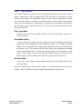
6.6
Log Data Tab
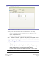
TCM Studio can capture measurement data and then export it to a text file. To acquire data
and export it, follow the procedure below:
Select the parameters you wish to log in the “Data” window. Use Shift -Click and
Ctrl-Click to select multiple items. In the screen shot above, “Heading”, “Pitch”, and
“Roll” were selected.
Click the <Go> button to start logging. The <Go> button changes to a <Stop> button
after data logging begins.
Click the <Stop> button to stop logging data.
Click the <Export> button to save the data to a file.
Click the <Clear> button to clear the data from the window.
Note: The data logger use ticks for time reference. A tick is 1/60 second.
PNI Sensor Corporation
TCM User Manual
DOC#1014688 r09
Page 33
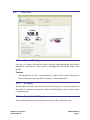
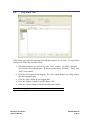
6.7
Graph Tab
The graph provides a 2-axis (X,Y) plot of the measured field strength. If “w/o User Cal”
graph data is selected, the plot and data provide magnetic field strength measurements after
the FIR taps are applied, but prior to applying the user calibration coefficients. If “with User
Cal” graph data is selected, the plot and data provide data after applying the FIR filter and the
user calibration coefficients. The sample plot shows a 360° rotation in the horizontal plane,
with both “w/o User Cal” and “with User Cal” selected. The offset between these two plots
represents the effect of the calibration coefficients. The graph can be used to visually see
hard and soft iron effects within the environment measured by the TCM, as well as corrected
output after a user calibration has been performed.
PNI Sensor Corporation
TCM User Manual
DOC#1014688 r09
Page 34
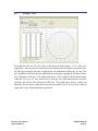
6.8
System Log Tab
The System Log tab shows all communication between TCM Studio and the TCM module
since launching TCM Studio. Closing TCM Studio will erase the system log. Select the
<Export> button, at the bottom right of the screen, to save the system log to a text file.
PNI Sensor Corporation
TCM User Manual
DOC#1014688 r09
Page 35
7
Operation with PNI Binary Protocol
The TCM utilizes a binary communication protocol, where the communication parameters
should be configured as follows:
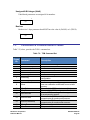
Table 7-1: UART Configuration
7.1
Parameter
Value
Number of Data Bits
Start Bits
Stop Bits
Parity
8
1
1
none
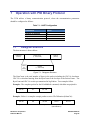
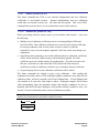
Datagram Structure
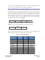
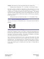
The data structure is shown below:
ByteCount
(UInt16)
Packet Frame
(1 - 4092 UInt8)
Frame
ID
(UInt8)
CRC-16
(UInt16)
Payload
(1 - 4091 UInt8)
Figure 7-1: Datagram Structure
The ByteCount is the total number of bytes in the packet including the CRC-16 checksum.
CRC-16 is calculated starting from the ByteCount to the last byte of the Packet Frame. The
ByteCount and CRC-16 are always transmitted in big Endian. Two examples follow.
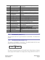
Example: The complete packet for the kGetModInfo command, which has no payload is:
00 05
01
EF D4
ByteCount
Frame ID
Checksum
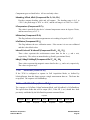
Example: Below is a complete sample packet to start a 2D Calibration (kStartCal):
00 09
0A
00 00
00 14
5C F9
ByteCount
Frame ID
CalOption
CalOption
(2D Calibration)
Checksum
PNI Sensor Corporation
TCM User Manual
DOC#1014688 r09
Page 36
7.2
Parameter Formats
Note: Floating-point based parameters conform to ANSIring/IEEE Std 754-1985. Please refer to the
Standard for more information. PNI also recommends refer to the user’s compiler instructions to
understand how the compiler implements floating-point format.
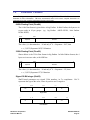
64-Bit Floating Point (Float64)
The 64-bit float format is given below in big Endian. In little Endian, the bytes are in
reverse order in 4 byte groups. (eg. big Endian: ABCD EFGH; little Endian:
DCBA HGFE).
63 62
S
52 51
0
Exponent
Mantissa
The value (v) is determined as: “if and only if” 0 < Exponent < 2047, then
v = (-1)*S*2(Exponent-1023)*1.Mantissa
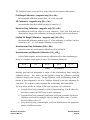
32-Bit Floating Point (Float32)
Shown below is the 32-bit float format in big Endian. In little Endian format, the 4
bytes are in reverse order, with LSB first.
3130
S
23 22
0
Exponent
Mantissa
The value (v) is determined as: “if and only if” 0 < Exponent < 255, then
v = (-1)*S*2(Exponent-127)*1.Mantissa
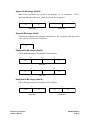
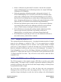
Signed 32-Bit Integer (SInt32)
SInt32-based parameters are signed 32-bit numbers, in 2’s compliment.
represents the sign of the value, where 0=positive and 1=negative.
31
24 23
16 15
8 7
msb
Bit 31
0
lsb
Big Endian
7
0 15
8 23
lsb
16 31
24
msb
Little Endian
PNI Sensor Corporation
TCM User Manual
DOC#1014688 r09
Page 37
Signed 16-Bit Integer (SInt16)
SInt16-based parameters are signed 16-bit numbers, in 2’s compliment.
represents the sign of the value, where 0=positive and 1=negative.
15
8 7
msb
0
7
0 15
8
lsb
lsb
Bit 15
msb
Little Endian
Big Endian
Signed 8-Bit Integer (SInt8)
UInt8-based parameters are unsigned 8-bit numbers. Bit 7 represents the sign of the
value, where 0=positive and 1=negative.
7
0
byte
Unsigned 32-Bit Integer (UInt32)
UInt32-based parameters are unsigned 32-bit numbers.
31
24 23
16 15
8 7
msb
0
lsb
Big Endian
7
0 15
8 23
16 31
lsb
24
msb
Little Endian
Unsigned 16-Bit Integer (UInt16)
UInt16-based parameters are unsigned 16-bit numbers.
15
8 7
msb
lsb
Big Endian
PNI Sensor Corporation
TCM User Manual
0
7
0 15
lsb
8
msb
Little Endian
DOC#1014688 r09
Page 38
Unsigned 8-Bit Integer (UInt8)
UInt8-based parameters are unsigned 8-bit numbers.
7
0
byte
Boolean
Boolean is a 1-byte parameter that MUST have the value 0 (FALSE) or 1 (TRUE).
7
0
byte
7.3
Commands & Communication Frames
Table 7-2, below, provides the TCM’s command set.
Table 7-2: TCM Command Set
Frame
Command
IDd
1
2
3
4
5
6
kGetModInfo
kGetModInfoResp
kSetDataComponents
kGetData
kGetDataResp
kSetConfig
7
kGetConfig
8
kGetConfigResp
9
kSave
10
11
kStartCal
kStopCal
12
kSetFIRFilters
13
kGetFIRFilters
14
kGetFIRFiltersResp
15
16
kPowerDown
kSaveDone
PNI Sensor Corporation
TCM User Manual
Description
Queries the device’s type and firmware revision.
Response to kGetModInfo
Sets the data components to be output.
Queries the TCM for data
Response to kGetData
Sets internal configurations in TCM
Queries TCM for the current internal
configuration
Response to kGetConfig
Saves the current internal configuration and any
new user calibration coefficients to non-volatile
memory.
Commands the TCM to start user calibration
Commands the TCM to stop user calibration
Sets the FIR filter settings for the magnetometer
& accelerometer sensors.
Queries for the FIR filter settings for the
magnetometer & accelerometer sensors.
Contains the FIR filter settings for the
magnetometer & accelerometer sensors.
Powers down the module
Response to kSave
DOC#1014688 r09
Page 39
17
kUserCalSampleCount
18
19
20
kCalScore
kSetConfigDone
kSetFIRFiltersDone
21
kStartContinuousMode
22
kStopContinuousMode
23
kPowerUpDone
24
25
26
27
28
kSetAcqParams
kGetAcqParams
kSetAcqParamsDone
kGetAcqParamsResp
kPowerDownDone
29
kFactoryMagCoeff
30
kFactoryMagCoeffDone
31
kTakeUserCalSample
36
kFactoryIAccelCoeff
37
kFactoryAccelCoeffDone
46
kSetSyncMode
47
49
kSetSyncModeResp
kSyncRead
7.3.1
Sent from the TCM after taking a calibration
sample point
Contains the calibration score
Response to kSetConfig
Response to kSetFIRFilters
Commands the TCM to output data at a fixed
interval
Stops data output when in Continuous Mode
Confirms the TCM has received a signal to
power up
Sets the sensor acquisition parameters
Queries for the sensor acquisition parameters
Response to kSetAcqParams
Response to kGetAcqParams
Response to kPowerDown
Resets magnetometer calibration coefficients to
original factory-established values
Response to kFactoryMagCoeff
Commands the TCM to take a sample during
user calibration
Resets accelerometer calibration coefficients to
original factory-established values
Respond to kFactoryAccelCoeff
Sets whether the TCM is in normal or Sync
Mode
Response to kSetSyncMode
Queries the module for data in Sync Mode
kGetModInfo (frame ID 1d)
This frame queries the device's type and firmware revision number. The frame has no
payload.
7.3.2
kGetModInfoResp (frame ID 2d)
The response to kGetModInfo is given below. The payload contains the device type
identifier followed by the firmware revision number.
Payload
Type
Revision
UInt32
UInt32
Note that the Type and Revision can be decoded from the binary format to character
format using the ASCII standard. For example, the hex string “00 0D 02 54 43 4D 35 31
PNI Sensor Corporation
TCM User Manual
DOC#1014688 r09
Page 40
32 30 38 C7 87” can be decoded to read “TCM5 1208”. Also, the TCM XB is referenced
as Type “TCM6” since the number of Type characters is limited to 4.
7.3.3
kSetDataComponents (frame ID 3d)
This frame defines what data is output when kGetData is sent. Table 7-3 summarizes the
various data components and more detail follows this table. Note that this is not a query
for the device's model type and software revision (see kGetModInfo). The first byte of
the payload indicates the number of data components followed by the data component
IDs. Note that the sequence of the data components defined by kSetDataComponents
will match the output sequence of kGetDataResp.
Payload
……….
ID Count
ID 1
ID 2
ID 3
UInt8
UInt8
UInt8
UInt8
Example: To query for heading and pitch, the payload should contain:
Payload
2
5
24
ID Count
Heading ID
Pitch ID
When querying for data (kGetData frame), the sequence of the data component output
follows the sequence of the data component IDs as set in this frame.
Table 7-3: Component Identifiers
Component
Component
Format
IDd
kHeading
kPitch
kRoll
kTemperature
5
24
25
7
Float32
Float32
Float32
Float32
kDistortion
8
Boolean
kCalStatus
9
Boolean
kAccelX
kAccelY
kAccelZ
kMagX
kMagY
kMagZ
21
22
23
27
28
29
Float32
Float32
Float32
Float32
Float32
Float32
PNI Sensor Corporation
TCM User Manual
Units
degrees
degrees
degrees
˚ Celsius
True or False
(Default)
True or False
(Default)
G
G
G
T
T
T
DOC#1014688 r09
Page 41
Component types are listed below. All are read-only values.
kHeading, kPitch, kRoll (Component IDs 5d, 24d, 25d)
Provides compass heading, pitch and roll outputs. The heading range is 0.0˚ to
+359.9˚, the pitch range is -90.0˚ to +90.0˚, and the roll range is to -180.0˚ to +180.0˚.
kTemperature (Component ID 7d)
This value is provided by the device’s internal temperature sensor in degrees Celsius,
and has an accuracy of ±3° C.
kDistortion (Component ID 8d)
This flag indicates at least one magnetometer axis reading is beyond ±125 µT.
kCalStatus (Component ID 9d)
This flag indicates the user calibration status. False means it is not user calibrated
and this is the default value.
kAccelX, kAccelY & kAccelZ (Component IDs 21d, 22d, 23d)
These values represent the accelerometer sensor data for the x, y, and z axis,
respectively. The values are normalized to g (Earth’s gravitational force).
kMagX, kMagY & kMagZ (Component IDs 27d, 28d, 29d)
These values represent the magnetic sensor data for the x, y, and z axis, respectively.
The values are given in µT.
7.3.4
kGetData (frame ID 4d)
If the TCM is configured to operate in Poll Acquisition Mode, as defined by
kSetAcqParams, then this frame requests a single measurement data set. The frame has
no payload. The response is kGetDataResp.
7.3.5
kGetDataResp (frame ID 5d)
The response to kGetData, kStartContinuousMode, and kSyncRead is kGetDataResp.
The specific data fields that will be output (ID 1, Value ID 1, etc.) should have been
previously established by the kSetDataComponents command frame.
Payload
ID Count
UInt8
PNI Sensor Corporation
TCM User Manual
ID 1
Value ID 1
ID 2
Value ID 2
ID 3
Value ID 3
UInt8
ID Specific
UInt8
ID Specific
UInt8
ID Specific
DOC#1014688 r09
Page 42
If heading and pitch are set to be output per the kSetDataComponents
command, the payload would look like:
Example:
Payload
2
5
359.9
24
ID Count
Heading ID
Heading
(Float32)
Pitch ID
7.3.6
10.5
Pitch Output
(Float32)
kSetConfig (frame ID 6d)
This frame sets internal configurations in the TCM. The first byte of the payload is the
configuration ID followed by a format-specific value. These configurations can only be
set one at time. To save these in non-volatile memory, the kSave command must be
issued.
Payload
Config ID
Value
UInt8
ID Specific
Example: To configure the declination, the payload would look like:
Payload
1
10.0
Declination ID
Declination
Angle (Float32)
PNI Sensor Corporation
TCM User Manual
DOC#1014688 r09
Page 43
Table 7-4: Configuration Identifiers
Settings
Config. IDd
Format
Values / Range
Default
kDeclination
kTrueNorth
kBigEndian
1
2
6
Float32
Boolean
Boolean
0
False
True
kMountingRef1
10
UInt8
kUserCalNumPoints
kUserCalAutoSampling
12
13
UInt32
Boolean
kBaudRate
14
UInt8
kMilOutput
kHPRDuringCal
kMagCoeffSet
kAccelCoeffSet
15
16
18
19
Boolean
Boolean
UInt32
UInt32
-180˚ to +180˚
True or False
True or False
1 = STD 0°
2 = X UP 0°
3 = Y UP 0°
4 = STD 90°
5 = STD 180°
6 = STD 270°
7 = Z DOWN 0°
8 = X UP 90°
9 = X UP 180°
10 = X UP 270°
11 = Y UP 90°
12 = Y UP 180°
13 = Y UP 270°
14 = Z DOWN 90°
15 = Z DOWN 180°
16 = Z DOWN 270°
4 – 32
True or False
0 – 300
1 – 600
2 – 1200
3 – 1800
4 – 2400
5 – 3600
6 – 4800
7 – 7200
8 – 9600
9 – 14400
10 – 19200
11 – 28800
12 – 38400
13 – 57600
14 - 115200
True or False
True or False
0-7
0-2
1
12
True
12
False
True
0
0
Note:
1. Refer to Figure 4-2 for additional information on mounting orientations.
PNI Sensor Corporation
TCM User Manual
DOC#1014688 r09
Page 44
kDeclination (Config. ID 1d)
This sets the declination angle to determine True North heading. Positive declination
is easterly declination and negative is westerly declination. This is not applied unless
kTrueNorth is set to TRUE.
kTrueNorth (Config. ID 2d)
Flag to set compass heading output to true north heading by adding the declination
angle to the magnetic north heading.
kBigEndian (Config. ID 6d)
Sets the Endianness of packets. TRUE is Big Endian. FALSE is Little Endian.
kMountingRef (Config. ID 10d)
This sets the reference orientation for the module. Please refer to and Figure 4-2 for
additional information
kUserCalNumPoints (Config. ID 12d)
The user must select the number of points to take during a calibration. Table 7-5
provides the “Minimum Recommended” number of sample points, as well as the full
“Allowable Range”. The “Minimum Recommended” number of samples normally is
sufficient to meet the TCM’s heading accuracy specification, while less than this may
make it difficult to meet specification. See Section 5 for additional information.
Table 7-5: Sample Points
Number of Samples
Calibration Mode
Allowable
Range
Minimum
Recommended
Full Range
2D Calibration
Limited Tilt Range
Hard Iron Only
Accelerometer Only
Accel and Mag
10 to 32
10 to 32
10 to 32
4 to 32
12 to 32
12 to 32
12
12
12
6
18
18
kUserCalAutoSampling (Config. ID 13d)
This flag is used during user calibration. If set to TRUE, the module automatically
takes calibration sample points once the minimum change requirement is met. If set
to FALSE, the module waits for kTakeUserCalSample to take a sample with the
condition that a magnetic field vector component delta is greater than 5 µT from the
PNI Sensor Corporation
TCM User Manual
DOC#1014688 r09
Page 45
last sample point. If the user wants to have maximum control over when the
calibration sample point are taken then this flag should be set to FALSE.
kBaudRate (Config. ID 14d)
Baud rate index value. A power-down power-up cycle is required when changing the
baud rate.
kMilOutput (Config. ID 15d)
This flag sets the heading, pitch and roll output to mils. By default, kMilOutput is set
to FALSE and the heading, pitch and roll output are in degrees. Note that 360
degrees = 6400 mils, such that 1 degree = 17.778 mils or 1 mil = 0.05625 degree.
kDataCal (Config. ID 16d)
This flag sets whether or not heading, pitch, and roll data are output simultaneously
while the TCM is being calibrated. The default is TRUE, such that heading, pitch,
and roll are output during calibration. FALSE disables simultaneous output.
kMagCoeffSet (Config. ID 18d)
This setting provides the flexibility to store up to eight (8) sets of magnetometer
calibration coefficients in the module. These different coefficient sets can be used for
storing coefficients for varying conditions, such as when a door is open or closed near
the sensor, or when the temperature varies, since the magnetic signature of the host
system may change over temperature. Also, if the existing coefficients are acceptable
but not great and you want to recalibrate, you should recalibrate to a different set
number so you can retrieve the old set if necessary. If you don’t do this then you will
need to reboot the TCM to retrieve the old set.
The initial default is set 0. To store a new set of coefficients, first establish the set
number (0 to 7) using kMagCoeffSet, then perform the magnetometer calibration.
The new coefficient values and coefficient set number will be stored in volatile
memory and will be applied immediately. Save the coefficient set to non-volatile
memory by sending kSave. When the TCM is powered down and back up again, it
will load the last saved coefficient set and apply its coefficient values.
For example, assume:
the kSetConfig frame is sent with kMagCoeffSet = 2
a calibration is performed
the kSave frame is sent
the kSetConfig frame is sent again, but with kMagCoeffSet = 3, and
a calibration is performed.
PNI Sensor Corporation
TCM User Manual
DOC#1014688 r09
Page 46
After this second calibration, the coefficients values from the second calibration are
immediately applied, even thought kSave has not been sent. If the TCM is now
powered down and powered back up again, kMagCoeffSet = 2 would be recalled and
its coefficient values would be applied, since kMagCoeffSet = 3 was not saved and
kMagCoeffSet = 2 was the last saved calibration set.
kAccelCoeffSet (Config. ID 19d)
This setting provides flexibility to store up to three (3) sets of accelerometer
calibration coefficients in the module. As with kMagCoeffSet, this can be useful for
storing coefficients under a variety of conditions, such as different temperature
settings, or if you want to fine-tune the coefficient values but not lose the current set.
The initial default is set 0. To store a new set of coefficients, first establish the set
number (0 to 2) using kAccelCoeffSet, then perform an accelerometer calibration.
The new coefficient values will be stored in volatile memory in the defined set
number and will be implemented immediately. Save the coefficient set to nonvolatile memory by sending kSave. When the TCM is powered down and back up
again, it will load the last saved coefficient set.
7.3.7
kGetConfig (frame ID 7d)
This frame queries the TCM for the current internal configuration value. The payload
contains the configuration ID requested.
Payload
Config ID
UInt8
7.3.8
kGetConfigResp (frame ID 8d)
The response to kGetConfig is given below and contains the configuration ID and value.
Payload
Config ID
Value
UInt8
ID Specific
Example: If a request to get the set declination angle, the payload would look like:
Payload
1
10.0
Declination ID
Declination
Angle (Float32)
PNI Sensor Corporation
TCM User Manual
DOC#1014688 r09
Page 47
7.3.9
kSave (frame ID 9d)
This frame commands the TCM to save internal configurations and user calibration
coefficients to non-volatile memory. Internal configurations and user calibration
coefficients are restored on power up. The frame has no payload. This is the ONLY
command that causes the device to save information to non-volatile memory.
7.3.10
kStartCal (frame ID 10d)
Before proceeding with this section, ensure you are familiar with Section 5. Also, note
the following:
Multiple sets of calibration coefficients can be saved using kMagCoeffSet and
kAccelCoeffSet. These different coefficient sets can be used for storing coefficients
for varying conditions, such as when a door is open or closed, or when the
temperature varies, since the magnetic signature of the host system may change over
temperature.
Immediately after performing a successful calibration the new calibration coefficients
will be will be stored in volatile memory and immediately applied. Save this
coefficient set to non-volatile memory by sending kSave. If you do not want to use
this new coefficient set, either reboot the TCM (which will restore the prior
coefficients), switch to a different coefficient set, or reload the factory coefficients.
On powering up, the last saved calibration coefficients will be loaded.
This frame commands the module to start a user calibration. After sending this
command, the module ensures a PNI-established stability condition is met, takes the first
calibration point, and then responds with kUserCalSampCount. kUserCalSampCount
will continue to be sent after each sample is taken. Subsequent samples will be taken
when autosampling when the minimum change and stability conditions are met, or
manually after the kTakeUserCalSample is sent and the stability condition is met.) See
Section 5 for more information on the various calibration procedures.
Note: The payload needs to be 4 bytes. If no payload is entered, or if less than 4 bytes are
entered, the unit will default to the previous calibration method.
Payload
Cal Option
UInt32
PNI Sensor Corporation
TCM User Manual
DOC#1014688 r09
Page 48
The CalOption values are given below, along with basic descriptions of the options.
Full-Range Calibration - magnetic only (10d = 0Ah)
Recommended calibration method when >45° of tilt is possible.
2D Calibration - magnetic only (20d = 14h)
Recommended when the available tilt range is limited to ≤5°.
Hard-Iron-Only Calibration - magnetic only (30d = 1Eh)
Recalibrates the hard iron offset for a prior calibration. If the local field hard iron
distortion has changed, this calibration can bring the module back into specification.
Limited Tilt Range Calibration – magnetic only (40d = 28h)
Recommended calibration method when >5° of tilt calibration is available, but tilt is
restricted to <45°. (i.e. Full-Range Calibration is not possible.)
Accelerometer-Only Calibration (100d = 64h)
Select this when only accelerometer calibration will be performed.
Accelerometer and Magnetic Calibration (110d = 6Eh)
Selected when magnetic and accelerometer calibration will be done simultaneously.
Below is a complete sample packet to start a 2D Calibration (kStartCal):
00 09
0A
00 00
00 14
5C F9
ByteCount
Frame ID
CalOption
(MSBs)
CalOption
(2D Calibration)
Checksum
Heading, pitch and roll information is output via the kGetDataResp frame during the
calibration process. This feature provides guidance during the calibration regarding
calibration sample point coverage. During calibration, in the kGetDataResp frame, the
number of data components is set to be 3 and then followed by the data component IDvalue pairs. The sequence of the component IDs are kHeading, kPitch and kRoll.
The steps below provide an example of the steps to perform a user calibration.
Using the kSetConfig command, set kUserCalAutoSampling. FALSE allows for
more direct control, but TRUE may be more convenient.
Using the kSetConfig command, establish the coefficient set number for the new
calibration coefficient by setting the value for kMagCoeffSet (value 0-7) and/or
kAccelCoeffSet (value 0-2).
Using the kSetConfig command again, set kUserCalNumPoints to the appropriate
number of calibration points.
PNI Sensor Corporation
TCM User Manual
DOC#1014688 r09
Page 49
Initiate a calibration using the kStartCal command. Note that this command
requires indentifying the type of calibration procedure, for example Full-Range
Calibration or 2D Calibration.
Follow the appropriate calibration procedure, as discussed in Section 5. If
kUserCalAutoSampling was set to FALSE, send kTakeUserCalSample when
ready to take a calibration point. If kUserCalAutoSampling was set to TRUE,
then look for kUserCalSampCount to confirm when a calibration point has been
taken. During the calibration process, heading, pitch, and roll information will be
output from the TCM, and this can be monitored using kGetDataResp.
When the final calibration point is taken, the device will present the calibration
score using kCalScore and save the calibration coefficient set and coefficient
values to volatile memory, assuming the calibration was not aborted.
If the calibration was not good, either perform another calibration procedure,
reboot to restore the prior coefficients, recall another coefficient set
(kMagCoeffSet), or recall the factory coefficients (kFactoryMagCoeff).
If the calibration was good and you want to save the calibration coefficients to
non-volatile memory, send the kSave command.
7.3.11
kStopCal (frame ID 11d)
This command aborts the calibration process. Assuming the minimum number of sample
points for the calibration, as defined in Table 7-5, is not acquired prior to sending
kStopCal, the prior calibration results are retained. If the acquired number of sample
points prior to sending kStopCal is within the allowable range of kUserCalNumPoints,
then new calibration coefficients and a new score will be generated. For instance, if
kUserCalNumPoints is set to 32 for a Full-Range Calibration, and kStopCal is sent after
taking the 12th sample point, then a new set of coefficients will be generated based on the
12 sample points that were taken. They will not be saved, however, unless the kSave
command is sent.
7.3.12
kSetFIRFilters (frame ID 12d)
The TCM incorporates a finite impulse response (FIR) filter to provide a more stable
heading reading. The number of taps, or samples, represents the amount of filtering to be
performed, and directly affects the time for the initial sample reading, as all the taps must
be populated before data is output.
The TCM can be configured to clear, or flush, the filters after each measurement.
Flushing the filter clears all tap values, thus purging old data. This can be useful if a
significant change in heading has occurred since the last reading, as the old heading data
PNI Sensor Corporation
TCM User Manual
DOC#1014688 r09
Page 50
would be in the filter. Once the taps are cleared, it is necessary to fully repopulate the
filter before data is output. For example, if 32 FIR taps is set, 32 new samples must be
taken before a reading will be output. The length of the delay before outputting data is
directly correlated to the number of FIR taps.
The payload for kSetFIRFilters is given below.
Payload
Byte 1
Byte 2
Count N
Value 1
Value 2
Value 3
Value N
UInt8
UInt8
UInt8
ID Specific
ID Specific
ID Specific
ID Specific
Byte 1 should be set to 3 and Byte 2 should be set to 1. The third payload byte indicates
the number of FIR taps to use, which can be 0 (no filtering), 4, 8, 16, or 32. This is
followed by the tap values, where 0 to 32 total Values can be in the payload, and with
each Value being a Float64, with suggested values given in Table 7-6.
Table 7-6: Recommended FIR Filter Tap Values
Count 4-Tap Filter
8-Tap Filter
16-Tap Filter
32-Tap Filter
1
04.6708657655334e-2
01.9875512449729e-2
07.9724971069144e-3
01.4823725958818e-3
2
04.5329134234467e-1
06.4500864832660e-2
01.2710056429342e-2
02.0737124095482e-3
3
04.5329134234467e-1
01.6637325898141e-1
02.5971390034516e-2
03.2757326624196e-3
4
04.6708657655334e-2
02.4925036373620e-1
04.6451949792704e-2
05.3097803863757e-3
5
02.4925036373620e-1
07.1024151197772e-2
08.3414139286254e-3
6
01.6637325898141e-1
09.5354386848804e-2
01.2456836057785e-2
7
06.4500864832660e-2
01.1484431942626e-1
01.7646051430536e-2
8
01.9875512449729e-2
01.2567124916369e-1
02.3794805168613e-2
9
01.2567124916369e-1
03.0686505921968e-2
10
01.1484431942626e-1
03.8014333463472e-2
11
09.5354386848804e-2
04.5402682509802e-2
12
07.1024151197772e-2
05.2436112653103e-2
13
04.6451949792704e-2
05.8693165018301e-2
14
02.5971390034516e-2
06.3781858267530e-2
15
01.2710056429342e-2
06.7373451424187e-2
16
07.9724971069144e-3
06.9231186101853e-2
17
06.9231186101853e-2
18
06.7373451424187e-2
19
06.3781858267530e-2
PNI Sensor Corporation
TCM User Manual
DOC#1014688 r09
Page 51
20
05.8693165018301e-2
21
05.2436112653103e-2
22
04.5402682509802e-2
23
03.8014333463472e-2
24
03.0686505921968e-2
25
02.3794805168613e-2
26
01.7646051430536e-2
27
01.2456836057785e-2
28
08.3414139286254e-3
29
05.3097803863757e-3
30
03.2757326624196e-3
31
02.0737124095482e-3
32
01.4823725958818e-3
7.3.13
kGetFIRFilters (frame ID 13d)
This frame queries the FIR filter settings for the sensors. Byte 1 should be set to 3 and
Byte 2 should be set to 1.
Payload
7.3.14
Byte 1
Byte 2
UInt8
UInt8
kGetFIRFiltersResp (frame ID 14d)
This is the response to kGetFIRFilters and it has the same payload definition as
kSetFIRFilters.
7.3.15
kPowerDown (frame ID 15d)
This frame is used to power-down the module, which puts the module in Sleep Mode.
The frame has no payload. The command will power down all peripherals including the
sensors, microprocessor, and RS-232 driver. However, the driver chip has a feature to
keep the Rx line enabled. The TCM will power up when it receives any signal on the
native UART Rx line.
PNI Sensor Corporation
TCM User Manual
DOC#1014688 r09
Page 52
7.3.16
kSaveDone (frame ID 16d)
This frame is the response to kSave frame. The payload contains a UInt16 error code: 0
indicates no error; 1 indicates an error when attempting to save data to memory.
Payload
Error Code
UInt16
7.3.17
kUserCalSampleCount (frame ID 17d)
This frame is sent from the TCM after taking a calibration sample point. The payload
contains the sample count with the range of 1 to 32.
Payload
SampleCount#
UInt32
7.3.18
kCalScore (frame ID 18d)
The calibration score is automatically calculated and sent after taking the final calibration
point, although it may take >1 minute for the score to be calculated. The payload is
defined below, and the payload components are discussed after this.
Payload
MagCalScore
Float32
Reserved
Float32
AccelCalScore
Float32
DistError
TiltError
TiltRange
Float32
Float32
Float32
MagCalScore:
MagCalScore provides an over-riding quality indicator of the magnetometer
calibration. Acceptable scores will be ≤1 for Full-Range Calibration, ≤2 for other
methods. Note that it is possible to get acceptable scores for DistError and TiltError
and still have a rather high MagCalScore value. The most likely reason for this is the
TCM is close to a source of local magnetic distortion that is not fixed with respect to
the device. In the event of an aborted calibration the score will be 179.8d, or in the
event of an accel-only calibration the score will be 99.99d.
AccelCalScore:
This score represents the over-riding quality of the accelerometer calibration. An
acceptable score is ≤1. In the event of an aborted calibration the score will be 179.8d,
or in the event of a mag-only calibration the score will be 99.99d.
PNI Sensor Corporation
TCM User Manual
DOC#1014688 r09
Page 53
DistError:
For a magnetic calibration, this score indicates if the distribution of sample points is
sufficient, with an emphasis on the heading distribution. The score should be 0.
Significant clumping or a lack of sample points in a particular section can result in a
poor score. In the event of an aborted calibration the score will be 179.8d, or in the
event of an accel-only calibration the score will be 99.99d.
TiltError:
This score indicates if the TCM experienced sufficient tilt during a magnetic
calibration, taking into account the calibration method. The score should be 0. In the
event of an aborted calibration the score will be 179.8d, or in the event of an accelonly calibration the score will be 99.99d.
TiltRange:
For a magnetic calibration, this reports the larger of either half the full-pitch range or
half the full-roll range of sample points. For example, if the device is pitched +10° to
-20º, and rolled +25º to -15º, the TiltRange value would be 20º, which represents half
the roll range. For Full-Range Calibration and Hard-Iron-Only Calibration, this
should be ≥45°. For 2D Calibration, ideally this should be ~2°. For Limited Tilt
Range Calibration the value should be as large a possible given the user’s constraints.
In the event of an aborted calibration the score will be 179.8d, or in the event of an
accel-only calibration the score will be 99.99d.
7.3.19
kSetConfigDone (frame ID 19d)
This frame is the response to kSetConfig frame. The frame has no payload.
7.3.20
kSetFIRFiltersDone (frame ID 20d)
This frame is the response to kSetFIRFilters. The frame has no payload.
7.3.21
kStartContinuousMode (frame ID 21d)
If the TCM is configured to operate in Continuous Acquisition Mode, as defined by
kSetAcqParams, then this frame initiates the outputting of data at a relatively fixed data
rate, where the data rate is established by the SampleDelay parameter. The frame has no
payload. The response is kGetDataResp.
7.3.22
kStopContinuousMode (frame ID 22d)
This frame commands the TCM to stop data output when in Continuous Acquisition
Mode. The frame has no payload.
PNI Sensor Corporation
TCM User Manual
DOC#1014688 r09
Page 54
7.3.23
kPowerUpDone (frame ID 23d)
This frame confirms the TCM received a command to power up. The TCM will power
up when it receives any signal on the native UART Rx line. The frame has no payload.
Since the module was previously powered down which drives the RS-232 driver TX line
low (break signal), it is recommended to disregard the first byte.
7.3.24
kSetAcqParams (frame ID 24d)
This frame sets the sensor acquisition parameters in the TCM. The payload should
contain the following:
Payload
AcquisitionMode
FlushFilter
UInt8
UInt8
AquireDelay
Float32
SampleDelay
Float32
AcquisitionMode
This flag sets whether output will be presented in Continuous or Polled Acquisition
Mode. Continuous Mode is TRUE and is the default. Polled Mode should be
selected when the host system will poll the TCM for each data set. Continuous Mode
should be selected if the user will have the TCM output data to the host system at a
relatively fixed rate.
FlushFilter
Setting this flag to TRUE results in the FIR filter being flushed (cleared) after every
measurement. The default is FALSE.
Flushing the filter clears all tap values, thus purging old data. This can be useful if a
significant change in heading has occurred since the last reading, as the old heading
data would be in the filter. Once the taps are cleared, it is necessary to fully
repopulate the filter before data is output. For example, if 32 FIR taps is set, 32 new
samples must be taken before a reading will be output. The length of the delay before
outputting data is directly correlated to the number of FIR taps.
AcquireDelay
When operating in Continuous Acquisition Mode, the AcquireDelay sets the time
between samples taken by the module, in seconds. The default is 0.0 seconds, which
means the module will reacquire data immediately after the last acquisition. This is
an internal setting that is NOT tied to the time with which the module transmits data
to the host system. Generally speaking, the AcquireDelay is either set to 0, in which
case the TCM is constantly sampling, or set to equal the SampleDelay value. The
PNI Sensor Corporation
TCM User Manual
DOC#1014688 r09
Page 55
advantage of running with an AcquireDelay of 0 is the FIR filter can run with a
relatively high FIR Tap value to provide stable and timely data. The advantage of
using a greater AcquireDelay is power consumption can be reduced, assuming the
SampleDelay is no less than the AcquireDelay.
SampleDelay
The SampleDelay is relevant when the Continuous Acquisition Mode is selected. It is
the time delay, in seconds, between completion of the TCM sending one set of data
and the start of sending the next data set. The default is 0 seconds, which means the
TCM will send new data as soon as the previous data set has been sent. Note that the
inverse of the SampleDelay is somewhat greater than the actual sample rate, since the
SampleDelay does not include actual acquisition time.
7.3.25
kGetAcqParams (frame ID 25d)
This frame queries the unit for the acquisition parameters. The frame has no payload.
7.3.26
kSetAcqParamsDone (frame ID 26d)
This frame is the response to kSetAcqParams frame. The frame has no payload.
7.3.27
kGetAcqParamsResp (frame ID 27d)
This frame is the response to kGetAcqParams frame. The payload has the same structure
as kSetAcqParams.
7.3.28
kPowerDownDone (frame ID 28d)
This frame confirms the TCM received a command to power down. The frame has no
payload.
7.3.29
kFactoryMagCoeff (frame ID 29 d)
For the current designated kMagCoeffSet, this frame clears the magnetometer calibration
coefficients and loads the original factory-generated coefficients. The frame has no
payload. This frame must be followed by the kSave frame to save the change in nonvolatile memory.
7.3.30
kFactoryMagCoeffDone (frame ID 30 d)
This frame is the response to kFactoryMagCoeff frame. The frame has no payload.
PNI Sensor Corporation
TCM User Manual
DOC#1014688 r09
Page 56
7.3.31
kTakeUserCalSample (frame ID 31d)
This frame commands the TCM to take a sample during user calibration. The frame has
no payload.
7.3.32
kFactoryAccelCoeff (frame ID 36 d)
For the current designated kAccelCoeffSet, this frame clears the accelerometer
calibration coefficients and loads the original factory-generated coefficients. The frame
has no payload. This frame must be followed by the kSave frame to save the change in
non-volatile memory.
7.3.33
kFactoryAccelCoeffDone (frame ID 37 d)
This frame is the response to kFactoryAccelCoeff frame. The frame has no payload.
7.3.34
kSetSyncMode (frame ID 46 d)
When the TCM operates in Sync Mode the module will stay in Sleep Mode until the
user’s system sends a trigger to report data. When so triggered, the TCM will wake up,
report data once, then return to Sleep Mode. One application of this is to reduce power
consumption. Another use of the Sync Mode is to trigger a reading during an interval
when local magnetic sources are well understood. For instance, if a system has
considerable magnetic noise due to nearby motors, the Synch Mode can be used to take
measurements when the motors are turned off
Note: When Sync Mode is selected, the TCM will acknowledge the change in mode and
immediately trigger the Sync Mode and send a data frame.
This frame allows the module to be placed in Sync Mode. The payload contains the
Mode ID requested, as given below.
Payload
Mode ID:
Mode ID
Normal Mode = 0
Sync Mode = 100
UInt8
If the module is in Sync Mode and the user desires to switch back to Normal Mode, an
“FFh” string first must be sent, followed by some minimum delay time prior to sending
the kSetSyncMode frame. The minimum delay time is dependent on the baud rate, and
for a baud rate equal to or slower than 9600 there is no delay. For baud rates greater than
9600 the minimum delay is equal to:
Minimum delay after sending “FFh” (in seconds) = 7E-3 – (10/baud rate)
PNI Sensor Corporation
TCM User Manual
DOC#1014688 r09
Page 57
Example: With a baud rate of 38400, the minimum delay after sending FFh is:
Minimum delay at 38400 baud = 7E-4 – (10/38400) = 4.4E-4 seconds = 440 µs
Sync Mode generally is intended for applications in which sampling does not occur
frequently. For applications where Sync Mode sampling will be at a frequency of 1 Hz
or higher, there is a minimum allowable delay between taking samples. This minimum
delay between samples (approximately inverse to the maximum sample rate) varies from
100 msec to 1.06 second and is a function of the number of FIR filter taps, as defined by
the following formula:
Minimum Delay between Samples (in seconds) = 0.1 + 0.03*(number of Taps)
7.3.35
kSetSyncModeResp (frame ID 47 d)
This frame is the response to kSetSyncMode frame. The payload contains the Mode ID
requested.
Payload
Mode ID
UInt8
7.3.36
kSyncRead (frame ID 49 d)
If the TCM is configured to operate in Sync Mode, as defined by kSetSyncMode, then
this frame wakes up the module, requests a measurement, outputs the results, then powers
down again. This frame has no payload. The response is kGetDataResp, with heading,
pitch, and roll automatically set as the data component IDs.
Prior to sending the kSyncRead frame, the user’s system must first send an “FFh” string
which wakes up the system, then wait some minimum delay time before sending the
kSyncRead frame. The minimum delay time is dependent on the baud rate, and for a
baud rate equal to or slower than 9600 there is no delay. The minimum delay is defined
by the same formula given for switching from Sync Mode to Normal Mode in
kSetSyncMode.
PNI Sensor Corporation
TCM User Manual
DOC#1014688 r09
Page 58
7.4
Using Multiple Coefficient Sets
The ability to store and access multiple calibration coefficients sets the FieldForce TCM
apart from our Prime or legacy TCM. This section will detail the command list and provide
two examples for utilizing this functionality.
Table 7-7 Multiple Coefficient Command List
Magnetometer Calibration
kSetConfig
kCoeffCopySet
Value
(frame ID)
(config ID)
(UInt32)
0x06
0x12
0-7
Examples
Set kCoeffCopySet to
be copy 0
Set kCoeffCopySet to
be copy 1
Set kCoeffCopySet to
be copy 4
kGetConfig
kCoeffCopySet
Value
(frame ID)
(config ID)
(UInt32)
0x07
0x12
Examples
get kCoeffCopySet
value which is
currently used in
TCM
Command
Bytes
0x00 0x0A 0x06
0x12 0x00 0x00
0x00 0x00 0x3E
0x76
0x00 0x0A 0x06
0x12 0x00 0x00
0x00 0x01 0x2E
0x57
0x00 0x0A 0x06
0x12 0x00 0x00
0x00 0x04 0x7E
0xF2
Command
Bytes
0x00 0x06 0x07
0x12 0x19 0x44
TCM Response
0x00 0x05 0x13 0xDD
0xA7
0x00 0x05 0x13 0xDD
0xA8
0x00 0x05 0x13 0xDD
0xA9
TCM Response
0x00 0x0A 0x08 0x12
0x00 0x00 0x00 0x??
CRC1 CRC2
Accelerometer Calibration
kSetConfig
AccelCoeffCopySet
Value
(frame ID)
(config ID)
(UInt32)
0x06
0x13
0-2
Examples
Set
kAccelCoeffCopySet
to be copy 0
Set
kAccelCoeffCopySet
to be copy 1
PNI Sensor Corporation
TCM User Manual
Command
Bytes
0x00 0x0A 0x06
0x13 0x00 0x00
0x00 0x00 0x94
0x27
0x00 0x0A 0x06
0x13 0x00 0x00
0x00 0x01 0x84
0x06
TCM Response
0x00 0x05 0x13 0xDD
0xA7
0x00 0x05 0x13 0xDD
0xA8
DOC#1014688 r09
Page 59
Set
kAccelCoeffCopySet
to be copy 2
kGetConfig
AccelCoeffCopySet
Value
(frame ID)
(config ID)
(UInt32)
0x07
0x13
0x00 0x0A 0x06
0x13 0x00 0x00
0x00 0x02 0xB4
0x65
Command
Bytes
Examples
get
kAccelCoeffCopySet
value which is
currently used in
TCM
0x00 0x06 0x07
0x13 0x09 0x65
0x00 0x05 0x13 0xDD
0xA9
TCM Response
0x00 0x0A 0x08 0x13
0x00 0x00 0x00 0x??
CRC1 CRC2
Examples
Example 1: Save Magnetic Calibration result to Coeff Copy Set 4.
Set the kCoeffCopySet to copy 4 by sending the following command.
0x00 0x0A 0x06 0x12 0x00 0x00 0x00 0x04 0x7E 0xF2
Get the kCoeffCopySet to verify by sending the following command. (Optional)
0x00 0x06 0x07 0x12 0x19 0x44
Send kSave command to save the kCoeffCopySet to flash so that it will be still available
after power cycle. The kSave command is as following.
0x00 0x05 0x09 0x6E 0xDC
Start a user calibration, when completes, save calibration coeffs to TCM. The coeffs have
been saved into coeff set copy 4.
Example 2: Use Magnetic Coeff Copy Set 1 in TCM. (The assumption is user has saved
calibration coeffs to set 1 before)
Set the kCoeffCopySet to copy 1 by sending the following command.
0x00 0x0A 0x06 0x12 0x00 0x00 0x00 0x01 0x2E 0x57
Get the kCoeffCopySet to verify by sending the following command. (Optional)
0x00 0x06 0x07 0x12 0x19 0x44
Send kSave command to save the kCoeffCopySet to flash so that it will be still available
after power cycle. The kSave command is as following.
0x00 0x05 0x09 0x6E 0xDC
PNI Sensor Corporation
TCM User Manual
DOC#1014688 r09
Page 60
7.5
Code Examples
The following example files, CommProtocol.h, CommProtocol.cp, TCM.h and TCM.cp
would be used together for proper communication with a TCM module.
Note: The following files are not included in the sample codes and need to be created by the user:
Processes.h & TickGenerator.h. The comments in the code explain what is needed to be sent or
received from these functions so the user can write this section for the user’s platform. For example,
with the TickGenerator.h, the user needs to write a routing that generates 10 msec ticks.
7.5.1
Header File & CRC-16 Function
/ / t ype decl ar at i ons
t y pedef st r uct
{
UI nt 8 Ac qui s i t i onMode, Fl us hFi l t er ;
Fl oat 32 Ac qui r eDel ay , Sampl eDel ay ;
} __at t r i but e__ ( ( pac ked) ) Ac qPar ams;
t y pedef st r uct
{
Fl oat 32 MagCal Sc or e;
Fl oat 32 r eser v e1;
Fl oat 32 Ac cel Cal Sc or e;
Fl oat 32 Di st Er r or ;
Fl oat 32 Ti l t Er r or ;
Fl oat 32 Ti l t Range;
} __at t r i but e__ ( ( pac ked) ) MagCal Sc or e;
enum
{
/ / Fr ame I Ds ( Commands)
k Get ModI nf o = 1,
/
k Get ModI nf oRes p,
/
k Set Dat aComponent s ,
/
k Get Dat a,
/
k Get Dat aResp,
/
k Set Conf i g,
/
k Get Conf i g,
/
k Get Conf i gResp,
/
k Sav e,
/
k St ar t Cal ,
/
k St opCal ,
/
k Set Fi l t er s ,
/
k Get Fi l t er s,
/
k Get Fi l t er s Res p,
/
k Power Down,
/
k Sav eDone,
/
k User Cal SampCount ,
/
k Cal Sc or e,
/
k Set Conf i gDone,
/
k Set Fi l t er s Done,
/
k St ar t Cont i nuous Mode, /
k St opCont i nuous Mode,
/
k Power Up,
/
k Set Ac qPar ams,
/
k Get Ac qPar ams,
/
k AcqPar ams Done,
/
PNI Sensor Corporation
TCM User Manual
/
/
/
/
/
/
/
/
/
/
/
/
/
/
/
/
/
/
/
/
/
/
/
/
/
/
1
2
3
4
5
6
7
8
9
10
11
12
13
14
15
16
17
18
19
20
21
22
23
24
25
26
DOC#1014688 r09
Page 61
k Get Ac qPar amsRes p,
k Power DoneDown,
k Fac t or y Us er Cal ,
k Fac t or y Us er Cal Done,
k Tak eUser Cal Sampl e,
k Fac t or y I ncl Cal = 36,
k Fac t or y I nc l Cal Done,
k Set Sy nc Mode = 46,
k Set Sy nc ModeDone,
k SyncRead = 49,
/
/
/
/
/
/
/
/
/
/
/
/
/
/
/
/
/
/
/
/
27
28
29
30
31
36
37
46
47
49
/ / Cal Opt i on I Ds
k Ful l RangeCal = 10,
k 2DCal = 20,
k HI Onl yCal = 30,
k Li mi t edTi l t Cal = 40,
k Acc el Cal Onl y = 100,
k Acc el Cal wi t hMag =110,
/
/
/
/
/
/
/
/
/
/
/
/
10 - t
20 - t
30 - t
40 - t
100 110 -
y pe Fl oat 32
y pe Fl oat 32
y pe Fl oat 32
y pe Fl oat 32
t ype Fl oat 32
t ype Fl oat 32
/ / Par am I Ds
k Set Dat aComponent s =3, / / 3- Axi sI D( UI nt 8) + Count ( UI nt 8) +
/ / Val ue ( Fl oat 64) +. . .
/ / Dat a Component I Ds
k Headi ng = 5,
k Temper at ur e = 7,
k Di s t or t i on,
k Acc el X = 21,
k Acc el Y,
k Acc el Z,
k Pi t ch,
k Rol l ,
k MagX = 27,
k MagY,
k MagZ,
/
/
/
/
/
/
/
/
/
/
/
/
/
/
/
/
/
/
/
/
/
/
5 - t
7 - t
8 - t
21 22 23 24 25 27 28 29 -
ype Fl oat 32
ype Fl oat 32
ype bool ean
t y pe Fl oat 32
t y pe Fl oat 32
t y pe Fl oat 32
t y pe Fl oat 32
t y pe Fl oat 32
t y pe Fl oat 32
t y pe Fl oat 32
t y pe Fl oat 32
/ / Conf i gur at i on Par amet er I Ds
k Dec l i nat i on = 1,
/ / 1 - t ype Fl oat 32
k Tr ueNor t h,
/ / 2 - t ype bool ean
k Mount i ngRef = 10,
/ / 10 - t y pe UI nt 8
k User Cal St abl eChec k,
/ / 11 - t y pe bool ean
k User Cal NumPoi nt s,
/ / 12 - t y pe UI nt 32
k User Cal Aut oSampl i ng, / / 13 - t y pe bool ean
k BaudRat e,
/ / 14 - UI nt 8
k Mi l Out Put ,
/ / 15 - t y pe Bool ean
k Dat aCal
/ / 16 - t y pe Bool ean
k MagCoef f Set = 18,
/ / 18 - t y pe UI nt 32
k Acc el Coef f Set ,
/ / 19 - t y pe UI nt 32
/ / Mount i ng Ref er enc e I Ds
k Mount edSt andar d = 1, / / 1
k Mount edXUp,
// 2
k Mount edYUp,
// 3
k Mount edSt dPl us90,
// 4
k Mount edSt dPl us180,
// 5
k Mount edSt dPl us270,
// 6
k Mount edZDown
// 7
k Mount edXUpPl us90
// 8
k Mount edXUpPl us180
// 9
k Mount edXUpPl us270
/ / 10
k Mount edYUpPl us90
/ / 11
PNI Sensor Corporation
TCM User Manual
DOC#1014688 r09
Page 62
k Mount
k Mount
k Mount
k Mount
k Mount
edYUpPl us180
edYUpPl us270
edZDownPl us90
edZDownPl us180
edZDownPl us270
/ / Res ul t I Ds
k Er r None = 0,
k Er r Save,
/
/
/
/
/
/
/
/
/
/
12
13
14
15
16
// 0
// 1
};
/ / f unct i on t o c al cul at e CRC- 16
UI nt 16 CRC( v oi d * dat a, UI nt 32 l en)
{
UI nt 8 * dat aPt r = ( UI nt 8 * ) dat a;
UI nt 32 i ndex = 0;
/ / Updat e t he CRC f or t r ans mi t t ed and r ecei v ed dat a us i ng
/ / t he CCI TT 16bi t al gor i t hm ( X^ 16 + X^ 12 + X^ 5 + 1) .
UI nt 16 c r c = 0;
whi l e( l en- - )
{
c r c = ( uns i gned char ) ( c r c >> 8) | ( cr c << 8) ;
c r c ^ = dat aPt r [ i ndex ++] ;
c r c ^ = ( unsi gned c har ) ( cr c & 0x f f ) >> 4;
c r c ^ = ( cr c << 8) << 4;
c r c ^ = ( ( c r c & 0xf f ) << 4) << 1;
}
r et ur n c r c ;
}
PNI Sensor Corporation
TCM User Manual
DOC#1014688 r09
Page 63
7.5.2
CommProtocol.h File
#pr agma once
#i nc l ude " Sy st emSer Por t . h"
#i nc l ude " Pr oc es ses. h"
//
/ / CommHandl er i s a base c l ass t hat pr ov i des a cal l back f or
/ / i ncomi ng mes sages.
//
c l as s CommHandl er
{
publ i c :
/ / Cal l back t o be i mpl ement ed i n der i v ed cl as s.
v i r t ual voi d Handl eComm( UI nt 8 f r ameTy pe, v oi d * dat aPt r =
NULL, UI nt 16 dat aLen = 0) { }
};
//
//
CommPr ot oc ol handl es t he ac t ual s er i al c ommuni cat i on wi t h t he / /
modul e.
//
Pr oc es s i s a bas e c l ass t hat pr ov i des CommPr ot oc ol wi t h
//
cooper at i v e par al l el pr oc es si ng.
The Cont r ol met hod wi l l be
//
cal l ed by a pr oc ess manager on a cont i nuous basi s.
//
c l as s CommPr ot oc ol : publ i c Pr ocess
{
publ i c :
enum
{
/ / Fr ame I Ds ( Commands)
k Get ModI nf o
// 1
k Get ModI nf oRes p,
// 2
k Set Dat aComponent s ,
// 3
k Get Dat a,
// 4
k Get Dat aResp,
// 5
/ / Dat a Component I Ds
k Headi ng = 5,
k Temper at ur e = 7,
k Acc el X = 21,
k Acc el Y,
k Acc el Z,
k Pi t ch,
k Rol l ,
/
/
/
/
/
/
/
k Buf f er Si z e = 512,
k Pac ket Mi nSi ze = 5
/ / max s i z e of i nput buf f er
/ / mi n s i z e of s er i al pac ket
/
/
/
/
/
/
/
5 - t
7 - t
21 22 23 24 25 -
ype Fl oat 32
ype Fl oat 32
t y pe Fl oat 32
t y pe Fl oat 32
t y pe Fl oat 32
t y pe Fl oat 32
t y pe Fl oat 32
};
enum
{
};
/ / Ser Por t i s a ser i al communi c at i on obj ec t abst r act i ng
/ / t he har dwar e i mpl ement at i on
PNI Sensor Corporation
TCM User Manual
DOC#1014688 r09
Page 64
CommPr ot oc ol ( CommHandl er * handl er = NULL, Ser Por t *
s er Por t = NULL) ;
v oi d I ni t ( UI nt 32 baud = 38400) ;
v oi d SendDat a( UI nt 8 f r ame, voi d * dat aPt r = NULL, UI nt 32
l en = 0) ;
v oi d Set Baud( UI nt 32 baud) ;
pr ot ec t ed:
CommHandl er * mHandl er ;
Ser Por t * mSer i al Por t ;
UI nt 8 mOut Dat a[ k Buf f er Si z e] , mI nDat a[ kBuf f er Si ze] ;
UI nt 16 mEx pect edLen;
UI nt 32 mOut Len, mOl dI nLen, mTi me, mSt ep;
UI nt 16 CRC( v oi d * dat a, UI nt 32 l en) ;
v oi d Cont r ol ( ) ;
};
PNI Sensor Corporation
TCM User Manual
DOC#1014688 r09
Page 65
7.5.3
CommProtocol.cpp File
#i nc l ude " CommPr ot oc ol . h"
/ / i mpor t an obj ec t t hat wi l l pr ovi de a 10mSec t i c k count t hr ough
/ / a f unct i on cal l ed Ti ck s( )
#i nc l ude " Ti ck Gener at or . h"
//
Ser Por t i s an obj ec t t hat c ont r ol s t he phy si cal ser i al
/ / i nt er f ace.
I t handl es s endi ng out
/ / t he c har act er s, and buf f er s t he char act er s r ead i n unt i l
/ / we ar e r eady f or t hem.
//
CommPr ot oc ol : : CommPr ot ocol ( CommHandl er * handl er , Ser Por t * s er Por t )
: Pr ocess ( " CommPr ot ocol " )
{
mHandl er = handl er ;
/ / s t or e t he obj ec t t hat wi l l par se t he dat a when i t i s f ul l y
/ / r ec ei ved
mSer i al Por t = ser Por t ;
I ni t ( ) ;
}
//
I ni t i al i ze t he s er i al por t and var i abl es t hat wi l l c ont r ol
/ / t hi s pr oc es s
v oi d CommPr ot ocol : : I ni t ( UI nt 32 baud)
{
Set Baud( baud) ;
mOl dI nLen = 0;
/ / no dat a pr evi ousl y r ec ei ved
mSt ep = 1;
/ / got o t he f i r s t st ep of our pr ocess
}
//
/ / Put t oget her t he f r ame t o send t o t he modul e
//
v oi d CommPr ot ocol : : SendDat a( UI nt 8 f r ameType, v oi d * dat aPt r , UI nt 32
l en)
{
UI nt 8 * dat a = ( UI nt 8 * ) dat aPt r ;
/ / t he dat a t o s end
UI nt 32 i ndex = 0;
/ / our l oc at i on i n t he f r ame we ar e put t i ng t oget her
UI nt 16 c r c ;
/ / t he CRC t o add t o t he end of t he pac k et
UI nt 16 c ount ;
/ / t he t ot al l engt h t he pac ket wi l l be
c ount = ( UI nt 16) l en + k Pack et Mi nSi z e;
/ / ex i t wi t hout s endi ng i f t her e i s t oo muc h dat a t o f i t
/ / i ns i de our pack et
i f ( l en > k Buf f er Si ze - kPac ket Mi nSi ze) r et ur n;
/
/
/
/
/
/
/
/
St or e t he t ot al l en of t he pac ket i nc l udi ng t he l en byt es
( 2) , t he f r ame I D ( 1) ,
t he dat a ( l en) , and t he cr c ( 2) .
I f no dat a i s s ent , t he
mi n l en i s 5
PNI Sensor Corporation
TCM User Manual
DOC#1014688 r09
Page 66
mOut Dat a[ i ndex ++] = c ount >> 8;
mOut Dat a[ i ndex ++] = c ount & 0xFF;
/ / s t or e t he f r ame I D
mOut Dat a[ i ndex ++] = f r ameTy pe ;
/ / c opy t he dat a t o be sent
whi l e( l en- - ) mOut Dat a[ i ndex ++] = * dat a++;
/ / c omput e and add t
c r c = CRC( mOut Dat a,
mOut Dat a[ i ndex ++] =
mOut Dat a[ i ndex ++] =
he cr c
i ndex ) ;
c r c >> 8 ;
c r c & 0xFF ;
/ / Wr i t e bl ock wi l l c opy and send t he dat a out t he s er i al por t
mSer i al Por t - >Wr i t eBl ock ( mOut Dat a, i ndex ) ;
}
//
/ / Cal l t he f unc t i ons i n ser i al por t nec es sar y t o change t he
/ / baud r at e
//
v oi d CommPr ot ocol : : Set Baud( UI nt 32 baud)
{
mSer i al Por t - >Set BaudRat e( baud) ;
mSer i al Por t - >I nCl ear ( ) ;
/ / c l ear any dat a t hat was al r eady wai t i ng i n t he buf f er
}
/
/
/
/
/
/ Updat e t he CRC f or t r ans mi t t ed and r ecei v ed dat a us i ng t he
/ CCI TT 16bi t al gor i t hm ( X^ 16 + X^ 12 + X^ 5 + 1) .
/
UI nt 16 CommPr ot ocol : : CRC( voi d * dat a, UI nt 32 l en)
{
UI nt 8 * dat aPt r = ( UI nt 8 * ) dat a;
UI nt 32 i ndex = 0;
UI nt 16 c r c = 0;
whi l e( l en- - )
{
c r c = ( uns i gned char ) ( c r c >> 8) | ( cr c << 8) ;
c r c ^ = dat aPt r [ i ndex ++] ;
c r c ^ = ( unsi gned c har ) ( cr c & 0x f f ) >> 4;
c r c ^ = ( cr c << 8) << 4;
c r c ^ = ( ( c r c & 0xf f ) << 4) << 1;
}
r et ur n c r c ;
}
//
//
//
v oi
{
//
//t
Thi s i s cal l ed each t i me t hi s pr oces s get s a t ur n t o ex ec ut e.
d CommPr ot ocol : : Cont r ol ( )
I nLen r et ur ns t he number of by t es i n t he i nput buf f er of
he ser i al obj ec t t hat ar e av ai l abl e f or us t o r ead.
UI nt 32 i nLen = mSer i al Por t - >I nLen( ) ;
PNI Sensor Corporation
TCM User Manual
DOC#1014688 r09
Page 67
//
//
//
//
s wi t ch( mSt ep)
{
c ase 1:
{
wai t f or l engt h by t es t o be r ecei v ed by t he s er i al obj ec t
i f ( i nLen >= 2)
{
Read bl oc k wi l l r et ur n t he number of r eques t ed ( or av ai l abl e)
byt es t hat ar e i n t he ser i al obj ec t s i nput buf f er .
r ead t he by t e c ount
mSer i al Por t - >ReadBl oc k( mI nDat a, 2) ;
/ / byt e count i s ALWAYS t r ans mi t t ed i n bi g endi an, c opy by t e
/ / c ount t o mExpec t edLen t o nat i v e endi aness
mExpec t edLen = ( mI nDat a[ 0] << 8) |
mI nDat a[ 1] ;
/ / Ti c ks i s a t i mer f unct i on.
1 t i ck = 10ms ec .
/ / wai t up t o 1/ 2s f or t he compl et e f r ame ( mEx pect edLen) t o be
/ / r ec ei ved
mTi me = Ti ck s( ) + 50 ;
mSt ep++ ;
/ / got o t he next s t ep i n t he pr oc es s
}
br eak ;
}
c ase 2:
{
/ / wai t f or ms g compl et e or t i meout
i f ( i nLen >= mExpec t edLen - 2)
{
UI nt 16 c r c , cr cRec ei v ed;
/ / c al cul at ed and r ec ei ved cr cs .
/ / Read bl oc k wi l l r et ur n t he number of
/ / r equest ed ( or avai l abl e) byt es t hat ar e i n t he
/ / s er i al obj ect s i nput buf f er .
mSer i al Por t - >ReadBl oc k( &mI nDat a[ 2] ,
mExpec t edLen - 2) ;
/ / i n CRC ver i f i cat i on, don' t i nc l ude t he CRC i n t he r ec al c ul at i on
( - 2)
c r c = CRC( mI nDat a, mExpec t edLen - 2) ;
/ / CRC i s al so ALWAYS t r ans mi t t ed i n bi g endi an
c r cRec ei ved = ( mI nDat a[ mExpec t edLen - 2] <<
8) | mI nDat a[ mEx pect edLen - 1] ;
i f ( c r c == cr cRec ei ved)
{
/ / t he c r c i s cor r ec t , so pas s t he f r ame up f or pr oc es si ng.
i f ( mHandl er ) mHandl er >Handl eComm( mI nDat a[ 2] , &mI nDat a[ 3] , mEx pect edLen - kPac ket Mi nSi z e) ;
}
el se
{
/ / c r c ' s don' t mat ch so c l ear ever y t hi ng t hat i s c ur r ent l y i n t he
/ / i nput buf f er si nc e t he dat a i s not r el i abl e.
mSer i al Por t - >I nCl ear ( ) ;
}
PNI Sensor Corporation
TCM User Manual
DOC#1014688 r09
Page 68
/ / go back t o l ook i ng f or t he l engt h by t es .
mSt ep = 1 ;
}
el se
{
/ / Ti c ks i s a t i mer f unct i on.
1 t i ck = 10ms ec .
i f ( Ti c ks ( ) > mTi me)
{
/ / Cor r upt ed mes sage.
We di d not get t he l engt h we wer e
/ / expec t i ng wi t hi n 1/ 2sec of r ec ei vi ng t he l engt h byt es .
Cl ear
/ / ever y t hi ng i n t he i nput buf f er s i nce t he dat a i s unr el i abl e
mSer i al Por t - >I nCl ear ( ) ;
mSt ep = 1 ;
/ / Look f or t he next l engt h byt es
}
}
br eak ;
}
def aul t :
br eak ;
}
}
PNI Sensor Corporation
TCM User Manual
DOC#1014688 r09
Page 69
7.5.4
TCM.h File
#pr agma once
#i nc l ude " Pr oc es ses. h"
#i nc l ude " CommPr ot oc ol . h"
//
//
Thi s f i l e cont ai ns t he obj ect pr ovi di ng communi c at i on t o t he TCM
//
I t wi l l set up t he modul e and par se pack et s r ecei v ed.
//
Pr oc es s i s a bas e c l ass t hat pr ov i des TCM wi t h c ooper at i v e
//
par al l el pr ocess i ng.
The Cont r ol met hod wi l l be
//
cal l ed by a pr oc ess manager on a cont i nuous basi s.
//
c l as s TCM : publ i c Pr oc es s, publ i c CommHandl er
{
publ i c :
TCM( Ser Por t * ser Por t ) ;
~TCM( ) ;
pr ot ec t ed:
CommPr ot oc ol * mComm;
UI nt 32 mSt ep, mTi me, mRes pons eTi me;
v oi
UI nt 16 dat aLen
v oi
UI nt 16 dat aLen
d Handl eComm( UI nt 8 f r ameTy pe, voi d * dat aPt r = NULL,
= 0) ;
d SendComm( UI nt 8 f r ameTy pe, voi d * dat aPt r = NULL,
= 0) ;
v oi d Cont r ol ( ) ;
};
PNI Sensor Corporation
TCM User Manual
DOC#1014688 r09
Page 70
7.5.5
TCM.cpp File
#i nc l ude " TCM. h"
#i nc l ude " Ti ck Gener at or . h"
c ons t UI nt 8 kDat aCount = 4;
/ / We wi l l be r eques t i ng 4 component s ( headi ng, pi t c h, r ol l , and
/ / t emper at ur e)
//
//
Thi s obj ec t pol l s t he TCM modul e onc e a second f or
//
headi ng, pi t ch, r ol l and t emper at ur e.
//
TCM: : TCM( Ser Por t * s er Por t )
: Pr ocess ( " TCM" )
{
/ / Let t he CommPr ot oc ol k now t hi s obj ec t wi l l handl e any
/ / s er i al dat a r et ur ned by t he modul e
mComm = new CommPr ot ocol ( t hi s , ser Por t ) ;
mTi me = 0;
mSt ep = 1;
}
TCM: : ~TCM( )
{
}
//
/ / Cal l ed by t he CommPr ot oc ol obj ec t when a f r ame i s c ompl et el y / /
r ecei v ed
//
v oi d TCM: : Handl eComm( UI nt 8 f r ameType, v oi d * dat aPt r , UI nt 16
dat aLen)
{
UI nt 8 * dat a = ( UI nt 8 * ) dat aPt r ;
s wi t ch( f r ameTy pe)
{
c ase CommPr ot ocol : : k Get Dat aResp:
{
/ / Par se t he dat a r es pons e
UI nt 8 count = dat a[ 0] ;
/ / The number of dat a el ement s r et ur ned
UI nt 32 pnt r = 1;
/ / Used t o r et r i ev e t he r et ur ned el ement s
/ / The dat a el ement s we r equest ed
Fl oat 32 headi ng, pi t c h, r ol l , t emper at ur e;
i f ( c ount ! = kDat aCount )
{
/ / Mes sage i s a f unc t i on t hat di s pl ay s a C f or mat t ed s t r i ng
/ / ( si mi l ar t o pr i nt f )
Mess age( " Rec ei ved %u dat a el ement s i nst ead of
t he %u r equest ed\ r \ n" , ( UI nt 16) count ,
( UI nt 16) k Dat aCount ) ;
r et ur n;
PNI Sensor Corporation
TCM User Manual
DOC#1014688 r09
Page 71
}
/ / l oop t hr ough and c ol l ect t he el ement s
whi l e( count )
{
/ / The el ement s ar e r ec ei ved as { t y pe ( i e. k Headi ng) , dat a}
s wi t ch( dat a[ pnt r ++] )
/ / r ead t he t y pe and go t o t he f i r s t by t e of t he dat a
{
/ / Onl y handl i ng t he 4 el ement s we ar e l ooki ng f or
c ase CommPr ot ocol : : k Headi ng:
{
/ / Mov e( sour ce, dest i nat i on, si ze ( by t es ) ) .
Mov e copi es t he
/ / s peci f i ed number of by t es f r om t he s our ce poi nt er t o t he
/ / des t i nat i on poi nt er .
St or e t he headi ng.
Move( &( dat a[ pnt r ] ) , &headi ng,
s i zeof ( headi ng) ) ;
/ / i nc r eas e t he poi nt er t o poi nt t o t he next dat a el ement t ype
pnt r += si zeof ( headi ng) ;
br eak;
}
c ase CommPr ot ocol : : k Pi t ch:
{
/ / Mov e( sour ce, dest i nat i on, si ze ( by t es ) ) .
Mov e copi es t he
/ / s peci f i ed number of by t es f r om t he s our ce poi nt er t o t he
/ / des t i nat i on poi nt er .
St or e t he pi t c h.
Move( &( dat a[ pnt r ] ) , &pi t c h,
s i zeof ( pi t ch) ) ;
/ / i nc r eas e t he poi nt er t o poi nt t o t he next dat a el ement t ype
pnt r += si zeof ( pi t ch) ;
br eak;
}
c ase CommPr ot ocol : : k Rol l :
{
/ / Mov e( sour ce, dest i nat i on, si ze ( by t es ) ) .
Mov e copi es t he
/ / s peci f i ed number of by t es f r om t he s our ce poi nt er t o t he
/ / des t i nat i on poi nt er .
St or e t he r ol l .
Move( &( dat a[ pnt r ] ) , &r ol l ,
s i zeof ( r ol l ) ) ;
/ / i nc r eas e t he poi nt er t o poi nt t o t he next dat a el ement t ype
pnt r += si zeof ( r ol l ) ;
br eak;
}
//
//
//
s i zeof ( t
c ase CommPr ot ocol : : k Temper at ur e:
{
Mov e( sour ce, dest i nat i on, si ze ( by t es ) ) .
Mov e copi es t he
s peci f i ed number of by t es f r om t he s our ce poi nt er t o t he
des t i nat i on poi nt er .
St or e t he headi ng.
Move( &( dat a[ pnt r ] ) , &t emper at ur e,
emper at ur e) ) ;
/ / i nc r eas e t he poi nt er t o poi nt t o t he next dat a el ement t ype
pnt r += si zeof ( t emper at ur e) ;
br eak;
}
PNI Sensor Corporation
TCM User Manual
DOC#1014688 r09
Page 72
def aul t :
/ / Mes sage i s a f unc t i on t hat di s pl ay s a f or mat t ed s t r i ng
/ / ( si mi l ar t o pr i nt f )
Mess age( " Unk nown t ype: %02X\ r \ n" ,
dat a[ pnt r - 1] ) ;
/ / unk nown dat a t y pe, s o si ze i s unknown, so s ki p ev er yt hi ng
r et ur n;
br eak;
}
c ount - - ;
/ / One l es s el ement t o r ead i n
}
/ / Mes sage i s a f unc t i on t hat di s pl ay s a f or mat t ed s t r i ng
/ / ( si mi l ar t o pr i nt f )
Mess age( " Headi ng: %f , Pi t ch: %f , Rol l : %f ,
Temper at ur e: %f \ r \ n" , headi ng, pi t c h, r ol l ,
t emper at ur e) ;
mSt ep- - ;
/ / s end next dat a r equest
br eak;
}
def aul t :
{
/ / Mes sage i s a f unc t i on t hat di s pl ay s a f or mat t ed s t r i ng
/ / ( si mi l ar t o pr i nt f )
Mess age( " Unk nown f r ame %02X r ec ei ved\ r \ n" ,
( UI nt 16) f r ameType) ;
br eak;
}
}
}
//
/ / Hav e t he CommPr ot ocol bui l d and send t he f r ame t o t he modul e.
//
v oi d TCM: : SendComm( UI nt 8 f r ameType, v oi d * dat aPt r , UI nt 16 dat aLen)
{
i f ( mComm) mComm- >SendDat a( f r ameTy pe, dat aPt r , dat aLen) ;
/ / Ti c ks i s a t i mer f unct i on.
1 t i ck = 10ms ec .
mRes pons eTi me = Ti ck s ( ) + 300;
/ / Expec t a r esponse
wi t hi n 3 s ec onds
}
//
//
Thi s i s cal l ed each t i me t hi s pr oces s get s a t ur n t o ex ec ut e.
//
v oi d TCM: : Cont r ol ( )
{
s wi t ch( mSt ep)
{
c ase 1:
{
UI nt 8 pk t [ kDat aCount + 1] ;
/ / t he c ompent s we ar e r eques t i ng, pr ec eded by t he number of
/ / c omponent s bei ng r equest ed
pk t [ 0] = k Dat aCount ;
pk t [ 1] = CommPr ot ocol : : kHeadi ng;
PNI Sensor Corporation
TCM User Manual
DOC#1014688 r09
Page 73
pk t [ 2] = CommPr ot ocol : : kPi t ch;
pk t [ 3] = CommPr ot ocol : : kRol l ;
pk t [ 4] = CommPr ot ocol : : kTemper at ur e;
SendComm( CommPr ot ocol : : kSet Dat aComponent s, pkt ,
k Dat aCount + 1) ;
/ / Ti c ks i s a t i mer f unct i on.
1 t i ck = 10ms ec .
mTi me = Ti ck s( ) + 100;
/ / Tak i ng a sampl e i n 1s.
mSt ep++;
/ / go t o nex t st ep of pr ocess
br eak;
}
c ase 2:
{
/ / Ti c ks i s a t i mer f unct i on.
1 t i ck = 10ms ec .
i f ( Ti c ks ( ) > mTi me)
{
/ / t el l t he modul e t o t ak e a sampl e
SendComm( CommPr ot ocol : : kGet Dat a) ;
mTi me = Ti ck s( ) + 100; / / t ak e a sampl e ever y
s econd
mSt ep++;
}
br eak;
}
c ase 3:
{
/ / Ti c ks i s a t i mer f unct i on.
1 t i ck = 10ms ec .
i f ( Ti c ks ( ) > mRespons eTi me)
{
Mess age( " No r esponse f r om t he modul e.
c onnec t i on and t r y agai n\ r \ n" ) ;
mSt ep = 0;
}
br eak;
}
Check
def aul t :
br eak;
}
}
PNI Sensor Corporation
TCM User Manual
DOC#1014688 r09
Page 74
Revision Control Block
Revision
R08
Description of Change
Added Revision Control Block. Corrected Section 7.3.3 example to
indicate Pitch ID is 24, not 79.
Effective Date
Mar. 18, 2014
Approval
A. Leuzinger
R09
Added in section on using Multiple Calibration Coefficient
January 21,
2015
D. McKenzie
PNI Sensor Corporation
TCM User Manual
DOC#1014688 r09
Page 75