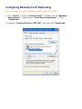
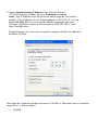
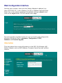
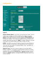
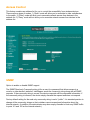
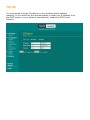
1
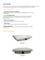
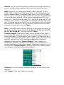
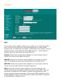
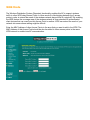
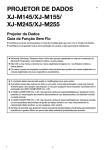
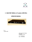
MiniLink
User Manual
802.11g Station Adapter/Access Point/LAN AP Bridge
FCC Information
This device complies with Part 15 of the FCC Rules. Operation is subject to the following two
conditions: (1) this device may not cause harmful interference, and (2) this device must accept any
interference received; including interference that may cause undesired operation.
Federal Communications Commission (FCC) Statement
This Equipment has been tested and found to comply with the limits for a Class B and C digital
device, pursuant to Part 15 of the FCC rules. These limits are designed to provide reasonable
protection against harmful interference in a residential installation. This equipment generates, uses
and can radiate radio frequency energy and, if not installed and used in accordance with the
instructions, may cause harmful interference to radio communications. However, there is no
guarantee that interference will not occur in a particular installation. If this equipment does cause
harmful interference to radio or television reception, which can be determined by turning the
equipment off and on, the user is encouraged to try to correct the interference by one or more of the following
measures:
- Reorient or relocate the receiving antenna.
- Increase the separation between the equipment and receiver.
- Connect the equipment into an outlet on a circuit different from that to which the receiver is
connected.
- Consult the dealer or an experienced radio/TV technician for help.
FCC RF Radiation Exposure Statement:
1. This Transmitter must not be co-located or operating in conjunction with any other antenna or
transmitter.
2. This equipment complies with FCC RF radiation exposure limits set forth for an uncontrolled
environment. This equipment should be installed and operated with a minimum distance of 20
centimeters between the radiator and your body.
Table of Contents
Disclaimers ………………………….………….….…….……….….………........4
Introduction ……………………………………………………………………….5
Before You Start ………………………………………………………………….6
Installation ………………………………………………………………..………. 7
Configuring Windows for IP Networking …………………………………….8
Web Configuration Interface …………………………………………………..10
Appendix A: Warranty Policy ……………………………………………...…..24
Appendix B: RMA Policy …………………………………………………...…..25
Appendix C: Regulatory Information ……………………………………...…26
Appendix D: Contact Information ………………………………………...…..28
Appendix E: Troubleshooting ………………………………………………...29
Appendix F: Glossary ……………………………………..……………………30
Disclaimers
No part of this documentation may be reproduced in any form or by any means or used to make any derivative work (such as
translation, transformation or adaptation) without written permission from the copyright owner.
All other trademarks and registered trademarks are the property of their respective owners.
Statement of Conditions
We may make improvements or changes in the product described in this documentation at any time. The information
regarding the product in this manual is subject to change without notice.
We assume no responsibility for errors contained herein or for direct, indirect, special, incidental or consequential damages
with the furnishing, performance or use of this manual or equipment supplied with it, even if the suppliers have been advised
about the possibility of such damages.
Electronic Emission Notices
This device complies with Part 15 of the FCC Rules. Operation is subject to the following two conditions:
(1)This device may not cause harmful interference.
(2)This device must accept any interference received, including interference that may cause undesired operation.
FCC INFORMATION
The Federal Communication Commission Radio Frequency Interference Statement includes the following paragraph:
The equipment has been tested and found to comply with the limits for a Class B Digital Device, pursuant to part 15 of the
FCC Rules. These limits are designed to provide reasonable protection against harmful interference in a residential
installation. This equipment usage generates radio frequency energy and, if not installed and used in accordance with the
instructions, may cause harmful interference to radio communication. However, there is no grantee that interference will not
occur in a particular installation. If this equipment does cause harmful interference to radio or television reception, which can
be determined by turning the equipment off and on, the user is encouraged to try to correct the interference by one or more of
the following measures:
•
Reorient or relocate the receiving antenna.
•
Increase the separation between the equipment and receiver.
•
Connect the equipment into an outlet on a circuit different from that to which the receiver is connected.
•
Consult the dealer or an experienced radio/TV technician for help.
The equipment is for home or office use.
IMPORTANT NOTE
FCC RF Radiation Exposure Statement: This equipment complies with FCC RF radiation exposure limits set forth for an
uncontrolled environment. This equipment should be installed and operated with a minimum distance of 20cm between the
antenna and your body and must not be co-located or operating in conjunction with any other antenna or transmitter.
Caution: Changes or modifications not expressly approved by the party responsible for compliance could
void the user's authority to operate the equipment.
Introduction
This Wireless 3-in-1 AP is quite a friendly device to have around, with dedicated one LAN/WAN port, it can be
communicated with other mobile devices for 802.11g standard-base wireless network connectivity.
Features and Benefits
High Speed & Backward Compatible
The high-speed wireless device simultaneously supports both IEEE802.11b/802.11g 54 Mbps
wireless networks.
3-in-1 AP operating mode
Three different functions are integrated as well: Access Point, Station and support WDS
(Wireless Distribution System), you could easily extend your Wireless LAN Network to
any where you want.
Multiple Client Support
Create a big wireless network to connect more hubs or switches.
WEB Interface
It is easy to configure the device or upgrade the Firmware via WEB browser.
Enhanced Security
Provides the highest available level of WEP / WAP-PSK as well as MAC Address Control to
increase security.
MiniLink Product Photos
Side View
Front View
Before You Start
System Requirements
•
•
•
•
Any desktop or laptop with an Ethernet interface
TCP/IP protocol suite installed
Standard CAT5 Ethernet cables with RJ45 connectors
Internet Explorer 5.0 or later / Firefox 1.0 or higher
Checklist
Product Kit Part Listing
1.
1.
2.
3.
4.
5.
6.
MiniLink Unit (1)
Power over Ethernet Injector (1)
24VDC Power Adapter (1)
Ethernet Cable (2)
Waterproof RJ-45 Connector (1)
Mounting Hardware (1)
User Manual
Note: If any item listed above is damaged or missing, please contact your dealer immediately.
Installation
Preparation for Installation
Always double check for any missing parts from the kit you received before deployment.
Next step is to set up the computer Ethernet interface for configuring the MiniLink. Since the default IP Address of the
unit is on the 192.168.0.x IP range in both Client Bridge and AP mode you’ll need to set the computer Ethernet
interface within the same IP range, where the x will have to be a free IP address number from 1-254.
Check the following section - “Hardware Installation” and the next chapter - “Configuring Windows for IP Networking” to
obtain complete details.
Hardware Installation
Follow the procedure below to install your MiniLink device:
1.
Select a suitable place on the network to install the MiniLink. For best wireless reception and performance the
external antenna should be positioned within Line of Sight from the AP with proper alignment.
2.
Connect the MiniLink to the ODU side of the PoE Injector, via a straight Ethernet cable (Cat-5), then connect the
NET side of the PoE Injector to either a computer or an Ethernet Switch.
3.
Connect the 24VDC power adapter to the power jack on the PoE injector to power on the MiniLink.
4.
Now the hardware installation is complete, and you may proceed to the next chapter –“Configuring Windows for
IP Networking” for instruction on setting up network configurations.
Configuring Windows for IP Networking
How to assign a static IP Address in Windows XP/2000?
1. Go to “Start” > Click on “Control Panel” > Double-click on “Network
Connections” > Right-click on “Local Area Connections” > Click
“Properties”
2. Highlight “Internet Protocol (TCP/IP)” and then click “Properties”.
3. Select Use the following IP address in the Internet Protocol
(TCP/IP) Properties window. Set your IP address and subnet
mask. (The IP Address must be within the same range as your station
adapter. The IP Address of your station adapter is 192.168.0.2. You can
assign 192.168.0.100 for your computer. No two computers can have
the same IP Address. Assign a subnet mask of (255.255.255.0.) and
then Click OK button.
Congratulations! You have now successfully assigned a Static IP Address in
Windows XP/2000.
Note: Again the IP address must be in the format of 192.168.0.x. Where the value of X should be
ranged from 1 to 254, excluding 2.
4. Click OK.
Web Configuration Interface
Activate your browser, then type this Station Adapter’s address (e.g.
http://192.168.0.2), in the Location (f or IE) or Address field and press
Enter. Key in the system password (the default setting is default ) and
click on the Login button. You will see the main page.
The main window provides 5 items for you to monitor and configure the
Wireless LAN Access Point: Information, Configuration, TCP/IP,
Statistics and Firmware Upgrade.
Information
This item shows the current information on the 802.11g Wireless LAN
Station Adapter such as MAC Address, Firmware Version as well as Boot
Version.
Configuration
General:
Station Adapter Name: In this field, you may enter any name. This will
enable you to manage your Station Adapter more easily if you have
multiple station adapters on the network. Besides, Station Adapter
Name can be used to prevent you from forgetting an IP Address and fail
to access the website. Try to type the nickname you like to identify the
website, then press the button of “Apply” to reboot. Whenever you want
to get back to the website again, just type the name you login.
ESSID: The ESSID is a unique ID used by Access Points and Stations to
identify a wireless LAN. Wireless clients associating to any Access Point
must have the same ESSID. The default ESSID is ANY. The ESSID can
have up to 32 characters.
Network Type: There are 2 network types for the wireless station
adapter to operate. If you need to access company network or Internet
via Access Point, select “Infrastructure”. To set up a group of wireless
stations for files and printer sharing, select “Ad-Hoc” (without Access
Point). For Ad-Hoc operation, the same ESSID is required to set for the
wireless stations.
Channel: Select a clear and available channel as an operational channel
for your wireless station adapter when it performs as Ad-Hoc mode.
Mode: There are three different wireless modes to operate, “B Only
Mode”, “G Only Mode”, and “B/G Mixed Mode”. In B/G Mixed Mode, the
wireless station adapter is compatible with a mix of both 802.11g and
802.11b clients. You will see that the factory-set default “B/G Mixed Mod”
will prove the most efficient. B Only Mode is compatible with 802.11b
clients only. This mode can be used only if you do not allow any 802.11g
clients to join a network. G Only Mode is compatible with 802.11g clients
only. This mode can be used only if you do not allow any 802.11b clients
to access to the network. To switch the mode, select the desired mode
form the pull-down menu next to “Mode”.
Rate: The wireless station adapter provides various data rate options for
you to choose. Data rates options include Auto, 1, 2, 5.5, 11, 6, 9, 12,
18, 24, 36, 48 and 54. The default setting is Auto.
Country/Region: Allows you to select country domain in case there is
any chances that you would use wireless network in other countries.
There are a total of 11 countries for you to select. They are Africa, Asia,
Australia, Canada, Europe, France, Israel, Japan, Mexico, South America,
and USA. Note that if your AP and station adapter are in different
standards, please use the “Country/Region” item to switch the
standards of the station adapter (For example, if your Access Point is
America standard but your station adapter is Japanese standard, you can
pull down the “Country/Region” option to switch your station adapter
from Japanese standard to American standard.).
Password: You may change the default password by entering the new
password.
Click “Apply” if you have made any changes.
SECURITY:
WEP:
The wireless station adapter allows you to create up to 4 data encryption
keys to secure your data from being eavesdropping by unauthorized
wireless user. To enable the encryption, all devices on the network, such as
the Access Point, must share the same WEP selection – either Enable or
Disable, and they must share the same WEP key.
Disable: Allows the wireless station adapter to communicate with the
Access Point without any data encryption.
WEP40: Requires the wireless station adapter to use data encryption
with 40-bit algorithm when communicating with the Access Point.
WEP128: Allows the wireless station adapter to communicate with the
Access Point with data 128-bit encryption algorithm.
WPA: Allows the wireless station adapter to communicate with the
Access Point with a more secure data protection than the WEP. Here you
can select the WPA with PSK mode to improve the data security and
privacy during wireless transmission. The present WPA supplied with this
station adapter is used in a pre-shared key mode, which does not require
an authentication (Radius) server.
For 40bit encryption you may choose:
ASCII: Enter 5 characters (case sensitive) ranging from “a-z”, “A-Z”
and “0-9” (e.g. MyKey).
Hex: Alternatively, you may enter 10 hexadecimal digits in the range
of “A-F”, “a-f” and “0-9” (e.g. 11AA22BB33).
For 128bit encryption you may choose:
ASCII: Enter 13 characters (case sensitive) ranging from “a-z”, “A-Z”
and “0-9” (e.g. MyKey12345678).
Hex: Alternatively, you may enter 26 hexadecimal digits in the range
of “A-F”, “a-f” and “0-9” (e.g. 00112233445566778899AABBCC).
After entering the WEP keys in the key field, select one key as active key.
Alternatively, you may create encryption keys automatically by using
Passphrase. From the Passphrase field, type a character string and click
Generate. As you type, the wireless station adapter will use an algorithm to
generate 4 keys automatically. Select one key from the 4 WEP keys.
Moreover, the wireless station adapter provides two types of authentication
services: Open System and Shared Key. The default authentication type is
Open System. If you require higher security for wireless access, you may
select Shared Key. Note that when Shared Key is selected, a WEP key is
required and must be the same with the key that Shared-Key-enabled AP
uses.
For WPA-PSK mode you may choose:
In the WPA-PSK field, you may enter 8-63 characters ranging from “a-z”,
“A-Z” and “0-9”.
WDS Mode
The Wireless Distribution System (Repeater) functionality enables this AP to support wireless
traffic to other WDS relay Access Points. In other words it is like bridging between the 2 access
points in order to extend the reach of the wireless network beyond that of a single AP. By enabling
the WDS feature the coverage area of the wireless network is thus extended for authenticated
client devices that can roam from this Access Point to another. WDS can extend the reach of your
network into areas where cabling might be difficult.
Enter the MAC Address of other Access Points in the area that you want to add to the WDS. The
MAC Address of this Access Point should be also be added to other access points in the same
WDS network to enable intra-AP communication.
Access Control
This feature contains an address list for you to control the accessibility from wireless devices.
There are three types of modes: 1) “Open” mode will allow you to associate to other units/devices
to the public. 2) “Allow” mode will allow you to associate network access from devices in the
address list. 3) “Deny” mode will not allow you to associate network access from devices in the
address list.
SNMP
Option to enable or disable SNMP support.
The SNMP Read-only Community string is like a user id or password that allows access to a
router's or other device's statistics. InterMapper sends the community string along with all SNMP
requests. If the community string is correct, the device responds with the requested information. If
the community string is incorrect, the device simply discards the request and does not respond.
Factory default setting for the read-only community string is set to "public". It is standard practice to
change all the community strings so that outsiders cannot access/read information about the
internal network. (In addition, the administrator may also employ firewalls to block any SNMP traffic
to ports 161 and 162 on the internal network.)
Parameter Log
This feature enables a user to save their current settings to their local hard drive of
their PC. This is primarily use for importing and exporting configurations/settings.
Advanced
RTS threshold
RTS Threshold is the frame size above which an RTS/CTS handshake will be performed
before attempting to transmit. RTS/CTS asks for permission to transmit to reduce
collisions but adds considerable overhead. Disabling RTS/CTS can reduce overhead
and latency in WLANs where all stations are close together but can increase collisions
and degrade performance in WLANs where stations are far apart and unable to sense
each other to avoid collisions (aka Hidden Nodes). If you are experiencing excessive
collisions you can try turning RTS/CTS on or (if already on) reduce RTS/CTS Threshold
on the affected stations.
Fragmentation threshold
Fragmentation Threshold is the maximum length of the frame beyond which payload
must be broken up (fragmented) into two or more frames. Collisions occur more often
for long frames because sending them occupies the channel for a longer period of
time, increasing the chance that another station will transmit and cause collision.
Reducing Fragmentation Threshold results in shorter frames that "busy" the channel
for shorter periods, reducing packet error rate and resulting retransmissions.
However, shorter frames also increase overhead, degrading maximum possible
throughput, so adjusting this parameter means striking a good balance between error
rate and throughput.
Beacon Period
In wireless networking, a beacon is a packet sent by a connected device to inform
other devices of its presence and readiness. When a wirelessly networked device
sends a beacon, it includes with it a beacon interval which specifies the period of time
before it will send the beacon again. The interval tells receiving devices on the
network how long they can wait in low-power mode before waking up to handle the
beacon. Network managers can adjust the beacon interval, usually measured in
milliseconds (ms) or its equivalent, kilo microseconds (Kμsec).
DTIM interval
A Delivery Traffic Indication Message (DTIM) is a signal sent as part of a beacon by an
access point to a client device in sleep mode, alerting the device to a packet awaiting
delivery. A DTIM interval, also known as a Data Beacon Rate, is the frequency at
which an access point's beacon will include a DTIM. This frequency is usually
measured in milliseconds (ms) or its equivalent, kilo microseconds (Kμsec).
TCP/IP
You may assign a proper IP address to your wireless station adapter
manually. If you would like the wireless station to obtain the IP address from
the DHCP server on your network automatically, enable the DHCP client
function.
Statistics
General:
This item allows you to monitor the general information of the Access Point
with which your wireless station is communicating such as Link Status,
ESSID, BSSID, Channel, Signal as well as RX/TX from Ethernet packets.
AP Browser:
By clicking the “Refresh” button, the AP Browser will reload and display
the available Access Points around the working environment. Besides
showing the BSSID of each Access Point, it also displays ESSID, Channel,
Support Rate and Capability.
Firmware Upgrade
Here, you can upload the latest firmware of the wireless station adapter.
You may either enter the file name in the entry field or browse the file by
clicking the “Browse” button. Then click the “Apply” button to begin to
upgrade the process.
Appendix A: Warranty Policy
Limited Warranty
All Teletronics’ products warranted to the original purchaser to be free from defects in materials and workmanship
under normal installation, use, and service for a period of one (1) year from the date of purchase.
Under this warranty, Teletronics International, Inc. shall repair or replace (at its option), during the warranty period, any
part that proves to be defective in material of workmanship under normal installation, use and service, provided the
product is returned to Teletronics International, Inc., or to one of its distributors with transportation charges prepaid.
Returned products must include a copy of the purchase receipt. In the absence of a purchase receipt, the warranty
period shall be one (1) year from the date of manufacture.
This warranty shall be voided if the product is damaged as a result of defacement, misuse, abuse, neglect, accident,
destruction or alteration of the serial number, improper electrical voltages or currents, repair, alteration or maintenance
by any person or party other than a Teletronics International, Inc. employee or authorized service facility, or any use in
violation of instructions furnished by Teletronics International, Inc.
This warranty is also rendered invalid if this product is removed from the country in which it was purchased, if it is used
in a country in which it is not registered for use, or if it is used in a country for which it was not designed. Due to
variations in communications laws, this product may be illegal for use in some countries. Teletronics International, Inc.
assumes no responsibility for damages or penalties incurred resulting from the use of this product in a manner or
location other than that for which it is intended.
IN NO EVENT SHALL TELETRONICS INTERNATIONAL, INC. BE LIABLE FOR ANY SPECIAL, INCIDENTAL OR
CONSEQUENTIAL DAMAGES FOR BREACH OF THIS OR ANY OTHER WARRANTY, EXPRESSED OR IMPLIED,
WHATSOEVER.
Some states do not allow the exclusion or limitation of special, incidental or consequential damages, so the above
exclusion or limitation may not apply to you.
This warranty gives you specific legal rights, and you may also have other rights that vary from state to state.
Appendix B: RMA Policy
Product Return Policy
It is important to us that all Teletronics’ products are bought with full confidence. If you are not 100% satisfied with any
product purchased from Teletronics you may receive a prompt replacement or refund, subject to the terms and
conditions outlined below.
IMPORTANT: Before returning any item for credit or under warranty repair, you must obtain a Return Merchandise
Authorization (RMA) number by filling out the RMA form. Products will not be accepted without an RMA number. All
products being shipped to Teletronics for repair / refund / exchange must be freight prepaid (customer pays for
shipping). For all under warranty repair/replacement, Teletronics standard warranty applies.
30-Day full refund or credit policy:
1. Product was purchased from Teletronics no more than 30 day prior to the return request.
2. All shipping charges associated with returned items are non-refundable.
3. Products are returned in their original condition along with any associated packaging, accessories, mounting
hardware and manuals. Any discrepancy could result in a delay or partial forfeiture of your credit.
Unfortunately Teletronics cannot issue credits for:
1. Products not purchased from Teletronics directly. If you purchased from a reseller or distributor you must contact
them directly for return instructions.
2. Damaged items as a result of misuse, neglect, or improper environmental conditions.
3. Products purchased direct from Teletronics more than 30 days prior to a product return request.
To return any product under 1 year warranty for repair/replacement, follow the RMA procedure.
Appendix C: Regulatory Information
Statement of Conditions
We may make improvements or changes in the product described in this documentation at any time. The information
regarding to the product in this manual are subject to change without notice.
We assume no responsibility for errors contained herein or for direct, indirect, special, incidental, or consequential
damages with the furnishing, performance, or use of this manual or equipment supplied with it, even if the suppliers
have been advised of the possibility of such damages.
Electronic Emission Notices
This device complies with Part 15 of the FCC Rules. Operation is subject to the following two conditions:
(1) This device may not cause harmful interference.
(2) This device must accept any interference received, including interference that may cause undesired operation.
FCC Information
The Federal Communication Commission Radio Frequency Interference Statement includes the following paragraph:
The equipment has been tested and found to comply with the limits for a Class B Digital Device, pursuant to part 15 of
the FCC Rules. These limits are designed to provide reasonable protection against harmful interference in a residential
installation. This equipment generates, uses and can radiate radio frequency energy and, if not installed and used in
accordance with the instruction, may cause harmful interference to radio communication. However, there is no
guarantee that interference will not occur in a particular installation. If this equipment does cause harmful interference
to radio or television reception, which can be determined by turning the equipment off and on, the user is encouraged
to try to overcome the interference by one or more of the following measures:
-
Reorient or relocate the receiving antenna.
Increase the separation between the equipment and receiver.
Connect the equipment into an outlet on a circuit different from that to which the receiver is connected.
Consult the dealer or an experienced radio/TV technician for help.
The equipment is for home or office use.
Important Note
FCC RF Radiation Exposure Statement: This equipment complies with FCC RF radiation exposure limits set forth for
an uncontrolled environment. This equipment should be installed and operated with a minimum distance of 20cm
between the antenna and your body and must not be co-located or operating in conjunction with any other antenna or
transmitter.
Caution: Changes or modifications not expressly approved by the party responsible for compliance could void the
user's authority to operate the equipment.
R&TTE Compliance Statement
This equipment complies with all the requirements of the Directive 1999/5/EC of the European Parliament and the
Council of 9 March 1999 on radio equipment and telecommunication terminal equipment (R&TTE)and the mutual
recognition of their conformity. The R&TTE Directive repeals and replaces in the directive 98/13/EEC. As of April 8,
2000.
European Union CE Marking and Compliance Notices
Products intended for sale within the European Union are marked, which indicates compliance with the applicable
directives identified below. This equipment also carries the Class 2 identifier.
With the Conformité Européene (CE) and European standards and amendments, we declare that the equipment
described in this document is in conformance with the essential requirements of the European Council Directives,
standards, and other normative documents listed below:
73/23/EEC Safety of the User (article 3.1.a)
89/336/EEC Electromagnetic Compatibility (article 3.1.b)
1999/5/EC (R&TTE) Radio and Telecommunications Terminal Equipment Directive.
EN 60950 2000 Safety of Information Technology Equipment, Including Electrical Business Equipment.
EN 300 328 V1.4.1(2003) Electromagnetic compatibility and Radio spectrum Matters (ERM); Wideband Transmission
systems;Data transmission equipment operating in the 2,4 GHz ISM band and using spread spectrum modulation
techniques;Harmonized EN covering essential requirements under article 3.2 of the R&TTE Directive.
EN 301 489-1, V1.4.1(2002); EN 301 489-17, V1.2.1(2002) – Electromagnetic compatibility and radio spectrum
matters (ERM); electromagnetic compatibility (EMC) standard for radio equipment and services: Part 1: Common
technical requirements; Part 17: Part 17: Specific conditions for 2,4 GHz wideband transmission systems and5 GHz
high performance RLAN equipment
Warning: According to ERC/REC 70-30 appendix 3 National Restrictions, annex 3 Band A “RLANs and HIPERLANs.”
See list of 802.11b/g restrictions for specific countries under the heading “European Economic Area Restrictions” as
below.
English
This product follows the provisions of the European Directive 1999/5/EC.
Danish
Dette produkt er i overensstemmelse med det europæiske direktiv 1999/5/EF
Dutch
Dit product is in navolging van de bepalingen van Europees Directief 1999/5/EC.
Finnish
Tämä tuote noudattaa EU-direktiivin 1999/5/EY määräyksiä.
French
Ce produit est conforme aux exigences de la Directive Européenne 1999/5/CE.
Appendix D: Contact Information
Need to contact Teletronics?
Visit us online for information on the latest products and updates to your existing products at:
http://www.teletronics.com
Can't find information about a product you want to buy on the web? Do you want to know more about networking with
Teletronics products?
Give us a call at: 301-309-8500 Or fax your request in to: 301-309-8551
Don't wish to call? You can e-mail us at: [email protected]
If any Teletronics product proves defective during its warranty period, you can email the Teletronics Return
Merchandise Authorization department to obtain a Return Authorization Number at: [email protected]
(Details on Warranty and RMA issues can be found in Appendix A and B)
Appendix E: Troubleshooting
Symptom: Can not access the MiniLink through the web browser
Resolution:
•
•
•
•
•
Check that the IP address in the URL field is correct.
Check your host computer IP address. If the IP address of the MiniLink is 192.168.0.2 then the host computer
IP must set to the 192.168.0.X subnet.
If using the PoE make sure that you’re using the provided 24V power adapter. Make sure that the MiniLink is
connected to the ODU side of the PoE. The computer should be connected to the NET side of the PoE.
Clear out all internet cache and cookies.
Clear the ARP table by going into the dos prompt and type in the following: arp –d
Symptom: The web control interface graphics isn’t showing up properly
Resolution:
Due to many anti-malware software on the market some features of these programs may disable certain IE functions
which can then lead to pictures not being displayed correctly. If this happens try turning off some of the more restrictive
features of these anti-malware software or try accessing the web control interface with a different browser such as the
firefox.
Symptom: Cannot connect to the MiniLink with a wireless client
Resolution:
•
•
•
•
•
•
•
Make sure that the client supports the wireless mode that the MiniLink is set to.
Make sure that the Mode, SSID (Cap Sensitive), Channel and encryption settings are set the same on both
sides.
Make sure that your computer is within range and free from any strong electrical devices that may cause
interference.
Double check that the wireless client is set to the appropriate transmission speed under the advanced tab of
the wireless connection property.
Temporary disable all securities and encryption settings.
Try it on a different client.
If DHCP is enabled make sure that the client is set to obtain an IP automatically.
Appendix F: Glossary
802.1x - The standard for wireless LAN authentication used between an AP and a client. 802.1x with EAP will initiate
key handling.
Ad-Hoc Network - The wireless network based on a peer-to-peer communications session. Also referred to as AdHoc.
Access Point - Access points are stations in a wireless LAN that are connected to an Ethernet hub or server. Users
can roam within the range of access points and their wireless device connections are passed from one access point to
the next.
Authentication - Authentication refers to the verification of a transmitted message's integrity.
Beacon - In wireless networking, a beacon is a packet sent by a connected device to inform other devices of its
presence and readiness.
Beacon interval - When a wirelessly networked device sends a beacon, it includes with it a beacon interval, which
specifies the period of time before it will send the beacon again. The interval tells receiving devices on the network
how long they can wait in low-power mode before waking up to handle the beacon. Network managers can adjust the
beacon interval, usually measured in milliseconds (ms) or its equivalent, kilo microseconds (Kmsec).
BSS - Basic Service Set. When a WLAN is operating in infrastructure mode, each access point and its connected
devices are called the Basic Service Set.
BSSID - The unique identifier for an access point in a BSS network. See SSID for more details.
DHCP - DHCP (Dynamic Host Configuration Protocol) software automatically assigns IP addresses to client stations
logging onto a TCP/IP network, which eliminates the need to manually assign permanent IP addresses.
DSSS (Direct Sequence Spread Spectrum) - Method of spreading a wireless signal into wide frequency bandwidth.
Dynamic IP Address - An IP address that is automatically assigned to a client station in a TCP/IP network, typically by
a DHCP server.
DNS (Domain Name System): System used to map readable machine names into IP addresses
DTIM - DTIM (Delivery Traffic Indication Message) provides client stations with information on the next opportunity to
monitor for broadcast or multicast messages.
DTIM interval - A DTIM interval, also known as a Data Beacon Rate, is the frequency at which an access point's
beacon will include a DTIM. This frequency is usually measured in milliseconds (ms) or its equivalent, kilo
microseconds (Kmsec).
ESS - Extended Service Set. ESS is the collective term for two or more BSSs that use the same switch in a LAN.
ESSID - Extended Service Set Identifier. An ESSID is the unique identifier for an ESS. See SSID for more details.
Filter - Filters are schemes, which only allow specified data to be transmitted. For example, the router can filter
specific IP addresses so that users cannot connect to those addresses.
Firmware: Programming inserted into programmable read-only memory, thus becoming a permanent part of a
computing device.
Fragmentation - Refers to the breaking up of data packets during transmission.
Gateway – Is the place where two or more networks connect
IBSS - Independent Basic Service Set. See ad-hoc network
Infrastructure Mode - When a wireless network functions in infrastructure mode, every user communicates with the
network and other users through an access point; this is the typical way corporate WLANs work. An alternative is adhoc mode, but users would have to switch to infrastructure mode to access a network's printers and servers.
ISP - An ISP is an organization providing Internet access service via modems, ISDN (Integrated Services Digital
Network), and private lines.
LAN(Local Area Network): A group of computers and peripheral devices connected to share resources.
MAC (Medium Access Control) Address: A unique number that distinguishes network cards.
MTU - MTU (Maximum Transmission/Transfer Unit) is the largest packet size that can be sent over a network.
Messages larger than the MTU are divided into smaller packets.
NAT - NAT (Network Address Translation - also known as IP masquerading) enables an organization to present itself to
the Internet with one address. NAT converts the address of each LAN node into one IP address for the Internet (and
vice versa). NAT also provides a certain amount of security by acting as a firewall by keeping individual IP addresses
hidden from the WAN.
Preamble - Preamble refers to the length of a CRC (Cyclic Redundancy Check) block that monitors’ communications
between roaming wireless enabled devices and access points.
Protocol - A standard way of exchanging information between computers.
RADIUS (Remote Authentication Dial In User Service): A server that issues authentication key to clients.
RAM (Random Access Memory): Non-permanent memory.
RIP - RIP (Routing Information Protocol) is a routing protocol that is integrated in the TCP/IP protocol. RIP finds a route
that is based on the smallest number of hops between the source of a packet and its destination.
Router - A router is a device that forwards data packets along networks. The device is connected to at least two
networks, commonly two LANs or WANs or a LAN and an ISP. Routers are located at gateways, the places where two
or more networks connect and use headers and forwarding tables to determine the best path for forwarding the
packets. And they use protocols such as ICMP to communicate with each other and configure the best route between
any two hosts. Very little filtering of data is done through routers.
Roaming - The ability to use a wireless device while moving from one access point to another without losing the
connection.
RTS - RTS (Request To Send) is a signal sent from the transmitting station to the receiving station requesting
permission to transmit data.
Server - Servers are typically powerful and fast machines that store programs and data. The programs and data are
shared by client machines (workstations) on the network.
Static IP Address - A permanent IP address is assigned to a node in a TCP/IP network. Also known as global IP.
Subnet Mask - Subnet Masks (SUBNET work masks) are used by IP protocol to direct messages into a specified
network segment (i.e., subnet). A subnet mask is stored in the client machine, server or router and is compared with an
incoming IP ad-dress to determine whether to accept or reject the packet.
SSID - SSID (Service Set Identifier) is a security measure used in WLANs. The SSID is a unique identifier attached to
packets sent over WLANs. This identifier emulates a password when a wireless device attempts communication on the
WLAN. Because an SSID distinguishes WLANS from each other, access points and wireless devices trying to connect
to a WLAN must use the same SSID.
TCP/IP - TCP/IP (Transmission Control Protocol/Internet Protocol) is the main Internet communications protocol. The
TCP part ensures that data is completely sent and received at the other end. Another part of the TCP/IP protocol set is
UDP, which is used to send data when accuracy and guaranteed packet delivery are not as important (for example, in
real-time video and audio transmission).
TFTP (Trivial File Transfer Protocol) - Simple form of FTP (File Transfer Protocol), which Uses UDP (User Datagram
Protocol), rather than TCP/IP for data transport and provides no security features.
TKIP (Temporal Key Integrity Protocol): An encryption method replacing WEP.TKIP uses random IV and frequent key
exchanges.
UDP (User Datagram Protocol) - A communication method (protocol) that offers a limited amount of service when
messages are exchanged between computers in a network. UDP is used as an alternative
to TCP/IP.
Uplink: Link to the next level up in a communication hierarchy.
UTP (Unshielded Twisted Pair) cable - Two or more unshielded wires twisted together to form a cable.
Virtual Servers - Virtual servers are client servers (such as Web servers) that share resources with other virtual
servers (i.e., it is not a dedicated server).
WEP (Wired Equivalent Privacy) - An encryption method based on 64 or 128bit algorithm.
WLAN - WLANs (Wireless LANs) are local area networks that use wireless communications for transmitting data.
Transmissions are usually in the 2.4 GHz band. WLAN devices do not need to be lined up for communications like
infrared devices. WLAN devices use access points, which are connected to the wired LAN and provide connectivity to
the LAN. The radio frequency of WLAN devices is strong enough to be transmitted through non-metal walls and
objects, and can cover an area up to a thousand feet. Laptops and notebooks use wireless LAN PCMCIA cards while
PCs use plug-in cards to access the WLAN.