1
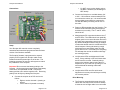
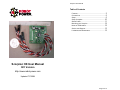
Scorpion User Manual
Table of Contents
Features ........................................................ 3
Connections ................................................... 5
Setup ............................................................ 5
Setup Complete ............................................ 10
Status Codes ................................................ 11
Mounting your Scorpion .................................. 12
Notes on PCM radios ...................................... 12
Service and Support ....................................... 13
Limitations and Warrantees .............................. 13
Scorpion HX User Manual
R/C Version
http://www.robot.power.com
Updated 7/7/2004
Page 2 of 13
Scorpion User Manual
Scorpion User Manual
Thank you for purchasing the Robot Power Scorpion HX
speed control. This unit has been carefully engineered
and tested to provide superior performance and control
of small robots. This document covers the features and
operation of the Scorpion commanded via R/C control.
A serial command firmware version is under
development to allow control of the Scorpion via TTLlevel serial commands. Contact Robot Power for details
on this and other special versions of the Scorpion.
The Scorpion HX controller was designed for use in 1 lb.
(ant weight) and 3 lb. (beetle weight) combat robots: but
it is suitable for a variety of small mobile robots such as
sumo, firefighting, and maze runner types.
•
Flip input reverses motor direction when the
robot is inverted. May be operated via an R/C
channel or via a mechanical (gravity) or optical
etc. switch.
•
Indicator LEDs for Left/Right speed and
direction and Aux speed. A status LED shows
the R/C signal status and other information (see
below)
•
Left/Right channel mixing is the default – may
be disabled
•
Drive mirroring causes both motor outputs to
“mirror” a single RC input channel if only one is
connected. This allows the use of a single
larger motor per Scorpion or a slaved pair of
motors. Thus, two Scorpions can be used with
mirroring to drive a dual 5A motor robot or a 4motor robot without needing R/C splitter cables.
•
Receiver battery eliminator circuit (BEC)
standard – may be disabled. This can provide
up to 100 mA of current at 5V to the RC receiver
and other attached electronic circuits. Do not
attempt to run servos or other motors using the
Scorpion regulator as the current source. Doing
so may damage the regulator and cause the
Scorpion to cease working.
•
Safe start for Aux channel disables the robot at
power up until the Aux channel is in the off
position.
•
Failsafe shuts off motors and weapon if R/C
signal is lost
•
FLASH-based microcontroller with upgradeable
software via in-circuit programming header
Features
The Scorpion contains the following features:
•
Size: 1.6” x 1.6” x .5”
•
Weight: 22g with RC cables installed
•
Four R/C input leads for
o Left and Right Drive
o Auxiliary Weapon - forward only
(optional)
o Flip Control (optional)
•
4.8V to 22V battery voltage
•
6A peak, 2.5A (5A with heatsink) continuous
current on each Left and Right drive channels.
May be combined into a single 5A continuous
forward/reverse channel
•
35A peak, 12A continuous current on the
Aux/Weapon channel. This can be used to
drive a forward-only motor such as a spinning
weapon or sumo vacuum system. Note, the
12A figure must be derated for power settings
less than 100%.
Page 3 of 13
Page 4 of 13
Scorpion User Manual
Scorpion User Manual
Connections
o
Do NOT use a receiver battery unless
the BEC is disabled (see Disabling the
BEC below)
Connect the Scorpion to a suitable battery (6V
to 22V – 18V maximum recommended) but do
not connect the motors yet. It is recommended
that a suitable power switch be connected inline with the battery for testing and for use on
the robot.
Power on RC transmitter then the Scorpion. The
Status LED should flash rapidly several times
and then turn on solidly. The LT and RT LEDs
should be off.
Setup
Your Scorpion HX controller comes completely
assembled and tested and programmed with the latest
version of the firmware available.
The Scorpion firmware is programmed to respond
properly to R/C signals from all major radio control
brands and should operate right out of the box. The
following procedure will set your radio system to match
the parameters of the Scorpion.
Important! Do not reverse the battery polarity to the
Scorpion. On the green screw terminal block the battery
connections are marked B+ and B-. Connect the
battery positive to B+ and the negative to B-. Reversing
polarity even briefly may damage the Scorpion.
Connect the scorpion to an R/C receiver as
follows
o Right to receiver channel 1 (steering or
aileron)
o Left to channel 2 (throttle or elevator)
Page 5 of 13
Manipulate the RC controls and observe the LT
and RT LEDs. The LEDs should turn gradually
brighter green in one control direction and red in
the other as the transmitter controls are moved.
By default Left/Right channel mixing is enabled
so when the throttle control is moved both LEDs
should respond. Moving the steering control
with throttle at neutral should make one LED
green and one red. If necessary turn everything
off and swap the receiver channels until things
are working properly.
Verify that the LEDs are brightest at full stick
travel. If they suddenly cut off at full throw then
the RC travel is too wide. Gradually reduce
throw on the problem channel using the ATV
adjustment on your radio until you can go to full
travel with both the steering and throttle
controls.
Verify that the LEDs are off at stick center.
Adjust the trim center point until they are solidly
off at center position.
Drive Mirroring
The Scorpion automatically detects which R/C
cables are connected to the receiver at startup.
If either the Left or Right cable is not connected
Page 6 of 13
Scorpion User Manual
Scorpion User Manual
to the receiver the Scorpion goes into drive
Mirror Mode. In this mode the signal from either
the Left or Right input is mirrored to both of the
output channels. This is designed to allow easy
use of two Scorpions with 4 motors without
requiring R/C “Y” cables to the receiver.
Transmitter mixing must be used when using
Mirror Mode.
Connect either the Left or Right input connector
to the R/C receiver and leave the other
unconnected.
Turn on the transmitter then the Scorpion and
observe that both output channels respond to
the single input channel.
For added resistance to electrical interference in
the unused cable, connect the signal wire
(yellow or white) to the ground wire (brown or
black) with a short jumper wire. This will ensure
that no noise can be seen as a valid R/C signal
on that cable.
Flip Control Not Used
Important! If you are not using the Flip control
you should tie the yellow or white signal wire of
the Flip R/C cable to the red center (+5V) wire
to prevent any interference from inadvertently
tripping the Flip function. You can either place a
small jumper wire in the end of the R/C
connector or clip off the Flip cable near the
Scorpion board and solder the two wires
together.
respond as before. If there is no response on
the drive channels verify that the Flip RC cable
is properly inserted into the receiver. If the
problem persists it is likely that the throw on the
Flip channel is too wide. Reduce this travel
using the ATV adjustment until the drive begins
to work again. Be sure to reduce the ATV on
both ends of the throw and verify that the drive
channels work with the Flip control in both
positions.
Activate the transmitter Flip channel and verify
that the controls are reverse. This is easy to
see if you activate the flip control while the drive
channels are active and see that the LEDs
change color when the Flip control is activated.
Mechanical Flip Control
If you are using a gravity switch to activate the
Flip control you will need to connect a normally
open switch to the Flip RC lead. Use care to
avoid shorting the center (+5V) and outer
(ground) wires on the RC lead together. This
can damage the Scorpion.
One switch contact should connect to the black
(or brown) wire closest to the edge of the board
- this is the ground wire. The other should
connect to the white or yellow wire closest to the
center of the board – this is the signal wire. The
center wire is available to provide +5V if an
optical or other electronic switch is used. When
the switch is closed the signal wire will be
connected to the ground wire and provide a 0V
signal level on the signal wire.
RC Flip Control
If you are using the RC Flip function then turn
everything off and connect the Flip RC lead to
the appropriate receiver channel. Channel 5
(landing gear) is commonly used on aircraft
receivers and channel 3 on pistol style car
radios. Power on the RC transmitter and then
the Scorpion. Verify that the drive channels
Page 7 of 13
If an optical or other electronic switch is used,
the normal signal level is +5V on the signal wire
for normal operation and 0V for flipped
operation.
Verify that the drive channels operate properly
with the switch in both positions. If not,
disconnect the Flip switch and carefully look for
Page 8 of 13
Scorpion User Manual
Scorpion User Manual
shorts and verify with a multimeter that the
switch is pulling the signal wire to ground when
closed.
should be reduced via the ATV control on your
transmitter. Gradually reduce the top end travel
point until the Aux LED lights up with full
brightness.
Auxiliary Weapon Control (optional)
If you are using the Aux control to drive a
weapon or vacuum motor it is important to
understand that this is a forward only control.
There is no reverse on this channel. The speed
increases proportionally from off at center stick
position to 100% at full throw. This allows PCM
radios (that output a center stick position signal
in a fail-safe condition) to properly shut off the
Aux output if the signal is lost. The brightness
of the Aux LED indicates the relative power
applied to that motor.
Turn everything off and connect the Aux RC
input lead to the appropriate receiver channel.
The throttle channel (3) is commonly used here
for proportional speed or channel 5 may be
used for on-off control.
For safety the Aux channel must be in the off
position before the robot will activate either the
weapon or drive. If the Scorpion is powered on
with the Aux control in a non-zero location the
Scorpion will wait until the Aux is safe before
allowing the robot to move. A blinking status
code will signal that the Scorpion is waiting for a
safe start position on the Aux channel.
Turn on the transmitter and observe the Status
LED. It should blink rapidly several times and
then either begin a slow blink or go solid. If the
Status LED is blinking move the Aux control to
the off position. The Status LED should go solid
and the drive and Aux channels should respond.
Once the Status LED is solid you should be able
to advance the Aux RC control and see the Aux
LED increase in brightness all the way up to full
travel. If the Aux LED suddenly cuts out near
full control throw the RC travel is too wide and
Page 9 of 13
If the Scorpion refuses to respond when the Aux
channel is in the extreme off position it means
the RC travel is too wide in that direction.
Reduce the low-end throw on that channel using
the ATV adjustment until the drive works
normally at all Aux control positions.
Setting Tank Steering
The Scorpion comes with Left/Right channel mixing
on by default. To disable this mixing a jumper
should be soldered into the holes where indicated in
the Connections photo above. When the jumper is
in place the Left and Right inputs will each control
one motor independently from the other. This is
useful for tank steering in certain robots or where
transmitter mixing is preferred. Note, the photo
shows a pin header in these holes. Production
Scorpions do not have this header installed and
instead have empty holes at this location.
Disabling the BEC
The Scorpion comes with a 5V regulator to run its
microprocessor and other logic circuits. This 5V is
available to power the RC receiver and “eliminates”
the need for a separate RC receiver battery. To
disable this function locate the two pads marked
BEC near the RC cables. There are two bare pads
connected by a short trace. To disable the BEC
function carefully cut this trace with a sharp knife.
Make sure to completely cut the trace and leave a
visible space between the cut conductors. To
restore the BEC simply solder a small wire across
the two pads.
Setup Complete
That completes the setup of your Scorpion board
and your RC transmitter. Connect the motors to the
Page 10 of 13
Scorpion User Manual
Scorpion User Manual
screw terminal block and verify that the motors
respond smoothly and properly to commands.
If the motors glitch or have large variations in speed
with a constant command input it is possible there is
interference being generated and coupled into the
Scorpion or the RC receiver. A small 0.1 uF
ceramic capacitor across the motor leads is
recommended to reduce this electronic noise. In
extreme cases three capacitors should be used; one
from each motor terminal to the motor case and one
across the terminals.
Also, if high current draw motors are used it is
possible the drive chips will overheat and go into
safety shut down. If your motors are cutting out
after a period of normal operation, feel the power
chips mounted on the bottom of the Scorpion. If
they are painfully hot to the touch then it is likely you
are exceeding the ratings of the chips. For reliable
operation you should reduce the battery voltage
and/or use smaller motors. For sustained operation
near the maximum current you may add a heatsink
to the bottom of the board to help with heat
dissipation. Commonly available Celeron/Pentium
CPU heatsinks with insulated adhesive tape on the
back are available at low cost from surplus and
computer dealers. You can press these onto the
drive chips to help greatly with heat dissipation at
the expense of additional weight and space.
Status Codes
•
•
Slow Blink – at startup this indicates that the
Aux channel is not in the safe position.
Mounting your Scorpion
The Scorpion should be mounted properly for the most
reliable operation. For use in combat robots shock
mounting is important. Do not simply bolt the Scorpion
down to the frame of your robot. The mounting holes
provided at the corners of the Scorpion should be large
enough for a rubber grommet and 4-40 mounting
screws. Placing the rubber grommet in the holes with
washers and nuts to suspend the Scorpion by the
rubber will provide adequate shock mounting.
Alternately using foam rubber servo tape or “mouse
pad” rubber can provide a secure shock mounting. If a
heat sink is desired to increase the current handling of
the board a flat plate should be pressed tightly against
the metal tabs of the power driver chips located on the
bottom side of the Scorpion. These tabs are electrically
connected to the battery ground so care should be take
to avoid shorts. Using a small amount of heat sink
compound a.k.a. thermal grease will help heat transfer
to the heat sink.
Notes on PCM radios
The Status LED is the main means of communicating
information on the state of the Scorpion board. The
following are the status codes seen under various
conditions:
•
startup. At startup a fast blink signal indicates
the transmitter is off or that the receiver is not
getting a signal.
Steady On – this indicates normal operation and
should be see at all time the Scorpion is
operating properly.
Fast Blink – this indicates a loss of radio signal
or no signal on any of the drive channels at
Page 11 of 13
The Scorpion will work properly with AM, FM and PCM
radios at all common pulse update rates (50 Hz in the
US, 40 Hz in the UK and elsewhere). However there
are several issues related to failsafe operation in PCM
radios that must be understood for reliable and safe
operation.
First, if possible, the fail-safe function on the radio
should be disabled for all channels controlled by the
Scorpion. This will allow the signal lost and out of range
functions in the Scorpion software to function properly.
If fail-safe cannot be disabled completely it should be
Page 12 of 13
Scorpion User Manual
set to move the control to a fixed position rather than
“last command hold”. In this way setting the drive
channels to 50% and the Aux channel to 50% (usually
the default) will cause the motors to shut off if the
transmitter signal is lost.
Note, the default settings hard-coded into the RC
receiver may not match the desired settings for proper
shutdown of the Scorpion. Testing with your radio will
be required for the proper settings and procedures to
be determined.
Service and Support
Service and support for the Scorpion are available
from Robot Power. The Robot Power Web site
(http://www.robot-power.com/) maintains current
contact information for all Robot Power products.
Limitations and Warrantees
The Scorpion is intended for personal experimental
and amusement use and in no case should be used
where the health or safety of persons may depend on
its proper operation. Robot Power provides no
warrantee of suitability or performance for any
purpose for the Scorpion. Use of the Scorpion
software and or hardware is with the understanding
that any outcome whatsoever is at the users own risk.
Robot Power’s sole guarantee is that the software and
hardware perform in compliance with this document at
the time it was shipped to the best of our ability given
reasonable care in manufacture and testing.
Products that have been used in robot combat
competitions or other competition situations are not
eligible for defective replacement. All claims for
defective product repair or replacement must be made
prior to the competitive use of the product. In the
event of a defective product, Robot Power will replace
or repair products or refund money in exchange for
the original product. Robot Power products
purchased through resellers or dealers must contact
the dealer for repair or replacement service.
Page 13 of 13