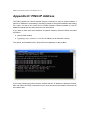
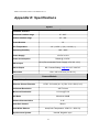
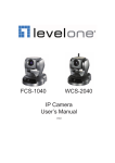
1
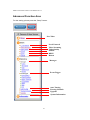
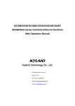
3G MPEG-4 Pan/Tilt
Network Camera
User Manual
Ver.0.2
MCAS-400PTG
MPEG-4 Network Camera User Manual Ver.0.2
PT Network Camera
Caution:
To avoid risk of fire or shock hazard, do not expose the unit to rain, liquid,
water, or extreme humidity.
To avoid risk of electrical shock, do not the cabinet of AC Adapter. Refer
service to authorized personnel only.
For consumers in the United States
This equipment has been tested and found to comply with the limits for a digital device,
pursuant to Part 15 of the FCC Rules. These limits are designed to provide reasonable
protection against harmful interference in a residential installation. This equipment generates,
uses, and can radiate radio frequency energy and, if not installed and used in accordance
with the instructions, may cause harmful interference to radio communications. However,
there is no guarantee that interference will not occur in a particular installation. If this
equipment does cause harmful interference to radio or television reception, which can be
determined by turning the equipment off and on, the user is encouraged to try to correct the
interference by one or more of the following measures:
1. Reorient or relocate the receiving antenna.
2. Increase the separation between the equipment and receiver.
3. Connect the equipment into an outlet on a circuit different from that to which the receiver
is connected.
4. Consult the dealer or an experienced radio/TV technician for help.
Defects or damages resulting from improper service, testing, adjustment, installation,
maintenance, alternation or modification by unauthorized service personnel are excluded
from coverage
The shielded interface cable recommended in this manual must be used with this
equipment in order to comply with the limits for a digital device pursuant to Part 15 of FCC
Rules.
Declaration of Conformity
This device complies with part 15 of the FCC Rules. Operation is subject to the following two
conditions:
1. This device may not cause harmful interference.
2. This device must accept any interference received, including interference that may cause
undesired operation.
2
MPEG-4 Network Camera User Manual Ver.0.2
Table of Contents
Overview............................................................................................................................. 4
Package Contents ................................................................................................................ 6
Connections......................................................................................................................... 9
Hardware Installation........................................................................................................ 11
Online Setups .................................................................................................................... 13
Before Operation....................................................................................................... 13
Access the Network Camera from the Internet Explorer.......................................... 15
Operating the Network Camera ........................................................................................ 18
Control Panel Area.................................................................................................... 19
Advanced Function Area........................................................................................... 21
Appendix A: Restore Factory Default Settings ................................................................. 45
Appendix B: Alarm I/O Connector ................................................................................... 46
Appendix C: Troubleshooting & Frequently Asked Questions ......................................... 48
Appendix D: PING IP Address ......................................................................................... 52
Appendix E: Specifications ............................................................................................... 53
Appendix F: Time Zone Table ........................................................................................... 55
Appendix G: DDNS Application ....................................................................................... 57
Appendix H: SMS Application .......................................................................................... 62
Appendix I: Adjust the Lens .............................................................................................. 65
Table A: Recording Disk Space......................................................................................... 66
3
MPEG-4 Network Camera User Manual Ver.0.2
Overview
This user’s guide is generated in PDF file which helps consumer go though installation
processes on the computer monitor. However consumers can also print out manual for
easier access during installation. Always contact your service provider about feature
availability and functionality. All features, functionality, and other product specifications,
as well as the information contained in this user’s guide are based upon the latest
available information and are believed to be accurate at the time of creating.
Introduction
Network Camera is an inexpensive fully scalable surveillance technology. Because the
Network Cameras can be plugged in to your existing computer network infrastructure,
you will potentially save thousands of dollars on unnecessary cabling.
The Network Camera is accessible via the LAN or Internet connection. Connect your
Network Camera directly to a computer network or DSL modem, and with a standard
Web browser you get instant, on demand video streams. Within minutes you can set up
the Network Camera to capture a video sequence to a PC. Live video image can be
uploaded to a website for the world to see or made available only to select users on the
network.
Features:
z
High quality 1/3” Color CCD sensor
z
Composite video output
z
z
Motorized and wide-range pan and tilt operation
Horizontal rotation (pan) range 0°~325°
z
Vertical rotation (tilt) range 0°~90°
z
MPEG-4 video compression
z
Built-in internal microphone
z
Remote-Control via Internet Explorer
z
Support statistic and dynamic IP address
z
16 Preset Points
z
Surveillance software (VidoViewer MPEG4)
z
On-line firmware upgrade
4
MPEG-4 Network Camera User Manual Ver.0.2
Application:
z
Remote monitoring
z
Surveillance
Minimum System Requirement
z
Microsoft Internet Explorer 5.0 or later
z
VGA Monitor resolution 1024 x 768 (for VidoViewer)
z
Pentium III 800MHz or above
z
Memory Size: 128MB or above
z
VGA card resolution: 800x600 or above
z
Windows 2000, XP, or 2003
5
MPEG-4 Network Camera User Manual Ver.0.2
Package Contents
Following items are included in a package:
z
Network Camera x 1
z
Power adapter x 1
z
Decoration ring x 1
z
Screw x 4
z
Extensible Microphone x 1
z
Terminal Block for I/O Interface x 1
z
Installation software and manual CD x 1
6
MPEG-4 Network Camera User Manual Ver.0.2
Item
Descriptions
1. Device Unit is the main
element of the system.
2. Switching
Power
Adapter
Input:110V~240V AC
Output:12V DC, 1.5A
3. Decorate the mounting parts.
7
MPEG-4 Network Camera User Manual Ver.0.2
4. Screws are used to fix the
device.
5. Extensible Microphone
6. Terminal Block is used to
provide an easy fixing interface
for the wire connection from
alarm devices and sensor
devices to the device.
7. User Manual provides
important information and
instructions for operating the
video server. Free-bundled
application software
“VidoViewer” and License Key.
The freeware K-Lite Codec Pack
for playing AVI files.
If any of the above items are missing, please contact your dealer immediately.
Note: Using a power supply with a different voltage other than the one included
with the Network Camera will cause damages and void the warranty for this
product.
8
MPEG-4 Network Camera User Manual Ver.0.2
Connections
DC Power and Video Output Cable
The DC power input and video output cable are located on the Network Camera’s back
panel. The input power is 12VDC. Note that supply the power to the Network Camera
with standard power adapter included in package. Otherwise, the improper power
adapter may damage the unit and cause damages or injury.
The Network Camera also provides composite video output. User can use BNC video
cable to connect the Network Camera with a TV monitor or VCR.
LAN Socket
Beside the DC power and video output cable, the LAN socket is an RJ-45 connector for
connections to 10Base-T Ethernet or 100Base-TX Fast Ethernet cabling.
Status (LINK) & 10/100M Ethernet LEDs
The Status (Link) and 10/100M Ethernet LEDs are both located on the left side of the
back panel of the Network Camera. The 10/100M Ethernet LED shows orange when
system boots up successfully.
Status (Link) LED is designed to indicate the status of Network connection. When not
connected to the Network Camera, the LED turns off and flashes green when Network
Camera is in operation.
9
MPEG-4 Network Camera User Manual Ver.0.2
Microphone
The Network Camera’s has a microphone jack. This jack is above the SD card socket.
Factory Default Reset
This button is hidden in the pinhole above the SD card socket. Please refer to the
Appendix A in this manual for more information.
Alarm I/O Connector
The Network Camera provides an alarm I/O Connector with 10 pins of connectors located
on the right side of the back panel. There are 4 pins for two alarm inputs and 3 pins are
for alarm output. The Terminal Block is physical interface to sense and/or activate alarm
signals to a variety of external sensors or alarms. Please refer to the Appendix B in this
manual for more information.
10
MPEG-4 Network Camera User Manual Ver.0.2
Hardware Installation
1. Fix the Network Camera to Ceiling
Use 4 screws to fix the Network Camera onto the ceiling as shown below. You
can also put the Network Camera on the table directly.
2. Plug an Ethernet cable into Network Camera
Connect an Ethernet cable to the LAN socket located on the Network Camera’s back panel and
attach it to the network.
11
MPEG-4 Network Camera User Manual Ver.0.2
3. Connect the external power supply to Network Camera
Connect the external power supply to the DC power connector attached on the extension
cable from the Network Camera. Note: use the power adapter, 12V DC, included in the
package and connect the other end to wall outlet for AC power.
When you have installed the Network Camera properly, the 10/100M LED will turn orange.
It means the system is booting up successfully. Furthermore, if you have a proper
network connection, and access to the Network Camera, the LINK LED will flash green.
12
MPEG-4 Network Camera User Manual Ver.0.2
Online Setups
Before Operation
Install the IP Address of Network Camera
When you installed your Network camera on your LAN environment, you may execute
IP_Discover.exe to discover Network camera’s IP address.
IP Discover program (IP_Discover.exe) is designed to scan the Installed Network
Camera, setting the Network Camera Name, IP address settings and so on. The default
IP is “192.168.199.199”.
Press “Discover Device” button to discover the Network Cameras within your LAN
environment.
You can double-click on the Network Camera (Name, IP address and so on) to execute
IE web browser to connect the Network Camera.
Using your mouse to select any one of the Network Cameras within your LAN
environment, you can find out its IP address and other IP parameters as follows:
1. Edit the Name of this device.
2. Update the IP address of this device.
3. Update the Netmask.
4. Update the Gateway Address.
5. Update the value “off” or “on” of DHCP.
13
MPEG-4 Network Camera User Manual Ver.0.2
6. When you press ‘Change Parameter’ button, the device will automatically
reboot.
Click “Change Parameter”, the IP information of this device will be updated
after it reboots. After about 25 seconds, please press “Discover Device” again,
then select the item and press “Launch IE” to open IE browser to connect the
Network Camera.
14
MPEG-4 Network Camera User Manual Ver.0.2
Access the Network Camera from the Internet Explorer
1.
Start the web browser on the computer and type the IP address of the Network
Camera you want to monitor as below:
The Login Window of the Network Camera is displayed as below:
2.
Only the account administrator can login at the first time. Type in your login
name and password under “User Name” and “Password ” textbox. For the first time user,
input the names and passwords (default value) as follow:
User Name:admin
Password:admin
That’s, type in “admin” on the “User Name” as a default name and “admin” on the
Password . Click “OK” button to start the main menu.
Now, you login to the Network Camera as a full-authorized administrator. You can enter
“Setting” to change the password and setup the group users of “Administrator”, “Users”
and “Guest” authority. Please refer to “User configuration”.
15
MPEG-4 Network Camera User Manual Ver.0.2
3. After the ActiveX control has installed and ran, the first image will be displayed.
4. User configuration
Logging in as an Administrator:
If you log in the Network Camera as “administrator”, you can enjoy all of the functions
provided by this camera.
Logging in as Users:
If you log in the Network Camera as “user”, for regular user usage, you can
enjoy all of the functions provided by this camera only except the “Setup”.
Logging in as a Guest:
If you log in the Network Camera as “guest”, then you have the limitation to
“view” video only.
16
MPEG-4 Network Camera User Manual Ver.0.2
Operating the Network Camera
Start-up screen will be shown as bellow no matter for an ordinary users or an
administrator.
Full Screen:
18
MPEG-4 Network Camera User Manual Ver.0.2
Control Panel Area
Control Panel Area: Network Camera Manipulation and image quality control
Pan/Tilt control
Pan/Tilt Speed
Recall/Set Position
Auto Tour
Set Mode
Video Image Flip
Frame Size
Audio Stream
Snapshot
Record
Capture Path
System Setup
Reconnect
19
MPEG-4 Network Camera User Manual Ver.0.2
Button
Functions
Pan/Tilt control
Control camera up/down/left/right and default position
Pan/Tilt Speed
Adjust camera speed
Recall/Set Position
(button 1 to 16)
You can switch to the “Recall” or “Set” mode by clicking on the
「Set」button
Function of “Recall” mode(the color of「set」button is blue):
When you click any button from 1 to 16, then the camera will
move to the specified location from location 1 to location 16.
Function of “Set” mode(the color of 「set」button is orange):
When you click any button from 1 to 16, then the present
location of camera will be specified from location 1 to location
16.
Auto Tour
Frame Size
Enable the Auto tour function of the PT Network camera
Frame Size : Video resolution
NTSC
176*120 (M)
352*240 (S)
704*480 (L)
PAL
176*144 (M)
352*288 (S)
704*576 (L)
Video Image Flip
Flip the video image in the PC monitor
(turn 90° per click clockwise)
Snapshot
Capture the current image on the screen and save to local HDD
Record
Record the current video on the screen and save to local HDD
Capture Path
Assign the folder to save the video and image files.
Audio Streaming
To enable/disable Audio Streaming.
( To disable Audio Streaming, it could improve the video
streaming quality)
Reconnect
To reconnect network.
Setup
(for administrator)
Advance configurations.
20
MPEG-4 Network Camera User Manual Ver.0.2
Advanced Function Area
For the setting, please press the “Setup” button.
Live Video
Local Network
Video Streaming
Video Quality
PPPoE
DDNS
Reboot
Manager
Event Trigger
Auto Touring
Touring Schedule
Upgrade
System Information
21
MPEG-4 Network Camera User Manual Ver.0.2
Setup configuration
Tab Item
Live Video
Description
Return to the live video page
Basic
Local Network
Configure Network settings
Video Streaming
Define Video quality (Frame rate/Bit Rate/Frame Size/Bandwidth ) and
Audio Mode(Mute/G.726/AMR)
Video Quality
Adjust CCD Sensor (Brightness, Saturation, Contrast, Hue,
Sharpness)
PPPoE
PPPoE configurations
DDNS
DDNS configurations
Reboot
Factory default setting / reboot Network camera
Advance
Manager
Users
Setup user name, password and login authorization
Time Zone
Time Zone configuration
OSD
OSD setting in video
Stream Port
Setting Stream Ports(HTTP/RTSP/RTP)
Access
RTSP authentication on/off
Event Trigger
Event Setting
Event Trigger configurations
Event Schedule
Event Schedule configurations
Motion Detection
Motion Detection configurations
I/O Schedule
I/O Schedule configurations
SMTP
SMTP(Email) server configurations
22
MPEG-4 Network Camera User Manual Ver.0.2
SMS
SMS server configurations
FTP
FTP server configurations
Auto Touring
Set the camera move interval between preset points.
Touring Schedule
Auto touring configurations in schedule.
Upgrade
Upgrade firmware.
Information
Show system information
23
MPEG-4 Network Camera User Manual Ver.0.2
Local Network
DHCP/Fixed IP Mode:
•
When using DHCP mode, please select DHCP to "ON".
·
When using Fixed IP mode, please select DHCP to "OFF" and fill the values in the
fixed IP mode fields.
·
When using UPnP port forwarding, please select "ON".
Example:
24
MPEG-4 Network Camera User Manual Ver.0.2
Video Streaming
Setting of the video streaming, the frame rate and bit rate will apply
immediately.
• Fixed Quality Mode :Fixed Quality Mode / Auto Adjust Quality Mode
• Bit Rate
: 1~1800 Kbps
• Frame Rate
: 1~30 fps
• Frame Size
:
NTSC
176*120 (Small)
352*240 (Medium)
704*480 (Large)
PAL
176*144 (Small)
352*288 (Medium)
704*576 (Large)
• Bandwidth
: 0: Unlimited
1~1800 Kbps: Bandwidth for Network Camera
• Audio Setting : Audio Encode Method
Mute(No Audio)
G.726 16kbps
G.726 24kbps
G.726 32kbps
G.726 40kbps
AMR 4.75kbps
AMR 5.15kbps
AMR 5.90kbps
AMR 6.70kbps
AMR 7.40kbps
AMR 7.95kbps
AMR 10.2kbps
AMR 12.2kbps
25
MPEG-4 Network Camera User Manual Ver.0.2
Example:
26
MPEG-4 Network Camera User Manual Ver.0.2
Video Quality
Adjust CCD Sensor.
Brightness : -128 ~ +127 (Default=0)
Saturation : -128 ~ +127 (Default=0)
Contrast
: -128 ~ +127 (Default=0)
Hue
: -127 ~ +127 (Default=0)
Sharpness : +1~+3 (Default=0)
Example:
PPPoE
•
When using PPPoE mode, please select PPPoE to "ON" and fill the values in all
fields.
•
Please reboot to active the PPPoE function.
Example:
27
MPEG-4 Network Camera User Manual Ver.0.2
DDNS
•
When using DDNS mode, please select DDNS to "ON" and fill the values in all
fields. Please refer to Appendix G for more detail information.
·
Please enable the “DDNS Assign IP” function when the DDNS service can not
work stable.
Example:
Reboot
Reboot the device.
If certainly you want to reset the device back to factory default state, check the
“Reset to factory default” checkbox and then press the “Submit” button.
If you only want to reboot the device, then uncheck the checkbox and press the
“Submit” button.
Reboot the device after all of setting be success.
Example
28
MPEG-4 Network Camera User Manual Ver.0.2
Users
Managing the username and password.
• Group for "administrator" is the host of the system who is able to set the system
parameters.
• Group for "users" is the regular user of the system who is only able to view and
manage the web page except Setup page.
• Group for "guest" is the guest user of the system who is only able to view the live
video.
• Fill in the “Username” and ”Password” must be English and number.
Example
29
MPEG-4 Network Camera User Manual Ver.0.2
Time Zone
Select the Time Zone by “RTC Time” or “NTP server” for the IP camera.
Example
OSD
•
OSD Status : Setting OSD Status to "ON" or "OFF".
•
OSD Position : Setting OSD position by (X,Y)
·
OSD Text : Setting OSD display Text (Max 10 character)
Fill in the “OSD Text” must be English and number.
Example
30
MPEG-4 Network Camera User Manual Ver.0.2
Stream Port
Setting of the streaming ports.
HTTP Port1 : 1~65535
HTTP Port2 : 1~65535
RTSP Port : 1~65535
RTP Port
: 1~65535
Example
31
MPEG-4 Network Camera User Manual Ver.0.2
Access
The access control is used to restrict RTSP access with/without authentication
through WEB.
•
If the RTSP connection doesn't need to be authenticated then select "OFF"
in the combo box.
•
If the RTSP connection needs to be authenticated, then select "ON" in the
combo box.
Example
32
MPEG-4 Network Camera User Manual Ver.0.2
Event Setting
•
Please Choose “Event Trigger” which will notify the user by “Event Notification”.
•
You may install 2 different sensors or turn on motion detection for your security
purpose.
•
Camera Position: When event occurs, the camera will move to the specified
number of preset point.
•
By definition, if any motion detected or sensor has been activated, the Network
Camera can issue a message by Email, SMS, FTP and Alarm. Alarm maybe a
buzzer and installed with the I/O connector (Refer to Appendix B).
•
Select “Submit” to save the setting.
•
Please assign “Min seconds between every event trigger” to avoid too many
alarm messages issue for user by Email or SMS.
•
Please assign “Max seconds alarm last after alarm trigger” for the alarm action
period after Event trigger.
•
Please assign “Camera reverting time” for stay time of each preset points during
auto touring, when alarm/event is triggered, the camera will be turn toward to the
preset points which designated, after all, the camera will be back to auto touring
mode automatically.
Example
33
MPEG-4 Network Camera User Manual Ver.0.2
Event Schedule
Setting for event trigger and time of the notification between “Begin” and “End”,
event trigger will be activated.
Example
34
MPEG-4 Network Camera User Manual Ver.0.2
Motion Detection
•
•
The motion detection is implemented by a patented software algorithm, it runs
on the Network Camera, due to a larger processing power of motion detection,
the overall performance of Network Camera will be degraded; the frame rate
may be reduced.
•
Please mark which area you want to apply motion detection.
•
You can enable or disable motion detection. If is enable, you can also setup
detection sensitivity from one to five levels.
Position by dragging mouse on the screen, you can verify a red-square area
which is the area according to your sensitivity.
Example
35
MPEG-4 Network Camera User Manual Ver.0.2
I/O Schedule
Setting for the “Alarm” action from the “Begin” to the “End”.
Example
36
MPEG-4 Network Camera User Manual Ver.0.2
SMTP
•
User can setup the mail to send the trigger message to your specified mail address.
•
Select “Submit” to save the setting.
Example
SMTP server :
Key-in the name of the SMTP server with up to 64 characters, or the IP address of the
SMTP server.
SMTP User :
Key-in the user name for the SMTP server.
SMTP Password:
Key-in the password for the SMTP server.
From (Sender’s e-mail address):
Key-in the sender’s E-mail address.
Recipient (Receiver’s e-mail address):
Key-in the receiver’s e-mail address. This address is used for reply mail. Note: you can
key in multiple receiver’s email address at the same time.
CC (carbon copy ’s e-mail address):
BCC (blind carbon copy 's e-mail address):
Subject:
Key-in the subject/title of the E-mail with up to 64 characters.
Content:
Key-in the contents of the E-mail .
37
MPEG-4 Network Camera User Manual Ver.0.2
SMS
User can setup the SMS of the trigger message to your mobile phone.
Example
SMS Time:
Min seconds between two SMS
SMS ID:
Key-in the application ID from registration page.
SMS User Name:
Key-in the user name from registration page.
SMS Password:
Key-in the SMS password you filled when registering account.
SMS To:
Key-in the mobile phone number while received the SMS from the Network camera .
Please find the phone format at:
http://www.clickatell.com/brochure/formatnumber.php
38
MPEG-4 Network Camera User Manual Ver.0.2
Example
SMS Form Text:
Key-in the sender's mobile phone number.
SMS Text:
Key-in the contents.
39
MPEG-4 Network Camera User Manual Ver.0.2
FTP
User can setup the FTP of the trigger message to the FTP server.
Example
40
MPEG-4 Network Camera User Manual Ver.0.2
Auto Touring
Set the camera move interval between preset Points.
Example
.
41
MPEG-4 Network Camera User Manual Ver.0.2
Touring Schedule
Auto touring configurations in schedule.
The camera will stop at position 1 while the schedule is ending.
Example
42
MPEG-4 Network Camera User Manual Ver.0.2
Upgrade
Please make sure the power is stable while you upgrade the firmware.
Please upgrade in local network and fixed IP condition.
Example
Warning:
The procedure of upgrade firmware can not be interrupted. If the
power and/or network connection are interrupted during the upgrade procedure, it
might be caused serious damage to the Network Camera.
Do not upgrade firmware via Wireless LAN.
Please turn off PPPoE and reboot before you begin to upgrade the software.
43
MPEG-4 Network Camera User Manual Ver.0.2
Information
•
Show the details of the network camera.
Example
44
MPEG-4 Network Camera User Manual Ver.0.2
Appendix A: Restore Factory Default Settings
There is a pinhole in the back panel and restore the factory default settings. If the system
still has problems after reboot, user can restore the factory default settings and install it
again.
Restore the Network Camera to default settings:
1. Make sure power is on
2. Insert the paper clip or other tool, press and hold the button down
continuously.
3. Waiting at least 10 seconds and release the tool. Then the Network
Camera has been restored to default settings.
Note: Restoring the factory default setting will lose the all previous settings forever. User
needs to run the IP Discover program to search the Network Camera and configure it to
work properly again.
The default IP address is “192.168.199.199”.
45
MPEG-4 Network Camera User Manual Ver.0.2
Appendix B: Alarm I/O Connector
Some features of the Network Camera can be achieved by an external sensor that
senses physical changes in the area. For examples, the external sensor can be a door
switch or an infrared motion detector. These devices are customer provided, and are
available from dealers who carry surveillance and security products.
This Network Camera provides a general I/O terminal block with two digital inputs and
one output for device control. Pin 1 and 2 can be connected to an external sensor 0. Pin 3
and 4 can be connected to an external sensor 1. Both of the inputs, the voltage will be
monitored from the initial state ‘LOW’. When Voltage standard reach to DC 9V ~ 12V it
will turn to state “HIGH” (Recommended Voltage standard is not over DC 12V). The
Pin 5, 6 and 7 can be used to control the external device for turn on/off (3A@125V AC /
30V DC). External Inputs/Outputs are working independently.
CAUTION!
• THE LOW VOLTAGE/CURRENT CIRCUITS AND HIGH VOLTAGE/CURRENT
CIRCUITS BOTH ARE IN THE NETWORK CAMERA CIRCUIT. THE WIRING
PROCESS SHOULD BE DONE BY THE QUALIFIED ELECTRICIAN.
INCORRECT WIRING COULD DAMAGE NETWORK CAMERA AND
POTENTIAL FATAL ELECTRIC SHOCK.
• THE EXTERNAL I/O IS NOT CAPABLE OF CONNECTING DIRECTLY TO
DEVICES THAT REQUIRE LARGE AMOUNTS OF CURRENT.
46
MPEG-4 Network Camera User Manual Ver.0.2
Explanation of External I/O Circuit Diagram Example
U16
R85
TRIG0
4
1
3
2
2k
J6
1
2
D4
3
1N4148
4
5
U17
6
R87
TRIG1
4
1
3
2
2k
7
8
D5
9
1N4148
10
L11
ALARM0
R88
D3.3V
R103
D6
1
R89
2
K1
4
3
Q2
1N4148
1
6
2
5
3
J6 Pin Assignment
1
ALARM IN #1 (A)
2
ALARM IN #1 (K)
3
ALARM IN #2 (A)
4
ALARM IN #2 (K)
5
ALARM OUT (NC)
6
ALARM OUT (COM)
7
ALARM OUT (NO)
8
N/A
9
N/A
10 GND
47
MPEG-4 Network Camera User Manual Ver.0.2
Appendix C: Troubleshooting & Frequently
Asked Questions
Question
Answer
Features
The video and audio The Network Camera utilizes MPEG4 compression to
codec is adopted in the providing high quality images. MPEG4 is a standard for
Network Camera.
image compression and can be applied to various web
browsers without the need to install extra software.
The audio codec is G.726 compression.
The maximum number
of users access
Network Camera
simultaneously.
The total bandwidth accessed to Network Camera from
clients is around 1.8 Mbps.
The maximum number of connected clients is 10 clients
at the same time. Obviously, the performance of the each
connected client will slow down when many users are log
on at the same time.
The Network Camera
can be used outdoors
or not.
The Network Camera is not weatherproof. It needs to be
equipped with a weatherproof case for outdoors using.
However, equipped with a weatherproof case will disable
the audio function of Network Camera.
Install Network Camera
Link LED does not light • Check and confirm that the standard AC adapter,
included is from manufacturer.
up.
• If the problem is existing, the Network Camera might be
faulty. Contact your dealer for further information.
Requirement
network cable.
for The Network Camera uses Category 5 UTP cable
allowing 10/100 Base-T networking.
Requirement
firewall.
for The Network Camera uses ports including
Http: 80
RTSP: 554
UDP: 5004~5043.
The username and User name is “admin” and password is “admin”.
password for factory Note: User name and Password has difference
between capitalization and small letter.
default reset
Forgot the username Follow the steps below.
1. Restore the factory default setting by pressing and
and password
48
MPEG-4 Network Camera User Manual Ver.0.2
holding down more than 10 seconds when power is
on. (Refer to Appendix A)
2. Reconfigure the Network Camera.
Forgot the IP address
of the Network
Camera.
Check IP address of Network Camera by using the
IP Discover program.
IP Discover program
cannot find Network
Camera.
• Restart the Network Camera if not able to find the
device with in 1 minute.
• PC link to the Network Camera directly.
•Make sure that IP address is assigned to the PC
properly. (If IP address is not assigned to the PC which
running IP Discover program, then IP Discover program
cannot find Network Camera).
• Antivirus software on the PC might interfere with the
setup program. Disable the firewall of the antivirus
software during setting up Network Camera.
Internet Explorer does
not seem to work well
with the Network
Camera
Make sure that your Internet Explorer is version 6.0 or
later. If you are experiencing problems, try upgrading to
the latest version of Microsoft’s Internet Explorer from the
Microsoft webpage at:
http://www.microsoft.com/windows/ie.
IP Discover program
fails to save the
network parameters.
• Don’t leave any space in the name field. Use underline,
“_”, or dash, “-“ to replace the space, “ “.
• Network may have troubles. Confirm the parameters
and connections of the Network Camera.
Access Network Camera
Cannot access the
login page and other
web pages of Network
Camera from Internet
Explorer
• Maybe the IP Address of the Network Camera is
already being used by another device or computer. To
confirm this possible problem, disconnect the Network
Camera from the network first, and then run the PING
utility to double confirm.
• Maybe the network cable. Try correcting your network
cable and configuration. Test the Network Camera with
local computer via a crossover cable.
• Make sure the setting of Internet connection is working
properly.
• Make sure enter the IP address of Internet Explorer is
correct. (If Network Camera used a dynamic address, it
will change frequently).
• Network congestion may slow the web page appearing.
Wait for a moment.
The Subnet Mask of the PC and Network Camera must
be the same.
49
MPEG-4 Network Camera User Manual Ver.0.2
• The port number assigned in your Network Camera
might not be available via Internet. Contact your ISP for
available port.
• The proxy server may prevent you from connecting
directly to Network Camera, please stop using Proxy
Server.
• Confirm that Default Gateway address is correct.
• The router needs Port Forwarding feature. Refer to your
router's manual for details.
• Packet Filtering of the router may prohibit access from
an external network. Refer to your router's manual for
details.
• If using port forwarding from router, key-in the external
IP address and port number. For example
http://203.204.11.99:9001
• While using internal network, please using internal IP
address to access Network Camera.
• When you use DDNS, you need to set Gateway and
DNS server address.
• If it’s not working after above procedures, reset Network
Camera to factory default and setting it again.
• If the problem is not solved, the Network Camera might
be faulty. Contact your dealer for further assistance.
Image or video does
not appear in the main
page.
• Network congestion may block the video of the Image
screen. You may choose lower bandwidth.
The Network Camera
work properly in LAN, it
can not link from
Internet.
• Might be caused from the firewall protection. Check the
Internet firewall with your system or network
administrator.
• Make sure that the Network Camera isn’t conflicting
with any other web server running on your LAN.
• Check the configuration of the router settings to allow
the Network Camera to be accessed from the Internet.
Message does not
transfer file by e-mail
or FTP.
• Gateway and DNS server address should be set up
correctly.
• If FTP does not work properly, contact your ISP or
network administrator for the transferring of FTP server.
Pan/Tilt/Zoom does not • Click [Refresh] on the Internet Explorer when the
communication stops with the Network Camera. The
work properly.
image will refresh.
• Other clients may be operating Pan/Tilt.
• Pan/Tilt operation has reached the Max. limitation.
Pan/Tilt/Zoom does not There may be a delay when using the Pan/Tilt feature in
work smoothly.
conjunction with streaming audio and video. If has
50
MPEG-4 Network Camera User Manual Ver.0.2
significant delay while pan/tilt the camera, try disabling
the audio streaming and/or reducing the video streaming
size.
Video Quality of Network Camera
Video image does not
streaming properly
Reduce the bit rate and bandwidth.
For example: The bandwidth of XDSL is 2M/256K,
suggesting bandwidth of setting to be 256/2=
128.
While reduced the bandwith/bit rate will effect to quality
of video image.
Video image caused
mosaic
Increase value of Bit rate, meanwhile reduce value of
Frame rate.
While increase value of Bit rate will effect to streaming of
video image.
Black screen and
• Your connection to the Network Camera does not have
slower video streaming enough bandwidth to support a higher frame rate and bit
when audio is enabled. rate. Try to reducing the video streaming size to 176x144
or 320x240 or disabling the audio.
• To disable audio will improve video quality. (Audio will
occupy 32 kbps).
The focus is not clear
•. Clean the lens with lens cleaner. Or adjust the camera
focus manually.
• The object may be out of distance, adjust focus until the
object image is clear.
The color of the image
is poor.
•To adjust the image related parameters such as
brightness, contrast, hue and saturation properly.
Image flickers.
• Make sure NTSC or PAL of CCD sensor on your
Network Camera.
Noisy images occur.
The video images might be noisy if the Network Camera
is located in a very low light environment.
Increase luminance around the object.
Miscellaneous
Can not play the
recorded of AVI file
Install “klcodec241.exe” (in the CDROM) to play the AVI
filed recorded by the ActiveX.
No audio or video
speed is in double
running while play
recorded of AVI file
Install Sharp G.726 Audio Codec。For Installation, refer
to ” Free Codecs Download.html” of the CD-ROM。
51
MPEG-4 Network Camera User Manual Ver.0.2
Appendix D: PING IP Address
The PING (stands for Packet InterNet Groper) command is used to detect whether a
specific IP address is accessible by sending a packet to the specific address and waiting
for a reply. It’s also a very useful tool to confirm Network Camera installed or if the IP
address conflicts with any other devices over the network.
If you want to make sure the IP address of Network Camera, utilize the PING command
as follows:
z
Start a DOS window.
z
Type ping x.x.x.x, where x.x.x.x is the IP address of the Network Camera.
The replies, as illustrated below, will provide an explanation to the problem.
If you want to detect any other devices conflicts with the IP address of Network Camera,
also can utilize the PING command but you must disconnect the Network Camera from
the network first.
52
MPEG-4 Network Camera User Manual Ver.0.2
Appendix E: Specifications
System
Controller Interface
Ethernet
Horizontal rotation range
0°~ 325°
Vertical rotation range
10° ~ 90°
16
Preset Number
-10 ℃ to 50 ℃ (14 ℉ to 122 ℉)
O.P Temperature
10% ~ 80%
Operating Humidity
12V DC ± 10%
Power Supply
700mA @ 12 VDC
Power Consumption
Alarm Input
Alarm Output
2xIn (Recommended Power Supply is DC 9V ~12V)
NO, Contact Rating, 3A@125V AC / 30V DC
154 x 160 x 147 mm (L x W x H)
Dimension
Camera Module
1/3” Solid-State CCD Sensor
Image Pick-up Device
Effective Picture Elements
NTSC: 512 x 492 (H x V), PAL: 512 x 582 (H x V)
Horizontal Resolution
420 TV lines
Minimum Illumination
0.2 Lux @ F/2.0
S/N Ratio
More than 48 dB
0.45
Gamma Characteristics
Built in
Auto Gain Control
Auto White Balance
Auto(Color Temperature: 2500 °K ~ 9500 °K).
Internal, Negative sync.
Synchronous System
53
MPEG-4 Network Camera User Manual Ver.0.2
1Vp-p / 75 Ohm
Video Output
Audio Streaming
Yes
BNC Video Out
Yes
Network
MPEG-4
Codec
Resolution
NTSC : 704*480, 352*240, 176*120
PAL : 704*576, 352*288, 176*144
Frame Rate
NTSC : Up to 30fps
PAL : Up to 25fps
Windows ME, 2000, XP, 2003
Compatibility
10/100M
LAN I/F
E-Mail , SMS , FTP
Notification
RAM
32MB SDRAM
Flash
4MB Flash Memory
Linux
Operating System
Statistic or Dynamic
Type Of IP Address Needed
Ethernet
Firmware Upgrade
Security
3 Levels : Administrator, users and guest
Viewer
Microsoft® Internet Explorer 5.0 or later
Networking Protocol
TCP/IP, HTTP, SMTP, FTP, NTP, DNS, DDNS, ARP
DHCP , PPPoE, RTP/RTCP, RTSP
54
MPEG-4 Network Camera User Manual Ver.0.2
Appendix F: Time Zone Table
GMT stands for Greenwich Mean Time which is the global time that all time zones are
measured from.
55
MPEG-4 Network Camera User Manual Ver.0.2
56
MPEG-4 Network Camera User Manual Ver.0.2
Appendix G: DDNS Application
1. Preface
If you have a Cable modem, xDSL, ISDN or Dialup, this is a great way to host your own Web
Server, FTP Server, Mail Server, Video Server or other TCP/IP Service. Get your own
domain like www.yourname.com*, www.yourname.com.tw* etc. (Note:This domain must be
registered with Internic via registration authorities such as Network Solutions, DirectNIC,
Register.com etc). Your domain name's dynamic IP address is automatically tracked by a
DDNS server.
Host your own Web Server, FTP Server, Mail Server, Video Server and much more no
matter what your computer's IP address may be and even if you have dialup, DSL or cable
modem internet connection where your computer's IP address changes all the time!! DDNS
service supports all top level domain names including but not limited to .com, .net, .org, .to, .uk
etc.
2. Ethernet Network Environment
Normally, DDNS services is only necessary for the users that could only obtain dynamic IP
addresses. As to the users that could obtain the static valid IP address, they do not usually
have to apply the DDNS service. Before we decide if DDNS is necessary for the users, we
have to check what kind of Ethernet network environment we have to install our video server
or IP camera on.
(1) Environment of Fixed Valid IP Network
If users could obtain valid IP addresses, they could save the effort to apply DDNS service.
Because the IP address in this environment is fixed, users could input the IP address or
domain name of demo site directly in the IE browser.
(2) Environment of Dynamic IP Network
In the circumstance of dynamic IP network (Dial-up ADSL), users have to apply a domain
name in advance. Then apply DDNS service. Finally setup the necessary information
of DDNS and PPPoE of the video server or IP camera in order to let the outside
administrator be able to access through internet.
57
MPEG-4 Network Camera User Manual Ver.0.2
3. Application Steps—DDNS & Domain Name
(1). Visit the following web site : http://www.dyndns.org/ (Pink No.1)
(2). Click “Account” (Pink No. 2)
(3). After the columns show up at the left side, click “Create Account”.
58
MPEG-4 Network Camera User Manual Ver.0.2
(4). Fill the application agreement and necessary information.
a. Input Name
b. E-mail input and confirmation
c. Password input and confirmation
d. Submit all the input information and finish creating a account
(5). Check your e-mail mailbox. There will be an e-mail with a title “Your DynDNS.org
Account Information “. Click the hyperlink address to confirm the DDNS service that you
just applied. Then DDNS you applied activated.
59
MPEG-4 Network Camera User Manual Ver.0.2
(6). Enter the web page http://www.dyndns.org/ again. Input your username and password
that you just applied to login administration interface of DDNS service.
(7). If the correct username and password are input, you can see the following picture at the
top-right of the login page.
(8). Click the “Services”.
(9). Click the “DNS Services ” and the “ Dynamic DNS “ and then click “ Add Dynamic DNS ”
60
MPEG-4 Network Camera User Manual Ver.0.2
(10). We could create a domain name without any charge at this step. First, we input the host
name. Then we pick a domain that is easy to remember. The IP Address maybe is your
“MPEG-4 Network Camera” or “Router”. Finally, click the “Add Host” button to submit the
domain name information.
(11). Have to login the web page of video server or network camera and setup the necessary
information of DDNS and PPPoE after the application of DDNS service. Please refer to the
user manual to setup the “DDNS Mode” and “PPPoE” in pages of the advanced functions.
After saving the modification, restart the device.
(12). The external users can open your browser (IE), and input the URL that you applied
domain name to replace the IP address. Ex: “http://camanaul.dyndns.com”
61
MPEG-4 Network Camera User Manual Ver.0.2
Appendix H: SMS Application
1. Preface
If you have a GSM mobile phone ,there is a new event notification approach in this IP
camera/Video server. You can use the globe Short Message service to get the alarm/event
notification from this IP camera/Video server.
2. Application Steps
(1). Visit the following web site : http://www.clickatell.com
(2). There is register information at :
http://www.clickatell.com/brochure/products/howto.php
(3). Click http://www.clickatell.com/central/login.php?prod_id=2 to apply a SMS
account for your IP camera/Video server.
62
MPEG-4 Network Camera User Manual Ver.0.2
(4). Remember Client ID at the top the web page for future web login usage.
(5). Create Application ID:
63
MPEG-4 Network Camera User Manual Ver.0.2
(6). Remember api_id number
(7). Please remember to active 10 free test credits for test usage.
64
MPEG-4 Network Camera User Manual Ver.0.2
Appendix I: Adjust the Lens
You can adjust the lens focus by following the steps described as below:
1. Unload the lens transparent cover NOT BLACK interior cover by using a gentle
force to rotate counter- clockwise.
2. Adjust the lens focus manually.
3.
While you adjust the lens focus, to get the best image quality, please checking
from PC or Monitor while you adjust the lens focus simultaneous.
4. Reload the transparent cover after improving the image quality.
Attention:
Do not leave fingerprints or any foreign objects on the surface of
the lens and transparent cover; otherwise, you may get cloudy
or inferior quality images.
65
MPEG-4 Network Camera User Manual Ver.0.2
Table A: Recording Disk Space
Recommend the values of setting:
For example:
Perhaps the XDSL bandwidth of uploading is 512Kbps, the suggestion for the
Total bandwidth is not over 256Kbps.
One Network Camera setting of bandwidth is 256K,
Two Network Cameras setting of bandwidth of 128K individually,
Three Network Cameras are 80~128K individually
Recording disk space:
The recording disk space is high relation with the setting value of “Bandwidth”.
Small Size
Large Size
XDSL
Bandwidth Bit Rate
Bandwidth
Frame
Rate
Disk
Space
(MB/hr)
Bandwidth Bit Rate
Frame
Rate
Disk
Space
(MB/hr)
2M/256K
128
1024
30
60
128
1024
20
60
2M/512K
256
1024
30
120
256
1024
20
120
12M/1M
512
1024
30
240
512
1200
30
240
Intranet
0
1024
(unlimited)
30
420
0
1200
(unlimited)
30
510
66