1
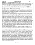
6. Unified Modeling Language (UML)
READINGS
The Unified Modeling Language (UML) is a diagrammatic
rather than a text language. It is like the diagrammatic
tools that electrical engineers use to specify and
communicate electrical/electronic circuit designs to each
other.
[Maciaszek01] - read chapters 2, 4, and start on chapter 5.
Unfortunately, there have been many diagramming methods
used in the past, each promoted by one of more institutions
or authors. Some were targeted toward special kinds of
software design.
UML is the first official standard for software engineers to
use for diagramming. In addition, it tries to be general
enough for different kinds of software designs.
UML can be used to specify required behavior (Use Cases),
static structure (e.g. Entity Relationship and Class
Diagrams), internal design dynamics (Interaction Diagrams
and Activity Diagrams), state behavior, and packaging and
deployment details.
© 2002 Russ Tront
Page 6-1
Last Mod: 2002-06-01
© 2002 Russ Tront
Page 6-2
Last Mod: 2002-06-01
References and Optional Readings:
[Booch99] “The Unified Modeling Language User Guide” by
Grady Booch, James Rumbaugh, and Ivar Jacobson,
Addison-Wesley, 1999. {This is the book on the UML. Every
software professional should own a copy! Do NOT buy the
other book called “The Unified Modeling Language Reference
Guide” as it, and the official standard at www.uml.org, are
very obscure theoretical specifications only useful if you are
trying to find out some subtle detail, or are writing a CASE
tool that will implement UML.}
[Larmon02] “Applying UML and Patterns: An Introduction to
Object-Oriented Analysis and Design and the Unified
Process, 2nd Ed.” by Craig Larman, Prentice-Hall, 2002.
{This is a very good book that introduces to many aspects of
design using the UML, and of the Unified Software
Development Process. Note that most students and grads do
not read enough about design concepts and other general
aspects of computing to be better as something other than
coder; in fact many do not even read books like “Code
Complete” about how to be good coders.}.
[Jacobsen99] “The Unified Software Development Process”,
by Ivar Jacobson et al., Addison-Wesley, 1999. {This is the
book on the USDP by the developers of USDP and UML. It is
an iterative lifecycle process for large systems. However, this
instructor (R. Tront) feels it muddles the concept of phases
and workflows unnecessarily. Nonetheless, it nicely
indicates which diagrams should be produced in which
phases of a project.}
© 2002 Russ Tront
Page 6-3
Last Mod: 2002-06-01
TABLE OF CONTENTS FOR SECTION
6. UNIFIED MODELING LANGUAGE (UML)......................... 1
6.1 HISTORY OF THE UML ........................................................ 5
6.2 USE CASES .......................................................................... 8
6.3 USE CASES INFECT DEVELOPMENT ................................... 10
6.4 USE CASE NARRATIVE ...................................................... 11
6.5 USE CASE DIAGRAMS ....................................................... 14
6.6
6.7
6.8
6.9
6.10
6.11
6.12
6.13
6.14
6.15
6.16
6.17
6.5.1
Use Case <<include>> Relationship ..........................................17
6.5.2
Use Case Generalization Relationships .......................................19
6.5.3
Use Case <<extend>> Relationship ...........................................22
CLASS DIAGRAMS ............................................................. 23
UML RELATIONSHIPS IN GENERAL ................................... 27
CLASS ASSOCIATIONS ....................................................... 28
AGGREGATION AND COMPOSITION ................................... 32
ASSOCIATION CLASSES ..................................................... 34
CLASS INSTANCES AND REFLEXIVE ASSOC. ...................... 36
QUALIFIED ASSOCIATIONS ................................................ 38
INHERITANCE/GENERALIZATION ....................................... 39
INTERFACES, ABSTRACT CLASSES, DEPENDENCY ............ 41
STATE MACHINES ............................................................. 45
6.15.1 Basic UML State Diagrams .........................................................47
6.15.2 Guards.........................................................................................49
6.15.3 Functions in State Machines ........................................................50
6.15.4 Mealy vs. Moore State Machine Specification..............................52
6.15.5 State Activities and Exit Actions...................................................54
6.15.6 Internal Transitions .....................................................................55
6.15.7 Start and Stop Icons .....................................................................56
6.15.8 Substates......................................................................................58
6.15.9 Concurrent State Machines..........................................................61
ACTIVITY DIAGRAMS ........................................................ 63
6.16.1 Swim Lanes and Object Flow.......................................................67
INTERACTION DIAGRAMS .................................................. 70
6.17.1 Collaboration Diagrams ..............................................................71
6.17.2 Sequence Diagrams .....................................................................74
© 2002 Russ Tront
Page 6-4
Last Mod: 2002-06-01
6.1
nor the recommended process that goes with it. Here is
where some of the key pieces came from:
History of the UML
There were many diagramming methodologies during the
1980s. These were methodologies because advice and
books usually accompanied them on how to use them in the
various phases of a project.
In the late 1980s and the early 1990s, the number of
methodologies proliferated as new object-oriented ones were
introduced and old ones were extended to handle objectorientation. It was like there were dozens of different ways
to do electronic circuit diagrams, and electrical engineers
didn’t understand the subtleties of each other’s diagrams.
Fortunately, in the mid-1990s three very prominent
methodologists (Grady Booch of Rational Software, James
Rumbaugh from GE, and Ivar Jacobson of Objectory AB in
Sweden) merged their methodologies under the company
www.rational.com. They took the best ideas from each of
their methodologies, and borrowed other very good ideas
from the other methodologists and published the UML. This
triggered a movement toward one standard. The UML is now
an international standard published by the Object
Management Group (www.omg.org and www.uml.org). Most
analysis CASE tools that used to be specialized for the
individual disparate diagramming methodologies have now
had to additionally support the icon shapes in the UML, or
they have died. Even MS-Visio supports UML icons. A few
possible exceptions that live on might be the diagramming in
some of the tools produced by database giants like Oracle.
• Booch contributed a lot of Object-Oriented (OO) concepts.
• Rumbaugh tried to integrate OO and database concepts.
• Jacobsen contributed the concept of Use Cases.
• Odell contributed stuff on classification.
• Shlaer and Mellor contributed object state cycles.
• Embly came up with the concept of Singleton classes.
• A methodology called Fusion contributed Operation
descriptions and numbering for messages.
• Wirfs-Brock contributed class responsibilities.
• Harel developed an elegant state chart system.
• Meyer contributed the concept of pre- and post-conditions.
• Gamma et al contributed the concept of patterns.
This list basically describes the birth over the last 20 years
of many software architecture ideas.
Rational Corporation makes very expensive analysis and
back end CASE tools. The analysis tool that you will use is
called Rational Rose.
These three methodologists (sometimes called the ‘three
amigos’ ) cannot take full credit for the UML diagramming
There are other competing products. One that comes to
mind is from www.togethersoft.com. (Note they have a nice
brief tutorial on UML in
www.togethersoft.com/services/practical_guides/)
© 2002 Russ Tront
© 2002 Russ Tront
Page 6-5
Last Mod: 2002-06-01
Page 6-6
Last Mod: 2002-06-01
Many of these tools will generate skeleton source code (in
several languages) from the diagrams. Some will take code
and reverse engineer it into diagrams. The Java product
from TogetherSoft is particularly good at doing this, and
doing it without having to leave special tags in the code to
allow you to modify either the code or the diagrams and regenerate the other.
Several of these tool vendors offer free test drives of their
products. They are either limited 30-day licenses, or are
slightly crippled (cannot have more than a dozen classes, or
cannot save/print certain kinds of diagrams). Nonetheless,
sometimes these restrictions might not be critical to you.
There are also some free tools, though they are somewhat
crude or restricted in their capability. Another SFU
instructor, Qusay Mahmoud, has a number of UML and
UML tool references at:
http://www.cs.sfu.ca/~qmahmoud/teaching/winter2002/c
mpt275/resources.html
6.2
Use Cases
Most of the time a computer is uselessly doing nothing.
When a user starts an operation (perhaps a menu
command), a sequence of interactions is started with the
user, the network, et cetera, until the command is done
(perhaps file is opened for word processing). Along the way
the user may be prompted and select a file path from a tree,
then possibly enter a file name from the keyboard, etc. This
sequence of interactions ending back in a quiescent state is
called a Use Case.
Note that a use case can also be started from a network
packet arrival, or a timer expiring.
[Booch98] states “A use case specifies the behavior of a
system or part of a system and is a description of a” …
“sequence of actions, including variants, that a system
performs to yield an observable result of value to an actor.”
Booch actually says it is a set of sequences, but this
instructor (R. Tront) doesn’t agree.
An ‘actor’ is an external person or computer process that
interacts with the application that is being designed.
Note that a use case is not a diagram, or an oval on a
diagram. Instead, it is a specification of behavior. Generally
this requires a lot of text (possibly augmented by interaction,
not use case, diagrams).
So you will hear various descriptions of a use case: function,
operation, sequence of interactions, or command. However
© 2002 Russ Tront
Page 6-7
Last Mod: 2002-06-01
© 2002 Russ Tront
Page 6-8
Last Mod: 2002-06-01
the point is that it is the specification of a planned sequence
of interactions with a defined beginning and end.
6.3
Use Cases Infect Development
It has realized in the last 1990s that use cases infect the
development process:
• They must be enumerated at least by simple name in the
requirements spec. Some narrative text for each use case
is very valuable to obtain/write as early as possible.
• Their design and implementation must be planned in the
project plan.
• The must be fully described by narrative text during
analysis. Their visual appearance must be planned in a UI
design or draft user manual.
• The collaboration between the various internal software
modules and class instances needed to implement the use
case must be planned in the USDP analysis model, and
designed with interaction diagrams in the design model.
• The parts of various modules that help implement the use
case must be coded.
• The use cases form ideal test cases
On rigorous projects, they are key elements of ‘requirements
traceability’.
© 2002 Russ Tront
Page 6-9
Last Mod: 2002-06-01
© 2002 Russ Tront
Page 6-10
Last Mod: 2002-06-01
6.4
Use Case Narrative
It is more important to write use case narratives than draw a
use case diagram. The idea of a use case is that it describes
in considerable detail exactly what the user should see and
do during the execution of a use case. In Extreme
Programming (XP), these are called user stories. In Rapid
Application Development (RAD), this is one of the goals of
getting customers and developers together (preferably off
site): to write descriptions of what the system is envisioned
to do and how each user command will unfold.
Use case narratives should not describe what would go on
internally in the software. You don’t want to be distracted by
that when gathering requirements and planning (designing?)
use cases.
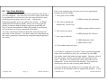
Here is an example of a use case story for an automated
banking machine (ABM):
1. User puts card in ABM.
2. ABM prompts for password.
3. User enters password
followed by <enter> key.
4. ABM prompts which account.
5. User selects account.
6. ABM prompts for amount.
7. User enters amount.
8. ABM dispenses cash.
9. ABM returns card
10. User takes card and cash.
In the above “sequence of actions” I have separated spatially
those that are done buy the user, and done by the ABM.
You might think this looks boringly simple. However, what if
the user wants another transaction after getting his/her
cash. He/She is not offered this choice after the cash is
dispensed! If you want this functionality, then someone
should say the use case is wrong and amend it.
Use case design is not boring if, as is usually the case, the
developer is not familiar with the application domain. If you
© 2002 Russ Tront
Page 6-11
Last Mod: 2002-06-01
© 2002 Russ Tront
Page 6-12
Last Mod: 2002-06-01
are unfamiliar with the application domain (e.g. pilot using
the space shuttle navigation computer, clerk entering of
insurance claims, foreman operating a pulp and paper mill,
etc.), then it is far from boring --- it is critical determining of
the required functionality.
This is the essence of use case design: making sure that the
customer of your software development company specifies
EXACTLY what they want. As much as it possible, this
should be determined BEFORE you start design of the
architecture. If you think the programmer can design these
interactions, you will be wrong in most case and thus have
to modify or scrap source code!
6.5
Use Case Diagrams
This instructor (R. Tront) thinks an emphasis on use cases is
extremely important. However he feels that Use Case
diagrams are overrated. Often they are just used to list the
use cases. But, a simple textural list is just as good for
that.
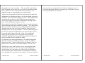
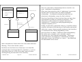
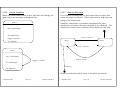
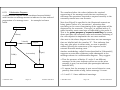
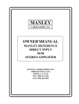
One good reason to draw use case diagrams is when there
are a variety of types of users, and each type of user only
invokes a particular subset of use cases appropriate to the
users type. The lines on a Use Case Diagram illustrate the
“associations” between types of users and the use cases they
typically invoke. Here is a use case diagram for an
Automated Banking Machine.
Withdraw
Cash
Customer
Deposit
Cash
Cash
Transport
Guard
Admin.
Access
A use case diagram has ‘Actor’ icons that represent users (or
another computer that interacts with the program being
© 2002 Russ Tront
Page 6-13
Last Mod: 2002-06-01
© 2002 Russ Tront
Page 6-14
Last Mod: 2002-06-01
designed), and use case ovals. The so-called ‘association
lines’ between actors and use case ovals are usually simple
lines. However, if the interaction is only one way, it is
possible to put an arrowhead on the association.
the use case are enumerated in a list or a diagram, one of
the most important things is actually get a narrative or stepby-step description for each one.
Notice how the guard that fills the machine with cash and
withdraws the deposits to take to the actual bank personnel
invokes a use case called “Admin. Access”. This allows him
to disarm the security on the ABM, prevent temporarily
users from using the machine, and allows opening up the
back of the ABM to get physical access.
Notice also that the Cash Transport Guard can also deposit
and withdraw cash like a normal customer. If he was doing
this as a normal customer, you could probably not bother
drawing lines for this; the guard could be though of just
morphing into an actual customer. The fact that that guard
has lies to Deposit and Withdraw use cases means that he
has to do this as part of his job. After he has finished
servicing the machine, he is expected to test that the
withdraw and deposit functions still actually work after he
has re-enabled and re-armed the ABM.
Of perhaps even more importance in the above diagram is
that the Customer is NOT expected to invoke the Admin.
Access use case. This is indicated by the absence of a line
between the Customer icon and the Admin. Access icon.
Though for a very small system, a use case diagram may
serve as the list of use cases the system will implement,
usually there are too many use cases to fit on a diagram,
and a textural list is a better way to enumerate all the use
case (perhaps 25 can then fit on a page). Of course whether
© 2002 Russ Tront
Page 6-15
Last Mod: 2002-06-01
© 2002 Russ Tront
Page 6-16
Last Mod: 2002-06-01
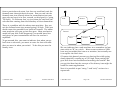
6.5.1
Use Case <<include>> Relationship
Note that in UML the term ‘Relationship’ is more broadly
used to describe any connection among things in a diagram.
There are a number of different subtypes of relationships; for
instance associations between data base entities, inheritance
relationships from subclass to superclass (called
generalization), dependencies, etc.
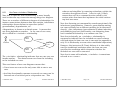
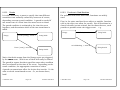
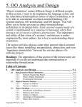
A dependency is drawn as a dotted arrow. It means that
one thing depends on another. In the case of use cases,
this is called an <<include>> relationship.
Place
Order
<<include>>
Validate
User
Customer
Track
Order
<<include>>
The <<include>> relationship indicates that one use case can
invoke another. The dotted arrow runs from the including
to the included use case.
reduces and simplifies by removing redundancy within the
narrative descriptions of each. Later in code, it likely
means there will be a common function called by the
various other functions that implement the other various
top-level use cases.
Note that factoring out commonality sounds suspiciously like
inheritance/generalization. However, generalization among
use cases actually has a different meaning (to be discussed
shortly). Also, inheritance/generalization is about inheriting
and modifying top-level functionality, not delegating lower
level common functionality to a common use case.
Note that technically, an <<include>> relationship is
supposed to indicate that the included use case is always
executed when the base use case is executed (as opposed to
only if it is Wednesday or some other conditional expression).
However, this instructor (R. Tront) believes it is also widely
used for conditional extension where the base use case
specifies the conditions which determine whether the
included use case will be executed.
Note that in some old textbooks, <<include>> is sometimes
referred to as <<uses>>.
This new feature of use case diagrams means that:
• Users icons are new not the only ones able to start a use
case.
• And that functionality common to several use cases can be
factored out of each and put in a dependent one. This
© 2002 Russ Tront
Page 6-17
Last Mod: 2002-06-01
© 2002 Russ Tront
Page 6-18
Last Mod: 2002-06-01
6.5.2
Customer
Use Case Generalization Relationships
Craig Larman in [Larman02] leaves Use Case Diagrams until
very late in his book, and emphasizes not to spend too much
time drawing use case diagrams as opposed to actually
writing use case narrative text. In particular, he and other
well-known authors he quotes, suggest that the other kinds
of use case relationships should be used VERY rarely. For
most case of use case relationships, the idea of <<include>>
dependency is adequate. You should NOT waste a lot of time
arguing with your teammates over whether you should use
generalization or <<extend>> instead of <<include>>.
Nonetheless, I will introduce these few other types of
relationships just so you will not be surprised to see one
sometime.
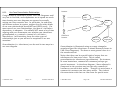
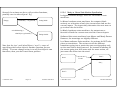
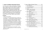
Generalization (i.e. inheritance) can be used in two ways in a
use case diagram.
Place
Order
<<include>>
Validate
User
Track
Order
Commercial
Customer
<<include>>
Check
Password
Check
Fingerprint
Generalization is illustrated using an empty triangular
arrowhead (just like inheritance is shown between classes in
UML Class Diagrams). The base or most general class it at
the arrowhead end.
Notice that there can be special kinds of actors that are
subclasses of a base actor class. This is called
generalization (or inheritance/specialization). For instance,
in some businesses, commercial customers perhaps get
special treatment. In the above diagram, I have adjusted it
(compared to the previous one) so that only commercial
customers can track their orders. Though it is not shown, a
commercial customer can also place orders. They inherit
this association with that use case from the parent actor.
© 2002 Russ Tront
Page 6-19
Last Mod: 2002-06-01
© 2002 Russ Tront
Page 6-20
Last Mod: 2002-06-01
More commonly in use case diagrams, generalization is used
to show that a use case is a specialization of another.
Though it is different, the specialized (sub use case) can
validly substitute for its parent. For instance, a customer
can be validated via normal means (Validate User use case),
but also it is equally acceptable that validation takes place
through a password or a fingerprint.
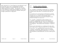
6.5.3
Use Case <<extend>> Relationship
This is a very confusing type of relationship.
An <<extends>> relationship is kind of like an <<include>>
except that the base case does not specify much about the
extension other than where it is inserted in the base use
case.
An extension use case determines itself whether it should
execute or not. It is as if the base use case branches to the
extension use case, which in turn decides using a
conditional expression in the narrative whether to insert
itself into the base use case or not.
An <<extend>> relationship is drawn similarly to an
<<include>> relationship, except the arrow appears to be
going in the WRONG direction. This is very confusing to
most readers of such diagrams, and also even to authors of
such diagrams. The arrow has the annotation “<<extend>>”
on it.
Because this relationship is so confusing and rarely used,
most readers you are targeting would not even understand it
if you drew it. You should therefore refrain from using
<<extend>> relationships. Before you use an <<extend>>
relationship, you also probably read Section 2.11.4.2 of the
UML standard to understand some even more subtle aspects
of it.
© 2002 Russ Tront
Page 6-21
Last Mod: 2002-06-01
© 2002 Russ Tront
Page 6-22
Last Mod: 2002-06-01
6.6
Class Diagrams
A key diagram in system design is the class diagram. This
diagram, amongst other aspects, primarily shows entity
relationships and also class inheritance. It is a kind of
diagram that shows static structure of the architectural
elements.
Before object-oriented techniques came along, there was no
inheritance and no class member functions to be show. The
predecessor was called an Entity-Relationship Diagram
(ERD). Now that we show inheritance and member
functions in addition to entity relationships, this instructor
(R. Tront) tends to call the new style diagrams ObjectRelationship Diagrams (ORDs), though the official UML
name is ‘Class Diagram’.
Like entities, classes are represented in class diagrams as
rectangles. The class icon is divided into 3 (and sometimes
even 4) areas:
• Class name
• Class member attributes (fields/variables)
• Class member functions
• Class responsibilities and/or other comments.
ClassName
+publicAttribute: ItsType
#protectedAttribute: OtherType
-privateAttribute: ItsType
-staticMemberField: ItsType
+publicFunction( )
#protectedFunction( )
-privateFunction( ): ReturnType
-staticMemberFunction()
Optional responsibilities/comments
space
Except for the class name area, any of these areas may be
blank or even missing if they are not important or take to up
© 2002 Russ Tront
Page 6-23
Last Mod: 2002-06-01
© 2002 Russ Tront
Page 6-24
Last Mod: 2002-06-01
too much space. You can usually easily tell which area is
present when the others are missing because member
attributes and functions have visibility icons (“+”, “#”, “-“, or
padlock-like icons) representing public, protected, and
private visibility. If you are not familiar with member
visibility (sometimes called member scope), consult your
favorite OO language textbook.
Even when some or more of the areas are missing, you can
always tell the area for functions by the parentheses
representing space for the parameters.
Attributes often have a type (expressed in the Pascal
language like manner: attribute followed by colon followed by
the attribute’s type). Sometimes, function return types are
shown this way too. However, where it is not important or
takes up too much space, the type is often left out of such
diagrams (though in a CASE tool, the type is stored for later
restoration to the diagram.
Speaking of ‘scope’, UML actually reserves that term to
indicate whether the member is an instance member or a
static member. Recall that static members are member
attributes and member functions that are not associated
with any particular instance. In fact, they are present even if
there are no instances of that class in existence. Though
this is not the main reason for static functions, in languages
that have no functions outside of classes (e.g. Java), plain
functions such as the math sin( ) and log( ) functions are
static functions of the Math class.
instance, a shepherd attribute might know, and a shepherd
function, might return a reference/address of the head of the
linked list of instances.
The static aspects of a class have both memory (static
attributes) and reactive ability (static functions). The static
functions can access the static attributes. The instance
functions can access and invoke static attributes and static
functions, respectively. (I.e. a sheep can read the shepherd’s
mind and kick the shepherd to get a reaction.)
Some authors wrongly state that static functions cannot
access instance attributes. This is simply wrong! It is
relatively common for static functions to access instance
attributes and instance functions, if the static function can
find/get a reference/address of an instance. A static
function cannot access instance members with the same
ease that an instance can access its own instance members
(using the so called ‘this’ pointer). However, it is common
for a static function to de-reference a reference to an
instance and get access to that particular instance. This is
done in the same way as any other class might access that
kind of instance. The shepherd functions have the added
ability (compared to other classes) of being able to access the
private members of instances of its own class.
Now that I have reminded you what static member attributes
and static member functions are, I will point out that static
members are underlined in UML class boxes.
Often static functions are used to create, manage, or find the
instances (like a shepherd and a flock of sheep). For
© 2002 Russ Tront
Page 6-25
Last Mod: 2002-06-01
© 2002 Russ Tront
Page 6-26
Last Mod: 2002-06-01
6.7
UML Relationships in General
6.8
In the old simple database analysis days, a ‘relationship’
specifically indicated a link over which you could navigate
using a foreign key from one data record to a ‘related’ data
record in a different entity.
However, UML uses the term ‘relationship’ to mean almost
any kind of line joining two elements of UML! A relationship
can be of type:
We have already seen a relationship between an actor and a
use case in a use case diagram.
However, in a class diagram, a UML association is a
database entity-like relationship between two classes. There
is often a foreign key in one class that allows instances of
that class to immediately know which instance of the other
class they are associated with.
• Inheritance (called specialization or in UML: generalization)
• Dependency (one element uses/includes/depends on
another)
• Realization (e.g. a class implements an interface)
Class Associations
Student
+
+
+
+
Name
Address
PhoneNumber
HighSchool
• Association (traditional database relationship)
1..*
Role1
graduated from
1..1
Role2
High School
SchoolName
SchoolAddress
SchoolPhone
© 2002 Russ Tront
Page 6-27
Last Mod: 2002-06-01
© 2002 Russ Tront
Page 6-28
Last Mod: 2002-06-01
Note that UML rarely discusses the concept of a value-based
foreign key, or even a reference or pointer based key. This
because UML started about the time object-orientation was
starting, and OO and database do not map well to one and
other. So a lot of initial OO analysis that the UML creators
worked on was not likely very database-oriented. This is
unfortunate, because now that we are applying OO to all
kinds of projects, we seem that class diagrams are really just
old style Entity-Relationship Diagrams in new cloths (with
some additional new adornment). However, they can just as
easily be used for database projects with the tiny
customization of adding some notation to indicate key
attributes and foreign key attributes.
This instructor calls the first number in a cardinality string
the optionality because it is usually either zero or one, and
indicates whether an object at the other end could possibly
not have any association with the class at the notation end.
I.e. A car might have had zero visits to the repair shop.
Associations have a number of standard adornments.
Note that notations such as 2..9 are possible in UML but
rare.
Usually an association has a name or a descriptive phrase.
This phrase has a particular direction, as sometimes
indicated by a black triangle. The triangle indicates the
direction to read (e.g. student graduated from high school).
There is an adornment at each end of the association
indicating the cardinality. UML calls this the multiplicity,
however this instructor (R. Tront) tends to use that term for
the latter number in each cardinality string.
The second number in a cardinality string indicates whether
the object at the other end could possibly have a relationship
with more than one object of the class at the notation end.
This instructor terms this multiplicity.
When doing requirements elicitation it is important to ask
about the optionality and the multiplicity at both ends (i.e.
four separate questions)!
Note that the first digit in a cardinality string cannot be “*”,
because the first digit represents the optionality rather than
the multiplicity.
1..1 means one and only one (abbreviated simply to “1”)
A third type of adornment is role names. I have not put
proper role names in the above diagrams, just place holders
“Role1” and “Role2”. I have not put role names because they
would be redundant with the names of the classes.
However, if the bottom class were Person rather than
Student, and if Person had other associations, it might be
appropriate to replace the string Role1 with “student” to
make it clear what role the upper object were playing in the
relationship. That same person might play a different role in
other associations it might have (e.g. UndergraduateTA).
© 2002 Russ Tront
© 2002 Russ Tront
1..* means a high school graduates 1 or more students.
0..* means zero or more (abbreviated simply to “*”).
0..1 means zero or 1.
Page 6-29
Last Mod: 2002-06-01
Page 6-30
Last Mod: 2002-06-01
A fourth, and rarely used adornment is a open style arrow
head. It is occasionally used to indicate data navigation
efficiency. In the above case, for any particular student, it
is very efficient to get to a student’s high school’s address
and other data via the foreign key named HighSchool in the
student instance. Contrast this with finding the student(s)
that went to a particular high school. This requires a slow
linear search of likely the entire student file! Though it is
easy to add such arrowheads, they needlessly complicate
and confuse the diagram (especially since arrow heads are
used for other things to be discussed shortly), and are not
used unless the author is trying to point out a specific
performance aspect of a design.
6.9
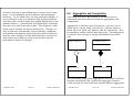
Aggregation and Composition
One thing new that UML seemed to introduce was an
adornment for associations to indicate aggregation and
composition.
Aggregation is another type of hierarchy, such as a car is
made up of a motor, body, and wheels. And the motor is
made up of the block, the pistons, and the carburetor. This
is sometimes called a whole/part hierarchy. The adornment
to indicate this concept is an open diamond at the whole
end.
Aggregate
Composite
2
1
*
PartClass
*
WeakPartClass
The interesting thing about aggregation is that the PartClass
instance associated with a particular aggregate instance
could actually be associated with several different aggregates
© 2002 Russ Tront
Page 6-31
Last Mod: 2002-06-01
© 2002 Russ Tront
Page 6-32
Last Mod: 2002-06-01
or any other classes. Or not associated at all. In other
words, the PartClass is able to stand on its own.
Composite aggregation is just a stronger form of aggregation.
It means that a WeakPartClass instance cannot exist except
as an associate of some composite instance. If the composite
instance is destroyed, so much the WeakPartClass instances
associated with it. Typically the composite instance is the
one that instantiates its parts, and it usually is the one that
destroys them (either before or at the same time as its own
destruction).
This instructor (R. Tront) finds these adornments interesting
but not very illuminating. Most of the time you can look at a
large class diagram and figure out which classes aggregate
which others just by the names of the classes.
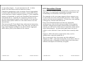
6.10 Association Classes
When there is a many-to-many association, as shown on the
next page, it is impossible to formalize/remember/store the
relationship in normalized, fixed length records.
The example on the next page suggests that a property can
be owned by more than one person (partners). And a single
person can own several properties. In the case, even putting
a foreign key at both ends will not do.
Even if the association does not have any particular
attributes (e.g. date of sale and percentage of the property
owned by that person for some reason does not need to be
stored), you still need a third class to remember which owner
owns what property. A particularly good name for this is
called a ‘cross reference’ class, because that is exactly what
it is.
However, UML calls this an association class, and in
addition has a special symbol for it.
That is not to say that you cannot use the traditional
diagram in UML. I am only saying that, if you want, there is
a particular way of denoting an association class that most
software developers will instantly recognize.
© 2002 Russ Tront
Page 6-33
Last Mod: 2002-06-01
© 2002 Russ Tront
Page 6-34
Last Mod: 2002-06-01
Initial Design:
6.11 Class Instances and Reflexive Assoc.
Property
Owner
+address
+phone#
*
*
Often, it is possible for an object instance to have an
association with another object of its own class. In that case
you can draw a so-called ‘reflexive’ relationship between a
class and itself.
List Node
Successor
Formalized as a Regular Class:
Property
+address
1
Land Title
+ownerName
+propAddr
* +date
*
+% owned
Owner
+name
+phone#
1
UML Notation for an Association Class:
predecessor: ListNode
Property
successor
Owner
*
*
+address
+phone#
Land Title
+date
+percentage
© 2002 Russ Tront
Predecesser
Page 6-35
Alternately, you can draw two named instances of the same
class, and show an association between them. Instances in
UML are indicated by underlining the text in the top portion
of the rectangle. You can put either just an instance name,
or an instance name and class name separated by a colon,
or even just a class name preceded by a colon (e.g.
Last Mod: 2002-06-01
© 2002 Russ Tront
Page 6-36
Last Mod: 2002-06-01
:ListNode). The latter indicates an anonymously named
instance. You should underline the entire text in the top
portion of the rectangle, no matter what the format, if you
want the reader to understand that the rectangle represents
an instance rather than a class.
6.12 Qualified Associations
There is a rather weird adornment for an association called a
‘qualification’. [Maciaszek01] states: “The concept of a
qualified association is a tough and controversial
proposition”. This instructor (R. Tront) is thus hesitant to
cover this subject, because it is seldom used and obscure.
Let me say that a qualified association often means that
there is a variable length list on the qualified end that points
to instances on the unqualified end. Essentially this is a
‘repeating group’. This is sometimes done to formalize
many-to-many associations without resorting to an
association class. However, it then gives up the fixed-lengthrecord nature of an association class. Giving this up is not
a problem if you are dealing with variable length lists in
RAM, but it is rarely useful in information systems.
If you see something like this, you will have to look up more
on your own [Maciaszek01, Larman02, Booch99].
[=[-]
Product
Catalog
© 2002 Russ Tront
Page 6-37
Last Mod: 2002-06-01
© 2002 Russ Tront
ProductSpec
ItemId
Page 6-38
Last Mod: 2002-06-01
6.13 Inheritance/Generalization
Since UML was based on object-oriented concepts, it thus
has a mechanism to illustrate that one class inherits from
the other.
Base/Super Class
The above diagram illustrates three classes called
“Base/Super Class”, “SubClass”, and “ChildClass”. A
hollow triangle pointing at the base class, and a solid line
indicate this kind of relationship. Note that “Base/Super
Class” has one instance attribute, “SubClass” has two, and
“ChildClass” has three.
Note that UML does allow a subclass to inherit instance
attributes and instance member functions from two or more
base classes (not shown). This allows it to model the
multiple inheritance that is possible in languages like C++.
+ attribute1
SubClass
ChildClass
+ subAttrib
- childAttrib
# otherAttrib
Note that the inheritance relationship is also commonly
termed Generalization/Specialization. This indicates that
subclasses are specializations of base classes. In UML, the
term Generalization is widely used.
© 2002 Russ Tront
Page 6-39
Last Mod: 2002-06-01
© 2002 Russ Tront
Page 6-40
Last Mod: 2002-06-01
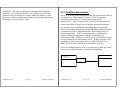
6.14 Interfaces, Abstract Classes, Dependency
The Java programming language, and some other
programming facilities (e.g. ActiveX/COM/DCOM, and
CORBA) provide or rely on the concept of ‘interfaces’. An
interface is basically just a list of instance member
functions, and possibly some types and constants. It is
used to advertise some functionality common to several
classes even though those classes are not related by
inheritance. Basically this advertisement takes the form of
function prototypes (sometimes called function signatures).
On the other hand, it is common when programming a
number of classes that are related by inheritance, and that
have some instance functionality in common, to define that
common functionality in the base class. This is done even if
the base class does not have enough functionality or
functional implementation to actually be useful itself. In
that case, you leave the bodies out of some base class
function definitions and/or (depending on language) declare
the base class ‘abstract’. This is called an abstract class
and is a fairly common OO design.
Because these instance functions have the same signature,
they can be called polymorphically. The interface or
abstract class is specified in the implementing or sub class
declaration, and the compiler checks that an implementing
or subclass does actually implement that exact function
signature.
When you use polymorphism via interfaces, it is called
interface polymorphism. C++ does not provide interfaces or
interface polymorphism. Java uses interface polymorphism
extensively, especially in the Swing GUI library.
Java however does not have multiple inheritance. However,
you can get almost the same thing in most possible
programming circumstances you can think of using multiple
interfaces (which Java does provide).
For more information on abstract classes and/or interface
polymorphism, ask to see this instructor’s (R. Tront) C++ or
Java course notes.
So, with that said, let’s move on to UML’s way of illustrating
this:
Though interfaces and abstract classes tend to be somewhat
different, they provide the same kind of feature. They allow
someone to declare at least function signatures that should
be supported among a number of classes, without
programming the functions themselves. Of course a
particular function itself may be differently implemented in
one class than another. But the key thing is that though
differently implemented, this function in the two different
classes has the same signature.
© 2002 Russ Tront
Page 6-41
Last Mod: 2002-06-01
© 2002 Russ Tront
Page 6-42
Last Mod: 2002-06-01
AbstractClass
-
notice
italicized
class
name
Inherit
There are two kinds of relationships that an interface can
have: realization or dependency.
<<interface>>
MyInterface
Interface2
+ func1( )
+ func2( )
Note that Java allows a class to inherit from one base class
and implement/realize any number of interfaces. This
allows Java to have almost the multiple inheritance
capability of C++ without the awful programming and
compiler complexity of C++.
Realize/
Implement
<<use>>
SubImplement
When one class announces that it ‘implements’ a particular
interface that is shown with a so-called ‘realization’
relationship. A realization relationship looks likes an
inheritance relationship, except the line is dashed.
UsesClass
Finally, to show that a particular class (e.g. UsesClass above)
actually calls some of the functions of an interface (no matter
which one or more classes actually implement that interface)
it is illustrated with a dotted dependency arrow.
Note that there are about 17 different kinds of dependency.
We earlier saw <<extend>> and <<include>> when
discussing Use Case Diagram relationships. The dashed
arrow can also be stereotyped (i.e. labeled) with 15 other
dependency types, one of which is <<use>>. See [Booch99]
for information on the others.
Notice that abstract classes have their class name italicized.
Warning: This is often hard to notice.
Interfaces can be shown one of two ways: in a class-like
rectangle with a stereotype label of <<interface>>, or in an
abbreviated form as a circle (if you don’t want to bother
showing/listing the functions in the interface).
© 2002 Russ Tront
Page 6-43
Last Mod: 2002-06-01
© 2002 Russ Tront
Page 6-44
Last Mod: 2002-06-01
6.15 State Machines
It is very common to model software as a finite state machine
(FSM). This is because a software program or program
element (e.g. class instance or class static part (shepherd))
often needs to exhibit behavior that is state or mode
dependent. What this means that it responds differently to
the exact same event hitting it, when that event hits it at
different times. This is because it is in a different mode or
state, and its reaction is supposed to be dependent on some
state or mode of the program element. R. Tront calls this
behavior that is dependent on historical context. I.e. The
past history that has driven the element into its current
state. Though there is no need for the program element to
remember all the past events that have happened to it, it is
important to remember some essential data called the
current state. Sometimes the state is Boolean, or a set of
Booleans, or the value or contents of a variable.
Most engineers and computing science students understand
state machines, though as taught in the early years of
university they are usually digital circuit designs where the
events are input values at the moment of a clock tick.
Similarly, outputs are usually voltages.
• A blocking wait on input (e.g. read from keyboard, or read
from network socket). When the read function returns,
that is considered the event. The return usually is
accompanied by some data.
Actually, UML defines 4 types of events:
1) function incoming call event.
2) change event (e.g. “when (car arrives)”).
3) <<signal>>. A signal may or may not have parameters.
4) time event (e.g. “after (2 seconds)”).
UML is not just supposed to be software-oriented, so these
different kinds of events (e.g. the text “when”) are acceptable.
FSMs are a valuable specification mechanisms for software
behavior at the system, program, and even object level.
Their advantages are they formal and rigorously definitive,
and finite. Because they are finite, they are completely
testable in a finite amount of time.
In software, the events tend to be of two quite different
forms. Either:
• A local or remote function call hitting a module, instance,
or static member function. Such an event carries data in
the function parameters.
© 2002 Russ Tront
Page 6-45
Last Mod: 2002-06-01
© 2002 Russ Tront
Page 6-46
Last Mod: 2002-06-01
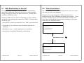
6.15.1
depending on whether it is in the full, part-full, or empty
states.
Basic UML State Diagrams
The finite state machine diagram notation in UML is a slight
modification of State Charts as developed by Harel.
Event 1/ Action A
State 2
State 1
Event 1/ Action B
Also note that it is not defined what this state machine
would do if Event 2 hits it while in State 1. This is a very
dangerous state machine design; both the designer and the
programmer may overlook this oversight. Or the
programmer may program it opposite to what the state
machine author assumed. To determine if there are
state/event pairs missing from a complex diagram, draw a
state table with a row for every event for every state. Fill in
the transitions and actions. If there any rows that are blank,
ask the customer what they want the machine to do in that
case (more requirements elicitation). This is a powerful
design review technique that almost always shows up errors
and oversights in a complex state machine spec.
Event 2 / Action C
States are rounded corner rectangles.
Transitions are arrows labeled with the event that causes the
transition and other optional aspects like the action
(reaction?) provided by the state machine.
Notice above that Event 1 causes a different action
depending on whether the current state is State 1 or State 2.
This is quite different than calling a cosine( ) function which
responds the same to every call.
However, many software elements will not do what you tell
them to. Just because you call myStack.push(myVar)
doesn’t mean it will do this. myStack will react differently
© 2002 Russ Tront
Page 6-47
Last Mod: 2002-06-01
© 2002 Russ Tront
Page 6-48
Last Mod: 2002-06-01
6.15.2
Guards
6.15.3
It is often necessary to want to specify that two different
transitions can mutually exclusively come out of a state,
depending on some guard condition. A guard is needed if
two arrows out of a state have the same event on them!
The guard condition is evaluated at the time the event
happens, and determines which of the two transitions is
taken.
Functions in State Machines
For software finite state machines, functions are widely
used.
First, in the state machine for an object or module, function
calls to the object are often the events. Not all functions in a
class’s behavior is state-related, but for those that are, each
provides a possible state exit trigger event. e.g.
Hungry
Hungry
Event 1[raining] / Action A
classEnds( ) / Action A
Eating Inside
Eating Inside
arriveInMorning( ) / Action B
Event 1 [sunny] / Action B
Eating Outside
Eating Outside
Notice that both arrows from the Hungry state are triggered
by the same event. Which one of these will really be taken?
The guard in square brackets specifies some other condition
that is evaluated at the time of the event. Depending on the
result condition, the appropriate transition is taken.
A guard can sometimes affect the Action that results. Or the
state to which transitioned occurs. Or, as shown above,
both!
© 2002 Russ Tront
Page 6-49
Last Mod: 2002-06-01
© 2002 Russ Tront
Page 6-50
Last Mod: 2002-06-01
Second, the actions can be to call yet other functions,
possibly even in other objects! E.g.
classEnds( ) / var.goInside( )
Hungry
Eating Inside
arriveInMorning( ) /
6.15.4
Mealy vs. Moore State Machine Specification
In digital hardware design, there are two kinds of state
machines.
In Moore hardware state machines, the outputs (think
actions) are a function of only the current state and not the
current inputs. The inputs only determine the next state to
go to when the clock ticks.
In Mealy hardware state machines, the outputs are a
function of both the current state and the current inputs.
otherObject->goOutside( )
Eating Outside
Note that the ‘var.’ and ‘otherObject->’ are C++ ways of
specifying which other object’s member function you are
calling. If a state change action is to call that object’s own
functions, then you don’t need these prefixes.
Software finite state machines have Moore and Mealy flavors.
However, the meanings are slightly different.
In a Moore software finite machine, the actions do NOT take
place on transitions. The actions on all the different
transitions going into a particular state are dependent only
on the state that is being entered. So instead of labeling all
the arrows going into that state with the same action, we
just move the action into the state!
State 1
State 3
Event1
entry / Action1;
foo( );
Event2
State 2
© 2002 Russ Tront
Page 6-51
Last Mod: 2002-06-01
© 2002 Russ Tront
Page 6-52
Last Mod: 2002-06-01
Notice how a solid line divides the state icon. The state
name is in the top area.
Notice how the action entering the state is designated with a
“entry/” label in the lower half of the icon.
Pure Mealy software finite state machines are the opposite;
they never have actions within a state but only on the
arrows. Most of the state machines earlier in this section are
Pure Mealy style.
General Mealy software finite state machines have actions on
both the transitions and in the states.
Programming software Moore vs. Mealy implementations are
slightly different. We will discuss this later.
6.15.5
State Activities and Exit Actions
In addition to entry actions, a state can have activities that
happen during the state. Essentially entry actions are
things that happen during a state, but there is an implied
meaning that an entry action happens quickly and is over
and the state machine waits for a long subsequent time in a
state. However, if you want to descriptively say that a yellow
light is on during the entire time of a state, it is easier to do
this with a state activity rather than turn the light on during
entry and turn the light off during exit (though the latter
might have to be the way you implement this in software).
So the most general state looks like this:
State 3
entry / yellowLight( );
do/ monitor light.
exit/ lightOff( );
Notice the use of the keywords “do /” and “exit /”.
Exit actions are useful when you want to do something while
exiting the state, no matter which transition you take out of
the state. It provides an economy of expression compared to
having to put the exit action on every transition arrow out of
the state.
© 2002 Russ Tront
Page 6-53
Last Mod: 2002-06-01
© 2002 Russ Tront
Page 6-54
Last Mod: 2002-06-01
6.15.6
Internal Transitions
6.15.7
When an event causes some action, but does not change the
state, there are two ways to diagram this:
State 3
Start and Stop Icons
It is common to designate the first state that an object has
when the object is created. This is done with a large dot icon
going to the initial state.
Similarly, sometimes a transition terminates the state
machine or the object the state machine is in is deleted. The
terminal or ‘death’ state is shown with a bulls-eye-like icon.
entry / yellowLight( );
do / monitorLight.
Event 1/ Action A
trigger( )/ Action23.
State 2
State 1
exit/ lightOff( );
Event 1/ Action B
State 3
entry / yellowLight( );
Event 2 / Action C
trigger( ) / Action23
do / monitorLight.
shutdown( ) /
exit/ lightOff( );
Notice how the first (birth) state is not what you would
© 2002 Russ Tront
Page 6-55
Last Mod: 2002-06-01
© 2002 Russ Tront
Page 6-56
Last Mod: 2002-06-01
expect, but that is why we have a start icon, to make sure
the reader does not wrongly infer the initial state.
It is likely possible to label the transition to the initial state,
but it is possible to assume it is just set by object
constructor, or program start up code for the main, or global
variable initial values, or static aspects of objects (in the case
of a state machine within the static (shepherd) part of a
class.
6.15.8
Substates
Humans often attempt to design very complex things. The
only way we can handle them though is through some kind
of hierarchical decomposition. UML state machines are
hierarchically decomposable. Here is an example of an
automobile automatic transmission:
It is quite common to see the death transition labeled with
the event causing death.
Park
Reverse
Neutral
Forward
First
Second
Third
Notice how we have modeled the Forward sub-state as a submachine. Sometimes you do not bother to draw the arrow
entering the forward state all the way to the initial sub-state.
So you use the birth icon again.
Also, note that the exit from the sub-machine does not come
from any particular sub-state. We could draw it coming
© 2002 Russ Tront
Page 6-57
Last Mod: 2002-06-01
© 2002 Russ Tront
Page 6-58
Last Mod: 2002-06-01
from a particular sub-state, but then we could only exit the
forward state through that sub-state. But you can exit the
forward state into neutral when the transmission (not your
gear selector lever) is in first, second, or third gear (i.e. going
120 kph!). To illustrate that, we just show the exit from the
sub-machine coming from the boundary of the submachine.
There is a problem with the above state machine. Say you
exit the forward state into neutral going 120 kph. Then you
decide move the gearshift lever back to Forward. The above
state machine says you go into first gear. Most mechanics
would tell you that if this happened, you would leave bits
and pieces of your transmission all over the road as it
exploded!
To get around this, you want to indicate that when you go
back into a sub-state, you want to enter the last sub-state
that you were in when you exited. To do this you use the
history icon:
Park
Reverse
Neutral
H
Forward
First
Second
Third
We can indicate that a sub-machine is to remember its last
state with an “H” in a circle. More recent versions of UML
have not just added this icon as a notation, but actually use
it to replace the birth icon.
Of course this doesn’t prevent you leaving first while going
slowly downhill, coasting up to 120 kph, then putting the
gear shift lever into forward and watching the results! But
you get the idea that the concept of the history icon might be
useful for some applications.
Note it is possible to put “entry/” and “exit/” actions in a
superstate.
© 2002 Russ Tront
Page 6-59
Last Mod: 2002-06-01
© 2002 Russ Tront
Page 6-60
Last Mod: 2002-06-01
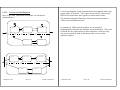
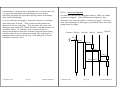
6.15.9
Concurrent State Machines
Here is are two, equivalent examples of concurrent
submachines:
P a rk
P a rk
R ev erse
S ta te L
S ta te R
R ev erse
N e u tra l
S ta te L
© 2002 Russ Tront
N e u tra l
In the top diagram, both sub-machines are started when the
super-state is entered. The super-state is NOT exited until
BOTH sub-machines have gotten to their death state.
The bottom diagram illustrates the same concept with socalled ‘synchronization bars’.
In summary, UML state machines are a powerful
diagramming notation for software state machines. They can
be used for any other kind of state machine, because they
are not necessarily tied to function calls, or any other
software aspect.
S ta te R
Page 6-61
Last Mod: 2002-06-01
© 2002 Russ Tront
Page 6-62
Last Mod: 2002-06-01
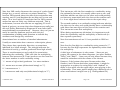
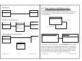
6.16 Activity Diagrams
Requirements
Activity Diagrams are a surprising part of UML. Early
versions of UML had data-flow-like diagrams, but they were
dropped from the standard. Then, Activity Diagrams
appeared. But they were not really rooted in the previous
work of any of the three UML authors.
Plan
Activity Diagrams are a special kind of state diagram where
each state is transitioned out of without the kick of an event.
In essence, they are like flowcharts (not data flow diagrams)
that are used to illustrate source code branching. However,
they also include aspects of event diagrams from Jim Odell,
and aspects of Petri network diagrams.
[Rejected]
[Accepted]
UI Design
Arch. Design
Write Manual
Write Tests
Code
Testing
© 2002 Russ Tront
Page 6-63
Last Mod: 2002-06-01
© 2002 Russ Tront
Page 6-64
Last Mod: 2002-06-01
In the above diagram you can see some of the features of an
activity diagram:
• There are start and stop/death icons.
• The activities are usually drawn with rounded rather than
semi-rounded left and right sides. Activities may be short
or long term actions that results in the computation,
return, or creation of some value or object.
just like old flowcharts used to be used. You can even put
source code statements into the activity icons!
This instructor (R. Tront) has even read where you can
hierarchically decompose an activity icon into finer-grained
activity diagrams, though I have never seen this done.
• There are no events on the exit arrows from an activity,
indicating they are ‘triggerless’ or ‘completion’ transitions.
They are take place as soon as the activity is completed!
• There are diamond-shaped branching diamonds whose
exits have mutually exclusive guards. Note that [else] is a
UML pre-defined acceptable guard for one exit.
• Activity diagrams are EXCELLENT for illustrating
concurrently. This is done in the Petri Net style, using a
solid bar as both a forking symbol and join symbol. The
activity following a join bar does NOT begin until all
incoming transitions are present.
Activity diagrams can show concurrency of execution
threads, or OS processes, or multiple computers in different
departments, or of staff in different departments working
simultaneously.
They are also good for illustrating workflow modeling within
a company or any other kind of system.
Finally, they are good for illustrating the computation within
a specific C++ or Java function. In this regard, they are used
© 2002 Russ Tront
Page 6-65
Last Mod: 2002-06-01
© 2002 Russ Tront
Page 6-66
Last Mod: 2002-06-01
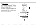
6.16.1
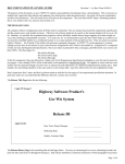
Engineering Dept.
Swim Lanes and Object Flow
Activity diagrams can be divided to show responsibility
(class, module, human, or department) for each activity.
Just like a swimming pool can be divided into swim lanes
separated with a rope, so an activity diagram can be
separated with lines. (Older books use dashed lines, but the
newest version of UML specifies solid lines).
In addition, an activity diagram can show which processes
produce which objects and which consume objects. This is
called object flow.
QA Department
Tech. Writing
Requirements
Plan
Project Plan
[Rejected]
[Accepted]
UI Design
Arch. Design
Code
Manual
Write
Manual
Write Tests
Test Cases
Testing
© 2002 Russ Tront
Page 6-67
Last Mod: 2002-06-01
© 2002 Russ Tront
Page 6-68
Last Mod: 2002-06-01
The swim lanes clearly show which department is
responsible for which activity. Some of the documents or
objects even physical parts produced can be shown with
dependency arrows. Where a dependency arrow to a
produced object and from a produced object to the next
activity redundantly shows the control ordering, the solid
transition arrows can be removed.
Note that the same object instance can show up in different
places on a diagram in different states. e.g. an invoice in the
received state, and later in the paid state. This duplication
of the object is sometimes done just to unclutter the
diagram. The state of the object is can be shown in square
brackets after the object name. e.g. :Invoice [paid].
In summary, activity diagrams provide a beautiful way to
diagram process or activity dependency. This is control
dependency between activities/computations. Note that this
is unlike old Data Flow Diagrams (DFDs) that show
precedence-lacking data flow, rather than control flow
precedence.
In addition, activity diagrams are an excellent way to show
that the order of two activities is irrelevant or can happen
concurrently. Note it is sometimes important to express
precedence irrelevancy, or concurrency, so as to later allow
software implementers maximum flexibility in their
implementation (this might allow them to improve
performance).
6.17 Interaction Diagrams
An important part of design is planning sequence of function
calls (or messages being passed) that are needed to
implement any particular use case. In fact, it is not
uncommon to plan several different variants (called
scenarios) of a use case. One might show normal
processing, while another might show how the use case
handles a certain error condition.
It is also possible to take the union of all interaction
diagrams and thus come up with a diagram that shows all
function calls to each class. This will provide an inventory
of the names and parameter lists for all the functions that
need to be written for a new class. This union is best done
from collaboration rather than sequence style interaction
diagrams. Though some methodologies provide such a
diagram, UML does not. However, a UML CASE tool like
Rational Rose can build up the member function list for each
class as you add more and more uniquely named functions
calls terminating at a particular class. The result is a
wonderful way to synthesize the class requirements from the
system use case requirements. This importanly bridges the
so-called ‘design gap’.
UML provides two different but almost equivalent diagrams
for drawing object interaction: collaboration diagrams and
sequence diagrams.
Finally, swim lanes show which class, person, or
department, has the responsibility to do (the computations
in) the activity.
© 2002 Russ Tront
Page 6-69
Last Mod: 2002-06-01
© 2002 Russ Tront
Page 6-70
Last Mod: 2002-06-01
6.17.1
Collaboration Diagrams
A collaboration diagram shows numbered arrows labeled
with function or message names to indicate the time ordered
progression of a message trace. An example is shown
below.
ObjectA
1:Start()
ObjectB
2:find()
2:check()
3:get()
Another methodology called Fusion described in [Coleman94]
suggests an even more elaborate prefix adornment to the
messages shown in a collaboration diagram. They suggest:
• That the presence of both a 2’: and a 2: on different
messages in the trace indicates either one or the other
message is sent, but not both (the apostrophe indicates
boolean NOT).
ObjectE
ObjectD
Note that ObjectE is specified in the illustrated scenario as
being ‘gotten’ before it is ‘overwritten’, otherwise data
necessary to the correct functioning of the application will be
destroyed by the overwrite. Thus get( ) is prefixed with a 3:,
while overwrite must come later as indicated by the prefix 4:.
This is the prime purpose of scenario modelling: to reason
about and plan the necessary calls and necessary ordering of
the calls required to implement the use case scenario.
Also note in the above diagram that there are two messages
that are labelled with the number “2”. This indicates that
they may take place in either order, or even in parallel,
without affecting the correctness of the response to the
external scenario-starting event.
ObjectC
4:overwrite()
The numbers before the colons indicate the required
sequencing of the message sends that are necessary to
effectuate the operations required to respond correctly to the
externally-started use case scenario.
• 2* means that the message is sent several times in a row,
possibly from within a loop, before message 3 is sent.
• 2.1 and 2.1.1 have additional meanings.
© 2002 Russ Tront
Page 6-71
Last Mod: 2002-06-01
© 2002 Russ Tront
Page 6-72
Last Mod: 2002-06-01
Unfortunately, message trace diagrams for a scenario are not
very good for completely documenting the trace with a
narrative justifying the particular design choice of message
calls and call ordering.
It is very common to supply a separate narrative to indicate
what each step is doing. This is often located below the
diagram or on the next page. The narrative for a use case
discusses only externally visible behavior, and discusses it in
customer terms. In contrast, such a narrative for an
interaction diagram describes internal program functioning,
and describes in terms that are perhaps very technical or
implementation name specific (e.g. Java Swing GUI, Oracle
Database connector, etc.).
6.17.2
Sequence Diagrams
An alternate interaction diagram format is UML’s so-called
‘sequence diagram’. Like collaboration diagrams, they
illustrate arcs between nodes in a directed graph. But they
have the advantage of offering an (unshown) linear time axis
going down the page.
Customer ObjectA
ObjectB
ObjectC
ObjectD ObjectE
EV1()
Start()
Check()
Find()
Get()
Overwrite()
© 2002 Russ Tront
Page 6-73
Last Mod: 2002-06-01
© 2002 Russ Tront
Page 6-74
Last Mod: 2002-06-01
This is a great diagram. It shows the same information as a
directed graph like a collaboration diagram, yet has a linear
progression in time as you go down the page. It shows
which object is to initiate what actions in which others in
which order.
One drawback is that it forces a time line, and thus can’t
show two messages that could be sent in either order, or in
parallel.
The tall skinny rectangles represent the time the thread of
execution control exists in or through the object. Remember
that the control thread is in an object, even if that module
has synchronously called another. It has temporarily passed
control to another, but it still retains control when it returns.
So the height of the rectangle suggests, for synchronous
calls, the duration between it’s reception of a call, and its
return to the caller. Note that it is not always necessary to
use the tall skinny rectangles to indicate the duration the
control thread is in a particular object; sometimes we just
use a simple vertical line.
Also note that the diagrams can look a little different if
asynchronous messages are being illustrated. [Jacobson92]
suggests using:
two threads, two processes, or two computers proceed to
work on the problem in parallel.
Additionally, information is normally written (in the space on
the left if there is room, else below) describing what each
step in the scenario is to do, and under what conditions. The
narrative can include IF conditions regarding whether a
message will be sent, and loops indicating that messages can
be sent repeatedly. Thus sometimes the narrative looks a lot
like pseudo-code, though this is not because this code will
ever become source code in a particular module. The source
code that gets executed for a scenario instead may (or many
not) be spread out in a distributed manner over many
objects that participate in the scenario; this pseudo-code
just documents the logic which, when spread among the
objects, will control the required response for the scenario.
At the bottom of the page, you can document why you, as
the scenario response architecture designer, decided to do it
a particular way. Remember, often there are several options
as to how you might have architected a response. Designing
how the trace flows is A MAJOR ASPECT OF DESIGN.
for Synchronous messages (i.e. calls)
for Asynchronous messages
Of course asynchronous messages are often used to
illustrate the splitting of a thread of control, where perhaps
© 2002 Russ Tront
Page 6-75
Last Mod: 2002-06-01
© 2002 Russ Tront
Page 6-76
Last Mod: 2002-06-01