Transcript
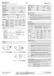
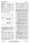
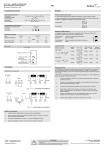
PA 01 A/B/C X1X - USER MANUAL
Photoelectric Amplifier Series
tel
EN
1-channel automatic/manual photoelectric amplifier
Output Logic
Product Data
Detection (thru beam)
Electrical Data
Supply voltage
Voltage tolerance
Power consumption
Output: relay
Output: transistor
12-30 V ac / 12-36 V dc, 115 V ac or 230 V ac
+/- 15%
Max. 2.5 VA
1 open / 1 closed, 250 V ac / 3 A, 120 V ac / 5 A
100 mA / 36 V dc
Object present
LT
7
1
3
Output
indicator
Closed
On
Open
Off
Open
Off
Closed
On
4
11
LR
7
1
3
4
1
3
4
1
3
4
Light operated
11
-10 to +55 ºC
IP 40
7
Dark operated
LT
Approvals
11
LR
7
Light operated
Applicable Remote Sensors & Sensing Ranges
Remote Sensor Series
101
100
110
Sensing Range
Long range mode
8m
N/A
N/A
Short range mode
2.5 m
10 m
23 m
Note: Long range mode must only be selected with the 101 series.
Illustration
PA 01 A
11
Transistor
Output
Dark operated
Object absent
Environmental Data
Temperature, operation
Sealing class
Relay
Output
Output mode
120
Manual Sensitivity Adjustment
N/A
45 m
Maximum sensitivity can be used for most applications and is advised for applications with
contaminated environments e.g. dirt, water and dust. Increase the sensitivity to maximum by
turning the potentiometer to full clockwise position.
PA 01 B/C
Sensitivity adjustment may be required in applications where objects to be detected are small
or translucent. Proceed with the following steps:
PA 01 B
PA 01 C
Connection
1
Begin with turning the potentiometer to MAN position. Manual sensitivity adjustment
mode has now been selected.
2
Increase the sensitivity to maximum by turning the potentiometer to full clockwise
position.
3
Check there is no object present interrupting the beam and the sensor pair is
correctly aligned and within their specified sensing range.
4
Select target object with smallest dimensions and most translucent surface.
5
Place target object between remote transmitter and receiver sensors. If the output
status changes, adjustment is not required. If the output status has not changed
proceed to step 6.
6
Decrease the sensitivity by turning the potentiometer counter clockwise until the
output is activated.
7
Remove target object. Observe the output status has changed.
Wiring Diagrams
If the signal level is low, the green LED (signal status) will flash slowly. In general, it
is recommended to increase the sensitivity till the LED goes on and to check the
following:
Alignment of sensors
Transmitter and receiver sensors are within sensing range
Sensor heads are not excessively contaminated
Transistor output — PA 01 X 61X
Automatic Sensitivity Adjustment - Teach-In
PA 01 A/B/C
Automatic sensitivity can be used in applications where changes in the environment occur e.g.
change of ambient light or moderate contamination. This adjustment must not be used in
applications where the environment is very contaminated.
1
Observe that no object is between remote transmitter and receiver sensors.
2
For PA 01 A proceed to step 3
For PA 01 B/C turn the potentiometer to full counter clockwise position to AUTO
and proceed to step 3.
3
Push the RESET / TEST button to initiate teach-in. The green LED will flash when
automatic adjustment is in progress.
4
When the automatic adjustment has completed, the green LED will be stable. The
system is now adjusted for optimal detection.
5
Move an object in and out of the detection area. Observe on the yellow LED that the
output changes correctly (refer to Output Logic table).
6
For a new adjustment, push the RESET / TEST button to initiate teach-in.
Relay output — PA 01 X 51X
Connection Steps
1
Check the power supply and output of the amplifier type.
2
Make sure power is off. Connect wires to the 11-pin socket according to wiring diagram.
3
Plug-in the amplifier into the 11-pin socket. Turn power on.
4
When the amplifier is operating, the green (signal status) LED is on.
If a severe disturbance occurs, the green LED (signal status) will flash quickly.
Adjustments
Time Delay Adjustment
DIP Switch Settings
DIP Switches are located on the back of the amplifier.
ON
1 2
ON
1 2
ON
1 2
ON
1 2
PA 01 C
The on delay enables output signal to only activate if an object in the detection area is present
for the adjusted time period (In Dark operated mode). The off delay enables output signal to
remain activated for the adjusted time period. The time delay is adjustable between 0-10 sec.
PA 01 A
Model
PA 01 B
PA 01 C
Long range
Long range
Long range
Short range
Short range
Short range
Light operated
Light operated
On delay
Test Input
Off delay
The transmitter can be disabled and enabled for test purposes. Make sure no object is present
in the detection area, between remote transmitter and receiver sensor, when test is activated.
When the transmitter is disabled, a change in output should occur.
Dark operated
Dark operated
Light operated: enables the output to be inactive when there is an object present.
Dark operated: enables the output to be active when there is an object present.
1
Select on delay or off delay using the DIP switch. Refer to DIP Switch Settings.
2
Increase or decrease time delay by turning potentiometer clockwise or counter
clockwise respectively.
Disable transmitter
Push RESET / TEST button (only in manual mode)
or short pin 9 to pin 7 or pull-down below 2.0 V dc
Enable transmitter
Do not short pin 9 to pin 7 or pull-up to maximum 5.0 V dc
Note: All types will be light operated when pin 11 is shorted to pin 7. This overrides the light/dark
selection.
Website: www.telcosensors.com
E-Mail: [email protected]
Made in Denmark
Warning
!
This product is not a safety system and must not be used as such.
It is not designed for personnel safety applications, and must not be used
as a stand alone personnel safety system.
V 1.0 Part Number: 0666220623
January 2011 edition
Telco A/S reserves the right to make changes without prior notice