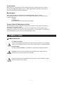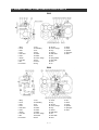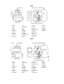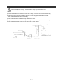
1
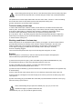
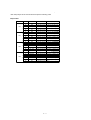
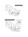
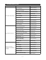
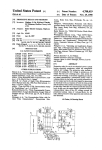
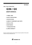
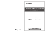
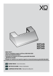
OM No.E-G07-01 0802
MIYAWAKI
BALL FLOAT STEAM TRAP
GH2 / GH4 / GH6 / GH8
USER'S MANUAL
1. SYMBOL USED
2. SAFETY INSTRUCTIONS
3. SPECIFICATIONS
4. NAMES OF
COMPONENTS AND PARTS
5. INSTALLATION
6. MAINTENANCE
7. TROUBLESHOOTING
8. LIMITED WARRANTY
Be sure to read this manual to learn the safe and proper operation of this product.
Store this manual carefully after use.
1 / 11
To the owner
Ball Float Steam Trap Model GH series is designed for large capacities with built in bi-metal
air vent and double ported balance valve. In order to get maximum benefit from this product,
be sure to read this manual before installing it.
Maintenance
If this product functions or looks abnormal, take the necessary steps to correct it.
If it seemingly cannot be corrected, ask your MIYAWAKI dealer what to do and give him the
following information.
(1) Model
(2) Serial (S)/ No.
(3) Detailed description of the abnormal condition.
Supply Period for Maintenance Parts
We will continue to supply maintenance parts for this product for 5 years after we discontinue
production of the primary product.
The supply of maintenance parts will, in principle, terminate at the end of the supply period
stated above. However, even after the supply period has run out, it is possible to consult with us
about the delivery time and prices for parts that are still in stock.
1 SYMBOLS USED
●SYMBOL INDICATION
!
(1) Safety-alert Symbol
This is the safety-alert symbol. When this symbol is on the machine or in this manual,
be alert to the possibility of personal injury and carefully read the messages that follow.
(2) Signal Words
The signal words "WARNING", "CAUTION" are used with the safety-alert symbol.
!
WARNING denotes an extreme hazard which will likely result in death or serious
personal injury if proper precautions are not taken.
WARNING
!
CAUTION denotes general precautions that may result in injury or damage to objects
if proper precautions are not taken.
CAUTION
2 / 11
2 SAFETY INSTRUCTIONS
Observe the following instructions to insure safe operation. If you don't, you may be seriously
injured and the product may be damaged.
* Be sure not to use this product at a pressure higher than the specified maximum operating
pressure (PMO) or at a temperature higher than the specified maximum operating
temperature (TMO).
* Pay very careful attention when working in hazardous environments such as:
There is a risk of explosion and the possibility of dangerous gasses leaking.
* Always check whether the pipeline contains flammable, high pressure or high temperature
materials before starting to work.
* Make sure that isolation valves are installed on both the upstream and downstream lines.
* Before installing the product, open the isolation valves, and the bypass valve, if one exists,
to blow out any debris or dust inside the pipeline.
* When installing the product, be sure to leave clearance for maintaining it.
* When replacing parts, make sure the replacement parts are supplied by MIYAWAKI.
3 SPECIFICATIONS
GH2
CONNECTION
MODEL NO.
TYPE
SIZE mm (inch)
GH4/GH6/GH8
BODY
MATERIAL
OPERATING
PRESSURE
MPa (psig)
MAX.
TEMP.
℃(°F)
25 (1")
32 (1-1/4")
GH2
40 (1-1/2")
50 (2")
GH4
Flanged
32 - 50
(1-1/4" - 2)
Cast Steel
(SCPH2)
0.01~2.0
(1.45~290)
400
(752)
DIMENSIONS mm (inch)
WEIGHT
kg (lb)
L
L1
H
H1
H2
200
(7.9)
200
(7.9)
200
(7.9)
210
(8.3)
310
(12.2)
235
(9.4)
83
(3.3)
65
(2.6)
24
(52.8)
200
(7.9)
380
(15.2)
320
(12.8)
105
(4.1)
90
(3.5)
43
(94.6)
GH6
40 - 80
(1-1/2 - 3)
270
(10.6)
415
(16.6)
345
(13.6)
130
(5.1)
90
(3.6)
68
(149.6)
GH8
80, 100
(3", 4")
350
(13.8)
590
(23.6)
470
(18.5)
174
(6.9)
120
(4.7)
162
(356.4)
Model
GH2
GH4
GH6
GH8
Dismounting Space
170mm
210mm
220mm
310mm
3 / 11
4 NAME OF THE COMPONENTS AND PARTS
GH2
1. Body
11. Nut
23. Air Vent
2. Cover
12. Guide Wing
24. Connec. Flange
44. Collar
3. Float
13. Pin
29. Plug
45. Split Pin
4. Lever
14. Bolt
31. Gasket
47. Spring Pin
5. Valve Seat
15. Gasket
32. Buffle Plate
50. Plate
6. Valve
16. Gasket
35. Nut
7. Holder
18. Connec. Flange
36. Spring Washer
8. Lever Nut
19. Bolt
37. Name Plate
9. Nut
21. Screen
38. Rivet
10. Connector
22. Plug
39. Pin
43. Shaft
GH4
1. Body
11. Nut
21. Screen
2. Cover
12. Guide Wing
22. Plug
43. Shaft
3. Float
13. Pin
23. Air Vent
44. Collar
4. Lever
14. Bolt
24. Connec. Flange
45. Split Pin
5. Valve Seat
15. Gasket
29. Plug
47. Spring Pin
6. Valve
16. Gasket
31. Gasket
50. Plate
7. Holder
17. Gasket
32. Buffle Plate
8. Lever Nut
18. Connec. Flange
35. Nut
9. Nut
19. Bolt, Nut
37. Name Plate
10. Connector
20. Bolt
38. Rivet
4 / 11
39. Pin
GH6
1. Body
11. Nut
21. Screen
43. Shaft
2. Cover
12. Guide Wing
22. Plug
44. Collar
3. Float
13. Pin
23. Air Vent
45. Split Pin
4. Lever
14. Bolt
24. Connec. Flange
47. Spring Pin
5. Valve Seat
15. Gasket
29. Plug
50. Plate
6. Valve
16. Gasket
31. Gasket
7. Holder
17. Gasket
32. Buffle Plate
8. Lever Nut
18. Connec. Flange
35. Nut
9. Nut
19. Bolt, Nut
37. Name Plate
10. Connector
20. Bolt
38. Rivet
GH8
1. Body
11. Nut
21. Screen
38. Rivet
2. Cover
12. Guide Wing
23. Air Vent
43. Shaft
3. Float
13. Pin
24. Connec. Flange
44. Collar
4. Lever
14. Bolt
29. Plug
45. Split Pin
5. Valve Seat
15. Gasket
31. Gasket
47. Spring Pin
6. Valve
16. Gasket
32. Buffle Plate
50. Plate
7. Holder
17. Gasket
33. Bolt, Nut
8. Lever Nut
18. Connec. Flange
34. Screen Cover
9. Nut
19. Bolt, Nut
35. Nut
10. Connector
20. Bolt
37. Name Plate
5 / 11
5 INSTALLATION
!
Before installing the product, open the isolation valves, and the bypass valve,
if one exists, to blow off any debris or dust inside the pipeline.
CAUTION
(1) Check the flow direction marked on the side of the body, and match with the arrow on the body.
(2) This trap is for a horizontal installation. Be sure to create a slight downhill gradient so that
the condensate will flow in and out smoothly.
(3) The product should be installed for easy maintenance check.
(4) Open the isolation valve on the primary line slowly and make sure the product works normally.
(5) The outlet line should be piped from the steam trap as shown below.
6 / 11
6 MAINTENANCE
!
When taking apart the trap from the line, close the both primary and secondary stop valve,
and cool down the trap itself first to avoid the danger of steam and condensate blowout.
WARNING
The performance of steam traps deteriorates over time due to wear, corrosion, or dirt accumlating
around the valve seat. To keep steam systems and equipment working well,
periodic maintenance of the steam traps is essential.
Tools for testing steam traps
In order to test steam traps, ultrasonic testers, sound detectors, and thermometers have been
used for years. These tools are relatively easy to use and are useful for making rough estimates
of the level of deterioration in a defective trap. However, to determine deterioration levels
and steam losses quantitatively, special tools are required for testing steam traps.
Dr. Trap and Dr. Trap Jr. are testing equipment that were developed specifically for diagnosing
steam traps and analyzing survey results automatically. Use these tools to avoid tiresome jobs
on sites and save working time.
Working conditions of a steam trap
Steam trap failures can be classified as either 'Leaking' or 'Plugged'. The level of steam leaks is
generally determined by the intensity of the ultrasonic vibration generated in the valve seat
inside of a steam trap. The 'plugged' is diagnosed by measuring the surface temperature.
As the degree of plugging increases due to a buildup of dirt in the trap, it will finally
become completely plugged.
Then the surface temperature will drop to around 40 degrees centigrade, or lower.
Repairs
When a trap fails, it is necessary to clean the internal parts and replace damaged parts.
Take the failed trap apart following the steps below.
(1) Remove the trap from the piping. Take off the Bolt (19) (model GH4/GH6/GH8: Nut (19))
and dismantle the Body (1), all the inner parts are fixed to the Cover (2).
(2) Take off the Bolt (14) with a wrench. The Valve Unit will be dimantled.
The Float (3) can also be dismantled with a wrench.
(3) Clean and inspect the Body (1) and the Valve Unit, if not defected assemble in the opposite way
of disassembling.
(4) If the Valve (6) and Valve Seat (5) are worn out or defected, replace the whole Valve Unit.
(5) If the Float (3) is damaged, loosen the Nut (35) of the Lever (4) and turn the Float (3) by hand
and replace it.
(6) Take off the Plug (22) (model GH8: take off the Nut (33) and dismantle the Screen Cover (34)),
take out Screen (21) and clean it.
!
CAUTION
When reassembling always replace the Gasket (15), (16), (31) to new ones.
Gaskets are fragile, so please handle with care.
Bolt (14), (19), (33) should be tightened evenly.
7 / 11
*The clamp torque of the screws will be as per the following chart.
Torque table
Model
GH2
GH4
GH6
GH8
No.
Parts
Size
Clamp Torque
14
Bolt
14 mm (0.55 inch)
30N・m (300 kgf ・cm)
19
Bolt
13 mm (0.51 inch)
50N・m (500 kgf ・cm)
22
Plug
46 mm (1.81 inch)
120 N・m (1,200 kgf ・cm)
23
A ir Vent
32 mm (1.26 inch)
130 N・m (1,300 kgf ・cm)
35
Nut
13 mm (0.51 inch)
14
Bolt
14 mm (0.55 inch)
19
Bolt, Nut
19 mm (0.75 inch)
40N・m (400 kgf ・cm)
60N・m (600 kgf ・cm)
20
Bolt
19 mm (0.75 inch)
80 N・m (800 kgf ・cm)
22
Plug
54 mm (2.13 inch)
150 N・m (1,500 kgf ・cm)
23
A ir Vent
32 mm (1.26 inch)
130 N・m (1,300 kgf ・cm)
35
Nut
13 mm (0.51 inch)
14
Bolt
19 mm (0.75 inch)
19
Bolt, Nut
19 mm (0.75 inch)
45N・m (450 kgf ・cm)
60N・m (600 kgf ・cm)
20
Bolt
24 mm (0.94 inch)
120 N・m (1,200 kgf ・cm)
22
Plug
60 mm (2.36 inch)
150 N・m (1,500 kgf ・cm)
23
A ir Vent
32 mm (1.26 inch)
130 N・m (1,300 kgf ・cm)
35
Nut
13 mm (0.51 inch)
14
Bolt
19 mm (0.75 inch)
80 N・m (800 kgf ・cm)
19
Bolt, Nut
24 mm (0.94 inch)
120 N・m (1,200 kgf ・cm)
20
Bolt
24 mm (0.94 inch)
120 N・m (1,200 kgf ・cm)
23
A ir Vent
32 mm (1.26 inch)
130 N・m (1,300 kgf ・cm)
33
Bolt, Nut
24 mm (0.94 inch)
120 N・m (1,200 kgf ・cm)
35
Nut
17 mm (0.67 inch)
8 / 11
29.Plug
37.Name Plate
Assembly Drawing Of Model GH2
1.Body
16.Gasket
3.Float
23.Air Vent
50.Plate
19.Bolt
21.Screen
31.Gasket
22.Plug
14.Bolt
Valve Unit
15.Gasket
2.Cover
Assembly Drawing Of Model GH4・GH6・GH8
Inlet Connection of Model GH8
29.Plug
2.Screen Cover
31.Gasket
37.Name Plate
21.Screen
1.Body
16.Gasket
33.Bolt, Nut
3.Float
23.Air Vent
18.Connection Flange
50.Plate
2.Cover
21.Screen
31.Gaske
22.Plug
14.Bolt
Valve Unit
15.Gasket
19.Bolt, Nut
18.Connection Flange
24.Connection Flange
20.Bolt
9 / 11
7 TROUBLESHOOTING
Problem
Steam leaks or blows through
Possible Causes
Solution
Stuck valve or dirt accumulated around
Valve or Valve Seat.
Clean the Valve Unit.
Stuck valve or dirt accumulated around
Guide Wing or Valve Seat.
Clean the Valve Unit.
Damage, wear or corrosion of Valve Unit.
Replace the Valve Unit.
Bolt (14) is loose.
Tighten the Bolt.
Air Vent is damaged.
Replace the Air Vent.
Air Vent is loose.
Tighten the Air Vent.
Gasket (15) is damaged.
Replace the Gasket.
Gasket (54) is damaged.
Replace the Gasket.
Improper installation.
Reinstall the product.
Bolt (19) or Nut (19) is loose.
Tighten the Bolt, Nut..
Gasket (16) is damaged.
Replace the Gasket.
Plug (22) is loose.
(Model GH2 / GH4 / GH6)
Tighten the Plug.
Bolt, Nut (33) is loose. (Model GH8)
Tighten the Nut.
Gasket (31) is damaged.
Replace the Gasket.
Bolt (20) is loose.
(Model GH4 / GH6 / GH8)
Tighten the Bolt.
Gasket (17) is damaged.
(Model GH4 / GH6 / GH8)
Replace the Gasket.
Plug (29) is loose.
Tighten the Plug.
Dirt has built up on or around the Valve or
Valve Seat.
Clean the Valve Unit.
Float is damaged.
Replace the Float.
Screen is clogged.
Clean the Screen.
Air Vent is damaged.
Replace the Air Vent.
Inlet valve is closed.
Open the Inlet Valve.
Insufficient condensate capacity.
Replace the trap with
a larger capacity.
Steam leaks from the body
Insufficient condensate
discharged, or no condensate
discharged
* See the torque table in Chapter 6.
10 / 11
8 LIMITED WARRANTY
Any trap that fails in normal operating conditions will be repaired free of charge.
WARRANTY TERM
This warranty term shall be for the first 12 months of ownership, starting from
the date of delivery to you.
WHAT THIS WARRANTY DOES NOT COVER
(1) Damage caused by careless use or ignoring the warnings and cautions given in this manual.
(2) Damage caused by severe shock or an impact which would not be experienced
in normal operation.
(3) Damage caused by unauthorized modifications or repairs.
(4) Damage caused by fire, natural disasters, or acts of God.
(5) Damage caused by inappropriate handling or installation in a way that
violates the specifications.
(6) Damage caused by equipment, apparatus or devices that are not provided by MIYAWAKI.
(7) Damage caused by chlorine, or other materials that are corrosive to metals or
hasten deterioration.
(8) Damage caused by a part such as a gasket that is severely deteriorated.
(9) Damage caused by accumulated dirt or debris on or around the seat.
WARRANTY SCOPE
In any event, the scope of the warranty is limited to compensation that does not exceed the
purchase price of the product.
11 / 11