1
FASSI CRANE
F 700A/800AXP.26
use and maintenance
FROM SERIAL NUMBER *1001*
INDEX
1
INTRODUCTION
2
2.1
2.2
2.3
CLASSIFICATION OF THE CRANE MODEL
Generality
Hydraulic jibs
Technical data
3
3.1
3.1.1
CAPACITY PLATES
Generality
Capacity plates with lifting moment limiting device
4
HYDRAULIC SCHEMATICS
5
ELECTRIC SCHEMATICS
6
SAFETY NORMS
7
7.1
7.2
7.3
7.4
7.5
WARNING AND INSTRUCTIONS
Generality
Before operating
During operation
At the end of the operation (Prior to driving the vehicle)
Residual risks
8
8.1
8.2
IDENTIFICATION OF THE CRANE MODEL
Generality
Crane mark
9
9.1
CRANE NOMENCLATURE
Controls for crane and outriggers through push-button panel of the radio remote control
10
10.1
NOMENCLATURE OF THE SAFETY AND PROTECTION DEVICES
Controls for crane and outriggers through push-button panel of the radio remote control
11
11.1
11.2
SUPPLEMENTARY BEAMS
Generality
Identification of the supplementary beams
12
12.1
TILTABLE OUTRIGGER RAMS
Manually tiltable outrigger rams
13
13.1
13.2
13.3
13.3.1
13.3.2
MANOEUVRES AND CONTROLS TO STABILIZE THE VEHICLE
Generality
Functions of control levers for stabilization
Controls to stabilize the vehicle
Crane with fixed or manually tiltable supports for outrigger rams
Crane with hydraulic tiltable supports (WITH CHAIN) for outrigger rams
Edition 22.07.2005
1
1
14
14.1
14.2
14.3
15
16
16.1
16.2
16.3
16.4
16.5
16.6
16.7
16.7.1
16.7.2
16.7.3
16.8
16.8.1
16.9
17
17.1
17.2
17.3
18
18.1
18.2
19
20
20.1
20.2
20.3
20.4
20.5
20.6
20.7
20.8
20.9
20.10
21
21.1
21.2
21.2.1
22
22.1
22.2
22.3
22.4
22.5
22.6
22.7
22.8
22.9
23
24
24.1
24.2
24.3
25
CONTROLS TO OPERATE THE CRANE
Generality
Manoeuvres to unfold the crane into a working condition
Manoeuvres to fold the crane into the rest condition
MANOEUVRES OF THE CRANE LOADS (version with load limiting device) (not available)
MANOEUVRES OF THE CRANE LOADS (version with lifting moment limiting device)
Generality
Lifting moment limiting device “ELECTRONIC”
Control panel
Load handling
Lifting moment limiting device for two working sectors
Rotation limiting device
In the case of the appearance of the signal “ALARM” on the display of the control panel or of
the radio remote control or in case of an electrical failure
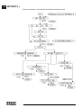
Diagnostic (Alarms/Input/Output) LME vers. 4-5 UC 01-7
Temporary OVERIDE-Reactivation for the crane functions in case of the appearance of the
signal “ALARM” on the display of the push-button panel
Temporary OVERIDE-Reactivation for the crane functions in case of an electrical failure, out
of order of the radio remote control, or of the appearance of the signal “ALARM” on the
display of the push-button panel (in this case, we cannot reactivate the crane functions)
XP device (if fitted, see the Use and Maintenance booklet)
Activation and instructions for use of the XP/V device
(if fitted, see the Use and Maintenance booklet)
IMC and ADC devices (if fitted, see the Use and Maintenance booklet)
USE OF IMPLEMENTS
Generality
Hydraulic connections for implements - supplementary hoses
Oil cooler (heat exchanger)
MANUAL EXTENSIONS
Generality
Lifting moment limiting device “ELECTRONIC” for the manual extensions
(valid starting from the version 3.0 of the software) (if fitted)
CONTROLS TO OPERATE THE HYDRAULIC IMPLEMENTS OF THE CRANE (not available)
HYDRAULIC JIBS
Generality
Identification of the hydraulic jib
Nomenclature of the hydraulic jib
Manoeuvres to unfold the jib in working condition
Manoeuvres to fold the jib in rest condition
Operations to remove the hydraulic jib from the crane
Operations to mount the hydraulic jib on the crane
Hydraulic jib articulated at 25 degrees with the automatic control (L515-L516)
Use of the hydraulic jib articulated at 25 degrees (not available on the L102 and on the L515-L516)
Crane with lifting moment limiting device and "pro link" (if fitted)
WINCH (if fitted)
Generality
Winch for crane
Winches equipped with a mechanical stroke end device
MAINTENANCE INSTRUCTIONS
Generality
Timer
After every 8 working hours or at the end of every working day
After every 40 working hours or atfter every working week
After every 100 working hours or more frequently in case of more intensive utilisation
After every 500 working hours or after every 6 working months
After every 1000 working hours or after every working year
Complete overhaul of the crane is required when 10.000 working hours or 10 years'life
are reached
Instructions for the dismantlement and the demolition of a FASSI crane
TABLE OF HYDRAULIC OIL AND LUBRICANTS CHARACTERISTICS
POSSIBLE FAULTS
Generality
Only operations which can be carried out by the user
Operations to be carried out only by a service center
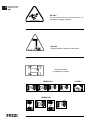
INSTRUCTION AND WARNING PLATES
FASSI CRANE
use and maintenance
ORIGINAL INSTRUCTIONS
THANK YOU FOR SELECTING ONE OF FASSI CRANES.
This crane is the result of FASSI philosophy: ongoing research, rigorous
testing, data verification, and analysis of performances.
Many years of experience has allowed us to grant you the maximum safety of
operation together with the optimization of machine performances.
All this represents the core of FASSI quality system.
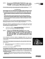
FASSI quality system is in conformity with
UNI EN ISO 9001:2000 (ISO 9001:2000)
FASSI cranes conform with the European Norm EN12999
The fitment of the crane on the vehicle must be carried out in accordance with
the instructions given by FASSI in the manual for hydraulic crane fitting and
the relevant chassis manufacturers directives.
The Manufacturer declines all responsibility and guarantee if the fitting is
entrusted to workshops without sufficient technical capability to carry out the
work in conformity.
Be sure that the unit has been installed, inspected and tested in accordance
with the local legal requirements.
As well as the principal safety norms, this manual contains a description of the
crane and the instructions for use and maintenance.
The following instructions refer to mobile cranes in general and must be integrated with the manual for use supplied by the centre responsible for the crane
fitting on truck, vehicle or other type of structure.
READ THIS MANUAL CAREFULLY prior to use or any maintenance. A few
minutes spent now could save time and labour later.
Always conform to the safety norms and the instructions for use and maintenance contained in the present manual in order to guarantee a long life to the
crane.
NOTE
The original version of the present manual is in italian.
The spare parts catalogue for the crane can be viewed in the Internet
site: www.fassicat.com
INDEX
GRU FASSI
1
2
CLASSIFICATION OF THE CRANE MODEL
2.1
CLASSIFICATION OF
THE CRANE MODEL
F 700A/800AXP.26
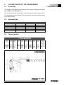
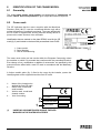
Generality
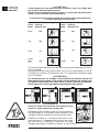
The design of this crane has been carried out in respect of fatigue test classification H1B3 of the EN12999 norm.
The crane can operate, intermittently, with lifting devices other than the hook.
The dimensions and the capacity of the implements must be proportioned with
crane performances.
2.2
Hydraulic jibs
Extension type
L414
L505
L506
L515
L516
2.3
Hydraulic jibs
Weight=kg Manual
Weight=kg Manual
850
--------------------PL41
1100
QL50
80
RL50
1240
QL50
80
RL50
1250
QL51
80
RL51
1400
QL51
80
RL51
Weight=kg
32
36
36
36
36
Manual
QL41
SL50
SL50
SL51
SL51
Weight=kg
22
25
25
25
25
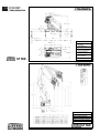
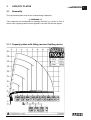
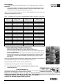
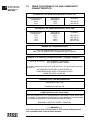
Technical data
F 700A/800AXP.26
Lifting
capacity
Standard
reach
Hydraulic
extension
Rotation
arc
Rotation
torque
Working
pressure
Pump
capacity
Oil tank
capacity
Crane
weight
Max. working
pressure
on the outrigger
(Φ 210)
66,3 tm
650,40 kNm
479.549
lbf.ft
16,15 m
11,80 m
360°
continuous
33,0 MPa
6715 kg
71,0 daN\cm2
38’8”
ft/in
80/100
l/min
21,13/26,42
gal/min
250 l
52’11”
ft/in
9,17 tm
90 kNm
66.327
lbs.ft
66,04
gals
14.804
lbs
1029,77 psi
4.786
psi
ST 700
2
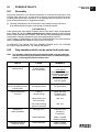
2.2
CLASSIFICATION OF
THE CRANE MODEL
F 700A/800AXP.26
— MEZZERIA TIRANTI
— FIXING ROD CENTER
DISTANCE
— LIGNE MEDIANE
TIRANTS
— ABMESSUNG DER
BEFESTIGUNGSBRIDEN
— DISTANCIA ENTRE
ESPÁRRAGOS
— LINHA MEDIANA
DOS TIRANTES
ST 700
M39 x 3
MASSIMA ALTEZZA SOTTOGANCIO.
HAUTEUR MAXIMUM SOUS CROCHET.
MAXIMUM HOOKING POSITION.
MAXIMALHOEHE BIS KRANHAKEN.
MÁXIMA ALTURA DEBAJO DEL GANCHO.
ALTURA LIVRE MÁXIMA DEBAIXO DO GANCHO.
ST 700
3
CAPACITY PLATES
3.1
Generality
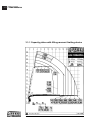
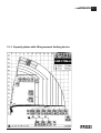
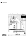
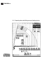
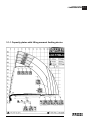
The represented plates refer to the nominal design capacities.
(!) WARNING (!)
If the capacities are downgraded or partially reduced (e.g. sector in front of
vehicle cab) capacity plates must be applied in line with the final test figures.
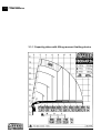
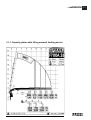
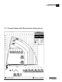
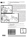
3.1-1 Capacity plates with lifting moment limiting device
CAPACITY PLATES
F 700A/800AXP.26
3
3.1-1
CAPACITY PLATES
F 700A/800AXP.26
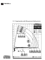
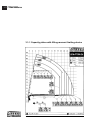
3.1-1 Capacity plates with lifting moment limiting device
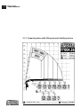
CAPACITY PLATES
F 700A/800AXP.26
3.1-1 Capacity plates with lifting moment limiting device
3.1-1
3.1-1
CAPACITY PLATES
F 700A/800AXP.26
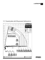
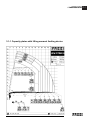
3.1-1 Capacity plates with lifting moment limiting device
CAPACITY PLATES
F 700A/800AXP.26
3.1-1 Capacity plates with lifting moment limiting device
3.1-1
3.1-1
CAPACITY PLATES
F 700A/800AXP.26
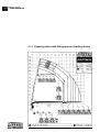
3.1-1 Capacity plates with lifting moment limiting device
CAPACITY PLATES
F 700A/800AXP.26
3.1-1 Capacity plates with lifting moment limiting device
3.1-1
3.1-1
CAPACITY PLATES
F 700A/800AXP.26
3.1-1 Capacity plates with lifting moment limiting device
CAPACITY PLATES
F 700A/800AXP.26
3.1-1 Capacity plates with lifting moment limiting device
3.1-1
3.1-1
CAPACITY PLATES
F 700A/800AXP.26
3.1-1 Capacity plates with lifting moment limiting device
CAPACITY PLATES
F 700A/800AXP.26
3.1-1 Capacity plates with lifting moment limiting device
3.1-1
3.1-1
CAPACITY PLATES
F 700A/800AXP.26
3.1-1 Capacity plates with lifting moment limiting device
CAPACITY PLATES
F 700A/800AXP.26
3.1-1 Capacity plates with lifting moment limiting device
3.1-1
3.1-1
CAPACITY PLATES
F 700A/800AXP.26
3.1-1 Capacity plates with lifting moment limiting device
CAPACITY PLATES
F 700A/800AXP.26
3.1-1 Capacity plates with lifting moment limiting device
3.1-1
3.1-1
CAPACITY PLATES
F 700A/800AXP.26
3.1-1 Capacity plates with lifting moment limiting device
CAPACITY PLATES
F 700A/800AXP.26
3.1-1 Capacity plates with lifting moment limiting device
3.1-1
3.1-1
CAPACITY PLATES
F 700A/800AXP.26
3.1-1 Capacity plates with lifting moment limiting device
CAPACITY PLATES
F 700A/800AXP.26
3.1-1 Capacity plates with lifting moment limiting device
3.1-1
4
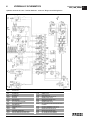
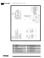
HYDRAULIC SCHEMATICS
HYDRAULIC SCHEMATICS
GR5_700_800XP
Hydraulic schematic for crane - Danfoss distributor - “electronic” lifting moment limiting device
CODE
DESCRIPTION
DI776
DI778
DV018
DV019
EV124
EV125
FI782
FI854
MT141
PR103
RU976
RU978
TR002
VA148
VA149
DISTRIBUTOR
DISTRIBUTOR
DEVIATOR
DEVIATOR
ELECTROVALVE
ELECTROVALVE
OIL FILTER (HIGH PRESSURE)
OIL FILTER (RETURN)
MOTOREDUCER
PRESSURE SWITCH
FAUCET
FAUCET
PRESSURE TRANSDUCER
ELECTRIC MAIN WITH BY PASS VALVE
ELECTRIC MAIN WITH BY PASS VALVE
VA184
VA185
VA194
VA232
VA239
VA246
VA249
VA256
VA259
VA260
VA263
VA262
SC002
SC001
SENSOR VALVE
SELECTOR VALVE
DOUBLE EFFECT BLOCK VALVE
UNIDIRECTIONAL VALVE
SIMPLE EFFECT BLOCK VALVE
REGENERATIVE VALVE
UNIDIRECTIONAL VALVE
OIL FLOW REGULATOR VALVE FOR ROTATION
CYLINDER
ELECTRIC REGENERATIVE VALVE 24V
ELECTRIC REGENERATIVE VALVE 12V
DOUBLE EFFECT BLOCK VALVE
SIMPLE EFFECT BLOCK VALVE
OIL COOLER (HEAT EXCHANGER)
OIL COOLER (HEAT EXCHANGER)
4
4
HYDRAULIC SCHEMATICS
Hydraulic schematic for crane - versions
GR5_700_800XP
CODE
DESCRIPTION
DI776
DI778
DV018
DV019
FI782
FI854
NI1006
RU976
SC002
SC001
DISTRIBUTOR
DISTRIBUTOR
DEVIATOR
DEVIATOR
OIL FILTER (HIGH PRESSURE)
OIL FILTER (RETURN)
SPECIAL STRAIGHT PIPE FITTING M
FAUCET
OIL COOLER (HEAT EXCHANGER)
OIL COOLER (HEAT EXCHANGER)
TR001
VA164
VA175
VA185
VA187
VA200
VA215
VA232
VA246
VA249
PRESSURE TRANSDUCER
DOUBLE EFFECT BLOCK VALVE
BLOCK VALVE + FAUCET
SELECTOR VALVE
BLOCK VALVE + FAUCET
DOUBLE EFFECT BLOCK VALVE
OIL FLOW CHECK VALVE
UNIDIRECTIONAL VALVE
REGENERATIVE VALVE
UNIDIRECTIONAL VALVE
5
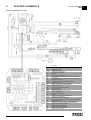
ELECTRIC SCHEMATICS
ELECTRIC SCHEMATICS
GR5
Electric schematic for crane
N°
DESCRIPTION
ALIM
ALIM1
ALIM2
D1\...\D10
DR
EM
EV1
EV2
EV3
EV4
EV5
EVDEV
EVE1/2/3/4
EVG
EVR
EVS1/2/3/4
EVU
FX003
FX004
IP1/2/3
LCV
LG
LP
LR
M1/…/M7
MS
MV1
MV2
P1
S25
RADIO
TP1
TP2
TP3
UCF
GENERAL FEEDING
SHUNT BOX ON THE COLUMN
SHUNT BOX ON THE BASE
CONNECTORS FOR DANFOSS MODULUS
ELECTRIC ROTATING DISTRIBUTOR
EMERGENCY
ELECTROVALVE FOR CRANE BLOCK
ELECTROVALVE FOR LIFTING MOMENT LIMITING DEVICE OF THE TWO WORKING ZONES
XP ELECTROVALVE
ELECTROVALVE FOR PRESSURE REDUCTION OF REGENERATIVE EXTENSION EXIT
REGENERATIVE ELECTROVALVE
ELECTROVALVE FOR ELECTRIC DEVIATOR CRANE/OUTRIGGERS
EXTENSION ELECTROVALVE
GENERAL ELECTROVALVE FOR OUTRIGGER DISTRIBUTOR
RE-ENTRY ELECTROVALVE OUTRIGGERS/EXTENSIONS
OUTRIGGER ELECTROVALVE
EXIT ELECTROVALVE OUTRIGGERS/EXTENSIONS
DANFOSS CONTROL UNIT
OUTRIGGER CONTROL UNIT
PROXIMITY MICROSWITCH FOR ROTATION CONTROL
WINCH LOAD LIMITING DEVICE
90% LOAD YELLOW WARNING LIGHT
FLASHING
ACTIVATION OF OVERLOAD BLOCK RED WARNING LIGHT
MICROSWITCH ON THE DISTRIBUTOR
MERCURY LEVEL SENSOR ON THE OUTER BOOM
PULLEY MICROSWITCH FOR WINCH (FITTED ONLY ON THE ELECTRIC STROKE END)
DRUM MICROSWITCH WINCH
PRESSURE SWITCH FOR THE RE-ENTRY OF THE EXTENSION BOOMS
SELECTOR FOR ACTIVATING SECOND MS FOR THE HYDRAULIC JIB AT 25°
RECEIVER OF THE RADIO REMOTE CONTROL
PRESSURE TRANSDUCER FOR INNER RAM
PRESSURE TRANSDUCER FOR OUTER RAM
PRESSURE TRANSDUCER FOR THE JIB RAM
GENERAL CONTROL PANEL (FX000)
5
6
SAFETY NORMS
SAFETY NORMS
GR2_3_4_5
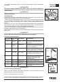
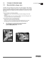
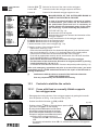
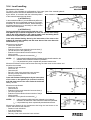
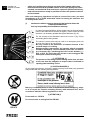
Strictly conform to the norms reported by the plates DE2499B (fig. 1) or
DE4236 (fig. 1a) placed next to the controls, in order to avoid possible accidents while operating the crane.
Only authorized persons are allowed to operate the crane.
The crane must be used on firm, level ground.
Check that the vehicle hand brake is on and that the wheels are chocked.
Before every operation make sure that:
- no-one is within the working area of the crane;
- the safety devices are in place and operative;
- the minimum safe working distances from power lines are observed;
- the load is correctly slung and hooked.
Stabilize the vehicle by the outrigger rams, making
sure that:
- the lateral supports are fully extended;
- the wheels are in contact with the ground and the
suspension is not completely unloaded.
VERTICAL VERSION
fig. 1
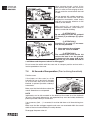
Use the crane in accordance with the use and maintenance
manual, making sure that:
- the load and radius are within the maximum limits
shown on the crane capacity plate;
- the crane is used progressively avoiding sudden
load movements
- swinging or dragging of the load is avoided;
- the load is lifted before rotating.
When using implements protect the crane working area
with a barrier.
The vehicle/crane are not left unless the power take off
is disengaged and the load is on the ground.
Before driving the vehicle make sure that the outriggers
are fully retracted and re-entered, the safety taps closed and the crane is in folded position.
HORIZONTAL VERSION
fig. 1a
6
7
WARNING AND INSTRUCTIONS
7.1
Generality
The use of the crane is reserved to authorized personnel, instructed in advance,
who has to conform to the safety norms and instructions contained in the use
manual supplied with the crane. (See norms ISO 9926-1)
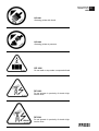
It is absolutely prohibited to walk or stop under a suspended load
It is prohibited for unauthorized persons to be within the working area.
Under no circumstances interfere with the safety and protection devices.
Warning plates, as well as instruction and operation plates must be replaced when
no longer readable or missing. See Paragraph 25 Instruction and warning plates.
Do not use the outriggers to raise the vehicle.
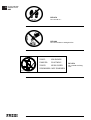
To avoid hitting bridges or tunnels check and record the overall height of your crane
in the folded position or in laid position in the body or on the load. Always respect
and pay proper attention to road signs placed in proximity of such obstacles.
7.2
Before operating
(!) ATTENTION (!)
Check that protections are in their place and that all safety devices are fitted
and active. (See norms ISO 9927-1)
Keep the ladder and the control station on the top seat, clean; normally, the seat
can tilt forward.
Make sure that control stations are properly lit so as to ensure safety while operating and allow instruction plates to be visible.
Check that the working area is adequate and properly lighted for your crane.
Make sure that the hook is always free to rotate on its pin and that nothing
obstructs its vertical positioning.
Check the efficiency of the hook safety catch.
Carefully inspect the condition of ropes or chains (if present)
Make sure that the pallet fork (if present) is connected to the crane hook by
means of a chain having at least three (3) rings.
7.3
During operation
Take the vehicle fumes away from the working area by fitting an extension tube of
a suitable diameter and a right length to the exhaust system.
Do not run the engine in a indoor area without first making sure there is adequate
ventilation.
When using the ladder to reach the control station on the top seat, avoid knocking
into the controls while going up or down the ladder.
The control station on the top seat is provided with side safety guards; stay within
these guards.
Make sure that no one is within the working area of the crane.
SAFETY NORMS
GRU FASSI
7
7.3
WARNING AND
INSTRUCTIONS
GRU FASSI
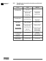
(!) ATTENTION (!)
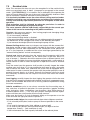
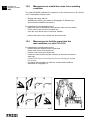
Avoid swinging the load above working and transit areas; any hidden danger situation must be audibly alarmed.
Avoid all those situations which may result in crushing during vehicle stabilization, crane movement and load handling.
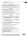
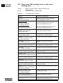
(In conformity with EN 349 standard the minimum safe working distances
to avoid crushing parts of the body)
Parts
of the
Body
Minimum safe
working
distance mm
Figure
Parts
of the
Body
Minimum safe
working
distance mm
Body
500
Head
300
Leg
180
Foot
120
Toes
50
Arm
120
Hand
Wrist
Fist
100
Finger
25
Figure
The table indicates the minimum safety working distances concerning the various
parts of the body.
The figures illustrate circumstances which may turn out to be dangerous if you fail
to respect the minimum safe distances and if it is impossible to introduce larger
parts of the body.
(!) ATTENTION (!)
For designated areas as: outrigger running towards rest position, leaning and
folding points of the booms in rest position, control platform and swinnig column, top seat and running inner boom, where no carter is possible to be placed,
please observe the shear and trapping hazard stickers nearly placed.
(!) ATTENTION (!)
Failure to respect the minimum safe distances may
result in a safety hazard and a deadly risk.
Remember that the stability of the unit (crane-vehicle) is
only guaranteed by the complete lateral extension of the
outriggers and by the observance of the capacity plates.
Stabilize the vehicle on a horizontal plane with a maximum tolerance of 1,5 degrees. Make sure that the outrigger rams rest on a solid base, if necessary use larger
outrigger base plates (available on request) to avoid sinking.
If you adopt other means, make sure that they are suitably sized for the load they
must bear.
(!) ATTENTION (!)
Respect the safety distances from electric lines; the minimum distance is,
according to CEN norms, five (5) meters, except for otherwise prescribed by
national norms.
(!) ATTENTION (!)
Failure to respect the minimum safe distances may result in electrical hazards for the operator and his assistants.
ELECTRICUTION:
General safety precautions for the operator and potential co-workers. If the crane hits an overhead power line, do not touch the crane, the truck or the load.
Carefully evaluate the danger before moving. If you are closer than 10 meters from the crane,
the truck, the load or the electric line, move at least 10 meters away, by shuffling away with
small steps, in order to minimize the chance of getting a too high voltage difference between
the feet.
Warn others to stay away; call for help and contact the power company to de-energize the line:
do not attempt to assist someone in direct or indirect contact with the power line before the
power has been disabled: you run the risk of being electricuted yourself.
If you are in the truck cabin, stay inside without touching the vehicle body because it's extremely
hazardous to go out before the line is de-energised.
Help the electricuted person if you know the first-aid procedures, otherwise wait for the paramedics to arrive.
(!) ATTENTION (!)
Do not utilize the crane during thunderstorms and with wind speed exceeding
13,8 m\s (50 km/h), maximum value of the Beaufort scale degree 6.
Indications about wind speed
Force of the wind Wind speed
Beaufort scale
m/s
Classification
Characteristics
0
0,0 - 0,2
Calm
Calm wind, smoke goes up quite
vertically
1
2
0,3 - 1,5
1,6 - 3,3
Light breeze
Smoke reveals the direction of the
wind, one can feel the wind blowing,
leaves start fluttering.
3
4
3,4 - 5,4
5,5 - 7,9
Moderate breeze
5
8,0 - 10,7
Fresh breeze
Leaves and branches are in constant
motion, small branches start fluttering.
Dust and papers dance on the ground.
.
Small green branches bend, the surface
of waterways and lakes are wavy.
6
10,8 - 13,8
Near gale
Big branches bend, wind whistles
through high-tension cables, it's
difficult to walk keeping the
umbrella open.
7
13,9 - 17,1
Moderate gale
Trees sway, it's hard to walk
8
17,2 - 20,7
Storm wind
Branches get broken, it's hard to walk.
9
20,8 - 24,4
Storm
It damages houses(antennas and roof
tiles fall down )
(!) ATTENTION (!)
Carefully inspect the load rigging.
Hook up the load, checking that it does not exceed the capacity indicated on the lifting
diagram specific to each load configuration.
Make sure that the lifted load is balanced.
Avoid swinging the load above the control station; in cases where the load is too close,
the crane must be operated from the opposite side or with the radio-remote control.
WARNING AND
INSTRUCTIONS
GRU FASSI
7.3
7.4
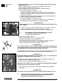
When operating through a winch, lift the
load vertically using the cable and not the
booms in order to avoid swinging the load.
Do not rotate the crane before the load
is lifted.
WARNING AND
INSTRUCTIONS
GRU FASSI
Do not operate with sudden movements, activate the controls with slow and
progressive movements; rotate slowly
and with care paying attention to the
stability of the vehicle.
With vertical lift, on hydraulic and
mechanical extension, rotate slowly in
order to avoid side-skidding.
(!) ATTENTION (!)
Do not utilize the crane for pushpull
(F), lateral (F) or sideways (F) operations.
(!) ATTENTION (!)
Crushing (F) or push (F) ma-noeuvres are not permitted.
(!) Never operate the outriggers
when the crane is loaded.
(!) ATTENTION (!)
The vehicle\crane must not be left
unless the load is on the ground,
the booms of the crane (and of the
hydraulic jib), are folded and laid on
a solid base and the power take-off is disengaged.
Do not move the vehicle with the crane not in transport position and not with a
load suspended on the crane.
7.4
At the end of the operation (Prior to driving the vehicle)
Fold the crane.
If the booms of the crane (or of the
hydraulic jib) are to be laid on the body
or on the load, they must be suitably
blocked to prevent possible sideways
movements.
Make sure that the indications about the
overall dimensions are respected.
NOTE
Implements can be left mounted on the booms of the crane (or of the hydraulic
jib) only if the overall dimensions are respected; they must be suitably blocked to
prevent possible sideways movements.
If an accessory (fork, ...) is mounted, it must be tied down at all times during transport.
Make sure that the outrigger supports and rams are re-entered within the overall
width of the truck and locked by the safety devices.
Disengage the power take off.
7.5
Residual risks
Note: This reasoned list does not carry the complete list of the residual risks,
which are examined more in detail paragraph by paragraph in the manual
under "(!) ATTENTION (!)"; it is instead a way to exemplify to the operator the
types of hazards linked to the use of the crane, which basically involves a lifted
load in movement. Therefore we confirm you the following
It is absolutely forbidden to use the crane without having read and understood the manual for use and maintenance and without having being previously instructed by experienced personnel on all aspects of safe crane
operation.
Risk evaluation shall be followed by adequate provisions in order to
avoid risks and damages to people and things.
The crane operator shall be held directly responsible for the correct operation of the crane also according to the jobsite conditions.
Overturn: the crane can overturn, thus hurting people and damaging things
specially in following conditions:
- if it is not correctly stabilized
- if the moment limiting device is disabled
- if the ground conditions at the jobsite are not stable enough with respect to
the dimensions of the outrigger base and/or of the additional base plate
- if you increase the design dynamic increasing the pump oil flow.
Moment limiting device: never try to bypass nor tamper with the moment limiting device and the various safety systems installed on the crane. In such case
the operator shall be held responsible for the subsequent crane performance. It is also important to understand the alarm messages generated by the
"moment limiting device" and act consequently.
Control seat: before operating from the control seat the operator shall make
sure that he's safe from hazards (i.e. he stands clear of the load, there is a
way of escape,..). Otherwise he shall manoeuvre from a different control seat;
if there is none available, the crane should be equipped with a radio control or
remote control in order to allow the operator to operate the crane in absolute
safety.
From the control seat the operator shall be able to visually inspect the whole
working area at all times. If it is not possible he shall team up with a co-worker
able to control the whole area; otherwise the crane shall be equipped with a
radio control in order to ensure the operator with the perfect position to see all
potential hazards clearly at all times. Naturally the operator shall also teach
this eventually co-worker with the scope of not harm each other with control
commands.
Load rigging: carefully inspect the load rigging; the operator shall make sure
that the load is properly attached and balanced and that all unexpected movements are not allowed. Be careful not to hit any potential impediments during
the crane movements.
Jobsite conditions: prior to use always ascertain that the working area is
free and clear of potential obstacles to crane operations (people, building
walls, balconies, eaves, scaffoldings, tree branches, other lifting means or
machines,electric lines,…). This may hurt people, damage both the impediments and the crane, and provoke also the crane overturn.
Make sure that there is no risk of elements falling on the operator or on the
crane and take the right precautions to prevent it.
Overload and/or fatigue: the crane can break down due to fatigue or overload:
- If it is misused (with cycles, loads or pump oil flow not pertinent to the crane
class)
- If it is used for improper tasks (side, oblique or reversal pull)
- If it is used in poor jobsites (corrosive environment, too high or too low
temperature, foundry,… [see conditions of use])
- If the load exceeds the rated capacity indicated on the relevant plates
WARNING AND
INSTRUCTIONS
GRU FASSI
7.5
7.5
WARNING AND
INSTRUCTIONS
GRU FASSI
Wrong manoeuvring: the crane can fall break or overturn if the operator
performs a wrong manoeuvre due to the lack of familiarity with the operation procedures (see manual of use and maintenance) or due to inadequate
psychophysical conditions: we remind you that the directives in force impose
a suitable training of the personnel before using these types of machines and
require an adequate psychophysical condition to operate safely a lifting device
that always implies the intrinsic danger of a lifted load.
Weather conditions: too high or too low temperatures may damage the components of the oleodynamic and electric circuits (See max and min conditions
of use); it is forbidden to operate the crane during a storm with lightning hazards, so we recommend to fold it and put it to rest. Furthermore when the wind is
too strong the crane can overturn or break down.
Shearing, entrapment: the crane has a lot of parts in movement that it is
impossible to cover; therefore the operator shall always be aware of this residual risk and keep clear from the parts in movement, particularly from the load;
the operator is held responsible not only for himself but also for those working
in proximity of the crane and for those who may draw closer even if not authorized.
Electricution: the crane is not insulated from electric contacts and therefore it is not equipped to work under tension, even if the contact is accidental.
Therefore be compliant with the min clearance prescribed by the national
directives in force. Generally speaking the clearance from electric lines with a
max tension of 38.000 volts should be at least 5 meters: Higher tensions require higher clearance to be verified case by case together with competent technicians and with respect to the environment conditions.
Manual extension overload: manual extensions are controlled by the moment
limiting device only under the conditions described in the relative chapter; the
control system of the manual extension overload must be activated by the operator as described.
Accessories: be careful when assembling and disassembling the accessories
(extensions, buckets, baskets,…); first verify the weight, the securing systems
and the instructions for assembly and dismantlement; then appraise their
barycentre and provide for adequate provisional blocking systems in order to
avoid sudden movements.
(!) ATTENTION (!)
If in the folding condition the hook is out of truck size, it must be taken
away before travelling.
Breakdown of some sensors
The system "moment limiting device - intelligent type" is always monitored
during ignition (the system, after having activated the various circuits, checks
the presence of all the inputs for around 4 seconds) and then continuously
monitors the operation and the efficiency of the limiting device (approx. every
25 milliseconds).
For most of the components the system checks also the congruence of the
incoming signal with the one the system expects.
Maintenance: maintenance is particularly important; the lack of it may damage
things or hurt people.
Particular operations: if you are required to operate under particular conditions
not illustrated in the manual of use and maintenance, analyse carefully the situation and always refer to an authorised Fassi shop or to the Fassi technical support service or to experienced operators before starting working.
8
IDENTIFICATION OF THE CRANE MODEL
8.1
Generality
IDENTIFICATION OF
THE CRANE MODEL
GRU FASSI
8
The exact crane model, serial number and description of implements will
enable FASSI Service Department to give a rapid and efficient response.
8.2
Crane mark
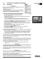
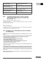
The CE indicates that the crane complies with the Machines
Directive (D.M.) 98/37; it can be considered effective only with a
written declaration of conformity enclosed. The crane affixed with
the CE mark is supplied with a lifting moment limiting device to
preserve the crane structure from overloads.
1
Identification data are marked on the plate DE5891 used for the CE
mark (fig. 2) and rivetted on the base with personalized rivets FASSI.
2
3
1 - Crane model
2 - Serial Number
3 - Year of manufacturing
fig. 2
The crane must not be put into service within the European Community unless
the machine on which it is mounted also conforms with the prescribed Directive.
Ever change of use, modification or addition of accessories, not specified by this
manual must be affixed with a new CE mark in accordance with the Machinery
Directive.
A further metallic plate (fig. 3) fixed to the crane by the installer, quotes the
identifying data of the equipment and the final CE mark.
1234-
Name of the installer who
applied the final CE mark
Crane mark, model and
serial number
Vehicle mark, model and
chassis number
Year of mounting
1
2
3
4
CRANE - MARK AND MODEL
SERIAL NUMBER
TRUCK - MARK AND MODEL
TRUCK FRAME SERIAL NUMBER
YEAR OF MOUNTING
fig. 3
(!)
UNDER NO CIRCUMSTANCES SHOULD THE DATA
MARKED ON THE PLATES BE ALTERED.
9
CRANE NOMENCLATURE
9.1
CRANE
NOMENCLATURE
GR5
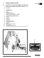
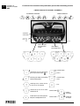
Controls for crane and outriggers through pushbutton panel of the radio remote control. (fig. 4).
Pos
Description
1.
2.
3.
4.
5.
6.
7.
8.
9.
10.
11.
12.
13.
14.
15.
16.
17.
18.
19.
20.
21.
22.
Outrigger rams
Outrigger supports
Base
Slew ring
Rotation motoreducer
Deviator crane - outriggers
Dual control for deviator crane - outriggers
Integrated group for outrigger controls
Electric hydraulic distributor for crane
Column
Inner ram
Inner boom
Outer ram
Outer boom
Booms extension rams
Extension boom sections
Lifting hook
Oil tank
Manual extensions (optional)
Heat exchanger
Receive radio remote control
Push-button panel (transmitting-console of the radio remote control)
22
fig. 4
9
10
NOMENCLATURE OF
THE SAFETY AND
PROTECTION DEVICES
10
NOMENCLATURE OF THE SAFETY AND
PROTECTION DEVICES
10.1
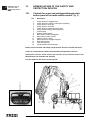
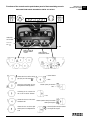
Controls for crane and outriggers through pushbutton panel of the radio remote control. (fig. 5).
GR5
Pos
1.
2.
3.
4.
5.
6.
7.
8.
9.
10.
11.
12.
13.
14.
15.
Description
Check valves for outrigger rams
Check valves for rotation control (flow regulators)
Check valve for inner ram
Check valve for outer ram
Check valve for booms extension rams
Lifting moment limiting device assembly
Control panel
Rotation limiting device
Main pressure valve (outriggers)
Main pressure valve (crane)
Auxiliary valves (crane)
Safety device for outrigger supports
Hook safety device
Exclusion tap lever
Visual indicator yellow/red light
Before crane use check that safety and protection devices are fitted and active.
Under no circumstances interfere with the safety and protection devices.
Interference with the check valves and removal of the lead seal remove the
Manufacturer and invalidate the warranty.
Use the ladder for the access to the top seat.
7
fig. 5
11
SUPPLEMENTARY BEAMS
SUPPLEMENTARY BEAMS
GR5_700_800XP
11.1 Generality
Supplementary beams are used in conjunction with the crane outriggers to
ensure the vehicle stability during load handling.
Code
750B055
750B054
outrigger ram
stroke mm
520
340
outrigger
interaxis mm
5770
5770
extension
Weight
type
kg
Hydraulic-“H” variable
840
Hydraulic-“H” variable
810
11.2 Identification of the supplementary beams
Identification data of the supplementary beam is punched on the beam (fig. 6) in
the following sequence:
Ex.
*750B055*0001
serial no.
identification code
fig. 6
11
12
TILTABLE OUTRIGGER RAMS
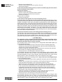
12.1
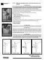
Manually tiltable outrigger rams
Outrigger rams are allowed to be stored in an inclined position, when obstructions on the vehicle chassis prevent their vertical stowability. These hinged
supports are placed between the outrigger supports and the rams; the fixed
part is screwed to the supports while the mobile part is screwed to the rams.
(fig. 9-9a)
To place the rams in a working condition.
- Supporting the ram, remove the check pin and the locking pin from their
positions.
- Position, carefully, the ram in working condition, insert the locking pin in its
new position and secure it with the check pin.
To re-position the rams to the folded position.
- Remove the check pin and the locking pin.
- Position, the ram in a upward direction and supporting the ram, insert
- the locking pin in its new position and secure it with the check pin
(!)
fig. 9
The locking pin is constructed from special material
- do not replace it with a non original part
- your security depends on it
fig. 9a
SUPPLEMENTARY BEAMS
GR5
12
13
13.1
MANOEUVRES AND CONTROLS TO STABILIZE
THE VEHICLE
SUPPLEMENTARY
BEAMS
GRU FASSI
Generality
The outriggers rams prevent damaging stresses both to the frame and to the
vehicle suspensions on which the crane is mounted to and assure the stability
of the unit during load handling.
Be very careful when stabilizing the vehicle; make sure that no one is or
transits in close proximity of the working area of the outriggers.
(!) ATTENTION (!)
The crane stability is maintained by the maximum extension of the
outrigger supports, by the solidity of the base underneath the plates of
the outrigger rams and by the observance of the capacity plates. To
check the maximum working pressure see Paragraph 2.3 Technical data
Check that the outrigger rams are applied on a solid base; if necessary use
larger outrigger base plates (available on request) to avoid sinking.
When stabilization is complete the wheels of the vehicle must still be in contact
with the ground and the suspensions must not be fully unloaded.
Stabilize the crane so as to operate on a horizontal plane with a maximum tolerance of 1,5 degrees.
While loading, it may be necessary to vertically adjust the outrigger rams to prevent an overload on the outriggers, then stabilize again.
While unloading, the outrigger rams may not be perfectly in contact with the
ground because of a rise in the suspension; it is therefore recommended to stabilize the vehicle during operation to avoid an overturn.
DE 6409
13
13.2
Functions of control levers for stabilization
SUPPLEMENTARY
BEAMS
The controls to stabilize the vehicle are activated only from the push-button panel of
the transmitting-console.
GR5
(!) ATTENTION (!)
SINCE THE RADIO REMOTE CONTROL IS MOBILE, BEFORE STARTING MANOEUVRING OF THE STABILISERS WITH THE RADIO REMOTE CONTROL, THE OPERATOR SHALL MAKE SURE THAT THEIR MOVEMENTS ARE FULLY VISIBLE. DE5842
Selection crane-outriggers
(!) ATTENTION (!)
You can select whether to control the crane or the outrigger functions using the buttons
placed on the remote control as follows:
To operate the outriggers, position the A-B selector (pos. 5) on A and the selector (E\S- ) (pos. 1)
on E\S; then press together the left confirmation button (OK) (pos. 2) and the right confirmation button
(OK) (pos. 6 for joy-stick controls, pos. 7 for linear controls). “Outriggers” appears on the display.
When turning on, the remote control asks for selector confirmation (E\S- ) on display; to confirm press contemporarily the two left-right (OK) confirmation buttons (pos. 2 and pos. 6 for joystick controls, pos. 7 for linear controls).
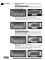
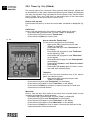
Functions of the controls on the push-button panel of the transmitting-console
The first 5 control levers
on the push-button
panel (beginning on the
right) have two plates
because they can control, through the selector (E/S - ) 5 functions
of the crane or the functions for stabilization.
Hereunder are reported
the plates which correspond to the stabilization functions.
LINEAR PUSH-BUTTON PANEL SCANRECO
fig. 10
DISPLAY
SELECTOR
E/S -
LEVERS CD
radio starting
and audible alarm
radio turning off
and stop button “STOP”
LEVERS CD
The three control joysticks on the push-button panel have two
plates because they
can control, through
the selector (E/S - )
the functions of the
crane or the functions
for
stabilization.
Hereunder are reported the plates which
correspond to the stabilization functions.
LEVER C
LEVER C
PUSH-BUTTON PANEL SCANRECO WITH JOY-STICK
fig. 10a
DISPLAY
SELECTOR
E/S -
LEVERS CD
radio turning off
and stop button “STOP”
LEVERS CD
LEVER C
radio starting
and audible alarm
LEVER C
13
13.2
Selector (E/S -
SUPPLEMENTARY
BEAMS
GR5
S3
) Selector for the use of the crane or the outriggers.
Levers CD
Controls to select the outrigger supports and rams.
Levers C
Control of the selected outrigger support or ram.
E1
E4
S2
E3
S1
S4
E2
F
R
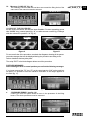
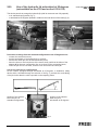
MANOEUVRES OF THE OUTRIGGER RAMS IN
CASE OF AN ELECTRICAL FAILURE
In case of an electrical failure, electrical or hydraulic malfunctions, you cannot use the selectors on
the push-button panel and so it is necessary to
operate directly the integrated group of the outrigger control (fig. 11) after removing the protection.
U
G
fig. 11
fig. 11b
Example: re-entry of the outrigger ram S1
- tighten the T screw (fig. 11a)
- remove the lead seal placed on the electrovalve G (general), push the button and
then turn it clockwise (fig. 11b pos. 1-2); the button stays in the closed position.
- Unscrew the knurled screw of the electrovalve S1 of the outrigger.
- Push with an appropriate metal tip and in the direction of the arrow F the slider
of the spool R (general) to re-enter the ram.
- Re-screw the knurled screw of the electrovalve S1 of the outrigger.
- Put the button of the electrovalve G back to its original position, by turning
it anti-clockwise (fig. 11b pos. 3-4)
- to reactivate the crane functions loosen the T screw, to the previous position (see fig. 11a)
T
fig. 11a
PICTURE LIST (fig. 11):
G electrovalve for main bypass
U electrovalve for the ram descent and extension of the
outrigger supports
R electrovalve for the ram re-entry and retraction of the outrigger supports
E1 E2 E3 E4 electrovalve of the extension rams
S1 S2 S3 S4 electrovalve of the outrigger rams
T electric deviator of the crane-outriggers (fig. 11a)
After such emergency operations and prior to re-use of the crane, you must
immediately go to a FASSI authorised Center for the repair of the fault and resealing of the device.
(!)
13.3
Interferences with the valves or removal of the lead seal release the
FASSI GRU IDRAULICHE
from any responsibility and invalidate the warranty.
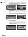
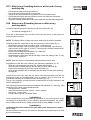
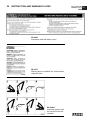
Controls to stabilize the vehicle
13.3.1 Crane with fixed or manually tiltable supports
for outrigger rams
A
fig. 12
- Disengage the locking devices of the outrigger supports by putting the levers A
from the position of the fig. 12 to the one of the fig. 12a.
- Position lever D of oil diverter (
fig. 12a
-E/S) on E/S.
fig. 12b
- Position selector ( -E/S) of the push-button panel on E/S.
(you read “outriggers” on the display)
- By using the levers CD and the lever C extend
the outrigger supports and lower the outrigger
rams till the complete stabilisation of the vehicle.
Example of using the levers CD and the lever C:
- extension of the outrigger support n°1
- activate the lever CD n°1 in the direction
of E.
- by keeping activated the lever CD n°1, activate the lever C in the opposite
direction.
- descent of the outrigger ram n°1
- activate the lever CD n°1 in the direction of S.
- by keeping activated the lever CD n°1, activate the lever C in the opposite
direction.
(!) ATTENTION (!)
The complete extension of the outrigger supports is visually indicated by the
yellow triangles which are found at the end of the beam (and of the support if
it’s supplied with extra double extension beams). (Fig. 12b).
The stabilization has to be carried out with care and gradually keeping the vehicle
in horizontal levelled condition to prevent springs overloads and chassis torsions.
(!) ATTENTION (!)
During the stabilising operations, for each outrigger ram, it is recommended to
DESCENT the outrigger as the last manoeuvre.
To operate the crane controls, after having completed the stabilisation manoeuvres,
- Position lever D of oil diverter (
- E/S) on
.
- Position selector ( -E/S) of the push-button panel on
.
Manoeuvres for re-entry of the crane outriggers and supplementary outriggers within the overall vehicle width after crane use.
-
Repeat by reversing the sequence of the operations effected for the stabilisation
of the vehicle.
(!) ATTENTION (!)
Keep hands clear of automatic stop device of the outrigger supports (Fig. 12).
(!)
Always check that the outrigger supports, once in their rest position, are
locked in their seat by the safety devices, so as to assure the impossibility
of accidental movement. (Fig. 12).
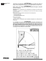
13.3.2 Crane with hydraulic tiltable supports (WITH CHAIN)
for outrigger rams:
(!) ATTENTION (!)
Be very careful during vehicle stabilization operation; make sure that there are no obstacles preventing the rotation of the rams and that no one is or transits in close proximity of the working area of the outriggers.
- Disengage the locking devices of the outrigger supports by putting the
levers A from the position of the fig. 12 to the one of the fig. 12a.
- Position lever D of oil diverter (
- Position selector (
-E/S) on E/S.
-E/S) of the push-button panel on E/S.
- By using the levers CD, the lever C and the valve taps, extend the outrigger
supports, rotate the outrigger rams putting in a working condition and lower
them till the complete stabilisation of the vehicle.
Example of using the levers CD, the lever C and the valve tap on the outrigger and the
valve tap on the control ram for the tiltable support:
- extension of the outrigger support n°1
- activate the lever CD n°1 in the direction of E;
- by keeping activated the lever CD n°1, activate the lever C in the opposite
direction.
SUPPLEMENTARY
BEAMS
GR5
13.3.1
13.3.2
SUPPLEMENTARY
BEAMS
GR5
R1
- rotation of the outrigger ram n°1 from the rest position (fig. 13) to the working
condition (fig. 15)
- make sure that the tap R1 of the valve of the outrigger ram S1 is closed
(for the closed or opened position see fig. 14);
- open the tap R2 of the valve of the control ram for the tiltable support;
- to remove the pin 2 proceed as follows:
- activate the lever CD n°1 in the direction of S;
- by keeping activated the lever CD n°1, activate the lever C in the opposite
direction to control the rotation and take the ram S1 to its rest position so that
the pin 2 is extractable;
- lift the parking pin 1 (safety) until it is released and remove from its seat the pin 2;
- to rotate the outrigger ram S1 proceed as follows:
- activate the lever CD n°1 in the direction of S;
- by keeping activated the lever CD n°1, activate the lever C in the opposite
direction till the requested extension of the outrigger ram S1.
1
!!! ATTENTION !!!
Make sure that no one is or transits in close proximity of the working area of
the outriggers.
2
-manually complete the rotation by positioning the ram vertically, insert the
pin 2 in its new seat and lock it with the parking pin 1 (safety);
-close the tap R2 of the valve of the control ram for the tiltable support
R2
(!)
fig. 13
The locking pin 2 is constructed from special material
- do not replace it with a non original part
- your security depends on it
- descent of the outrigger ram n°1
- open the tap R1 of the valve of the outrigger ram S1;
- activate the lever CD n°1 in the direction of S;
- by keeping activated the lever CD n°1 activate the lever C in the opposite
direction till the requested extension of the outrigger ram S1;
- close the tap R1 of the valve of the outrigger ram S1.
(!) ATTENTION (!)
The complete extension of the outrigger supports is visually indicated by the
yellow triangles which are found at the end of the beam (and of the support if
it’s supplied with extra double extension beams). (Fig. 12b).
fig. 14
The stabilization has to be carried out with care and gradually keeping the vehicle in
horizontal levelled condition to prevent springs overloads and chassis torsions.
(!) ATTENTION (!)
During the stabilising operations, for each outrigger ram, it is recommended to
DESCENT the outrigger as the last manoeuvre.
To operate the crane controls, after having completed the stabilisation manoeuvres,
- Position lever D of oil diverter ( -E/S) on
.
- Position selector ( -E/S) of the push-button panel on
.
Manoeuvres for re-entry of the crane outriggers and supplementary outriggers
within the overall vehicle width after crane use.
-
fig. 15
Repeat by inverting the sequence of the operations effected for the stabilization
of the vehicle.
(!) ATTENTION (!)
Keep hands clear of automatic stop device of the outrigger supports. (Fig. 12).
(!)
Always check that the outrigger supports, once in their rest position,
are locked in their seat by the safety devices, so as to assure the
impossibility of accidental movement. (Fig. 12).
14
CONTROLS TO OPERATE THE CRANE
14.1
Generality
CONTROLS TO
OPERATE THE CRANE
GR5
14
(!) WARNING (!)
Before operating the crane it is compulsory to set the
outriggers. (Plate DE2327 fig. 16)
Radio remote control
The crane and hydraulic implements can be operated through proportional radio remote control subjugate to a distributore which the
manual order is to be used only in case of emergency.
Display on the push-button panel of the radio remote control
fig. 16
- When you start the radio remote control (fig. 10), the pressure
in the inner, outer ram and the jib and the percentage of load
on the winch are displayed.
In relation to the view chosen like standard, when you start the radio remote control the
pressure values are displayed in:
- “bar” if on the display, on the left of the values, no symbol is present.
- “daPsi” if on the display, on the left of the values, the symbol is present.
*
-
-
By pushing the button
the percentage values of pressure in the inner, outer ram
and the jib and the percentage of load on the winch are displayed.
By pushing a second time the button
the pressure values in the inner, outer and jib
rams movement in the measurement unit non standard and the percentage of load on
the winch are displayed.
By pushing again the button
you return to the initial display.
For the use of the control button
see Par. 22.2.
By pushing the button
one or more times you return to the initial display
(view of the pressure values).
For the meaning of other messages see Par. 16.7.1 “Diagnostic”.
You can select whether to control the crane or the outrigger functions using the buttons
placed on the remote control as follows:
- To operate the crane, position the A-B selector (pos. 5) on A and the selector (E\S- )
(pos. 1) on ; then press together the left confirmation button (OK) (pos. 2) and the
right confirmation button (OK) (pos. 6 for joy-stick controls, pos. 7 for linear controls).
“Crane” appears on the display.
When turning on, the remote control asks for selector confirmation (E\S- ) on display;
to confirm press together the two left-right (OK) confirmation buttons (pos. 2 and pos. 6
for joy-stick controls, pos. 7 for linear controls).
Tele-radio remote control
The radio remote control, in the case of a discharged battery or in the presence of interference in the radio transmission, or use of the crane in situations where the transmission by radio
is forbidden, it is easily transformed to cable remote control using a connecting cable.
Activation of the tele-radio remote control
Connect by cable the remote control to the socket fixed on the base of the
crane (fig. 17)
(!) WARNING (!)
First read the instructions given in the User’s Manual supplied by the Manufacturer
before using the remote control to avoid improper use.
The plates shown on the side of each push-button panel lever of the radio remote control and on
each lever on the emergency control, determine the operation of the levers in relation to the
movement of the crane.
(!) ATTENTION (!)
The sequence of the plates placed on the crane controls may be different.
Make sure that the lever you are going to operate correspond to the control you selected.
(!) Operate the levers smoothly and gradually (!)
When carrying out simultaneous movements of two or more functions, also related to
pump flow and lever travel, it is possible that on reaching the stroke end of a particular
function, an increase in speed of the other functions will occur.
fig. 17
14.1
CONTROLS TO
OPERATE THE CRANE
Functions of the controls on the push-button panel of the transmitting-console
GR5
LINEAR PUSH-BUTTON PANEL SCANRECO
ACCESSORY CONTROLS
CRANE CONTROLS
DISPLAY
RED LED 100%
YELLOW LED 90%
socket for
serial cable
SELECTOR
E/S -
fig. 10
radio turning off
and stop button
“STOP”
selector for the use of the outriggers (E/S) or of the crane ( )
exclusion push-button for the lifting
moment limiting device
switching of the selector for the
use of the 9°/10° function
radio starting
and audible alarm
= control button
= GAS +
= control button
= GAS -
= free
selector for the use of the crane
standard or XP
control button =
selector for the use of the right control panel in configuration A or B
control button =
= starting
the engine
= turning off
the engine
Functions of the controls on the push-button panel of the transmitting-console
GR5
PUSH-BUTTON PANEL SCANRECO WITH JOY-STICK
DISPLAY
RED LED 90%
YELLOW LED 90%
socket for
serial cable
SELECTOR
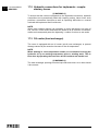
E/S -
fig. 10a
radio turning off
and stop button
“STOP”
selector for the use of the outriggers (E/S) or of the crane ( )
radio starting
and audible alarm
= control button
= GAS +
exclusion push-button for the
lifting moment limiting device
selector (enter) for control =
GAS - =
switching of the selector for
the use of the 9°/10° function
= free
selector for the use of the crane selector (various times) for control =
standard or XP
starting the engine =
selector for the use of the right
control panel in configuration A
or B
CONTROLS TO
OPERATE THE CRANE
= selector (index-return) for control
= turning off the engine
14.1
14.2
CONTROLS TO
OPERATE THE CRANE
14.2
GR5
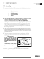
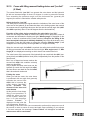
Manoeuvres to unfold the crane into a working
condition
The plate DE4452A indicates the sequence of the manoeuvres to be carried
out to unfold and to fold the crane.
- Engage the power take off.
- Stabilize the vehicle (see details on Paragraph 13 “Manoeuvres
and controls to stabilize the vehicle”).
By operating the corresponding levers:
- make sure that the extension booms and the outer ram are closed;
- lift the inner boom over the horizontal line;
- open the outer boom to the “horizontal” position;
- position the hook on the vertical line above the load.
14.3
Manoeuvres to fold the crane into the
rest condition (see plate DE4452A)
By operating the corresponding levers:
- fold the extension booms to their stroke end;
- lift the inner boom to its stroke end;
- fold the outer boom to its stroke end;
- rotate the crane until the arrows coincide (on the base and on the
slew ring);
- fold the inner boom to its stroke end; the rest locating pin locates
into its seat;
- re-position the outriggers to within the overall vehicle width as
described on Paragraph 13.
fig. 18
16
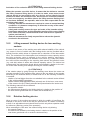
16.1
(!)
MANOEUVRES OF THE CRANE LOADS
Generality
Before manoeuvering the load, verify that the working area
is suitable for your crane.
The lifting curves of the capacity plate indicate the maximum load that the crane
can lift at a certain radius and at a certain height. To utilize the maximum capacity
of the crane, it is necessary to position the inner boom as indicated on the capacity plate; the coloured symbols on the inner boom and column must coincide.
During load handling, do not exceed the reach limits given, or the load indicated
on the above mentioned charts. If the limits are exceeded, the load limiting device, allowing all manoeuvres, which reduce the lifted load within the permitted
reach limits and forbid all other manoeuvres, will be immediately activated.
On the crane has been installed an electronic system to automatically control
the maximum speed for moving the booms in relation to the load applied. With
low loads, the control system allows the use of the nominal capacity of the
pump, while the oil capacity available for the moving, is automatically and progressively reduced, at the increased loads.
The manoeuvres affected by this system are:
- rotation
- lift and descent of the inner boom
- lift and descent of the outer boom
- exit of the extension booms of the crane
- lift and descent of the jib (when fitted)
- exit of the extension booms of the jib (when fitted)
Lifting moment limiting device
A characteristic which permits the classification of cranes is their lifting capacity or
maximum lifting moment. The moment is defined by the value obtained from the
weight of the load to be lifted (kg) by its distance (meters) from the centerline of the
crane rotation. The device called “lifting moment limiting device” preserves the
crane structure from overloads, as it prevents any movement which increases the
value of the moment up to the maximum established value.
16.2
“Electronic” lifting moment limiting device
This device utilises an electro-hydraulic system managed by an electronic logic
that prevents any operation tending to cause an increase in the pressure induced
by the load in the lifting rams (inner, outer rams of the crane and of the hydraulic
extension, if fitted), up to the critical values. These values, which are not exceedable, determine the intervention levels and provide the data for setting the device.
The pressure values detected in the lifting rams are turned into electric signals by
the transducers, and sent to the electronic logic of the device which determines
the locking or unlocking of the controls concerned, according to the horizontal
position of the crane outer boom (mercury level switch); only the controls allowing
a reduction of the overload are enabled, while those increasing it are disabled.
The device features an electro-hydraulic control that does not allow the set value
to be exceed, by deactivating the controls (levers in neutral position) commanded
by the limiting device. When the controls are released (levers in neutral position)
it's this electronic logic that handles which manoeuvres are disabled, according to
the position of the crane outer boom and in overload condition, by sending electric signals to special micro-switches placed on the elements of the distributor.
(!) ATTENTION (!)
The presence of the lifting moment limiting device does not release the
user from the obligation to respect what is indicated on capacity plates
and lifting curves.
CONTROLS TO
OPERATE THE CRANE
GR5
16
16.3
CONTROLS TO
OPERATE THE CRANE
16.3
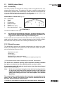
Control panel
GR5
The control devices are insered in the push-button panel of the radio remote
control.
For the picture list of the push-button panel of the radio see “Controls to operate the crane”.
If the warning light over the on radio button comes on, it confirms that the control unit has been activated.
!NOTE!
In the absence of electric power all crane functions will be
desactivated.
If during operation the yellow led placed on the side of the display comes on,
90% of the rated capacity has been reached.
If during operation the red led placed on the side of the display comes on, the
activation value of the lifting moment limiting device has been reached.
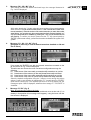
Visual indicator yellow/red light
The control unit was up to 90% loading a graduated band of led lights to show
the increased load, upon reach 90% a yellow led will be illuminated, upon reaching 100% and activation of the lifting moment limiting device a red led will be
illuminated. The visual indicator located on the crane is shown in fig. 19.
Any hidden danger situation for persons must be audibly warned by pressing
the push button of the audible alarm (on radio and audible alarm push button).
When there are serious, imminent and dangerous conditions for persons and
things during load handling, operate on the STOP button, which isolates all
crane functions and activate the intermittent audible alarm push button.
1
fig. 19
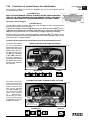
16.4 Load handling
CONTROLS TO
OPERATE THE CRANE
Manoeuvres of the crane
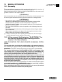
Fig. 20a-b e 20c-d illustrate the configurations of the crane (and of the eventual hydraulic
extension) with the manoeuvres allowed and not allowed
WITH HYDRAULIC JIB
by the device, in connection with the horizontal position
of the crane and extension outer booms.
GRU FASSI
16.4
(!) ATTENTION (!)
In the overload condition, if you simultaneously effect one
permitted and one non permitted manoeuvre you haven’t
movement. In the overload condition, before effecting a
permitted manoeuvre, it is necessary to return all the
levers to the neutral position.
(!) ATTENTION (!)
During load handling with the crane and with the crane
and hydraulic jib, in vertical configuration or close, the operator must strictly
refer to the loads indicated on the capacity plates since the limiting device
shows to be not particularly sensitive with vertical lifts.
fig. 20a
WITHOUT HYDRAULIC JIB
Crane with activated limiting device by the intervention of the crane or the
hydraulic jib (overload condition) and with outer boom of the crane above the
horizontal line fig. 20a-20b
Manoeuvres not allowed:
- Inner boom descent
- Outer boom descent
- Extension of the crane extension boom sections (*)
- Lift and descent of the hydraulic jib
- Extension of the extension booms section of the jib
- Winch rope lift
- Movement of the hydraulic accessories (**)
NOTES: (*) If the overload condition has been activated by the hydraulic extension, the
extension of the crane boom sections is permitted.
(**) It is permitted only when coupled with permitted manoeuvres.
Manoeuvres allowed: all the manoeuvres that bring the load closer to the column and
therefore the overload
- Rotation in both directions
- Inner boom lift
- Outer boom lift
- Re-entry of the crane extension boom sections
- Re-entry of the jib extension boom sections
- Winch rope descent
fig. 20b
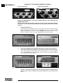
WITH HYDRAULIC JIB
Crane with activated limiting device by the intervention
of the crane or the hydraulic jib (overload condition)
and with outer boom of the crane under the horizontal
line fig. 20c-20d
Manoeuvres not allowed:
-- Inner boom lift
- Outer boom lift
- Extension of the crane extension boom sections (*)
fig. 20d
- Lift of the hydraulic jib
- Extension of the extension booms section of the jib
- Winch rope lift
- Movement of the hydraulic accessories (**)
NOTES: (*) If the overload condition has been activated by the hydraulic
extension, the extension of the crane boom sections is permitted.
(**) It is permitted only when coupled with permitted manoeuvres.
Manoeuvres allowed: all the manoeuvres that bring the load closer to the
column and therefore the overload
- Rotation in both directions
- Inner boom descent
- Outer boom descent
- Re-entry of the crane extension boom sections
WITHOUT HYDRAULIC JIB
fig. 20c
16.4
CONTROLS TO
OPERATE THE CRANE
GRU FASSI
- Descent of the hydraulic jib
- Re-entry of the extension booms section of the jib
- Winch rope descent
Crane with activated limiting device (overload condition) by the intervention
of the load limiter of the winch
Manoeuvres allowed:
- Rotation in both directions
- Re-entry of the crane extension boom sections
- Re-entry of the jib extension boom sections
- Winch rope descent
Manoeuvres not allowed:
- all other movements
Crane without load applied and activated limiting device
The limiting device may intervene also during loadless crane operation following a pressure peak provoked by the attainment of the stroke end of the lifting ram at high speed. In this
condition, reactivation of the crane commands by performing one of the manoeuvres is
allowed by the system. If the limiting device intervenes when both the lifting rams are open
and at stroke end, and the crane extension booms are fully folded, it is not possible to reactivate the commands, since the permitted manoeuvres (arm lifting and extension fully
retracted) cannot be carried out, because of the actual configuration of the crane (outer
boom above the horizontal). The device, in this case, allows the descent manoeuvres
since it verifies the it was a peak pressure inside the lifting rams; the crane being loadless,
thus these manoeuvres will be allowed.
Temporised exclusion device of the lifting moment limiting device
The activation of the exclusion device is permitted when the limiting device is activated
and only in the case when it is impossible to carry out any of the allowed manoeuvres.
This generally occurs when handling heavy and bulky loads, with the outer boom
above the horizontal and the extension boom sections almost retracted.
(!) ATTENTION (!)
The activation of the exclusion system for the lifting moment limiting device
can ONLY be operated when the extension booms of the crane and of the
hydraulic jib (when fitted) are fully retracted.
The activation button of the excluding device, only in the case of the crane, are
to be activated as follows:
- retracted the crane extension booms until stroke end and momentarily pressurise;
- maintain the command for the extensions boom until the red led of the button LMI
placed on the control panel begins to flash;
- continue to keep the command for the extensions boom and press the exclusion
device button, the flashing red light becomes fixed;
- release the lever commanding the extensions booms.
The permitted manoeuvre is the descent of the outer boom in order to bring it under
the horizontal; remember that you have at your disposal five (5) seconds from the
command operation to carry out the descent. After such period of time, wait at least
one (1) minute in order to be allowed to carry out the manoeuvre once again.
The activation button of the excluding device, only in the case of the hydraulic jib,
are to be activated as follows:
- retracted the extensions booms of the hydraulic jib until stroke end and momentarily
pressurise;
- maintain the command for the extensions of the hydraulic jib boom until the red
led of the button LMI placed on the control panel begins to flash;
- release the lever commanding the extensions booms of the hydraulic jib;
- within 3 seconds from releasing the lever commanding the extensions booms of
the jib, retracted the extensions booms of the hydraulic jib until stroke end and
momentarily pressurise (the red led turns off as soon as the re-entry begins);
- maintain the command for the extensions boom until the red led of the button
LMI placed on the control panel begins to flash;
- continous to keep the command for the crane extensions boom press the
exclusion device button, the flashing red light becomes fixed;
- release the lever commanding the crane extensions booms.
The permitted manoeuvre is the descent of the outer boom in order to bring it under
the horizontal; remember that you have at your disposal five (5) seconds from the
command operation to carry out the descent. After such period of time, wait at least
one (1) minute in order to be allowed to carry out the manoeuvre once again.
(!) ATTENTION (!)
Activation of the exclusion device of the lifting moment limiting device.
When the operator uses this device, it means that he wishes to override
the lifting moment lifting device in order to make some manoeuvres
(which would be impossible with the device active) that bring the
moment to within the maximum level, but involve an overload condition.
In such an emergency condition (where the lifting moment limiting device has been disabled), the operator, who is the main responsible for the
machine safety, must:
- carefully consider the manoeuvres required to return to normal working
conditions: it is however compulsory to effect the re-entry of the extension booms at first,
- calmly and carefully assess the type and scale of the hazards arising
from these manoeuvres and the possible reaction of the crane (tipping
over, frame overload, uncontrolled fall of the load due to a hydraulic
system overload etc.);
- make all movements as slowly as possible to reduce the dynamic
overload to the minimum.
16.5
Lifting moment limiting device for two working
sectors
In case of one sector of the working area with reduced stability of the vehicle
(e.g. sector in front of vehicle cab) the limiting device can be provided with a
special function which allows to operate with a reduction of the intervention
level. The reduction of the intervention level reduces the crane capacity values
and this reduction value is defined in the vehicle stability calculation.
Consequently the working area is divided in one sector (e.g. body side) where
the crane works according to the capacity plate values and another sector
(e.g. cab side) where it works with reduced capacity values. The device has
consequently two intervention levels which are activated in relation to the sector of the crane working area always securing the vehicle stability.
(!) ATTENTION (!)
If the rotation stops by going through the working zone where the crane can
operate according to the capacity plate values to the one where it can operate
according to the reduced values, it means that one of the following conditions
is reached:
- rotation of a load bigger than the one admitted in the reduced sector defined
in the vehicle stability calculation;
- rotation without load applied but with (at least) one of the inner, outer rams
of the crane or the jib (if fitted) extended and pressurised at the stroke end.
The following manoeuvres are allowed:
- the opposite rotation
- the manoeuvres allowed by the limiting device in relation to the position of
the outer boom (positioned over or under the horizontal line).
16.6
Rotation limiting device
When a sector of the working area exists in which the stability is insufficient (for
example in the area in front of the cab) the permitted arc of rotation is limited by
means of an adjustable electro-hydraulic device which only allows operation within
the safe area. (Warning: persist in the operation!)
When exceeding the “safe area” the rotation limiting device only allowing:
- the opposite rotation
- the manoeuvres allowed by the limiting device in relation to the position of the
outer boom (positioned over or under the horizontal line).
CONTROLS TO
OPERATE THE CRANE
GRU FASSI
16.5
16.7
CONTROLS TO
OPERATE THE CRANE
GRU FASSI
If a reduction of capacity is necessary because of insufficient stability of the
complete unit, new capacity plates must be fixed giving the derated capacity in
accordance with the final stability test.
(!) ATTENTION (!)
Always check carefully that the vehicle is perfectly stable, paying special attention to the area immediately in front of the driver’s cabin as this is usually less
stable.
16.7
In the case of the appearance of the signal “ALARM”
on the display of the control panel or of the radioremote
control or in case of an electrical failure.
In these cases, because of a fault, shown in the system, the crane is not functional any more. The checks that the operator can effect to reactivate the crane
functions are the following:
- in case of an electrical failure check the connection of the feeding cables to
the battery;
- in case of the appearance of the signal “ALARM” on the display of the pushbutton panel see Par. 15.7.1 and check if the fault can be resolved by the
operator.
If the fault cannot be resolved, you must immediately go to a FASSI authorised Center after bringing the crane to its the rest position in relation to the
conditions explained in the paragraphes 15.7.2, 15.7.3.
16.7.1
Diagnostic (Alarms/Input/Output) LME vers. 4-5 UC 01-7
It is possible to install on the machine some operation improvements of the
limiting device not yet described here. For this purpose compare the released
version of the software installed on the machine (you can read it on the display
when switching on) with the one in this paragraph's heading. For further explanations please refer to Fassi service network.
All the eventual problems that the electronic device can have are shown on the
display of the control panel and they create the stop of all crane functions. The
visualisation of the alrm must be reset pushing the button l.m.l.d. exclusion on
the main box control panel, which bring again the display in the original screen
showing the pressures only if the problem has been solved. As consequence
of this, when appear an alarm signal it is necessary to solve the problem
because only in this case will be possible to reset the display and reactivate
the crane working.
ALARM
01
02
04
06
08
09
10
11
12
14
15
16
17
18
19
20
21
22
CODES:
CONTROLS TO
OPERATE THE CRANE
- electronic card alarm
- inner ram transducer alarm
- outer ram transducer alarm
- jib articulating ram transducer alarm
- proximity sensor alarm (central one off)
- proximity (lateral one off)
- mercury sensor level alarm (connector disconnected)
- mercury sensor level alarm (sensor defect)
- winch alarm
- microswitch on the inner ram distributor segment alarm
- microswitch on the outer ram distributor segment alarm
- microswitch on the jib articulating ram distributor segment alarm
- microswitch on the extension rams distributor segment alarm
- microswitch on the jib extension rams distributor segment alarm
- microswitch on the winch distributor segment alarm
- microswitch on the rotation distributor segment alarm
- 10A fuse alarm (fuse inside the main control panel protecting
the emergency circuit)
- winch stroke end device alarm
Only for crane with slew ring:
30
31
32
33
34
35
36
40
41
42
- inconsistency of the rotation lever movement alarm
- inconsistency of the inner ram lever movement alarm
- inconsistency of the outer ram lever movement alarm
- inconsistency of the crane extension ram lever movement alarm
- inconsistency of the jib articulating ram lever movement alarm
- inconsistency of the jib extension ram lever movement alarm
- inconsistency of the winch lever movement alarm
- CAN-BUS reading alarm on unit FX003
- CAN-BUS reading alarm on unit FX004
- CAN-BUS reading alarm on radio remote receiver unit
MESSAGES
"WINCH OFF"
EXPLANATION
- information for the activation of the winch up or down.
"WINCH CAL.ERROR" - flashing warning (10 seconds each minute); it appears
when the maximum detection of the winch adjustment
with load is exceeded.
"STOP BOOM OUT"
- warning for the interruption of the extension boom exit
because of a sudden variation of the cable tension.
"STOP JIB 25°"
- warning of not permitted activation of the lifting functions
because of the activation of the maximum vertical operativity of the jib when it is complete with the 25° angle
increasing.
"PLE"
- activation of the speed reduction for the use of the
access platform.
GRU FASSI
16.7.1
16.7.1
CONTROLS TO
OPERATE THE CRANE
What to do in case of alarm
GRU FASSI
CODE
01
02
04
06
08
09
10
11
12
14
15
16
17
18
19
20
21
22
REMEDY
Take off the tension to the system and take on again the tension. If the
problem remains, take off the tension to the system again, take on the
tension and wait 12 minutes (12 minutes waiting time is a compulsory
condition and needs to be checked with a watch), take off the tension to
the system again, take on again the tension.
If the problem remains, you must immediately go to a FASSI
authorised Center.
Check the connector of the pressure transducer.
If the problem remains, you must immediately go to a FASSI
authorised Center.
See code 02.
See code 02.
Check if the red light on the proximity sensor is off and verify if
the metallic band is rightly positioned.
See code 08.
Check that the connector of the mercury sensor level is not damage.
If the problem remains, you must immediately go to a FASSI
authorised Center.
You must immediately go to a FASSI authorised Center.
See code 11.
See code 11.
See code 11.
See code 11.
See code 11.
See code 11.
See code 11.
See code 11.
Replace the 10A fuse at the nearest workshop after removing
the carter and the cover of the main panel FX000. (See electric
schematic Par. 5)
See code 11.
Only for crane with slew ring:
30
31
32
33
34
35
36
40
41
42
See code 11.
See code 11.
See code 11.
See code 11.
See code 11.
See code 11.
See code 11.
See code 11.
See code 11.
See code 11.
MESSAGES
"WINCH OFF"
REMEDY
Place the distributor bank lever controlling the winch in
neutral position.
"WINCH CAL.ERROR" See code 11.
"STOP BOOM OUT"
Place the distributor bank lever controlling the extension
booms in neutral position. If the warning appears when
the winch cable lifting stroke end is not reached, place in
any case the lever in neutral position and then restart to
operate.
"STOP BOOM UP"
Lifting functions not available; are authorized only descent
functions.
To verify the right working of the differents input it is possible to use the display
in the "INPUT" menu.
16.7.2
Temporary OVERIDE-REACTIVATION for the crane
functions in case of the appearance of the signal
“ALARM” on the display of the push-button panel
CONTROLS TO
OPERATE THE CRANE
GR5
16.7.2
Note: If the alarm doesn’t involve components which control the distributor, it is possible
to re-close the crane using the push-button panel of the radio remote control.
(!) ATTENTION (!)
These manoeuvres can be effected where the lifting moment limiting device has
been disabled, and then can involve an overload condition. In such an emergency condition, the operator, who is responsible for the machine safety, must:
- carefully consider the manoeuvres required to return to normal working conditions: it is however compulsory to effect the re-entry of the extension booms at
first,
- calmly and carefully assess the type and scale of the hazards arising from
these manoeuvres and the possible reaction of the crane (tipping over, frame
overload, uncontrolled fall of the load due to a hydraulic system overload etc.);
- make all movements as slowly as possible to reduce the dynamic overload
to the minimum.
Reactivation of the crane functions using the push-button panel of the radio:
Keeping pressed the exclusion push-button ( ) of the limiting device on the pushbutton panel, operate on the lever of the movement to be effected.
After such emergency operations and prior to re-use of the crane, you must
immediately go to a FASSI authorised Center for reactivation of the crane
functions and re-sealing of the device.
(!)
Interferences with the valves or removal of the lead seal release the
FASSI GRU IDRAULICHE
from any responsibility and invalidate the warranty.
16.7.3
Temporary OVERIDE-REACTIVATION for the crane
functions in case of an electrical failure, out of order of
the radio remote control, or of the appearance of
the signal “ALARM” on the display of the push-button
panel (in this case, we cannot reactivate the crane
functions).
On the distributor it has been installed an emergency lever to be used in the
event of a black-out, electrical or hydraulic malfunctions. Only In these situations
it is permitted to remove the lead seal placed on the tap lever and place it in the
closed position.
For the access to the tap lever remove the cover 1 (fig. 21) placed under the protection guard of the distributor by unscrewing the two fixing screws (10 mm hexagonal spanner).
(!)
When the electric power is restablished, remember to put the lever in
the opened position.
(!) ATTENTION (!)
Activation of the emergency lever.
This activation prevents the operation of the lifting moment limiting device,
consequently, the operation under such conditions can involve an overload
condition. In such an emergency condition (where the lifting moment limiting device has been disabled), the operator, who is responsible for the
machine safety, must:
- carefully consider the manoeuvres required to return to normal working
conditions: it is however compulsory to effect the re-entry of the extension
booms at first,
1
fig. 21
16.7.3
CONTROLS TO
OPERATE THE CRANE
GR5
- calmly and carefully assess the type and scale of the hazards arising from
these manoeuvres and the possible reaction of the crane (tipping over, frame
overload, uncontrolled fall of the load due to a hydraulic system overload etc.);
- make all movements as slowly as possible to reduce the dynamic overload
to the minimum.
After such emergency operations and prior to re-use of the crane, you must
immediately go to a FASSI authorised Center for testing the structure and
re-sealing of the device.
(!)
Interferences with the valves or removal of the lead seal release the
FASSI GRU IDRAULICHE
from any responsibility and invalidate the warranty.
In case of an electrical failure, all the control levers of the push-button
panel of the radio-remote and the emergency control cannot be used
and then, it is necessary operate directly the distributor (fig. 22).
For the access to the distributor remove the cover 2 (fig. 22) by
unscrewing the five fixing screws.
The column controls must only be used in an emergency and only
to bring the crane to its rest position.
Be very careful at the manoeuvre of rotation because of the
residual danger of crushing.
During emergency manoeuvres, the operator, when it is possible
should be assisted by a second trained person who can intervene if necessary (Eg.: positioning the lever D of the deviator ( E/S) on E/S, by using then the deviator crane-outriggers like
interruption control of emergency.
2
(!) ATTENTION (!)
The presence of the lifting moment limiting device does not release the user from the obligation to respect what is indicated on
capacity plates and lifting curves.
fig. 22
(!) CAUTION DANGER (!)
On the outer boom there is a mercury capsule (mercury level switch) duly protected
and provided with the following warning stickers.
DE1680
Mercury is extremely toxic. In case of replacement and/or scrapping, dispose of or recycle the capsule containing mercury with maximum care, and in
accordance with the national regulations in force.
(!) ATTENTION (!)
Do not walk on... DE1679
Do not use water to estinguish fire! DE1680
DE1679
16.8
XP DEVICE
CONTROLS TO
OPERATE THE CRANE
This device can be activated only through the push-butoon panel of the radio
remote control, see Par. H0 “Controls to operate the crane”.
GR5_XP
16.8
The XP device works on the principle of an increase in the lifting capacity of
the crane with a reduction in the dynamic effect achieved with a reduction in
the speed of certain movements.
The XP device can be used, not just to increase the capacity crane:
- but to exploit the reduction in the speed when moving a load that must be positioned with precision.
- and to exploit the variation in the lifting moment limiting device adjustment
parameters to exit from a critical situation when moving the load (overcoming
of the 90% or intervention of the lifting moment limiting device).
(!) ATTENTION (!)
The rating plates relevant to the XP device are marked F....XP.
16.8.1
Activation and instructions for use of the XP/V device
You operate the XP device only from the console of the radio remote control by
using the appropriate selector (fig. 22a).
SCANRECO RADIO REMOTE CONTROL
RScanreco radio remote control
You operate on the XP/ON-XP/OFF selector (fig. 22a) on the XP/ON
position.
The activation of the XP device is indicated with the mark XP displayed
up on the right of the control panel.
(!) WARNING (!)
XP
It is recommended to release the crane controls (levers of the control
console in neutral position) before activating or desactivating the XP
device because of the variation of speed is considerable and immediate; carefully
operate the controls.
See paragraph 14 of the USE AND MAINTENANCE MANUAL for details of
“Controls to operate the crane”
See paragraphes 16 of the USE AND MAINTENANCE MANUAL for details of
“Lifting moment limiting device”
The activation of the XP device on cranes with free rotation or with rotation
limiting device produces:
- an increase in the capacity of the crane
- a reduction in the speed of rotation without increasing the torque
- a reduction in the speed of lifting and lowing the inner boom, outer
boom and of the jib boom (when fitted)
- speed of the extension booms, bucket and the rotator.
- allows normal speed and lifting capacity of the winch.
fig. 22a
16.9
CONTROLS TO
OPERATE THE CRANE
GR5_XP
The activation of the XP device on cranes with lifting moment limiting
device for two sectors produces:
- in the “stable” zone working area, the same effect for crane with free rotation
- in the “unstable” zone working area, a reduction in the speed without the
increase in capacity.
Activation of the XP device when the 90% of the capacity has been reached
- the yellow light on the "led" band of the push-button panel goes off
- allowing the manoeuvres that increase the lifting moment, you then have
the repeat of the yellow "led" band and red "led" band of the warning lights
again.
Activation of the XP device after the lifting moment limiting device block
A) The block continues:
- the crane must be reset
B) The red "led" band of the warning light switches off and the yellow "led"
band of the warning light usually comes on.
- the crane controls are enabled. Acting with the manoeuvres that increase
the lifting moment, you get the yellow and red warning lights again.
16.9
IMC AND ADC DEVICES
The IMC (Integrated Machine Control) device is an electronic brain that processes real-time information coming from the peripheral sensors and from the
crane electro-hydraulic systems; therefore it allows control of all functions and
movements with precision, fluidity and safety.
The ADC (Automatic Dynamic Control) device controls the dynamics of the
movements providing the maximum speed available subject to the applied
load.
17
USE OF IMPLEMENTS
USE OF IMPLEMENTS
GRU FASSI
17.1 Generality
The crane, in load condition H1B3, can be provided with implements such as:
-
Manual extensions
Winches
Hydraulic extensions
Personnel baskets
Clam ‘shell buckets
Augers
(!) When using an implement it is always necessary to check that its weight,
dimension and capacity is matched to the crane performances.
For further information please refer to FASSI GRU IDRAULICHE
Warning and norms for crane use also apply for hydraulic implement use.
Before using a personnel basket it is necessary to provide the crane with the
safety devices requested by the local norms in force, EN280 in Europe, and
prior to use of the crane it has to be tested and inspected in accordance with
the local legal requirements.
(!) When the crane is fitted with implements or laid on the truck body it is necessary
to check they are locked to assure the impossibility of accidental movements and
that the led signalling maximum obstruction in height (if fitted) confirms the correct
positioning of the crane.
(!) The crane can operate, intermittently and not continuously, with lifting
devices other than the hook, only on loose and light materials (not on
scrap iron).
(!) ATTENTION (!)
In case of using the crane with
lifting devices other than the
hook, the access to the working
area at the persons must be prevented.
The dimensions and the capacity
of the implements must be proportioned with crane performances.
(!) WARNING (!)
CRUSHING (F) OR PUSH (F) MANOEUVRES ARE NOT PERMITTED.
17
17.2
USE OF IMPLEMENTS
GRU FASSI
17.2 Hydraulic connections for implements - supplementary hoses.
(!) WARNING (!)
To ensure that the control corresponds to the implement movement, hydraulic
connections are symmetrically fitted with coupling unions. Never invert such
positions: movements inversion as well as operating difficulties or unusual
overload with implement itself could occur.
NOTE
When using coupling unions it is necessary to verify that there is no trace of
soil, curt etc. on the unions and inside the seats so as to avoid the oil contamination and consequently wear the tightening “ surface of unions or ram seals.
17.3 Oil cooler (heat exchanger)
The crane is equipped with an oil cooler (air-oil heat exchanger) to prevent
damage caused by an excessive increase of the oil temperature.
NOTE
When working in a low temperature climate, we recommend to bring the
hydraulic oil up to working temperature prior to starting work, This is
best done by operating the crane thru all its functions ram stroke end.
(!) WARNING (!)
The heat exchanger openings must be kept clear and clean. At no time should
it be covered.
18
MANUAL EXTENSIONS
18.1 Generality
These are additional extensions, which are placed in the hydraulic extensions of
the crane and of the hydraulic jib and secured by locking pins.
Manual extensions have a maximum capacity independent from the crane configuration as shown on the capacity plates.
(!) ATTENTION (!)
Manual extensions can be extracted from the rest position and be operative, once
the security pins have been removed, with the outer boom in sliding position.
(!) ATTENTION (!)
- Do not stand in front of stabilisers during operation!
Operate from a lateral position in respect of the extension movement of the
manual extensions; operation from the frontal position is dangerous.
- Verify that the area is suitable for this operation and there are no unauthorized
persons in the working area.
- Do not permit the extension to slide out at speed as this will damage the stroke
end stops.
- Do not try to align the holes (slots) for the locking pins with your fingers; always
use a suitable tool.
- When manual extensions are in place, fit the locking pins and secure them
with the check pins to prevent accidental escape.
(!) Always remember that when operating with implements, their tare weight
must be deducted from the capacity of the crane.
18.2 Lifting moment limiting device “ELECTRONIC” for
the manual extensions (valid starting from the
version 3.0 of the software)
HOW TO CONTROL THE LOAD HOOKED ON MANUAL EXTENSIONS.
This procedure aims to calculate the weight applied on the manual extensions.
It is necessary to apply the same procedure EVERY TIME you use the manual
extensions.
For its correct execution, follow meticulously the instructions reported HERE.
The extension limiting device IS NOT ALWAYS ACTIVE; on the contrary of the
crane limiting device, it responds about lifting a load only if QUESTIONED, therefore only if you enable the procedure. Remember that the procedure is
manual. In any case always refer to the capacity plates of the crane.
The limiting device for manual extensions, when interrogated, compares the real
weight applied on the lifting hook (inclusive of all the accessories attached) with
the value reported on the capacity plates. Such evaluation is effective only
during the execution of the procedure, therefore it is prohibited to add weight or
replace loads after the procedure is completed; in such case the procedure shall
be executed again from the start.
In the case one or more manual extensions are added or removed with respect
to the initial installation, it is COMPULSORY to have the crane initial configuration file modified accordingly (See Authorised Shops).
Before activating the procedure, extend and lock by a pin not only the manual
extension you intend to use but also the preceding ones.
USE OF IMPLEMENTS
GR2_45»60_3_4_5
18
18.2
PANELS OF THE RADIO-REMOTE CONTROL
USE OF IMPLEMENTS
GR2_45»60_3_4_5
Figure A (left side)
selector on A
Figure B (right side)
“+”
“ENTER”
“INDEX”
HOW TO PREDISPOSE THE USE OF MECHANICAL EXTENSIONS ON
CRANE OR ON JIB
Note: In case of crane with slew ring and top seat, all the procedures mentioned below can be executed from both the control panel and the radio-remote
control.
1.
fig. 1
fig. 1
2.
fig. 2
Initial display (Fig. 1)
Starting from the standard menu of the electronic lifting moment limiting
device displaying the pressures of the lifting rams (fig. 1), keep the “F1”
key (control panel), or the “+” and “ENTER” key (radio-remote control
with the selector on “A”, fig. A and B) pressed for some seconds.
Choice the installation of the manual extensions on Crane or on Jib.(Fig. 2)
If the crane features the installation of the manual extensions both on the crane
and on the jib, after the initial display, when you keep the “F1” (control panel)
or “+” and “ENTER” key pressed (radio-remote control), the program displays
the message illustrated in Figure 2.
fig. 2
Use the "+" button to select JIB if in the actual configuration the manual extensions
are mounted on JIB or CRANE if the manual extensions are mounted on the
crane.
3.
fig. 3
Message “M1 - M2 - M3” (fig. 3)
After having pressed the above mentioned keys, the message illustrated in
Fig. 3 will be displayed.
fig. 3
At this point, through the "+" button, select the correct number of the manual extension
at the moment in use (M stands for manual and 1, 2 and 3 indicate the number of the
manual extensions). Select the number of the manual extension you want; that number
starts blinking. You can select only the manual extensions that have been installed: i.e. if
only one manual extension is installed, by pressing the "+"key, only the M1extension will
start flashing. To confirm your choice, press once the “F1” key (control panel) or
“ENTER” (radio-remote control); you'll access the section dedicated to the system configuration
4.
fig. 4
Message “K1 - K2 - K3 - K4” (fig. 4)
[paragraph to read only in case of manual extensions installed on Jib and
not on Crane]
fig. 4
If you press the "ENTER" key with the manual extensions mounted on the
jib, the screen of Fig. 4 will be displayed.
Therefore we can choose the most convenient configuration among the
following:
K1 Outer booms of the crane totally re-entered and jib extensions as you like
K2 Outer booms of the crane as you like and jib extensions totally re-entered
K3 Outer booms of the crane totally extended and jib extensions as you like
K4 Outer booms of the crane as you like and jib extensions totally extended
Select the desired configuration using the * button to move among the various
options. Confirm your selection by pressing the “F1” (control panel) or “ENTER”
(radio-remote control) key. If the hydraulic jib boom is not at its stroke end, the
message at point 3 will be displayed; otherwise the message "F1 TO START" is
visualised.
5.
fig. 5
Message “FC P2” (fig. 5)
Note: do not hang any load on the hook.
This means that the outer ram must be positioned at its stroke end (if it is
already in that position this message won't appear), using the lever until the
next screen is displayed.
fig. 5
USE OF IMPLEMENTS
GR2_45»60_3_4_5
18.2
18.2
6.
USE OF IMPLEMENTS
GR2_45»60_3_4_5
fig. 6
fig. 6
7.
Message “F1 TO START” or “F1 / ENTER START” (Fig. 7)
At this point the display will visualize the message "F1 TO START" (control panel) or
"F1/ENTER START" (radio-remote control). Press the "F1" (control panel) key or
"ENTER" (radio-remote control) to continue.
fig. 7
fig. 7
8.
Message “UP P1” (see fig. 8)
Note: do not hang any load on the hook.
It requires the activation of the inner boom lifting to eliminate an overpressure at
the lifting ram bottom (the manoeuvre is activated but the crane does not move
since all the movements are disabled).
Note: set the lever of the inner ram at its stroke end to simulate the lifting
and keep it like this for at least three seconds.
fig. 8
fig. 8
9.
fig. 9
Message “FC P3” (fig. 6)
[paragraph to read only in case of manual extensions installed on Jib and
not on Crane]
Note: do not hang any load on the hook.
This means that the jib outrigger must be positioned at its stroke end (if it is
already in that position this message won't appear), using the lever until the
next screen is displayed.
Message “START LOAD P1” (vedere Fig. 9)
Releasing the lever in neutral position the display visualises the message
START LOAD P1.
It requires the slow lifting of the load using the inner ram. This allows to
haul it up from the ground in order to calculate the weight which will be
pointed out releasing the lever in neutral position.
fig. 9
10.
Message “LOAD OK” (fig. 10)
This message confirms that the load does not exceed the lifting limits of the
crane and of the manual extension selected.
USE OF IMPLEMENTS
GR2_45»60_3_4_5
fig. 10
fig. 10
CLOSING OF THE PROCEDURE
All the crane functions will still be kept disabled. To start operating press
the “INDEX” key (control panel fig. 10, or radio-remote control fig. D always
with the selector in position “A” fig. C).
“INDEX”
selettore su A
Figure C
Figure D
For an overall view of the procedure, we attach the diagrams showing all the passages and messages that can be displayed during the procedure according to the
various situations that may take place.
The script "EXIT" in the block diagram allows to exit the procedure.
FURTHER MESSAGES
After releasing the lever in neutral position you can find the following messages
If you keep pressed the "F2" key “F2” on the control panel or “LMI” on the push-button panel, it is possible to have an indicative evaluation of the weight applied on
the hook (fig. 11).
fig. 11
a.
fig. 12
fig. 11
“PRESSURE ERROR” (see fig. 12)
It warns you that the system found an error in the pressures of the lifting
booms. The whole procedure must be restarted.
fig. 12
18.2
18.2
b.
USE OF IMPLEMENTS
GR2_45»60_3_4_5
fig. 13
fig. 13
c.
“NO SPEED” (fig. 14)
The load has been lifted too quickly; the whole procedure must be repeated
from the beginning. The "LMI" key on the push-button panel or "F2" key on the
control panel is disabled because it has not been possible to calculate the
applied weight. Press INDEX on the push-button panel or "F1" key on the control panel to exit the procedure and go back to the standard operation. Put
down the load on the ground and repeat the whole procedure from the beginning.
fig. 13
fig. 13
d.
fig. 13
“NO LOAD” (fig. 13)
In this case the load exceeds the max lifting value of the selected manual
extension (it could still be on the ground). Unhook the load since it cannot
be lifted using the selected manual extension. As in the preceding case, if
you keep pressed the "F2" key, it is possible to have an indicative evaluation of the weight applied on the hook (fig. 11).
“NO LOAD CRANE!” (Fig. 15)
This message informs that the lifted load exceeds the max limit value of the
crane/jib, irrespective of the manual extensions, so that the load cannot be lifted
in this configuration due to the crane/jib overload. Also in this case the load must
be either removed or approached to the crane, and handled in a different way
without using the selected manual extension. Moreover the whole procedure
must be repeated from the beginning.
fig. 13
USE OF IMPLEMENTS
GR2_45»60_3_4_5
Electric schematic - crane with manual extensions
18.2
18.2
USE OF IMPLEMENTS
GR2_45»60_3_4_5
Electric schematic - crane with jib and manual extensions on jib
20 HYDRAULIC JIBS
20.1 Generality
USE OF IMPLEMENTS
GR3_4_5
The hydraulic jibs, foldable behind the cab, are additional booms, with articulation
and with one or more extension booms to be fitted to the last extension boom of
the crane; on request the manual extensions can be installed on the extension
booms of the jib.
NOTE
The weights reported in the table are indicative and can vary in relation to the fittings.
The jibs are fitted by means of the insertion of the extension connecting boom
into the crane extension boom; the fixing to the crane is obtained through locking
pins. The hydraulic connection to the supplementary functions of the crane, is
through quick couplings.
(!) Warnings and norms for crane utilisation apply also for hydraulic jibs use.
(!) ATTENTION (!)
The loads shown on the capacity plates which concern the configuration
of the crane with hydraulic jib, refer to the hydraulic jib and consequently
they are the same whether the crane has its extension booms retracted
or extended.
(!) Warnings and norms for manual extensions are indicated at Paragraph 18.
(!) ATTENTION (!)
It is recommended to employ lifting means adequate to the weight of the load
and radius of the extensions; during this operation the operator is responsible
for the machine safety. The slings or the cables used for handling the load
should have the adequate capacity and length; try to avoid the load overturning by having one length passed through itself and the other one through the
hook.
20.2 Identification of the hydraulic jib
The model, the version of the crane, the year of construction and the serial
number are stamped on the hydraulic jib (fig. 28) in the following sequence:
L102*03*001
A
B
C
A = model
B = year of construction
C = serial number
20.3 Nomenclature of the hydraulic jib
Pos.
Description
1. Connecting boom
2. Locking pins
3. Jib outer ram
4. Jib outer boom
5. Boom extension rams
6. Extension booms
7. Manual extension (on request)
8. Lifting hook
Punching
fig. 28
20
20
USE OF IMPLEMENTS
GR3_4_5
20.4 Manoeuvres to unfold the jib in working condition
- Operate as described to put the crane in working condition (paragraph 14.2).
By operating the corresponding levers:
- open the outer boom of the jib;
- extend the jib outer boom sliding sections;
- position the hook on the centerline of the load.
20.5 Manoeuvres to fold the jib in rest condition
By operating the corresponding levers:
- re-enter the hydraulic sections of the jib and of the crane;
- lift the inner boom to its stroke end;
- re-enter the outer boom of the jib and of the crane to its stroke end;
- operate, as described, to fold the crane in rest position.
(!) WARNING (!)
Always check and record the overall height of the crane in the folded
position or in laid position in the body or on the load.
Always respect and pay proper attention that the load and dimension
limits are in conformity with the road regulations.
20.6 Operations to remove the hydraulic jib from the crane
By operating the corresponding levers:
- re-enter the jib outer booms sliding sections to their stroke end;
- extend the crane outer ram to its stroke end;
- extend (of at least 1 - 1,5 m) the crane outer booms sliding sections;
- re-enter the outer ram of the jib and the inner ram of the crane to obtain
the two rest brackets of the jib, either lay on the ground, or on the truck
body or, if possible, on a specific rest trestle;
- remove screwing the locking pins;
- re-enter the outer booms sliding sections of the crane to free the first
boom of the crane jib;
- disconnect the jib from the hydraulic circuit of the crane operating on the
quick couplings.
(!)
Assure that the hydraulic jib is adequately stripped to avoid side turnover.
20.7 Operations to mount the hydraulic jib on the crane
By operating the corresponding levers:
- place the extension on the vehicle or on the ground in the direction of the
movement of the extension booms;
- extend the crane outer ram to its stroke end and position the extension
booms of the crane not too close to the first boom of the jib in order to allow
the lining-up manoeuvres and the connection of the hoses;
- connect the jib hoses to the hydraulic plant through coupling unions, following
indications of Paragraph 17.2, Hydraulic connections for implements - supplementary hoses;
- operate the outer ram of the jib and the inner ram of the crane in order to align
the extension booms of the crane and the first boom of the jib thus allowing their
connection;
- eventually repeat the previous operation until the fixing holes are aligned,
working on the extension booms of the crane;
- insert the lock pin into the fixing holes and secure it with the check pin.
20.8 Hydraulic jib articulated at 25 degrees with the
automatic control (L515-L516)
This device permits to arrange the hydraulic jib
articulated at 25 degrees upwards in relation
to the outer boom of the crane with the automatic control of the verticalising maximum
limit.
(!) ATTENTION (!)
If during the utilization, the verticalising limit value of the hydraulic jib (80 degrees
over the horizontal line) has been reached, the safety device intervenes preventing
every further verticalising:
Manoeuvres not allowed with the intervention of the safety device:
- lift of the inner boom;
- lift of the outer boom;
- lift of the jib mouvement boom.
Manoeuvres allowed:
- all other movements.
Device control
The device is continously monitored, therefore an eventual fault causes an
alarm signal on the control panels, and stop the three prevented movements
(see above) leaving all other movements free.
At this point it is necessary to read the alarm message and the paragraph which
concerns the alarms in the use and maintenance manual and follow the written
instructions.
USE OF IMPLEMENTS
GR5
20.8
20.9
Use of the hydraulic jib articulated at 25 degrees
(not available on the L102 and on the L515-L516)
USE OF IMPLEMENTS
GR4_5
This device permits to arrange the hydraulic jib (with its movement ram fully opened):
- or in standard configuration (fig. 1);
- or articulated at 25 degrees upwards in relation to the outer boom of the crane (fig. 2).
A
P
P
fig. 1
fig. 2
Procedure to change from the standard configuration to the 25 degrees’s one:
- re-enter the extension booms;
- put the hook attack of the hydraulic jib on ground;
- remove the check pin, the nut and extract the pin P;
- lower the inner or the outer boom of the crane slowly until that the holes of the
adapter A for the new configuration line up to those of the connecting boom;
- insert the pin P in its new seat, screw the nut and mount the check pin.
Use for the selector for configuration
On the cranes, equipped with jib articulated at 25 degrees, is installed a safety
device which, activated through the selector of the fig. 3, prevents the verticalising
of the jib further than the value reported on the capacity plates.
position of the selector
when the jib is in
standard configuration
position of the selector
when the jib is
articulated at 25 degrees
0
1
fig. 3
20.9
20.9
USE OF IMPLEMENTS
GR4_5
(!) ATTENTION (!)
This device is not automatic and so, it is compulsory to position the selector of
the fig. 3 on the configuration (standard or at 25 degrees) which you want to use.
(!) ATTENTION (!)
Before using, in the configuration of the jib articulated at 25 degrees, verify that
the device is efficient.
When the selector is positioned for the configuration at 25 degrees, the safety device
is activated.
If during the utilization, the verticalising limit value has been reached, the safety
device intervenes.
Manoeuvres not allowed with the intervention of the safety device:
- lift of the inner boom;
- lift of the outer boom;
- lift of the jib mouvement boom.
Manoeuvres allowed:
- all other movements.
When the selector is positioned for jib in standard configuration, the safety device is
disactivated.
(!) ATTENTION (!)
It is forbidden to use the crane with hydraulic extension articulated at 25
degrees without enabling the corresponding safety device (fig. 3) since when
the vertical disposition angles of the jib extension are higher than those of
the standard configuration, the extension boom sections of the crane and of
the hydraulic jib can generate a very dangerous situation because they are
not designed to work with the reverse actions.
20.10 Crane with lifting moment limiting device and "pro link"
(if fitted)
The cranes fitted with “pro link” can operate the outer boom and the hydraulic
jib with an increased angle of about 15 degrees. In order to prevent the booms
from exceeding the maximum angle over the horizontal line (generally 80
degrees) the crane is fitted with a suitable safety device.
Safety device for “pro link”
The safety device receives the signals about the inclination of the outer boom of the
crane and of the hydraulic jib and transmits them to the limiting system that controls
the manoeuvres; the significant values are the first and the second angle limit (alfa1
and alfa2 respectively about 70 and 80 degrees from the horizontal line).
Function of the safety device controlling the articulation “pro link”
When the first angle limit alfa1 is reached, the safety device temporarily stops all
movements and activates the flashing red light; “Warning angle” is displayed on the
screen. In order to reactivate all the crane functions (except for the lifting of the
inner boom that in this case is definitely disabled) just put the all the levers in neutral position. Press the LMI button to remove the message “Warning angle” (it will
disappear when the temporary block angle alfa1 is no longer exceeded).
When the second angle limit alfa2 is reached, the safety device definitively stops
all lifting movements and activates the fixed red light; “Max angle crane” or “Max
Angle jib” are displayed according to which boom has reached the limit.
The outer booms of the crane and of the hydraulic jib can reach both the alfa1 (temporary block) and alfa2 (definitive block) limits, independently from the position of the
other booms.
But if one of these two booms reaches the
second limit alfa2, this condition evidently
stops any other lifting.
Only if neither the crane outer boom nor the
hydraulic jib reach the first angle limit alfa1,
the inner boom can attain its max limit alfa2,
that is its mechanic stroke end.
Folding the crane
When you fold the crane, the outer boom
is positioned with an angle that generally
exceeds the second limit
alfa2; this is because the
safety device “pro link”
never disables the
descent of the inner and
outer booms.
At this point the inner boom
lifting is not permitted. To
unfold the crane just turn
off the system; when you
tur n it on the message
“Crane
Folded”
is
displayed. At this point the
only manoeuvre allowed is
the folding of the outer boom (we recommend to perform this manoeuvre on all
the cranes in order to ensure a correct and safe crane unfolding); if you activate
it for some seconds, the message “Crane Folded” will disappear and all the
manoeuvres will be reactivated.
USE OF IMPLEMENTS
GR4_5
20.10
21
WINCH (when fitted)
USE OF IMPLEMENTS
GRU FASSI
20.1 Generality
The winch is made of a drum that can rotate by means of a hydraulic motor, on a
structure fixed on the crane. The rotation of the drum on which the cable winds is
achieved by a hydraulic motor controlled by a safety check valve connected to the
crane circuit. A parking brake integrated to the motoreducer group hold the load
in position when the winch control lever is in neutral position.
Nomenclature of winch unit (fig. 23)
Pos.
1.
2.
3.
4.
5.
6.
7.
Description
Winch
Cable
Fixed pulley
Balance weight
Hook
Transmission pulley
Block (double-triple.... line)
fig. 23
(!) ATTENTION (!)
Check the condition of wire rope.
(!)
On winches not equipped with cable layer, check the rewinding of the
cable on winch drum proceeds regularly and without overlapping: it is
suggested to rewind the cable only if it is sufficiently taut.
Do not rotate the crane before the load is lifted. Lift the load vertically using the
cable and not the boom in order to avoid swinging the load. With the suspended load rotate slowly and with care checking the stability of the vehicle.
21.2 Winch for crane
The identification data and the essential characteristics are marked on a plate
fixed by the manufacturer and used for the CE mark which testifies its conformity to the Machine Directive (D.M.)
Manufacturer mark ...
Winch type ...
Serial number ...
Maximum line in N at the 4th layer...
Maximum speed in m/min ... or Maximum capacity pump l/min
(!) See operator winch manual supplied by the winches’ manufacturer.
The winch has a maximum capacity (which cannot be exceeded), indicated
by a plate, not related to the crane capacities which can also be lower.
Consequently avoid to lift, with the winch, heavier loads than those allowed
by the crane capacity plate.
Note:
We do not recommend using the winch with load moving (winch in
or out) at the same time as the extension booms or the crane and
hydraulic jib (if fitted), since it accelerates the wear of the extension
guide pads reducing their life to one third compared to a standard
application.
The couple limiter, installed on the winch structure, prevents that on the
cable, can be created a load major to the value of maximum line at the
4th layer, quiescing all the crane controls.
(!) Under no circumstances interfere with the limiter device adjustment.
21
21.2.1
21.2.1 Winches equipped with a mechanical stroke end
device
USE OF IMPLEMENTS
GRU FASSI
(!) ATTENTION (!)
The end stroke condition takes place when the block takes contact with the pulley structure. The operator must stop the manoeuvre before the block rotates the pulley completely
with consequent activation of the load cell on the winch. Such end stroke device shall be
used only under emergency conditions and not as a simple end stroke interrupter.
The mechanical stroke end device combined with the winch limiter prevents the hook
bracket (or pulley/snatch block) from hitting the fixed pulley when lifting or when extending
the extension booms, and thus from damaging the cable.
When the winch limiter is activated, all the crane functions are disabled.
Manoeuvres allowed:
- Rotation in both directions
- Re-entry of the crane extension boom sections
- Re-entry of the extension booms sections of the jib
- Winch rope descent
Manoeuvres not allowed:
- all other movements
When unwinding, an electric device maintains at least three (3) turns of the lifting cable
wound around the winch drum on activation the following controls are desactivated.
Manoeuvres not allowed:
- Winch rope descent
Manoeuvres allowed:
- all other movements
(!) ATTENTION (!)
Limit the exit speed of the extension rams when, during the lifting, the hook bracket (or pulley/snatch block) is next to the fixed pulley, in order to avoid unnecessary stress to the cable.
fig. 26
(!) ATTENTION (!)
When the hook bracket (or pulley/snatch block, in case of double or triple line) and the fixed
pulley are very close, and the operator needs to manoeuvre in their proximity (i.e. operations
like load hook-up, arms folding, etc), we recommend to always stand side on with respect to
the pulley plan (never in front or at the back) and to operate the crane at a low speed, since
the contact (especially without load) can result in rapid and violent rotations of the hook
group (from the fig. 26 to the fig. 27).
(!) ATTENTION (!)
The end stroke condition takes place when the block takes contact with the pulley structure. The operator must stop the manoeuvre before the block rotates the pulley completely
with consequent activation of the load cell on the winch. Such end stroke device shall be
used only under emergency conditions and not as a simple end stroke interrupter.
fig. 27
*
SINGLE LINE
*
*
DOUBLE LINE
QUADRUPLE LINE
TRIPLE LINE
*
CORRECT POSITION
FOR THE PULLEY AND
THE PULLEY BLOCK
22
MAINTENANCE INSTRUCTIONS
MAINTENANCE
INSTRUCTIONS
GRU FASSI
22.1 Generality
22
To assure a long life to the crane, it is necessary to meticulously follow the
maintenance instructions.
General lubrication and small repairs can be carried out by the user; repairs of
a more complicated nature must be carried out by authorized service personnel.
Spare parts must be original.
Good maintenance and proper use are imperative to maintain efficient use and
guarantee the safety of the crane.
At least once a year you must take the crane to a Fassi Service Center for a
check.
(!) Before disconnecting any hydraulic hoses, ensure that there is no pressure
in the hydraulic circuit. After removing hoses always mark them and their
respective ports on the crane. Faulty replacement can cause damage to
the rams and to the hydraulic circuit.
Respect the information supplied for maintenance and technical assistance.
Any maintenance operation must be carried out with the crane power source
turned off. (in case of fixed mounting with hydraulic power pack, the electric
motor has to be turned off).
Do not place limbs, fingers or any other parts of anatomy into areas of the
crane, which present possibilities of shearing, without having blocked such
parts of the crane.
Do not weld, drill or grind any part of the crane without the Manufacturer’s
authorisation.
fig. 29
Do not weld the fixing rods of the crane (see plate
DE1574 fig. 29)
When repairs to, or checks of, the hydraulic circuit
and of the rams are carried out, it is very important
not to use, or be in the proximity of, materials
which can damage the circuit or contaminate the
hydraulic oil eg. metal shavings, sand or dust.
TIRANTI:
NON SALDARE!
FIXING ROD:
DO NOT WELD!
TIRANTS:
NE PAS SOUDER!
ZUGSCHRAUBEN: NICHT SCHWEISSEN!
DE1574
Do not use the high pressure washing on the controls (deviators, distributors,
double controls, hand cable controls...), on the electronic components (boxes,
control panels...), on the tanks.
Never use detergents, petrolsol or inflammable liquids, always use non flammable or non toxic liquids.
To avoid down time, it is recommended to periodically carry out the following
checks.
22.2
22.2 Timer (fig. 29a) (if fitted)
MAINTENANCE
INSTRUCTIONS
GRU FASSI
The control panel of the “electronic” lifting moment limiting device, placed next
to the distributor of the crane, features an alphernumeric readout for displaying
the date, the activation time expressed in hours-minutes of the electric control
panel ("Partial Time" and "Total time") or the working time of the crane whilst
being operated via the control levers ("Work Time").
How to view the date
Press button C2 (clock/-) to have the current date visualized on display B. Fig.
29.
Partial time
How to view the partial time of the electric panel; which can be reset.
- Keep button C2 (-) pressed until you read “Time” on display B.
- Press button C1 (+) until you see "Partial time".
- Press button C3 (enter) to view the time.
fig. 29a
A
B
C
C1
C2 C3
C4
H
How to reset the "Partial time".
To start a new count perform the following:
Keep button C2 (-) pressed until you read
"Time" on display B.
Press button C1 (+) to read "Partial time" on
the display.
Press button C1 (+) again to read "Total time"
on the display. fig. 29a.
Press button C1 (+) again to read "Work time"
on the display.
Press button C1 (+) again to read "Reset partial"
on the display.
Press button C3 (enter) to read "Enter to confirm"
on the display.
Press button C3 (enter) again; the timer is reset
and it will start recording again.
D
E
F
Total time
How to view the total activation time of the electric
panel; this cannot be reset.
Keep button C2 (-) pressed until you read
"Time" on display B.
- Press button C1 (+) to read "Partial time" on the display.
- Press button C1 (+) again to read "Total time" on the display.
- Press button C3 (enter) to visualize, for about 5 seconds, the total time
expressed in hours and minutes.
G
Work time
How to view the work time which is the actual time recorded whilst a crane
operating lever/function is being activated.
- Keep button C2 (-) pressed until you read "Time" on display B.
- Press button C1 (+) to read "Partial time" on the display.
- Press button C1 (+) again to read "Total time" on the display.
- Press button C1 (+) again to read "Work time" on the display.
- Press button C3 (enter) to view, for about 5 seconds the work time of the
crane expressed in hours and minutes.
22.3 After every 8 working hours or at the end of every
working day
MAINTENANCE
INSTRUCTIONS
GRU FASSI
-
Check that all safety devices are efficient.
Check the level of the hydraulic oil in the tank.
Check all the components of the hydraulic circuit for possible leaks.
Check that the control and the oil diverter levers can easily be positioned;
they must show no signs of forcing.
- Check the condition of shackles, hooks, wire ropes and any other lifting equipment.
22.4 After every 40 working hours or atfter every
working week
Check the tightening torque of the fixing rods of the crane (fig. 30).
See table at paragraph 22.5
fig. 30
Clean the oil filter placed in the oil tank of the crane and if any, on the pump section and pressure hoses.
NOTE The filters of fibre or paper can not be cleaned, they must be replaced.
Cleaning of the wire mesh filter on the tank (oil return to the oil-tank) fig. 31.
- Unscrew the security bolts of the filter cover 1 and remove it.
- Extract the cartridge, clean by flushing with a non flammable, non corrosive
and non toxic solvent (gas oil or other). Thoroughly dry the filter inside and out
(do not use compressed air).
- Check if the cartridge has collapsed; if so, replace it!
- Remove the filter body 3 and clean it.
- Re-assemble the filter body and the cartridge: check the sealing of the ‘O’ ring
4-5-6; in case, replace it!
fig. 31
NOTE Take care that no contaminated material passes into the tank.
Replacement of the filter on the delivery line (before the distributor) fig. 32.
- When the visual indicator becomes red, replace the cartridge.
- Unscrew with a suitable spanner the filter body (1) from the head (2).
- Remove the cartridge (3) and clean inside the holder (1).
- Insert a new cartridge and re-assemble the filter body into the head checking
the seal (4).
Check the oil level in the tank with the crane in the folded position and with the
outriggers (crane and supplementary) fully re-entered. The oil level must not
exceed the maximum or be lower than the minimum (fig. 33).
Top up using hydraulic oil with the same characteristics as those indicated in the
table at paragraph 23.
The following lubricators have been centralized and gathered in a case (fig. 33a)
positioned on the base (crane distributor side):
- rack guide shoe - rotation,
- upper and lower bush of the column - column support,
- rack group - column gear,
- column support group - pendulum beam.
fig. 32
MAX
MIN
fig. 33
(!) WARNING (!)
At low temperatures, the grease shall not crystallize or, to be more precise, shall
not change its characteristics. At the effective operative temperature, the grease
we recommend shall have a fluidity at least equal to rating NLGI 0 or max. 1.
(!) WARNING (!)
Centralized lubrication shall not be used when room temperature is below 10°C / -20°C.
All the lubricators mounted on the crane are protected by a plastic cap so to avoid
the oil contamination.
fig. 33a
22.3
22.5
MAINTENANCE
INSTRUCTIONS
GRU FASSI
22.5 After every 100 working hours or more frequently in
case of more intensive utilisation
WITH RACK
Periodically grease the points indicated on the crane (fig. 34) (and on the hydraulic jib, when fitted, fig. 35) paying particular attention to the
WITH RACK
points not easily detected. For the sliding sections of the
outrigger supports and of the extension booms guide shoes
made from a special material have been fitted: to ease their
fig. 35
movement it is recommended to smear a light film of grease on them, taking care that the surfaces of the extension
booms are free from impurities such as sand etc. Top up
using hydraulic oil with the same characteristics as those
indicated in the table at paragraph 23.
WITH SLEW RING
Grease the slew gear to prevent friction during rotation and
to ensure that it is stable by preventing water (corrosion
protection) and contaminants from entering the bearings.
For a better internal distribution of the grease it is advisable
to rotate the crane and grease it
in such a way as to see grease
WITH SLEW RING
at the seals. Top up using
hydraulic oil with the same characteristics as those indicated in
the table at paragraph 23.
Grease the winch cable (if fitted) after having first cleaned
the cable of any encrustation
(grease mixed with sand, dust,
dirt etc.) The lubricant used
must guarantee a good level of
penetration in order to lubricate
both the inside and the outside
of the cable. Top up using
fig. 35a
hydraulic oil with the same characteristics as those indicated in
the table at paragraph 23.
fig. 34
fig. 34a
22.6 After every 500 working hours or atfter every 6
working months
Check the tightening torque:
- of the fixing rods of the crane; consult the following table in order to find it’s
value according to the bolt diameter:
Table of the tightening torques of the fixing rods of the crane on the vehicle
From “C0404 Kit for crane fixing”.
D. Fixing
rods
M22x1,5
M24x2,0
M27x2,0
M30x2,0
M33x2,0
M39x3,0
Tightening
torque = Nm
300
400
600
471
1200
1800
WITH SLEW RING
MAINTENANCE
INSTRUCTIONS
- of the slew gear screws (bolts M20 Class 12.9: Thightening torque = 620 Nm)
GRU FASSI
WITH RACK
22.6
- of the securing bolts for the ram pins and of all the other bolts and screws, where
the tightening torque is not expressly indicated, consult the following table in order
to find it’s value according to the bolt diameter and class.
Table of the bolts tightening torque, in general, with average friction value (0,15) and
average-good tightening accuracy (C).
From ... “ELEMENTS DE FIXATION - ASSEMBLAGES VISSES” (AFNOR E 25-030 1984)
Diameter
Bolt = D
3
4
5
6
8
10
12
14
16
18
20
22
24
27
30
33
36
39
Class 8.8
Torque = Nm
1,06
2,44
4,83
8,30
20
40
69
111
173
239
339
466
584
865
1173
1594
2046
2658
Class 10.9
Torque = Nm
1,56
3,58
7,10
12,30
29
59
102
163
255
352
499
685
858
1271
1723
2342
3006
3905
Class 12.9
Torque = Nm
1,83
4,19
8,30
14,30
35
69
119
191
298
412
584
802
1004
1487
2016
2740
3517
4570
WITH SLEW RING
Check the rotation control motoreducer oil level. Fig. 34
- Remove the bleed plug (1) using a 22 mm Allen wrench.
- Remove the plug (2) using an 8 mm Allen wrench and the O-ring.
- Top up, if necessary, with the same type of oil as indicated in the table at Paragraph 23
via the mouth (bleed plug).
- The correct level is reached when oil starts to escape from the threaded hole in plug (2).
- Check the state of wear of the O-rings (replace if necessary) and then return the plugs.
The lubrication oil can be drained completely by removing plug (3) using an 8 mm
Allen wrench.
1
2
3
Check the guide shoe wear as it affects the sliding section tolerances; if the clearances
are considerable, damage to the rams and the structure may occur.
Clean the air filter placed in the top of the oil tank filter cap.
Completely replace the hydraulic oil and the filter cartridges.
(!)
The waste oil and the filter cartridges MUST be disposed of by
authorized persons.
(!) CAUTION DANGER (!)
On the outer boom there is a mercury capsule (mercury level switch) duly
protected and provided with the following warning stickers.
MERCURY IS EXTREMELY TOXIC. IN CASE OF REPLACEMENT
AND/OR SCRAPPING, DISPOSE OF OR RECYCLE THE CAPSULE
CONTAINING MERCURY WITH MAXIMUM CARE, AND IN ACCORDANCE WITH THE NATIONAL REGULATIONS IN FORCE.
fig. 34
22.7
MAINTENANCE
INSTRUCTIONS
GRU FASSI
22.7 After every 1000 working hours or after every
working year
Perform:
Check:
Washing, Function Testing, Testing according to the
capacity plates
Identification plates, Capacity plates
Checklist
in accordance with ISO 9927-1
Element
Checks to be carried out:
Subframe
Structure and fixing rods
Tightening torque of the fixing rods, wear
and any deformation, actions
For crane with rack:
Base
Rack group, compensator
Lubrication, tightening torque of the rods,
wear and any deformation, actions
For crane with slew ring:
Base
Slew ring group, compensator
Lubrication, tightening torque of the screws
wear and any deformation, actions
Outriggers
Supports, rams, base plates
safety catches, hoses
Greasing of extension supports, oil-leaks,
wear, actions, inspection of hoses
Rotation cylinders
Cylinders, pistons, seals,
Oil-leaks, chromium plating,
any deformation, inspection of hoses
Column
Inner boom connection, outrigger
connection, pins, bushes
Lubrication, wear and any deformation, actions
Inner boom
Pins, outrigger connections
Lubrication, wear and any deformation,
actions
Inner ram
Cylinder, rod, piston, seals, hoses
Oil-leaks, chromium plating,
any deformation, inspection of hoses
Outer boom
Pins, outrigger connections
Lubrication, wear and any deformation, actions
Outer ram
Cylinder, rod, piston, seals, hoses
Oil-leaks, chromium plating, strains,
inspection of hoses
Extension booms
Guide shoes, pins, outrigger connections
Lubrication, wear and any deformation, actions
Extension rams
Cylinder, rod, piston, seals, hoses
Oil-leaks, chromium plating,
any deformation, inspection of hoses
Hydraulic jib
Booms, pins, outrigger connections
Lubrication, wear and any deformation, actions
Rams (hydraulic jib):
Cylinder, rod, piston, seals, hoses
Oil-leaks, chromium plating, any deformation,
inspection of hoses
Winch
Torque limiter, brake, rope slide guide,
cable, stroke end, pulleis
Lubrication, wear and any deformation, actions
Distributors, deviators, valves
Control levers, forks, joints,
fixing screws, lead seals
Checking of the pressure, oil-leaks, wear and
any deformation, actions,
Lifting moment limiting device
Checking of the pressure, oil-leaks
Valves, pressure switches, electrovalves
Power take-off, pump, oil-tank
Filters, hoses
Pump capacity, checking of the pressure, oil change,
replacement of filters, inspection of hoses
Oil-pressure system
Hoses, hose protection devices
Checking of the pressure, oil-leaks,
inspection of hoses
Implements for lifting
Hooks, chains, cables, slings
Safety check, wear and any deformation, actions
Implements
Wallboard forks, buckets, rotators
Oil-leaks, wear and any deformation,
actions, inspection of hoses
Seat, third control station
Frame, fixing screws
Access inspection,
wear and any deformation, strains
Tele(radio)remote control
Test
22.8
Complete overhaul of the crane is required
when 10.000 working hours or 10 years' life
are reached - i.e.:
When one of the limits indicated hereunder is reached:
10.000 working hours, (i.e.: 10 years, 50 weeks a year, 20 hours a week, or 5 years, 50
weeks a year, 40 hours a week)
or
10 years' life of the crane,
a complete overhaul with in-depth structural inspection of the crane must be carried out by
the Manufacturer or by an authorised service centre.
22.9 Instructions for the dismantlement and the demolition
of a FASSI crane
INSTRUCTIONS FOR THE DISMANTLEMENT AND THE DEMOLITION OF A FASSI
CRANE
In case of demolition it is necessary to dismantle the whole machine and separate the different types of materials according to the respective waste disposals requirements.
The materials involved are the following:
- Ferrous materials: fabrications and mechanical components.
- Plastic materials: gaskets, belts, covers.
- Electric materials: windings, controls, electrovalves and similar.
- Oils and lubricants: hydraulic oil, lubricants for reducers, lubricating greases.
- For the truck follow the indications of the manufacturer
- Different material: Mercury (level sensor)
Take extreme care when slinging the components to be disassembled especially with
respect to their weight.
Completely release the residual pressure in the hydraulic circuits and then fully drain
the oil present in the circuits before starting the dismantlement of the relevant components. Be careful not to let the oil drop on the ground, therefore collect it in special containers, since exhausted oil must be eliminated in compliance with the waste disposal
rules in force.
Disable all the electric power supplies (batteries etc.) before dismantling the components of the electric circuits.
MAINTENANCE
INSTRUCTIONS
GRU FASSI
22.8
23
TABLE OF HYDRAULIC
OIL AND LUBRICANTS
CHARACTERISTICS
23
TABLE OF HYDRAULIC OIL AND LUBRICANTS
CHARACTERISTICS
GRU FASSI
HYDRAULIC OIL WITH HIGH VISCOSITY: ISO-L-HV
Minimal external
temperature:
-35°C
-20°C
maximal oil
temperature:
+45°C
+75°C
Gradation
ISO VG 32
ISO VG 46
HYDRAULIC OIL WEAR RESISTANT: ISO-L-HM
Minimal external
temperature:
-10°C
+ 0°C
+ 5°C
+10°C
maximal oil
temperature:
+60°C
+75°C
+85°C
+90°C
Gradation
ISO VG 32
ISO VG 46
ISO VG 68
ISO VG 100
GREASE (for centralized system)
Use only GREASE NILEX EP1 of the firm NILS.
NOTE: Do not ABSOLUTELY mix different types of grease.
GREASE (for slew ring, extension booms, outrigger supports...)
-30°C up to +130°C
EP1 Gradation (cold climate)
EP2 Gradation (warm climate)
All grease used must be free from acid and resin, not hygroscopic and longlife such as
BP GREASE LTX-EP1\EP2 or ELF EPEXA 1\2
ESSO BEACON EP1\EP2 or TEXACO EP1\EP2
MOBIL EP1\EP2 or SIMILAR.
HYDRAULIC OIL FOR MOTOREDUCER
Classification ISO-L-CC
Gradation EP ISO-VG 150
LUBRICATING OIL (for winch cable)
The most suitable here is a general-purpose lubricating oil with about SAE
30° viscosity. A lubricating oil containing non-stick additives is recommended
if the cables are expected to move quickly through the pulleys.
BRILUBE 50 (BRITISH ROPES - BRINDON)
( ! ) WARNING ( ! )
Don’t use greases with solid particles as “Bisulphide of Molybdenum”
(not compatible with eventual teflon bushes).
24
POSSIBLE FAULTS
24.1
Generality
POSSIBLE FAULTS
GRU FASSI
Many years experience of our product has allowed us to identify and classify the most
common faults which occur. In most cases it requires accurate hydraulic and electric
troubleshooting and simple rectification. In the following table we report the most frequent inconveniences and our suggested remedies.
(!) Checking and adjustment of oil pressures of valve settings must be carried out
by an authorized service agent, under penalty of warranty forfeiture.
(!) ATTENTION (!)
In the event that the crane ceases to operate and the code "alarm" with a number appears
on the Display B. Call your FASSI authorised service centre reporting the Alarm number
with the crane model and serial numbers. If the fault cannot be cleared follow the procedure
in the chapter "Controls to operate the crane" and overide the dump valve EVI.
THIS IS ONLY A TEMPORARY ACTION FOR EMERGENCIES, the crane should be
taken to a FASSI service centre for repair as soon as possible.
TO OPERATE THE CRANE FOR TOO LONGER PERIOD WITH THE OVERIDE
ACTIVATED MAY INVALIDATE THE CRANE WARRANTY.
24.2
Only operations which can be carried out by the user
Note: Any operation, other than those indicated hereunder, must be performed
only and exclusively by specialized personnel from an authorized support
centre, considering the potential residual risks.
FAULTS
CAUSE
REMEDIES
The crane does not
rotate properly
Vehicle non
in level position
Lack of lubrication
Stabilize the vehicle
- WITH RACK:
Grease the bushes and
the rotation guide shoe
- WITH SLEW RING:
Grease the slew ring
and the pinion gearslew ring group
The extension booms
do not completely extend
or work jerkily
Lack of lubrication
of the guide shoes
Grease
the guide shoes
Crane controls are
not active
Lack of
electric energy
Check the fuse,
the battery and
electric circuit
Winch stroke end
active (if fitted)
See 21.2
The rotation limiting
device is activated
See 16.6
Shortage of oil
Check the level
and top up
if necessary
Obstructed filters
Clean or replace
the filter cartridge
Obstructed filters
Clean or replace
the filter cartridge
Vibrations in
crane operations
Noteable decrease in
movement speed
24
24.3
POSSIBLE FAULTS
GRU FASSI
24.3
Operations to be carried out only by an authorized
service center
FAULTS
CAUSE
REMEDIES
The crane does not lift
the loads indicated
on the capacity plate
Non efficiency
of the pump
Replace the pump
(main pressure or auxiliary)
valves not properly
adjusted, or worn
Check the pressure,
adjust the valves
or replace them!
Ram seals are
not properly fitted
Replace the seals
The safety check valve
the ram is open
Replace the valve
Oil leaks inside the ram
Defective seals,
replace them!
The crane does not
rotate properly
Valves controlling the
rotation not adjusted
Adjust the valves
- WITH RACK:
Wear of rotation guide shoe
Wear of the seals
of the rotation cylinder
Replace the guide shoe
Replace the seals
- WITH SLEW RING:
Wear of the slew ring
Check the slew ring wear,
replace if necessary
Check the motoreducer group wear,
replace if necessary
A boom of the crane
does not hold up the load
and visually lowers
Wear of the
motoreducer group
The extension booms
do not completely extend
or work jerkily
Wear of guide shoes
Check the
guide shoes wear,
replace if necessary
Vibrations in
crane operations
Non efficient pump
Check the pump
Noteable decrease in
movement speed
Non efficient pump
Check the pump
25
INSTRUCTION AND WARNING PLATES
INSTRUCTION AND
WARNING PLATES
GR5
DE 4236
Instruction plate and safety norms
DE 2327
Warning plate to stabilize the vehicle before
using the crane
DE 4452A
Instruction plate to fold
the crane into the rest
condition
25
25
INSTRUCTION AND
WARNING PLATES
GR5
DE 4491
Do not operate from the frontal position, to
extend the outrigger supports
DE 2100
Danger plate for crushing of lower limbs
Instruction plates
to stabilize the vehicle
LEVERS CD
LEVERS CD
LEVER C
INSTRUCTION AND
WARNING PLATES
GR5
DE 1681
Greasing points with brush
DE 1682
Greasing points at pressure
DE 1686
Do not walk or stop under a suspended load
DE 1683
Do not operate in proximity of electric hightension lines
DE 2361
DE2361
Do not operate in proximity of electric hightension lines
25
25
INSTRUCTION AND
WARNING PLATES
GR5
DE 1679
Do not walk on...
DE 1680
Do not use water to estinguish fire
TIRANTI:
NON SALDARE!
FIXING ROD:
DO NOT WELD!
TIRANTS:
NE PAS SOUDER!
ZUGSCHRAUBEN: NICHT SCHWEISSEN!
DE1574
DE 1574
Do not weld the fixing
rods