1
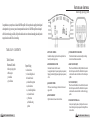
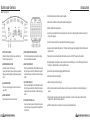
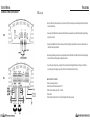
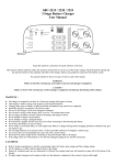
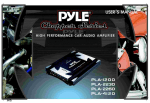
Lanzar Audio Inc.
1600 63rd Street, Brooklyn, NY 11204
(718) 236-8000
www.lanzar.com
Fe ature s and Co ntro ls
M X A 2 3 2 /2 42 /2 52 /2 8 2
Congratulations on your purchase of a Lanzar MAX PRO amplifier. You have purchased a quality product designed
and engineered to give you many years of uncompromised musical service. MAX PRO amplifiers are designed
with the latest technology available, which provides headroom for even the most demanding peaks and dynamic
ranges found on modern CD's and recordings.
TABLE
OF
CONTENTS
Table of Contents
Feature and Controls
1. MXA 232/242/252/282
2. MXA 412/422
3. Installation
4. Specifications
Max Pro Owner’s Manual
1. INPUT LEVEL CONTROLS
Enables the matching of input levels to the output levels from
head unit (or other signal source).
System Wiring
6. 2 channel stereo
7. 2 channel bridged mode
8. 2 channel tri-mode
9. 2 channel triamp system
10. 4 channel stereo
11. 4 channel bridged mode
12. 4 channel tri-mode
13. Precautions
14.Troubleshooting
15.Notes
2. CROSSOVER MODE SELECTOR
Determines the mode of built-in crossover:
low pass (permits only low frequency signals to pass to speakers),
high pass (permits only high frequency signals to pass to speakers),
or flat.
3. BASS BOOST CONTROL
With a bass boost switch engaged, the bass level is increased
approx 18dB.
4. REMOTE BASS BOOST
Plug in the remote bass boost control wire in here
5. POWER & PROTECTION INDICATORS
Provide instant information on status of amplifier, including
short-circuit and thermal overload alerts.
6. HIGH PASS FILTER (HPF)
When Crossover Mode Selector is in High Pass Mode, this control
limits the frequencies which will be distributed to the speakers
to those below the value to which this is set within the range 802.5KHz.
7. LOW PASS FILTER (LPF)
When Crossover Mode Selector is in Low Pass Mode, this control
limits the frequencies which will be distributed to the speakers
to those below the value to which this is set within the range 35400Hz.
8. PHASE SHIFT CONTROL 0-180
Allows you to change the phase of your high and low crossover
from 0 to 180 degrees to help compensate for timing difference
between drivers.
Max Pro Owner’s Manual - 1
Fe ature s and Co ntro ls
Insta l l ation
M X A 41 2 /42 2
1. Find a suitable location in the vehicle to mount the amplifier.
2. Make sure there is sufficient air flow around the intended mounting location.
3. Bolt the amplifier to the mounting surface.
4. Connect the power ground terminal to the nearest point on the chassis of the car. Keep this ground wire less than one meter (39")
in length. Use 8 gauge wire.
5. Connect the remote terminal to the remote output of the head unit using 14 gauge wire.
1. INPUT LEVEL CONTROLS
Enables the matching of input levels to the output levels from
head unit (or other signal source).
2. CROSSOVER MODE SELECTOR
Determines the mode of built-in crossover:
low pass (permits only low frequency signals to pass to speakers),
high pass (permits only high frequency signals to pass to speakers),
or flat.
3. BASS BOOST CONTROL
With a bass boost switch engaged, the bass level is increased
approx 18dB.
4. REMOTE BASS BOOST
Plug in the remote bass boost control wire in here
5. POWER & PROTECTION INDICATORS
Provide instant information on status of amplifier, including
short-circuit and thermal overload alerts.
6. HIGH PASS FILTER (HPF)
When Crossover Mode Selector is in High Pass Mode, this control
limits the frequencies which will be distributed to the speakers
to those below the value to which this is set within the range 802.5KHz.
7. LOW PASS FILTER (LPF)
When Crossover Mode Selector is in Low Pass Mode, this control
limits the frequencies which will be distributed to the speakers
to those below the value to which this is set within the range 35400Hz.
8. PHASE SHIFT CONTROL 0-180
Allows you to change the phase of your high and low crossover
from 0 to 180 degrees to help compensate for timing difference
between drivers.
2 -
Max Pro Owner’s Manual
6. Connect an empty fuse holder within 300mm (12") of the battery and run 8 gauge of larger high quality cable from this fuse to the
amplifier location.
7. Make sure there is no fuse in this fuse holder. Then make the connection to the "BATT" connection on the amplifier.
8. If multiple amplifiers are being used, use cables (each with its own fuse at the battery) or a #0 or #2 cable from the fuse holder at
the battery to a distribution block at or near the amplifier's location.
9. Connect all line inputs and outputs using high-quality RCA-RCA cables.
10. Insert fuse(s) at the battery fuse holder(s).
11. Recheck all connections before powering up.
12. Set all level controls to their least sensitive positions and set all crossover controls, switches, etc. to the desired frequency or
position.
13. Once the system is powered up, set the volume control on the head unit to about the 2 o'clock position, and then set all the
amplifiers' level controls for maximum output level.
14. Further fine tuning of the various controls may be necessary to obtain the desired results.
Max Pro Owner’s Manual - 3
S pec ific ations
MODEL
RMS at 4 Ohms
MAX at 4 Ohms
At 4 Ohms Bridged
RMS at 2 Ohms
Min. Speaker Impedance
T.H.D.
Frequency Response
Input Sensitivity
Input Impedance
S/N Ratio
Channel Separation
Crossover Filters
Low Pass
High Pass
Bass Boost
Dimensions (WxHxL)
Fuse(s)
4 -
Max Pro Owner’s Manual
S pec ific ations
channel
MXA 232 2amplifier
channel
MXA 242 2amplifier
channel
MXA 252 2amplifier
channel
MXA 282 2amplifier
channel
MXA 412 4amplifier
channel
MXA 422 4amplifier
2 x 75W
2 x 125W
2 x 200W
2 x 300W
4 x 35W
4 x 75W
2 x 500W
2 x 800W
2 x 1200W
2 x 2000W
4 x 250W
4 x 500W
1 x 1000W
1 x 1600W
1 x 2400W
1 x 4000W
2 x 500W
2 x 1000W
2 x 100W
2 x 200W
2 x 300W
2 x 450W
4 x 55W
4 x 120W
2 ohm
2 ohm
2 ohm
2 ohm
2 ohm
2 ohm
0.04%
0.04%
0.04%
0.04%
0.04%
0.04%
15Hz-35KHz, -1dB
15Hz-35KHz, -1dB
15Hz-35KHz, -1dB
15Hz-35KHz, -1dB
15Hz-35KHz, -1dB
15Hz-35KHz, -1dB
250mV-5000mV
250mV-5000mV
250mV-5000mV
250mV-5000mV
250mV-5000mV
250mV-5000mV
22 Kohm
22 Kohm
22 Kohm
22 Kohm
22 Kohm
22Kohm
>90dB
>90dB
>90dB
>90dB
>90dB
>90dB
>65dB
>65dB
>65dB
>65dB
>65dB
>65dB
35Hz-400Hz
80Hz-2.50KHz
35Hz-400Hz
80Hz-2.50KHz
35Hz-400Hz
80Hz-2.50KHz
35Hz-400Hz
80Hz-2.50KHz
35Hz-400Hz
80Hz-2.50KHz
35Hz-400Hz
80Hz-2.50KHz
+18dB
+18dB
+18dB
+18dB
+18dB
+18dB
10.47"x2.46"x12"
10.47"x2.46"x15"
10.47"x2.46"x19"
10.47"x2.46"x21"
10.47"x2.46"x12"
10.47"x2.46"x17"
20A
30A
25Ax2
35Ax2
20A
20Ax2
Max Pro Owner’s Manual - 5
Syste m Wir ing
2 CHANNEL STEREO CONFIGURATION
6 -
Syste m Wir ing
MXA 232/242/252/282
MXA 232/242/252/282
2 CHANNEL BRIDGED MODE CONFIGURATION
FRONT
FRONT
REAR
REAR
Max Pro Owner’s Manual
Max Pro Owner’s Manual - 7
Syste m Wir ing
2 CHANNEL TRI-MODE CONFIGURATION
Syst e m Wi r i ng
MXA 232/242/252/282
MXA 232/242/252/282
TRIAMP SYSTEM USING THREE 2 CHANNEL AMPLIFIERS
FRONT
REAR
8 -
Max Pro Owner’s Manual
Max Pro Owner’s Manual - 9
Syst e m Wi r i ng
4 CHANNEL STEREO CONFIGURATION
10-
Syst e m Wi r i ng
MXA 412/422
MXA 412/422
4 CHANNEL BRIDGED MODE CONFIGURATION
FRONT
FRONT
REAR
REAR
Max Pro Owner’s Manual
Max Pro Owner’s Manual -11
Syst e m Wi r i ng
4 CHANNEL TRI-MODE CONFIGURATION
Precautions
VIBE 412/422
• Before you drill or cut any holes, investigate your car's layout very carefully. Take care when your work near the gas tank, fuel lines, hydraulic
lines and electrical wiring.
FRONT
• Do not operate the amplifier when it is unmounted. Attach all audio system components securely within the automobile to prevent damage,
especially in an accident.
• Do not mount this amplifier so that the wire connection, or likely to be damaged by nearby objects. Be sure to select a location inside your
vehicle which has adequate ventilation.
• Before making or breaking power connections in your system, disconnect the vehicle battery. Confirm that your head unit or other equipment
is turned off while connecting the input jacks and speaker terminals.
• If you need to replace the power fuse, only replace it with a fuse indentical to that supplied with the system. Using a fuse of a different
type or rating may result in damage to your system which isn't covered by the manufacturer's warranty.
REAR
12-
A mpl i f i er Wi l l Not P ower U p.
• Check for good ground connection.
• Check that remote DC terminal has at least 12V DC.
• Check that there is battery power on the "+" terminal.
• Check all fuses.
• Check that Protection LED is not lit. If it is lit, shut off amplifier briefly and then repower it.
Max Pro Owner’s Manual
Max Pro Owner’s Manual -13
Tr o u b l e sho ot i ng
Notes
Hi g h Hi s s O r E n g i n e N oi s e (A lter n ator Wh i n e) I n S peak er s .
• Disconnect all RCA inputs to the amplifier(s)-if hiss/noise disappears, then plug in the component driving the amplifier and unplug its
inputs. If hiss/noise disappears, go on until the faulty/noisy component is found.
• It is best to set the amplifier's input level as low as possible. The best subjective S/N ratio is obtainable this way. Try to drive as high a
signal level from the head unit as possible.
Pr otecti on Led Comes O n Wh en Th e A mpl i f i er I s P ower ed U p
• Check for shorts on speaker leads.
• Check that the volume control on the head unit is turned down low.
• Remove speaker leads, and reset the amplifier. If the Protection LED still comes on, then the amplifier is faulty.
A mpl i f i er (S ) Gets Very Hot
• Check that the minimum speaker impedance for that model is correct.
• Check for speaker shorts.
• Check that there is good airflow around the amplifier. In some appliciations, an external cooling fan may be required.
Di storted S oun d
• Check that the level control(s) is set to match the signal level of the head unit.
• Check that all crossover frequencies have been properly set.
• Check for shorts on the speaker leads.
Hi g h S queal N oi s e Fr om S peak er s
• This is almost always caused by a poorly-grounded RCA patch cord.
14-
Max Pro Owner’s Manual
Max Pro Owner’s Manual -15