1
HEATING
& COOLING
3-Phase Single-Packaged
50ZP036-060
Air Conditioners
Visit "vv'vv'vv.
12_lrri_r.L"
oin
installation, Start-Up and Service instructions
NOTE: Read the entire instruction
installation.
manual belk_re starting the
TABLE OF CONTENTS
SAFETY CONSIDERATIONS .....................................................
l
INTRODUCTION
2
..........................................................................
RECEIVING AND INSTALLATION
..........................................
Check Equipment ......................................................................
IDENTIFY UNIT ................................................................
INSPECT SHIPMENT ........................................................
2
2
2
2
Provide Unit Support ................................................................
2
SLAB MOUNT ...................................................................
2
Provide Clearances ....................................................................
2
Place Unit ..................................................................................
2
Select and Install Ductwork .....................................................
2
INSTALL FLANGES FOR DUCTWORK
CONNECTIONS (50ZPI)6t) ONLY) ...................................................
2
CONVERTING HORIZONTAL DISCHARGE UNITS TO
DOWNFLOW (VERTICAL) DISCHARGE ...................... 6
Provide lk_rCondensate Disposal ............................................. 6
Install Electrical Connections ...................................................
7
HIGH-VOLTAGE CONNECTIONS .................................. 7
ROUTING POWER LEADS INTO UNIT ........................ 8
CONNECTING GROUND LEAD TO UNIT GROUND.8
ROUTING CONTROL POWER WIRES .......................... 8
ACCESSORY ELECTRIC HEAT WIRING ..................... 8
SPECIAL PROCEDURES FOR 208-V OPERATION .....8
PRE-START-UP
............................................................................
9
START-UP .....................................................................................
9
Check lor Refl'igerant Leaks ....................................................
9
LOCATE AND REPAIR REFRIGERANT LEAKS AND
CHARGE THE UNIT AS FOLLOWS: ............................. 9
Start-Up Cooling Section and Make Adjustments ................ 10
CHECKING COOLING CONTROL OPERATION ....... 10
Refrigerant Charge ..................................................................
10
NO CHARGE ....................................................................
10
LOWCHARGE COOLING ...............................................
10
TO USE COOLING CHARGING CHARTS .................. 10
Indoor Airflow and Airflow Adjustn-ients .............................. 10
FOR 208/230-V .................................................................
11
FOR 460-V MOTORS ......................................................
11
Unit Controls ...........................................................................
ll
HIGH-PRESSURE RELIEF VALVE ............................... 11
COMPRESSOR OVERLOAD .......................................... 11
Sequence of Operation ............................................................
11
FAN OPERATION ............................................................
11
COOLING ..........................................................................
11
HEATING ..........................................................................
11
MAINTENANCE .........................................................................
Air Filter ..................................................................................
Unit Top Removal (Condenser-Coil
Manufacturer
reserves
PC 101
the right
12
16
Side) ............................ 16
to discontinue,
Printed in U.S.A.
or change
C00155
Fig. liUnit
50ZP
Evaporator Blower and Motor ................................................
Condenser Coil, Evaporator Coil, and Condensate Drain Pan.
Condenser Fan ........................................................................
Electrical Controls and Wiring ...............................................
Reli"igerant Circuit ..................................................................
Evaporator Airflow .................................................................
Metering Devices ....................................................................
Liquid Line Strainer ................................................................
TROUBLESHOOTING
...............................................................
16
16
17
18
18
18
18
18
18
START-UP CHECKLIST ............................................................
18
NOTE TO 1NSTALLER--Belk_re installation, READ THESE
INSTRUCTIONS
CAREFULLY AND COMPLETELY. Also,
make sure the User's Manual and Replacement Guide are leli with
the unit after installation.
SAFETY CONSIDERATIONS
Installation and servicing of air-conditioning equipment can be
hazardous due to systen-i pressure and electrical components. Only
trained and qualified workers should install, repair, or service
air-conditioning equipment.
Untrained workers can perlkmn basic maintenance l_.lnctions of
cleaning coils and lilters. All other operations should be perlbm_ed
by trained service people. When working on air-conditioning
equipment, pay attention to precautions in the literature, tags, and
labels attached to the unit, and other salk:ty precautions that may
apply.
Follow all sallcty codes. Wear sal_:ty glasses and work gloves. Use
quenching cloth lk_r unbrazing operations. Have flrc extinguisher
available Ik_rall brazing operations.
at any time, specifications
Catalog No. 50ZP-5SI
or designs
without notice
Pg 1
and without
2-06
incurring obligations.
Replaces:
New
Step
The
Beliwe perlimning service or maintenance operations on
system, mm off main power to unit. Turn o11'accessory heater
power switch if applicable. Electrical shock can cause serious
injury or death.
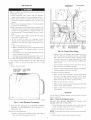
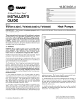
3--Provide
required
combustibles
condenser
The
minimmn
are
shown
service
clearances
in Fig.
2-4.
and
Adequate
clearances
to
ventilation
and
air naust be provided.
condenser
discharges
Clearances
fan
pulls
it through
air
through
the
the fan on the top cover.
condenser
coil
and
Be sure that the fan
Recognize salety in%rmation. This is the sali_ty-alert symbol ,/_.
When yon see this symbol in instructions or manuals, be alert to
the potential lkw personal injury.
discharge does not recirculate to the condenser
coil. Do not locate
the unit in either a corner or under an overhead obstruction.
The
Understand the signal words DANGER, WARNING, CAUTION,
and NOTE. These words are used with the sali:ty-alert symbol.
DANGER identifies the most serious hazards which will result in
severe personal injury or death. WARNING signifies a hazard
which could result in personal injury or death. CAUTION is used
to identily unsali: practices which would result in minor personal
injury or product and property danmge. NOTE is used to highlight
suggestions which will result in enhanced installation, reliability,
or operatkm.
house
These instructions cover mininmm requirements and cnnlorm to
existing national standards and salety codes. In some instances,
these instructions exceed certain local codes and ordinances,
especially those that nmy not have kept tap with changing residential construction practices. We require these instructions as a
mininmm liw a sail: installation.
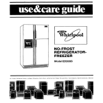
INTRODUCTION
50ZP cooling units arc lhlly self-contained and designed lk)r
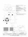
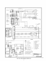
outdoor installation. (See Fig. 1.) As shown in Fig. 2-4, units are
shipped in a horizontal-discharge configuration lor installation on
a ground-level slab. All units can be field-converted to downflow
discharge configurations lor rooBop applications with a fieldsupplied plenum.
RECEiViNG AND iNSTALLATiON
Step 1--Check
Equipment
mininnma
horizontal
inches.
Inspect liw shipping danmge while unit is still on shipping pallet.
I1' unit appears to be damaged or is torn loose from its securing
points, have it examined by transportation inspectors belk)re
removal. Forward claim papers directly to transportation company.
Manufacturer is not responsible lk)rany damage incurred in transit.
Check all items against shipping list. Immediately notily the
nearest Carrier Air Conditioning office il' any item is missing.
To prevent loss or damage, leave all parts in original packages
until installation.
Step 2--Provide
Unit Support
SLAB MOUNT
Place the unit on a rigid, level surl'ace, suitable to support the unit
weight. The fiat surface should extend approxinmtely 2-in. beyond
the unit casing on the 2 sides. The duct connection side and
condensate drain connection sides should be flush with the edge of
the flat surface. A concrete pad or a suitable fiberglass mounting
pad is rccnmmended.
A 6-in. wide gravel apron should be used around the fiat surface to
prevent airflow blockage by grass or shrubs. Do not secure the unit
to the flat surface except where required by local codes.
The unit should be level to within 1/4 inch. This is necessary lkw
the unit drain to function properly.
under
is 48
extension
Do not restrict
a partial
overhang
in. above
ol' a partial
condenser
the
unit
overhang
airflow.
(such
as a nornml
top.
The
must
not exceed
An air restriction
the outdoor-air
inlet or the fan discharge
coFilpressor lili:.
nmximum
48
at either
can be harmful
to
Do not place the unit where water, ice, or snow l]'ona
an overhang
or roof will danmge or flood the unit. The unit may be installed on
wood flooring or on Class A, B, or C roof covering materials.
Step 4--Place
Unit
Unit can be moved with the handholds provided in the unit
basepan. Relier to Table 1 lor operating weights. U_se extreme
caution to prevent rlamage when moving the unif. Unit nlu,_t
remain in an 1q)right position during all tooling operations. The
unit must be level li)r proper condensate drainage; the ground-level
pad nmst be level beli_we setting the unit in place. When a
field-fabricated support is used, be stare that the support is level
and that it properly supports the unit.
Step 5--Select
and Install
The design and installation
accordance with:
Duetwork
ol' the duct
system must
be in
•
the standards of the NFPA (National Fire Protection Association) lor installation of nonresidence-type air conditioning and
ventilating systems
•
NFPA90A or residence-type, NFPA90B; and/or local codes
and residence-type, NFPA 90B
•
and/or local codes and ordinances
IDENTIFY UNIT
The unit model number and serial number am stamped on the unit
identification plate. Check this inlornmtion against shipping papers.
INSPECT SHIPMENT
clearance
overhang)
Select and size ductwork, supply-air registers and return-air grilles
according to ASHRAE (American Society of Heating, Refrigeration, and Air Conditkming Engineers) recommendations.
Use the duct flanges provided on the supply- and return-air
openings on the side of the unit. See Fig. 2-4 lor connection sizes
and locations. The 14-in. round duct collars (size 036-048 units)
are shipped inside the unit attached to the indoor blower. They are
field-installed and nmst be removed frona the indoor cavity prior to
start-up, even if they are not used lor installation.
INSTALL FLANGES
(50ZP06t) ONLY)
FOR
DUCTWORK
The 51)ZP060 units are shipped
field-installed on the unit.
with flanges
CONNECTIONS
which must be
To install unit flanges:
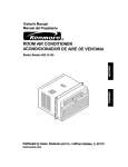
1. Five pieces of flange are shipped on the return-air opening of
the unit. Remove the flanges li"om the shipping position. See
Fig. 5. Screws arc field-supplied.
2. One piece of flange is used as it is shipped (straight). Bend the
other 4 pieces at right angles.
3. Install the straight flange Oll the right side of the return-air
opening in holes provided. See Fig, 6. Flanges should stick out
fi'om unit to allow lk)r connection of ductwork.
[
,/]
r'94
,3
16 06]
REQUIRED
_
CLEARANCE
TO COMBUSTIBLE
MATE
_4080
INCHES [mini
0
0
0
0
TOP QF UNIT .........................................................................................
DUCT SIDE QF UNIT .............................................................................
SIDE OPPOSITE DUCTS ......................................................................
BOTTOM OF UNIT .................................................................................
NEC.
REQUIRED
CLEARANCES.
INCHES
BETWEEN UNITS, POWER ENTRY SIDE ....................................
42.00
UNIT AND UNGROUNDED
SURFACES, POWER ENTRY SIDE .36.00
UNIT AND BLOCK OR CONCRETE
WALLS AND OTHER
GROUNDED
SURFACES, POWER ENTRY SIDE ......................... 42.00
[mini
[1666.8]
[914.01
[1066.8]
[
REQUIRED
</
[95
CLEARANCE
FOR
OPERATION
AND
SERVICING
INCHES [mm]
36.06 [762.01
36.08 [762.0]
CONDENSER
COIL ACCESS SIDE ..............................................
POWER ENTRY SIDE ....................................................................
(EXCEPT FOR NEC REQUIREMENTS)
UNIT TQP .......................................................................................
SIDE OPPOSITE DUCTS ..............................................................
!
48.0011219.21
36.00 1762.0]
LEGEND
NEC
National
Electrical
Code
NOTES:
1. Clearances
must be maintained
to prevent recirculation of air from outdoorfan discharge, with the exception of the condenser
coil (36.00 in [914.0 mini. A
removable fence or barricade requires no clearance.
2.
Dimensions
are in inches.
Dimensions
in [ ] are in millimeters.
II
CON;)
¢0
N\
\\
°1o
BI OWER, CONTROl
ACC{SS PANEL
COMPRESSOR
BOX AND EVAP
PANEL
COli
\
\\\\\\
FIELD
ENTRY
SERVICE
TO\
PORTS
_\
\\\
LEFT SIDE VIEW
'°6 L
FRONT VIEW
[I
26.772
[10540]
I.D.
20]
; L6,.,,2.,o
_1]
x 12.7 DEEP
RIGHT SIDE VIEW
C00156
UNIT
50ZP036
ELECTRICAL
CHARACTERISTICS
UNIT WEIGHT
Ib
250
208/230-3-60
Fig. 2--Unit
kg
114
Base Dimensions,
CENTER OF GRAVITY
IN.
X
Y
Z
355.6 (14.00)
508.0 (20.00)
241.3 (9.50)
50ZP0036
_ii:sis
_29S
LI6:oeJ
0
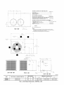
REQUIRED
CLEARANCE
TO COMBUSTIBLE
_IATL.
INCHES [mm]
TOP OF UNIT .........................................................................................
0
DUCT SIDE OF UNIT .............................................................................
0
SIDE OPPOSITE DUCTS ......................................................................
0
BOTTOM OF UNIT .................................................................................
0
408 0
NEC. REQUIRED
CLEARANCES.
INCHES [mm]
BETWEEN UNITS, POWER ENTRY SIDE .................................... 42.00 1066.8
UN T AND UNGROUNDED SURFACES, POWER ENTRY S DE .36.00 9 4.0
UNIT AND BLOCK OR CONCRETE WALLS AND OTHER
GROUNDED SURFACES, POWER ENTRY SIDE ......................... 42.00 [1066.81
REQUIRED
CLEARANCE
FOR OPERATION
AND SERVICING
INCHES [mm]
CONDENSER COIL ACCESS SIDE ..............................................
POWER ENTRY SIDE ....................................................................
(EXCEPT FOR NEC REOUIREMENTS)
UNIT TOP .......................................................................................
S DE OPPOS TE DUCTS ..............................................................
247 6
i9 75]
30.60 [762.0]
30.00 [762.0]
48.00 1219.2
30.60 762.0
LEGEND
NEC - National Electrical Code
REAR VIEW
3560
b, _
{4
{',
[}[ '," I 0 [ ' t ( 8
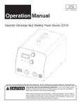
NOTES:
1. Clearances must be maintained to prevent recirculation of air from ouMoor1an discharge, with the exception ol the condenser coil (36.00 in [914.0 mm]. A
removable fence or barricade requires no clearance.
2. Dimensions are in inches. Dimensions in [ ] are in millimeters.
12950
i5098]
50TTOM OF UNiT
EVS_PC,
R,_ICR _
CO_L
COND 5SfiR
CO_
N,
\
%4 I
H
I
m
I
i_
8i2
i
ir
[[CdiER,
',APORAI',}R
COMPRESSOR
CCNIRO[ DO'( AND
COIl ACC SS P##Ei
PANEL
\
i
LEFT SIDE VIEW
FRONT VIEW
6tiC
[250]
, 0_0_
RIGHTSIDE VIEW
C00003
UNIT
ELECTRICAL
UNIT WEIGHT
CHARACTERISTICS
50ZP042
208/230-3-80
50ZP048
208/230-3-80
OF GRAVITY
IN.
kg
X
Y
Z
297
135
355.8 (14.00)
508.0 (20.00)
304.8 (12.00)
355.8 (14.00)
508.0 (20.00)
304.8 (12.00)
310
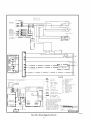
Fig. 3--Unit
CENTER
Ib
Base
141
Dimensions,
50ZP042_48
DIMENSIONS IN [] ARE IN INCHES
_35217
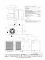
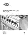
REQUIRED
[IBIB9]
1176
[465]
_3528
_537
[1389]
CLEARANCETO
COMBUSTIBLE
MATL.
TOP OF UNIT .........................................................................................
DUCT SIDE OF UNIT .............................................................................
SIDE OPPOSITE DUCTS ......................................................................
BOTTOM OF UNIT .................................................................................
[211]
INCHES [mini
0
0
0
0
NEC.
REQUIRED
CLEARANCES.
INCHES
BETWEEN UNITS, POWER ENTRY SIDE ....................................
42.00
UNIT AND UNGROUNDED
SURFACES, POWER ENTRY SIDE .36.00
UNIT AND BLOCK OR CONCRETE
WALLS AND OTHER
GROUNDED
SURFACES, POWER ENTRY SIDE ......................... 42.00
REQUIRED
706
[27 80]
CLEARANCE
FOR OPERATION
AND
[1066.8]
SERVICING
INCHES [mr:l]
30.00 [762.0]
30.00 [762.0]
CONDENSER
COIL ACCESS SIDE ..............................................
POWER ENTRY SIDE ....................................................................
(EXCEPT FOR NEC REQUIREMENTS[
UNIT TOP .......................................................................................
SIDE OPPOSITE DUCTS ..............................................................
3525
88]
[mmI
[1066.8]
[914.0]
48.00 [1219.21
30.00 [762.0]
LEGEND
3.5
44]
O
L
n
889
REAR VIEW
NEC
J
[350]
Electrical
Code
1. Clearances
must be maintained to prevent recirculation of air from outdoorfan discharge, with the exception of the condenser coil (36.00 in [914.0 mini. A
removable fence or barricade requires no clearance.
2.
12950
[50198]
BOTTOM OF UNIT
EVAP.
National
NOTES:
Dimensions
are in inches.
Dimensions
in [ ] are in millimeters.
t
COND,
COIL_
81215
[31199]
BOTTOM OF UNIT
I
\\\
ACCESS
CONTROL BOX AND EVAP
PANEL
//
C01L
690
[272]
COMPRESSOR PANELFIEL
D
_5490
[2161]
NTRYTO
\
o
/
iioooo-0
LEFT SIDE VIEW
FRONT VIEW
2o772
[I
UNIT
50ZP06O
ELECTRICAL
CHARACTERISTICS
208/230-3-60,
460-3-80
Fig. 4--Unit
I.D.
0540]
UNIT WEIGHT
Ib
350
kg
159
Base Dimensions,
RIGHT SIDE VIEW
CENTER
OF GRAVITY
C00158
IN.
X
Y
Z
385.6 (14.00)
508.0 (20.00)
355.6 (14.00)
50ZP060
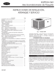
4. Install 2 laand-lbrmed
provided
5. Install
to li)rm
remaining
opening
2 hand-lkmned
and installing
connecting
3/4 inch
damaged.
around
in boles
air opening.
discharge
air
area
to flanges.
ductwork,
ductwork
in shaded
All units
return-air
consider
the lbllowing:
to units, do not drill deeper
shown
in Fig.
7 or coil
than
may
be
should have field-supplied
filters installed
in the
side ol' the unit. Recommended
sizes lot filters are
shown
in Table
Avoid
I.
abrupt duct size increases
in duct size adversely
al'li:cts
IMPORTANT:
Use
unit to prevent
transmission
ensure
air opening
the return
flanges
can now be attached
designing
When
onto return
around
in holes provided.
6. Ductwork
When
flanges
a rectangle
weathertight
flexible
and reductions.
connectors
between
of vibration.
and airtight
Abrupt
change
Use
ductwork
suitable
limit
switches
STRAIGHT
and
gaskets
C00006
Fig. 6--Flanges
seal.
may trip
at air quantities
below
PIECE
to
Size ductwork lot cooling air quantity (clan). The minimum
air
quantity lbr proper electric beater operation is listed in Table 2.
Heater
HAND FORM
air performance.
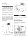
CONVERTING
Installed
on 50ZP060 Units
HORIZONTAL
DOWNFLOW
(VERTICAL)
DISCHARGE
UNITS
TO
DISCHARGE
those
recommel'ided.
Insulate and weatherprool'
all external ductwork.
Insulate and
cover with a vapor barrier
all ductwork
passing
through
Belore
conditioned
spaces.
tioning Contractors
systeln, turn olT main power to unit. Turn off accessory beater
power switch if applicable.
Electrical shock can cause serious
Follow latest Sheet
National Association
Metal and Air Condi(SMACNA)
and Air
Conditioning
Contractors
Association
(ACCA) mininmm
installation standards lk}r residential
beating and air conditioning
systenls.
Secure
injury
all ducts to building
8 shows
structure.
duct openings
practices.
a typical
Flash,
in wall
duct system
weatherproof,
or roof
according
and
Units are dedicated
convert
service
or
maintenance
operations
on
or death.
to vertical
vibration-isolate
good construction
Figure
perlbrming
side supply
air supply.
to vertical
products.
They are not convertible
A field-supplied
plenum
must
be used
to
air discharge.
to
Step
with 50ZP unit installed.
6--Provide
NOTE:
Disposal
Be sure that condensate-water
with local
Unit
for Condensate
codes,
removes
restrictions,
condensate
located
at the end of
condensate
connection.
through
the
disposal
methods
comply
and practices.
unit.
a 1-3/64-in.
See
Fig.
1D bole which
2-4
lot
location
is
of
C00007
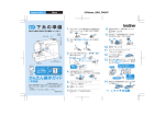
FIVE PIECES OF DUCT
FLANGE ATTACHED
HERE FOR SHIPMENT
COOOO5
Fig. 5--Shipping
Location of Duct Flanges
(Size 060 Only)
Fig. 7--Area
Not to Be Drilled More Than 3/4-in.
Condensate
water can be drained
installations
(where
level installations.
permitted)
directly
onto the roof in rooftop
or onto a gravel
Install a Held-supplied
condensate
connection
to ensure
the outlet
of the trap
is at least
proper
apron
condensate
drainage.
1 in. lower
in ground-
trap at end of
Make
sure that
than the drain-pan
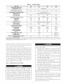
Table
1 --
Physical
Data
UNiT 50ZP
036
042
OPERATING WEIGHT {Ibs)
COMPRESSOR TYPE
250
297
REFRIGERANT
REFRIGERANT
Charge
METERING
(Ib)
EVAPORATOR
4.7
COiL
3...18
3.1
EVAPORATOR FAN MOTOR
Blower Motor Size (in.)
Nominal Cfm
Rpm Range
Number of Speeds
Factory Speed Setting
Motor Hp
10x8
1200
800-1050
3
Low
1/2
350
4.4
__
8.1
AcutroFM Device
[
Copper Tubes, Aluminum Plate Fins
3...15
3...15
3.9
4.3
Direct Drive
10x9
10x9
1400
1800
800-1050
1000-1100
3
2
Med
Low
1/2
3/4
Round
14
14
DUCT SIZES
Supply Air (in.)
Return Air (in.)
FIELD-SUPPLIED RETURN-AIR
Throwaway (in.)
310
7.5
Copper Tubes, Aluminum Plate Fins
1...17
2...17
11.1
8.8
Propeller
2600
2600
1100
1100
1/4
1/4
20
20
2OOO
1100
1/4
2O
Rows... Fins/in.
Face Area (sq ft)
CONNECTING
J
2...17
8.2
CONDENSER-FAN
MOTOR CFM
Nominal Rpm
Motor Hp
Diameter (in,)
060
Reciprocating
DEVICE
CONDENSER COiL
Rows... Fins/in.
Face Area {sq ft)
048
2...17
10.7
28OO
1100
1/4
2O
4...15
4.9
10 x 10
1850
950-1100
3*,2*
Low
1
Square
13.9 x 13.9
13.9 x 27.8
/
FILTERt
24 x 24
1
24 x 24
|
Z
24 x 30
24 x 30
* 460-v motors are 2-speed or 3-speed.
tRequired filter sizes shown are based on the ARI (Air Conditioning
for high capacity type. Recommended
filters are 1-in. thick.
and Refrigeration
condensate connection to prevent the pan b*Oln overflowing. See
Fig. 9 and 10. Prime the trap with water. When using a gravel
apron, make sure it slopes away li"om the unit.
If the installation requires draining the condensate water away
from the unit, install a 2-in. trap using a 3/4-in. OD robing or pipe.
(See Fig. 9 and 10.) Make sure that the outlet of the trap is at least
1 in. lower than the unit drain-pan condensate connection to
prevent the pan li"om overflowing. Prime the trap with water.
Connect a drain tube using a minimum of 314-in. PVC, 314-in.
CPVC, or 3/4-in. copper pipe (all field supplied). Do not undersize
the tube. Pitch the drain tube downward at a slope of at least 1 in.
%r every 10 11of horizontal run. Be sure to check the drain tube
%r leaks. Prime trap at the beginning of the cooling season
start-up. Allowable glues lbr condensate trap connection are:
Standard ABS, CPVC, or PVC cement.
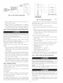
Step 7--Install
Electrical
Connections
The unit cabinet nmst have an uninterrupted, unbroken
electrical ground to minimize the possibility of personal
injury if an electrical fault should occur. This ground may
consist of an electrical wire connected to the unit ground in
the control compamnent, or conduit approved lot electrical
ground when installed in accordance with NEC (National
Electrical Code), ANSI (American National Standards
lnstitute)/NFPA (latest edition) (in Canada, Canadian Electrical Code CSA C22.1) and local electrical codes. Failure to
adhere to this warning could result in serious injury or death.
Institute) rated airflow at a velocity of 300 ft/min for throwaway
W
.
type or 450 ft/min
t!
Failure to R_llow these precautions could result in damage to
the unit being installed:
1. Make all electrical connections in accordance with NEC
ANSI/NFPA (latest edition) and local electrical codes
governing such wiring. In Canada, all electrical connectiens nmst be in accordance with CSA standard C22.1
Canadian Electrical Code Part 1 and applicable local
codes. Relier to unit wiring diagram.
2. Use only copper conductor %r connections between
field-supplied electrical disconnect switch and unit. DO
NOT USE ALUMINUM WIRE.
3. Be sure that high-voltage power to unit is within operating
voltage range indicated on unit rating plate.
4. Insulate low-voltage wires %r highest voltage contained
within conduit when low-voltage control wires are run in
same conduit as high-voltage wires.
5. Do net damage internal components when drilling through
any panel to mount electrical hardware, conduit, etc. On all
3-phase units, ensure phases are balanced within 2 percent.
Consult local power company %r correction of improper
voltage and/or phase imbalance.
HIGH-VOLTAGE
CONNECTIONS
The unit nmst have a separate electrical service with a fieldsupplied, waterproof disconnect switch mounted at, or within sight
from the unit. Relier to the unit rating plate lk_r maximum
fuse/circuit breaker size and mininmm circuit amps (ampacity) lot
wire sizing. See Table 3 lbr electrical data.
The field-supplied disconnect may be mounted on the unit over the
high-voltage inlet hole. See Fig. 2-4.
conduit termination at the unit must be watertight. Run the
high-voltage leads through the hole on the control box side of the
unit (see Fig. 11 l_)r location). When the leads are inside the unit,
run leads to the control box (see Fig. 12). On 3-phase units,
connect the leads to the black, yellow, and blue wires (see Fig. 13.)
CONNECTING
GROUND LEAD TO UNIT GROUND
Refer to Fig. 12 and 13. Connecl the ground lead to the chassis
using the unit ground lug in the conlrol box.
ROUTING
CONTROL POWER WIRES
Form a drip-loop with the thermostat leads belk)re routing them
into the unit. Route the thermostat leads through grommeted hole
provided in unit into unit control box. (See Fig. 11.) Connect
thermostat leads to unit control power leads as shown in Fig. 14.
*S÷pa_atedlscgnneet per NEC
/NationalElectrlcal Code/ required
forelectrr¢ heateļ _,nen Ongle
pointcone_t_onIs not use_
Fig. 8--Typical
C00008
installation
Route thermostat wires through grommet providing a drip-loop at
the paneh Connect low-voltage leads to the thermostat as shown in
Fig. 14.
The unit translormer supplies 24-v power liar complete system
including accessory electrical beater. Translk_rmer is factory wired
lk)r 23(1-v operation. If supply voltage is 208 v, rewire translk_rmer
primary as described in the Special Procedures lk)r 2(18-v Operation section below.
1"(25ram) MIN.
TRAP
ACCESSORY
ELECTRIC HEAT WIRING
2" (50ram)MIN. Refer to accessory electric beat installation instructions lk)rinl_)rmarion on installing accessory electric beat. Accessory electric
heat wMng is shown in Fig. 15.
C99013
Fig. 9--Condensate
Trap (Using Tubing)
SPECIAL PROCEDURES
TRAP
OUTLET
!
FOR 208-V OPERATION
vv.
-s
Make sure thai the power supply to the unit is switched OFF
before making any wMng changes. Electrical shock can cause
serious injury or death.
1" min.
2" min.
1. Remove wirenut from connection of ORG wire to BLK wire.
Disconnect the ORG translormer-primary lead from the BLK
wire. Save wimnut. See unit wiring label.
2. Remove the wirenut from the terndnal on the end of the RED
C00009
Fig. lO--Condensate
Table
2--Minimum
Trap (Using
Airflow
for Safe
Operation
lead.
PVC Piping)
3. Save the wirenut.
Electric
4. Connect the RED lead to the BLK wire ff(}nl which the ORG
Heater
lead was disconnected.
(CFM)
Insulate with wirenut from Step 1.
5. Using the wirenut removed fi'om the RED lead, insulate the
loose terminal on the ORG lead.
SIZE
036104210481060
1200
1225
transfl}rmer-primary
1400
1750
Operation
of unit
improperthatline
voltage
and may cause
unitondamage
could
all,c1constitutes
warranty. abuse
ROUTING P()WER LEADS INTO UNIT
Use only copper wire between disconnect and unit. The highvoltage leads should be in a conduit until they enter the unit;
6. Wrap the wirenuts with electrical
terminals cannot be seen.
tape so thai the metal
Indoor blower-motor speeds may need to be chan(_ede f'or 2(18-v
operation. Refer to Indoor Airflow and Airflow Adjnslments
section. (See Table o1' Contents li)r page number.)
PRE-START-UP
COMPRESSOR
CONTACTOR
TRANSFORMER
\
Failure to observe the lollowing warnings could result in
serious inju U or death:
1. Follow recognized sali:ty practices and wear protective
goggles when checking or servicing reb'igerant system.
2. Do not operate compressor or provide any electric power to
unit unless compressor terndnal cover is in place and
secured.
3. Do not remove compressor terminal cover until all electrical sources are disconnected.
4. Relieve all pressure li"om both high- and low-pressure sides
of the system beli)re touching or disturbing anything inside
temfiual box if refrigerant leak is suspected around con>
pressor terminals. Use accepted methods to recover refrigerant.
5. Never attempt to repair soldered connection while refrigerant system is under pressure.
6. Do not use torch to remove any component. System
contains oil and reli"igerant under pressure. To remove a
component, wear protective goggles and proceed as lol-
O
O
©
O
O
o
lows:
a. Shut o1"1electrical power to unit.
b. Relieve all reli"igerant from system using both high- and
low-pressure ports. Use accepted methods to recover
refrigerant.
c. Cut component connecting tubing with tubing cutter and
remove component li"om unit.
d. Carefully unsweat remaining tubing stubs when necessary. Oil can ignite when exposed to torch flame.
ELECTRIC
HEATER
FUSES
INDOOR
FAN
RELAY
OUTDOOR FAN MOTOR
AND COMPRESSOR
START CAPACITOR
Fig. 12--Control
Use the Start-Up Checklist supplied at the end of this book and
proceed as lkHlows to inspect and prepare the unit lk)r initial
start-up:
1. Remove all access panels.
HIGH-VOLTAGE
POWERWIRING
ENTRY HOLE
GROUND
LUG
HIGH
VOLTAGE
LEADS
C00011
Box Wiring
b. Inspect R)r oil at all refrigerant tubing connections and on
unit base. Detecting oil generally indicates a reli"igeraut
leak. Leak-test all reli"igeraut tubing connections using
electronic leak detector, or liquid-soap solution. If a reli"igeraut leak is detected, see l'ollowiug Check for Refrigenmt
Leaks section.
c. Inspect all field- and factory-wiring connections. Be sure
that connections are completed and tight.
d. Inspect coil fins. If damaged during shipping and handling,
carefully straighten fins with a l]u comb.
LOW-VOLTAGE
WIRING ENTRY
HOLE
3. Verify the liHlowing conditions:
a. Make sure that outdoor-fan blade is correctly positioned in
fan orifice. Top edge of blade should be 3.125 in. down
from condenser outlet grille. See Condenser Fan section.
(Reler to the Table of Contents lk)r page number.)
b. Make sure that air filter is in place.
c. Make sure that condensate drain pan and trap are filled with
water to ensure proper drainage.
d. Make sure that all tools and miscellaneous loose parts have
been removed.
START-UP
Use the Start-Up Checklist supplied at the end of this book and
proceed as lollows:
C00010
Fig. 11--Unit
2. Read and lollow
CAUTION,
shipped
Make
the li)llowing
a. Inspect
lines,
instructions
and
with,
Connection
on all DANGER,
INFORMATION
labels
WARNING,
attached
to,
or
inspections:
parts,
LEAKS
AND
1. Using both high- and low-pressure ports, locate leaks and
reclaim remaiuing refrigerant to relieve system pressure.
2. Repair leak lidlowiug accepted practices.
unit.
liar shipping
loose
Electrical
Step 1--Check for Refrigerant Leaks
LOCATE
AND REPAIR REFRIGERANT
CHARGE THE UNIT AS FOLLOWS:
and handling
disconnected
damages
wires,
etc.
such as broken
NOTF: Install a filter drier whenever the systen_ has been opened
liar repair.
3. Check system liar leaks using an approved method.
UNIT GROUND
GROUND
LEAD
SINGLE-PHASE
I_CONNECTIONS
43-PHASE
CONNECTIONS
TO DISCONNECT[ LL_ .....
TO DISCONNECT PER NEC
PER NEC
L ......
Fig. 13--Line
<b
4333
_ Z_
L_RED--4
BLK-
_YEL---_
Power Connections
@
C00012
UNIT CONTROL BOX
THERMOSTAT
AND SUBBASE
Fig. 14--Control
4. Evacuate refrigerant system and reclaim
additional leaks are lound.
refrigerant
if no
Cooling Section
To measure suction pressure, perl_wm the flfllowing:
1. Connect the pressure gauge to the service port on the suction
line.
and Make Adjustments
2. Mount the temperature sensing device on the suction line and
insulate it so that outdoor ambient temperature does not al]bct
the reading. Indoor-air cfin nmst be within the normal operating range of the unit.
Complete the required procedures given in the Pre-Start- Up
section this page belore starting the unit. Do not jumper any
salL'ty devices whelk operating the unit.
Do not operate the compressor when the outdoor temperature
is below 40 ° F.
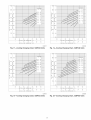
TO USE COOLING CHARGING
what the suction
3. If suction temperature is high, add refrigerant. If suction
temperature is low, carefully recover some of the charge.
CONTROL OPERATION
4. Recheck the suction pressure as charge is adjusted.
EXAMPLE: (Fig. 17)
Outdoor Temperature ................. 85 ° F
Suction Pressure ................. 80 psig
Suction Temperature should be ........ 70 ° F
(Suction Temperature may vary +5°F.)
I. Place room thermostat SYSTEM switch ilk OFF position.
Observe that blower motor starts when FAN switch is placed
in ON position and shuts down when FAN switch is placed in
AUTO position.
2. Place SYSTEM switch ilkCOOL position and FAN switch ilk
AUTO position. Set cooling control below room temperature.
Observe thai compressor, condenser fan, and evaporator
blower motors start. Observe that cooling cycle shuts down
when control setting is satisfied.
If Chargemaster® charging device is used, temperature and
pressure readings must be accomplished using the charging chart.
Step 4--Indoor
3. When using an automatic changeover room thermostat, place
both SYSTEM and FAN switches ilk AUTO. positions.
Observe that unit operates in Cooling mode when temperature
control is set to "call lk)rcooling" (below room temperature).
Airflow
and Airflow
Adjustments
For cooling operation, the recommended airflow is 350 to 450
cfm ])el"each 12,000 Btnh o["rated cooling capacily.
Table 4 shows dry coil air delivery lot horizontal discharge units.
Tables 5-7 show pressure drops.
Charge
Amount of refi'igerant charge is listed on unit nameplate (also l'eler
to Table 1). Relk_l: to Carrier Refi'igerant Service Techniques
Manual, Refi'igerant section.
Unit panels nmst be in place when unit is operating
charging procedure.
and read the suction
2. RelL'r to appropriate chart to determine
tenq)erature should be.
Start and check the unit lkw proper cooling control operation as
Rfllows:
Step a--Refrigerant
CHARTS
1. Take the outdoor ambient temperature
pressure gauge.
Do not rapid-cycle the compressor. Allow 5 minutes between
"on" cycles to prevent conapressor damage.
CHECKING COOLING
C00013
on charging the units to the correct superheat lot the various
operating conditions. Accurate pressure gauge and temperature
sensing device are required.
5. Charge unit with R-22 refrigerant, using a volumetriccharging cylinder or accurate scale. R@,r to nnit rating plate
.fi)r reqtlired charge. Be stare to add extra refi'igerant to
compensate flw internal volume of field-installed filter drier.
Step 2--Start-Up
Connections
NOTE: Be sure that all supply- and return-air grilles are open,
free fi'om obstructions, and a_[justed properly.
during
NO CHARGE
Disconnect electrical power to the unit belk)re changing
blower speed. Elech'ical shock can cause injury or death.
Use standard evacuating techniques. After evacuating system,
weigh in the specified amount of refi'igerant. (Relk_rto Table 1.)
Airflow can be changed
blower motor.
LOW CHARGE COOLING
Use Cooling Charging Charts, Fig. 17 20. Vary refi'igerant until
the conditions of the appropriate chart are met. Note that charging
charts are different from the type normally used. Charts are based
Units 50ZP036,
048, and 060 blower
low speed operation.
speed
10
operation.
by changing
Units 50ZP042
the lead connections
motors
of the
are factory wired
are lhctory
lbr
wired flw medium
C _
= BRN(COMMON=)
W1_4.
- _VLO.[S_TE_P_2_.
Wl_
= VVHT_SZEPjL ....
q
I
I
TO
i
UNIT POWER
WIRING
CONTACTOR 2
.
YEL
FUSE BLOCK
F3_[YEL
LI_.--_
YEL
CONTACTOR
_
J
I
I
1
-BRN
C00014
Electric
FOR 208/230-V
motor
Heater Wiring
disconnect
leads
are color-coded
the electrical
through
as lollows:
the overload
2-SPEED
black = high speed
black = high speed
FAN
When
red = low speed
switch
the FAN
(indoor-lhn
motor
the speed
speed
with lead Ik)r desired
motor
IBM),
remove
(evaporator)
blower
lead to (n,oM colztact
FOR 460-V
The
motor
leg lead li"om the indoor
and replace
removed
of the blower
motor
with chassis
the fan
lnsuh_te
the
When
parts.
are color
coded
controls
switch
in the
is energized
(060 ONLY)
the FAN
switch
orange = medium speed
purple = to black
blue = low speed
red = line
the red
the black lead
lead
to avoid
valve ()pens
IBM)
from low speed
relay
COMPRESSOR
This overload
any chassis
lead.
Connect
parts.
the black
resets
This
overload
therefiwe,
when
controls.
dilli_rential
between
contactor
time-delay
compressor
contactor
power
supplies
relay,
starts.
to
the
(OFM).
the need lor cooling
and 1FM (FAN
with
energized
Ibr 30 seconds
Energizing
compressor
the
the OFM,
am deenergized.
delay,
On
the
indoor
alter the compressor
(+ 45
the compressor
and
outdoor
the IFR provides
has been satisfied,
a 30-second
(C) and the 1FR are
of the thermostat.
there is a 5-minute
Energizing
on AUTO)
equipped
If accessory
power
the compressor
compres-
If the
fan
power
will
unit
is
remain
is deenergized
(060
HEATING
to the compressor
temperature
become
the internal
temperature
internal
deenergizes
unit only).
the low
excessive.
may require
if the
the thermostat
the Y and G terminals
sec) delay between
sor,
OVERLOAD
or internal
cally
internal-protection
through
(condenser)
fan motor
to the 1FM.
with any
VALVE
when the pressure
interrupts
is set to AUTO,
units with a compressor
(A1FR).
with
lead to avoid contact
energized
to
When
RELIEF
and high side becomes
current
the purple
have the R)llowing
HIGH-PRESSURE
which then provide
COOL1NG
Controls
All compressors
close,
fan motor (IFM). The IFM will
switch is set to ON.
deenergized.
parts.
Step S--Unit
This
contact
li"om the purple
lead to the IFR. Insulate
chassis
motor
the red lead li"om the indoor-fan
Separate
contacts
IFR
on the
heat is energized.
On a call lbr cooling,
the speed of the blower
Insulate
the
the G terminal
NOTE:
50ZP060 unit is equipped with a time-delay
relay. On this
unit, the indoor fan remains on lkw 30 seconds
after G or Y is
yellow = line
remove
l_m operation.
position,
2-SPEED
black = to purple
high speed,
through
indoor
ON
there is a call lot cooling, or if the unit is equipped with accessory
electric heat, the indoor-fan motor will also run while the acces-
as Ik)llows:
black = high speed
To change
is placed
The normally-open
sory electric
3-SPEED
the circuit
tester.
the IFR (provided there is not a call lor cooling). The contacts open
and the 1FM is deenergized.
The IFM will be energized
only when
MOTORS
leads
on the thermostat
power to the indoor (evaporator)
run continuously
when the FAN
fan relay (IFR)
speed,
and check
or continuity
of Operation
relay)
thermostat.
To change
to the unit
OPERATION
The FAN
blue = medium speed
power
with an ohmmeter
Step 6--Sequence
3-SPEED
red = low speed
BLK
:l °l
Fig. 15--Accessory
The
AYTQ:LIM!T
excessive,
tap to 60 minutes
overload
drops
when either
thermostat
and automati-
heaters.
to a salt: level.
(or longer)
is suspected
the
heating
open,
heater
II
heaters
are staged,
is required.
are installed,
the W relay
The IFR is energized
the heaters
to reset;
of being
electric
energized
which
which
When
the need
energizes
when the second
Ii)r heating
the
the electric
starts the indoor-fan
W2 is energized
and 1FM are deenergized.
on a call lor heat
motor.
If
stage of
is satisfied,
the
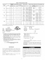
Table 3--ElectdcaJ
UNIT 50ZP
SIZE
036
VOLTAGE
RANGE
V-PH-HZ
MIN
208/230-3-60
042
048
MAX
187
208/230-3-60
187
208/230-3-60
187
208/230-3-60
COMPRESSOR
187
254
RLA
LRA
8.9
254
64.5
10.9
254
Nominal
1.4
414
508
7.4
64
0.7
POINT POWER SUPPLY
FUSE OR
HACR BKR
-/.
3.8/5.0
7.5/10.0
11.3/15.0
15/20
-/10.4/12.0
20.8/24.1
31.3/36.1
41.7/48.1
15.4/15.4
16.5/18.5
29.6/33.8
42.6/48.8
55.6/63.8
-/.
3.8/5.0
7.5/10.0
11.3/15.0
15/20
-/10.4/12.0
20.8/24.1
31.3/36.1
41.7/48.1
17.9/17.9
17.9/18.5
29.6/33.8
42.6/48.8
55.6/63.8
25/25
40/40
50/80
4.2
-/.
3.8/5.0
7.5/10.0
11.3/15.0
15/20
-/10.4/12.0
20.8/24.1
31.3/36.1
41.7/48.1
21.1/21.1
21.1/21.1
31.3/35.3
44.3/50.4
57.4/65.4
30/30
40/40
50/80
5.8
-/.
3.8/5.0
7.5/10.0
11.3/15.0
15.0/20.0
-/10.4/12.0
23.8/24.1
31.3/36.1
47.7/48.1
27.8/27.5
27.5/27.5
33.3/37.3
46.3/52.3
59.3/67.3
35/35
50/50
60/80
5
10
15
20
6
12
18
24
12.8
12.8
18.3
25.8
33.3
20
25
35
40
50
2.6
KW*
SINGLE
MCA
060
460-3-60
HEAT
FLA
2.8
1.5
114
ELECTRIC
2.8
1.5
73
16.3
IFM
FLA
1.5
73
12.3
254
OFM
FLA
Data--50ZP
DISCONNECT
MOCP
25/25
35/25
50/50
60/70
60/70
80/90
25/25
25/28
35/80
45/80
80/70135/35
35/35
35/40
50/80
80/70120
20
20
30
35
FLA
LRA
15/15
15/17
27/31
39/45
51/59
74
17/17
17/17
27/31
39/45
51/59
83
21/21
21/21
28/32
41/46
53/60
87
27/27
27/27
31/34
43/48
55/62
131
15
15
18
24
31
70
71
71
71
71
(See legend following Electrical Data charts)
EXAMPLE: Supply voltage is 460-3-60.
A B C
AB = 452 v
AC = 455 v
FLA
-- Full Load Amps
LRA
-- LockedLEGEND
RotorAmps
C Q
MCA
-- Minimum Circuit Amps
MOCP -- Maximum Overcurrent Protection
RLA
-- Rated Load Amps
CKT BKR -- Circuit Breaker
US
Average Voltage = 452 + 464 + 455
3
BC = 464 v
= 1371
3
= 457
NOTES:
1. In compliance with NEC (National Electrical Code) requirements
for multimotor and combination load equipment (refer to NEC
Articles 430 and 440), the overcurrent protective device for the
unit shall be Power Supply fuse. Canadian units may be
fuse or circuit breaker.
2. Minimum wire size is based on 60 C copper wire. If other than
60 C wire is used, or if length exceeds wire length in table,
determine size from NEC.
3. Unbalanced
3-Phase Supply Voltage
Never operate a motor where a phase imbalance in supply voltage is greater than 2%. Use the following formula to determine
the percentage of voltage imbalance.
Determine maximum deviation from average voltage.
(AB) 457 452=5v
(B0) 464 457=7v
(AC) 457 455=2v
Maximum deviation is 7 v.
Determine percent of voltage imbalance.
7
% Voltage Imbalance = 100 x -457
= 1.53%
This amount of phase imbalance
maximum allowable 2%.
% Voltage imbalance
= 100 x
max volta
e deviation from avera e volta
average voltage
is satisfactory
as it is below the
e
IMPORTANT:
If the supply voltage phase imbalance
is
more than 2%, contact your local electric utility company
immediately.
MAINTENANCE
To ensure
bility
continuing
high perflmnance,
of premature
be perlormed
inspected
on
equipment
failure,
this equipment.
at least once each
troubleshoot
cooling
back of book.
and to reduce
periodic
This
cooling
year by a qualified
of units,
refer
the possi-
maintenance
The
must
ability
unit
should
be
equipment,
service
person.
To
perlimn
to Troubleshooting
chart
to properly
ment requires
in
certain
l[f you do
any maintenance
procedures
TO HEED
The minimum
%llows:
12
maintenance
mechanical
not possess
these,
DEATH
maintenance
OR DAMAGE
requirements
on this equipskills,
tools
and
do not attempt
on this equipment,
recommended
in the User's
THIS WARNING
COULD
OtIS INJURY,
MENT.
NOTE TO EQUIPMENT OWNER: Consult your local dealer
about the availability of a maintenance contract.
perlorm
expertise,
to
other than those
Manuah
RESULT
TO THIS
FAILURE
1N SERIEQUIP-
l_}r this equipment
SIZE
are as
SCHEMATIC
208/230
3 50
Sm _
51ZE
2
AWG
FIELD
u_L_BLK
BLK
I P_- _YEL
LI_
UBEDHEATERWITHoPTIONS
POWER
SUPPLY
MAXIMUM
SIZE
WIRE
2
m_mmm_L<_
L2_
YEL
L3
BLUI
ELECTRIC
°
POINT
_
CONNECTION
i
FF_
USED
BO_
p_
L
OVERLOAD
{03B,
O4B
TDR_
80BO)
ALL
_
,n
_
I
LS__BLU_
I_LU_
"''BLU_
(0_,042
& O_
_
\
_BLK_
_
T
--
__
QTCAP_"-'=_--------GRN
YEL-----1
'
YEL
|
I
I
I,
_
--
_
I
I
I
I
I
I
F- ....
IGRN_BRN--_--
AN,
-RED
F...... =
_RED_BRN_BRN
!
_RED
____ON
.....
/--
_C036,042
_
060)
R
YEL .....
I
WHT
14
I-_-
I
/
/
BRN--
RED I
..............
_
IFM
I
F
4EA_
048
/-
_RED_
__L-BLU
I
I
k_f_J_iN
PROTECTOR
EXCEPT
HEATERS
I_YEL_
MAXIMUM
WIRE
SIZE
210
AWG
....
IIBLU__RED
k
_YEL_
1
OLU
3w V
YEL_'--'_________._
IFR
_
_'"I LLECTR_C"
"J_=_YEL_YELJ_
I
_
_
I
_LK_
HEAT
OPTIONS
QT_
BLU
I
BLK
_O_I_LY.
HEATER
_
_
WITH
ELECTRIC
I
I
OFM
_
I
AWO
• SINGLE
SEE
1
_..i_==#J--L-4-.1 1
I_
CAr_p2YEL
YEL_;BRN_I_
YEL
.,ia----------_LK-4P--k----_I
_
I
--I-,_--,ELI
....
YEL
OPTION
ONLY.
HEAT
BLKI____
--
5UPPLY
ELECTRIC
_
F
BRN
24V
YEL_BRN
_
_
_
IO,OKWANDABOVE
_
_
_
_
24V
_BRN_
_
_
BOX
_R_R,
_
_
SPLICE
3
5PLICE
,ox
_l
COMMON
(SEE
NOTE_2)
BRN_
I
_
I
_
I
_
I
_
I
]
BRN
BRN'
HR1
'BRN
TDRj3
i
OR
IFR;3
LEGEND
24VBS_ICE
COMPONENT
ARRANGEMENT
FIELD
{x)
WIRE
TERMINAL
BLK--{iS)
(ii}
SPLICE
MARKED
YEL
BRN
0
(MARKED)
TERMINAL
COMP
(UNMARKED)
TERMINAL
@
BLOWER
BLOCK
SPLICE
C
CONTACTOR,COMPRESBOR
CAP
CAPACITOR
COMP
COMPRESSOR
EQUIP
EQUIPMENT
FL
FUSE
FU
FUSE
OND
GROUND
HR
HEATER
]FM
MOTOR
LINK
RELAY
INDOOR
FAN
INDOOR
INTERNAL
FAN
(STRIP
HEAT)
MOTOR
HOUSING
SPLICE
(MARKED)
IFR
IP
RELAY
PROTECTOR
GND
_R
INDOOR
.......
L_ _
RN
YELI
BRN
FACTORY
i
=
_
--
FAN
i
E .......
i
FIELD
CONTROL
i
FIELD
_I_
ACCESSORY
HEAT
BRN
TO
_CCESSOR_
WIRING
POWER
WIRING
OR
INDICATE
OPTIONAL
WIRING
COMMON
OUTDOOR
FAN
QT
_UADRUPLE
TERMINAL
BB
SLOW
FUSE
TB
TERMINAL
TDR
TIME
TH
THERMOSTAT
TRAM
TRANSFORMER
BLOW
MOTOR
BLOCK
DELAY
RELAY
HEATING
ONLY,
POTENTIAL
NOT
WIRING
OFM
REPRESENT
TO
WIRING
NOTES
1.IF
ANY
MUST
WITH
2ISEE
............ACCESSORY
ONLYEQuIPGND
__
........
_
'
_@OFM
CAP
AND
_ .....
OF
BE
THE
ORIGINAL
WIRE
REPLACED,IT
MUST
90_C
OR
TYPE
PRICE
PAGES
WIRE
FOR
FURNISHED
BE
ITS
REPLACED
EQUIVALENT.
THERMOSTAT
SUBBASE
FAN
3.5ET
HEAT
ANTICIPATOR
AT
SEQUENCE
FOR
TDR
.6
TDR
0
DISCONNECT
ER
24V
POWER
T
T+30
ENTRY
NEC
A06023
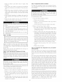
Fig. 16A--Wiring
Diagram 208/230-3-60
13
BLK
CAP2
YEL
YE L_
BRN
OFM
QT /
3LU
COMP
BLK_
gEL
OVERLOAD
PROTECTOR
RED_----'_
c_L_
HEAT SCHEMATIC
YEL
ELECTRIC
QT
HEATERS
IFM
CAP1
--
_I
=RED
THERMOSTAT
I
SUB
BRN--
BASE
R
_AB_
_
_GRN
IGRN_
IcOOL
YEL
i
WHT
H1
_
_T_
i-IH2
I
.......
.....
t
NOTE_21
--
mm_mmmmm_VFT_
_
--
_
--
_
m
....
SEE
IT
BRN
_
HEATER
J
_
J
_
J
TDR
2_
_
I
_!
J
_
_L_BRN
X......
LABEL
CONNECTIONS.
_-
SPLICE
C
_BRN-ACCESSORY
_VI_
--
IO'OKWANDABOVE/
_I
I
_
(SEE
_VIO
I
24V
YEL_BRN"_
_OOL
_OM_
BRN
_BRN_D
J
_BRNJ
HRI
--
BRN--
m
TDR;B
LEGEND
FIELD
SPLICE
C
COMPONENT ARRANGEMENT
MARKED
@
BLK_
YEL
<_D
_
TERMINAL
0
TERMINAL
<_
COMP
@
_
INDOOR
_
FAN
SPLICE
EQUIP
FL
EQUIPMENT
FUSE
LINK
(UNMARKED)
OND
GROUND
HR
HEATER
(MARKED)
ON:
°WER
H°US'N
FACTORY
........
L_i---l
@G
m_
NT
.............
WIRING
FIELD
CONTROL
FIELD
POWER
_m_
ACCESSORY
_
TO
J
._ .B_LU_
i_
/'
TD_
'_1_1
RN YEL--
_1
cCFAMP2cAP
IFC_Pc1Apm_
WITH
--
AND
HEAT
_-
E
INDOOR
IP
INTERNAL
FAN
(STRIP
HEAT)
MOTOR
PROTECTOR
OFM
QT
OUTDOOR
QUADRUPLE
TB
TERMINAL
FAN
MOTOR
TERMINAL
TDR
TIME
TH
THERMOSTAT
TRAN
TRANSFORMER
BLOCK
DELAY
RELAY
OPTIONAL
OR
HEATING
WIRING
COMMON
ONLY:
REPRESENT
WIRING
_l
AOOESSORYONLYr'P'
I
@
@
GND _
RELAY
IFM
WIRING
WIRING
INDICATE
TO
MOTOR
NOTES
| _cLc_EC_s_OIRCy
i
2,5EE
EQUIP
(MARKED)
SPLICE
NOT
S_Gg_
ELECTRIC
COMPRESSOR
BLOCK
POTENTIAL
r
CAPACITOR
COMP
BRN
TERMINAL
,COMPRESSOR
CAP
WIRE
24V#0PxLIC
E
TYPE
90"C
PRICE
PAGES
5UBBASE
WIRE
FOR
PART
OR
ITS
EQUIVALENT.
THERMOSTAT
NUMBERS.
3ISET
HEAT
ANTICIPATOR
4.USE
75_C
COPPER
5,FOR
HIGH
SPEED
AT
,6
CONDUCTORS
ONLY.
FAN
WIRE
FROM
TDRj3
IFM,
D[SCONNECT
AND
CONNECT
WIRE
FROM
SEQUENCE
FOR
TDR
BLU
BLK
TDR
(1,3)
'l
o
24V POWER ENTRY
AND
CONNECT
ORN
[FM.
G
ENERGIZED
DE
i
i
T
T+30
G
ENERGIZED
A06024
Fig. 16B--Wiring
Diagram 460-3-60
14
75E
110
88E
258
OUTDOOR
TEMP
oF
oO
OUTDOORTEMP
_F
_C
100
I
I
115
105
46
41
_
95
35
75
24
_,
II
110
58B
1 O0
-'_ "]_
2821
-'_
115
46
105
41
95
35
55
45
13
7
->
90
80
%
u_
48:_70
_"
_483
f
_"
45
7
W
f
41_
_60
,Z
z
w
z414
z60
o_
g
D
u750
27E
,,1_ _I
I
I/
_70
mSO
40
278
40
3O
30
30
I
40
SUCTION
I
4
50
LINE
I
10
50
70
TEMPERATURE (°F)
I
I
15
21
SUCTION
LINE
TEMPERATURE
80
90
30
I
27
I
32
I
('C]
40
SUCTION
I
4
SO
LINE
I
I0
50
TEMPERATURE
I
15
70
(°F)
I
21
SUCTION L]NE
TEMPERATURE
("C]
80
90
I
27
I
32
C00017
Fig. 17--Cooling
58E
100
75E
110
Charging
C00019
Chart, 50ZP036 Units
Fig. 19--Cooling
OUTDOORTEMP
_F
_6
HH
"_"
_"
'_
_
_'
_,
_'
_
_,
_'
,,_
'_'
115
105
46
41
95
35
85
29
75
65
24
18
55
13
45
7
258
II0
589
] O0
--_
_821
u3
Charging
Chart, 50ZP048 Units
OUTOOORTEMP
oF
oc
125
52
_.
90
_'
_
,,,
t
t
'
105
115
95
41
46
35
75
24
65
18
_
o
EgO
_'
u_
_"
_
"
C,
_"
.,
g
,#
34E
-"
g
_.'r_
i
mSO
U_so
4_ 7
i
i
i
_
m
27E
40
278
30
40
3O
3O
40
50
50
70
SUCTION LINE TEMPERATURE (°F)
I
I
I
I
4
10
15
21
SUCTION LINE TEMPERATURE ('C]
80
I
27
90
30
I
32
I
40
SO
C00018
Fig. 18--Cooling
Charging
50
SUCTION LINE TEMPERATURE
I
I
I
4
10
15
SUCTION L]NE TEMPERATURE
70
80
90
(°F)
I
21
("C]
I
27
I
32
C00020
Chart, 50ZP042 Units
Fig. 20--Cooling
15
Charging
Chart, 50ZP060 Units
1. Inspect air filter(s)
necessary.
each month.
Clean
or replace
Step 3--Evaporator
when
and Motor
For longer lili:, operating economy, and continuing efficiency,
clean accunmlated dirt and grease li"om the blower wheel and
motor annually.
2. Inspect indoor coil, outdoor coil, drain pan, and condensate
drain each cooling season lbr cleanliness. Clean when necessary.
3. Inspect blower motor and wheel lor cleanliness each cooling
season. Clean when necessary. For first heating season,
inspect blower wheel bimonthly to determine proper cleaning
b'equency.
Disconnect and tag electrical power to the unit belk_re
cleaning the blower wheel. Faihn'e to adhere to this warning
could cause serious injury or death.
4. Check electrical connections lbr tightness and controls l_r
proper operation each cooling season. Service when necessal-y.
5. Check the drain channel in the top cover periodically
blockage (leaves, insects). Clean as needed.
Blower
To clean the blower wheel:
1. Access the blower assembly as lbllows:
lbr
a. Remove top access panel.
b. Remove 3 screws that hold blower orilice ring to blower
housing. Save screws.
Failure to lbllow these warnings could result in serious injury
or death:
c. Loosen setscrew(s) which secure wheel to motor sbalk.
2. Remove and clean blower wheel as lbllows:
1. Turn olT electrical power to the unit belore perlorming any
maintenance or service on the unit.
a. Lilt wheel li"om housing. When handling and/or cleaning
blower wheel be sure not to disturb balance weights (clips)
on blower wheel vanes.
2. Use extreme caution when removing panels and parts. As
with any mechanical equipment, personal injuU can result
li"om sharp edges, etc.
3. Never place anything combustible either on, or in contact
with_ the unit.
Step 1--Air
b. Remove caked-on dirt from wheel and housing with a
brush. Remove lint and/or dirt accumulations li"om wheel
and housing with vacuum cleaner, using a solk brush
attachment. Remove grease and oil with a mild solvent.
Filter
Never operate the unit without
return-air duct system. Always
same dfinensional size and type
Table 1 lk_rrecommended filter
c. Reassemble blower into housing. Place tapper orifice ring
on blower to judge location of the blower wheel. Blower
wheel should be approximately 0.2-in. below bottom ol'
orifice ring when centered correctly. Be stare setscrews are
tightened on motor and are not on round part of shali.
a suitable air filter in the
replace the filter with the
as originally installed. See
sizes.
d. Set tapper orifice ring in place with 3 screws removed in
step 1.
Inspect air filter(s) at least once each month and replace
(throwaway-type) or clean (cleanable-type) at least twice during
each cooling season or whenever the filters become clogged with
dust and lint.
Replace filters with the same dimensional
originally provide& when necessary.
Step 2--Unit
e. Replace top access paneh
Step 4--Condenser
sate Drain Pan
size and type as
Top Removal (Condeneer-Coil
Coil, Evaporator Coil, and Conden-
Inspect the condenser coil, evaporator coil, and condensate drain
pan at least once each year. Proper inspection and cleaning
requires the removal of the unit top. See Unit Top Removal section
Side)
NOTE: When perlorming maintenance or service procedures that
require removal of the unit top, be sure to perli)rln all of the routine
maintenance procedures that require top removal, including coil
inspection and cleaning, and condensate drain pan inspection and
cleaning.
ahoy('.
1. Remove 7 screws on unit top cover surface. (Save all screws.)
The coils are easily cleaned when dry; therelbre, inspect and clean
the coils either belore or alter each cooling season. Remove all
obstructions (including weeds and shrubs) that interli.:rc with the
airflow through the condenser coil. Straighten bent fins with a fin
comb. If coated with dirt or lint, clean the coils with a vacuum
cleaner, using a sol1 blq.lsh attachment. Be careful not to bend the
fins. If coated with oil or grease, clean the coils with a mild
detergent-and-water-solution.
Rinse coils with clear water, using a
garden hose. Be careful not to splash water on motors, insulatiom
wiring or air lilter(s). For best results, spray condenser-coil fins
from inside to outside the unit. On units with an outer and inner
condenser coil be stare to clean between the coils. Be sure to flush
all dirt and debris from the unit base.
2. Remove 2 screws on unit top cover flange. (Save all screws.)
Inspect
3. Lil_ top b'om unit carefully. Set top on edge and make stare
that top is supported by unit side that is opposite duct (or
plenum) side.
the coils. Clean the drain pan and condensate
Disconnect and tag electrical power to the unit belbre
removing top. Failure to adhere to this warning could cause
serious injury or death.
Only qualified service personnel should perlorm maintenance and
service procedures that require unit top removah
Relier to the lollowing top removal procedures:
the drain pan and condensate
lk_reign matter
clear
or
4. Carefully replace and secure unit top to unit, using screws
removed in steps 1 and 2, when maintenance andk_r service
procedures ale completed.
water. Do not splash
air filter(s),
"phnnbers
auxiliary
16
li"om the pan.
If the
snake"
drain
port above
similar
tube
the pan and drain
is restricted,
probe
the drain
inspecting
drain by removing
water on the insulation,
drain
or
Flush
drain line when
device.
tube
all
with
motor_ wiring,
clear
it with
Ensure
that
robe is also clear.
a
the
Table 4--Dry
(Deduct
Coil Air Delivery* Horizontal Discharge
10 percent for 208 Volt Operation)
230 AND 460 VOLT
Unit
Motor Speed
Low
Med
036
High
Low
042
Med
High
Low
048
Med
Low
O6Ot
2 Speed
Med
High
Low
060
Med
3 Speed
High
Table 5--Wet
UNIT SIZE
5OZP
0.1
0.2
0.3
0.7
0.8
Watts
480
435
420
400
380
338
326
311
Cfm
1231
1218
1204
1120
1008
950
863
751
Watts
470
480
445
410
388
359
338
321
Cfm
1302
1264
1205
1163
1081
940
873
783
Watts
660
635
610
875
540
505
485
460
Cfm
1700
1660
1581
1450
1297
1190
1095
999
Watts
478
488
440
411
378
350
327
317
Cfm
1303
1270
1224
1179
1126
1022
911
816
Watts
481
468
480
438
404
370
338
320
Cfm
1310
1280
1241
1181
1110
1022
943
811
798
678
647
618
578
540
500
Cfm
1736
1688
1618
1510
1421
1309
1187
Watts
801
760
730
688
650
600
570
Cfm
1898
1841
1757
1682
1564
1429
1365
Watts
870
842
818
782
696
632
628
Cfm
2000
1903
1799
1718
1625
1446
1333
Watts
890
880
810
790
735
680
580
480
422
Cfm
1834
1820
1791
1762
1703
1640
1415
1159
950
Watts
1040
1018
1000
950
890
835
790
650
58O
Cfm
2230
2102
2025
1960
1901
1855
1752
1468
1121
Watts
1073
1038
1001
958
896
840
800
691
575
Cfm
2230
2202
2160
2122
2052
1926
1791
1588
1202
Watts
1058
1008
942
891
860
828
750
700
630
Cfm
2384
2200
2197
2071
1989
1889
1820
1729
1640
Watts
1266
1086
1021
1002
977
924
860
819
700
Cfm
2724
2476
2392
2344
2262
2132
2001
1910
1820
Watts
1301
1216
1197
1127
1058
1011
979
869
870
Cfm
2760
2618
2543
2423
2292
2169
2056
1943
1832
Coil Pressure Drop
PRESSURE
Table 6--Filter
DROP
FILTER
SIZE
(IN.)
500
600
700
800
900
1000
1100
1200
1300 J1400
036-042
24 x 24
0.06
0.07
0.08
0.08
0.09
0.09
0.09
0.10
0.11
0.12
1200
0.09
048,060
24 x 30
0.08
0.09
1400
0.11
1600
0.12
1000
0.04
1200
0.06
UNIT
SIZE
5OZP
FILTER
SIZE
(IN.)
1500
1600
1400
0.08
036-042
24 x 24
0.14
0.15
1600
0.09
048,060
24 x 30
0.10
0.11
1400
0.07
1600
0.08
1800
0.09
1700
0.07
060
1800
0.08
2100
0.09
2300
0.10
CFM
CFM
Table 7--Accessory
HEATER5.20
KW_600
1900
2000
2100
2200
2300
0.12
0.13
0.14
0.15
0.16
0.17
0.18
Electric Heat Pressure
(in. wg)
Drop
800
1000
1200
1400
1600
1800
2000
22000.25
Fan
fan free
operation.
li"om all obstructions
condenser-fan
Never
place
articles
assembly
screws
(grille,
and flipping
top cover.
to ensure
on top of the
to unit may result.
1. Shut off' unit power
1800
CFM
and fan) by removing
cooling
1700
I
2. Remove
unit. Damage
Pressure Drop (in. wg)
UNIT
SIZE
50ZP
048
proper
1060
(IN. WG)
0.07
042
the condenser
735
(CFM)
1000
036
Keep
0.9
Watts
AIRFLOW
Step 5--Condenser
External Static Pressure (in. wg)
0.4
0.5
0.6
Air Delivery
supply.
3. Loosen
fan hub setscrews.
4. Adjust
fan height
5. Tighten
17
setscrews.
as shown
in Fig. 21.
motor,
motor
assembly
cover,
onto unit
6. Replace
condenser-fan
assembly.
Step 6--Electrical
Controls
Step 7--Refrigerant
Circuit
Inspect all refrigerant tubing connections and the unit base Iiw oil
accumulations annually. Detecting oil generally indicates a refi'igerant leak.
and Wiring
Inspect and check the electrical controls and wiring annually. Be
.sur(, to furlz (_'tlle electrical power to the unit.
If oil is detected or if low cooling perli_rmance is suspected,
leak-test all refi"igerant robing using an electronic leak-detector, or
liquid-soap solution. Ira reli"igerant leak is detected, relier to Check
fiw Refi"igerant Leaks section. (See Table of Contents li)r page
nun'_ber.)
Remove the top panel to locate all the electrical controls and
wiring. Check all electrical connections lor tightness. Tighten all
screw connections. If any smoky or burned connections are
noticed, disassemble the connectiom clean all the parts, restrip the
wire end and reassemble the connection properly and securely.
If no refrigerant leaks are limnd and low cooling perfkwmance is
suspected, reli:r to Reli"igerant Charge. (See Table of Contents lor
page nnmber.)
3.125 in.
Step 8--Evaporator
The cooling airflow does not require checking unless in,proper
perlkwmance is suspected. !_J"u problem ('xL_t_, be m_r(, that cHl
SUl_plv-cmd returll-_tir grille,s are ol)ell ut_d_)'('e.f}'omol)structiot*,s,
und theft the c_ir,_i'lter is clecm. When necessary, reler to Indoor
Airflow and AirlIow Adjustments section to check the system
airflow. (See Table of Contents fkw page number.)
C00021
Fig. 21--Condenser-Fan
Airflow
Adjustment
After inspecting the electrical controls and wiring, replace all the
panels. Start the unit, and observe at least one complete cooling
cycle to ensure proper operation. If discrepancies are observed in
operating cycle, or iX'a suspected malfunction has occurred, check
each electrical component with the proper electrical instrnmentation. Reli:r to the unit wiring label when making these checkouts.
Step 9--1Vletering
Devices
Rel)'igerant metering devices are fixed orifices and are located in
the inlet header to the evaporator coil.
Step lO--Liquid
Line Strainer
The liquid line strainer (to protect metering device) is made of wire
mesh and is located in the liquid line on the inlet side of the
metering device.
NOTE: Reli:r to the Sequence of Operation section as an aid in
deterndning proper control operation. (See Table of Contents Iiw
page number. )
18
TabJe 8--TroubJeshooting--CooJing
CAUSE
REMEDY
Power Failure
Call power company
SYMPTOM
Fuse blown or circuit breaker tripped
Defective thermostat, contractor,
control relay
Compressor
and condenser
fan will not start.
Insufficient
Incorrect
transformer,
Compressor
will
not
start
runs.
but
condenser
Lower thermostat
in compressor
motor burned out, seized, or internal
overload open
fan
Defective run/start capacitor,
One leg of 3-phase
Refrigerant
overcharge
overload,
start relay
or undercharge
cycles
(other than normally
satisfying
thermostat).
Defective
run/start capacitor, overload or start
relay
Defective thermostat
Faulty condenser-fan
Restriction
operates
charge
pressure.
air restricted
too low.
Compressor
Restriction
suction
pressure.
Compressor
Refrigerant
Suction
pressure
too low.
or air short-cycling
charge
19
Determine
cause and correct
and re-
Remove restriction
valves leaking
Replace compressor
overcharged
Recover excess
refrigerant
Replace Filter
charge
filter-drier
evacuate system,
charge
Check for source and eliminate
restricted
Check for leaks, repair, and recharge
Remove source of restriction
Increase air quantity
Check filter- replace if necessary
airflow
Temperature too low in conditioned
Outdoor ambient below 40°F
Field-installed
refrigerant
Recover refrigerant
Replace compressor
in liquid tube
evaporator
and re-
Check for leaks, repair and recharge
device or low side restricted
Insufficient
evacuate system,
charge
Clean coil
valves leaking
Low refrigerant
unit size
repair, and recharge
Recover excess
Dirty air filter
Metering
Replace filter
load or increase
Replace filter
High heat load
Excessive
Replace
coil
overcharged
Low refrigerant
Head pressure
Replace thermostat
Clean coil or remove restriction
Air in system
Condenser
cause and replace
Recover refrigerant,
coil dirty or restricted
Dirty condenser
head
Determine
Replace compressor
Dirty air filter
Excessive
cause and correct
Locate leak
Air in system
Refrigerant
Determine
Reset thermostat
Leaking valves in compressor
Condenser
cause and replace
Recover refrigerant, evacuate system, and recharge to capacities shown on nameplate
Decrease
set too low
Low refrigerant
continuously.
Determine
Locate restriction and remove
system
Dirty air filter
Unit undersized for load
Compressor
Determine cause
Replace compressor
motor or capacitor
in refrigerant
Thermostat
Check wiring and repair or replace
Replace and determine cause
Determine cause and correct
line voltage
Blocked condenser
Compressor
setting below room temperature
Replace fuse or reset circuit breaker
Determine cause
power dead
Defective compressor
Insufficient
cause and correct
Check wiring diagram and rewire correctly
setting too high
Faulty wiring or loose connections
circuit
Replace component
Determine
line voltage
or faulty wiring
Thermostat
Compressor
Replace fuse or reset circuit breaker
or
area
Reset thermostat
Install low-ambient
Replace
kit
START-UP
CHECKLIST
(REMOVE AND STORE IN JOB FILE)
I. PRELiMiNARY
iNFORMATiON
Model No .............................................................................................................................................................
Serial No ..............................................................................................................................................................
Date ......................................................................................................................................................................
Technician
...........................................................................................................................................................
II, PRE-START-UP
Verify that all packing materials have been removed from unit
Verify that condensate
connection
is installed per installation
instructions
Check all electrical connections and terminals for tightness
Check that indoor (evaporator) air filter is clean and in place
Verify that unit installation is level
__
ill, START-UP
Check fan wheel propeller for location in housing and setscrew tightness
Supply Voltage: L1-L2 _
L2-L3
Compressor
L2
Amps: L1
Indoor (Evaporator)
TEMPERATURE
Fan Amps:
Outdoor (Condenser)
Return-Air
L3-L1
L3
Air Temperature:
Temperature:
Cooling Supply Air:
PRESSURES
Refrigerant
Suction
Refrigerant
Discharge
_
DB
DB
WB
DB
WB
psig
Suction Line Temp*
psig
Discharge Temp?
Verify Refrigerant
charge using charging tables
Verify that 3-phase scroll compressor
*Measured
(50GL030-060)
is rotating in correct direction.
at suction inlet to compressor
?Measured at liquid line leaving condenser
Copyright
2006 CARRIER
Manufacturer
B°°kLL__
Tab 16al 8a
reserves
PC 101
Corp. * 7310 W. Morris St. • Indianapolis,
the right
to discontinue,
Printed in U.S.A.
IN 46231
or change at any time, specifications
Catalog
No. 50ZP-5SI
or designs
without
notice
Pg 20
and without incurring
2-06
obligations.
Replaces:
New