1
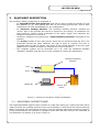
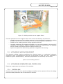
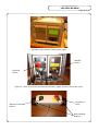
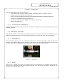
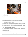
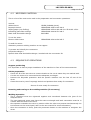
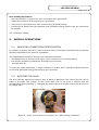
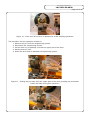
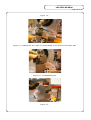
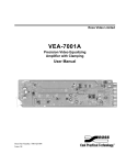
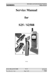
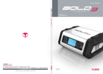
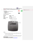
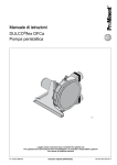
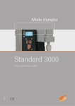
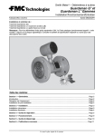
CERN
LHC Project Document No.
LHC-DFB-ES-0020
CH-1211 Geneva 23
Switzerland
CERN Div./Group or Supplier/Contractor Document No.
AT-ACR/IC
the
EDMS Document No.
Large
Hadron
Collider
497441
project
Date: 2004-12-10
Engineering Specification
ULTRASONIC WELDING OF SPOOL PIECE
AND LATTICE CORRECTOR CABLES IN THE
DFB INTERCONNECTIONS
Abstract
The auxiliary bus bars are used to power the auxiliary superconducting magnets of the
LHC machine. The ultrasonic welding technique was chosen to perform some 3000
connections taking place in the cryogenic Feed Boxes (DFB). This Functional
Specification explains how to use the ultrasonic welding machine to splice two types of
wires (type Spool Piece and type Lattice Corrector) used in the DFB.
Prepared by :
To be Checked by :
To be Approved by :
Redwane MARIE
AT-ACR/IC
[email protected]
A. JACQUEMOD
A.PERIN
R. VAN WEELDEREN
L. TAVIAN
LHC Project Document No.
LHC-DFB-ES-0020
Page 2 of 16
History of Changes
Rev. No.
0.1
Date
Pages
Description of Changes
1st draft prepared by R. MARIE on the basis of LHC-QBBI-ES0001.00 v1.0 by A. JACQUEMOD and I. MONTEIRO.
LHC Project Document No.
LHC-DFB-ES-0020
Page 3 of 16
Table of Contents
1.INTRODUCTION........................................................................................... 4
2.SCOPE OF THIS DOCUMENT..........................................................................4
2.1TYPES OF CABLES.........................................................................................4
2.2TYPES OF WIRES.......................................................................................... 4
2.3CABLE LOOPS.............................................................................................. 4
2.4LOCATION OF THE CONNECTIONS.................................................................. 5
2.5RELATED SPECIFICATIONS............................................................................ 5
2.6CHOICE OF THE TECHNOLOGY....................................................................... 5
3.EQUIPMENT DESCRIPTION.......................................................................... 6
3.1ADJUSTABLE SUPPORT FRAME....................................................................... 6
3.2ULTRASONIC WELDING EQUIPMENT............................................................... 7
3.3ULTRASOUND GENERATOR AND CONTROL BOX ............................................... 7
3.3.1CONTROL BOX...................................................................................................... 7
3.3.2ULTRASOUND GENERATOR..................................................................................... 9
3.4SPECIFIC TOOLING....................................................................................... 9
3.4.1SONOTRODE......................................................................................................... 9
3.4.2ANVIL.................................................................................................................. 9
3.4.3SUPPORT............................................................................................................ 10
3.4.4OTHER TOOLING.................................................................................................. 10
4.CONNECTION OF TWO WIRES....................................................................10
4.1REQUIRED PERSONNEL AND SKILLS..............................................................10
4.2NECESSARY MATERIAL................................................................................ 11
4.3SEQUENCE OF OPERATIONS......................................................................... 11
5.SPECIAL OPERATIONS............................................................................... 12
5.1WIRES AND CONNECTION IDENTIFICATION................................................... 12
5.2ROTATING THE ANVIL................................................................................. 12
5.3USING THE SOFTWARE MECAWIN 5.3........................................................... 15
5.4REPAIRING A CONNECTION..........................................................................15
5.5POSITIONING THE ANVIL............................................................................. 15
5.6CHANGING THE WELDING PARAMETERS........................................................ 15
6.REFERENCE DOCUMENTS............................................................................16
LHC Project Document No.
LHC-DFB-ES-0020
Page 4 of 16
1.
INTRODUCTION
The auxiliary bus bars are used to power the auxiliary superconducting magnets of the LHC
machine with nominal electrical currents up to 600A. The chosen jointing method is ultrasonic
welding. Some 3000 welds will have to be made in the DFB. This Functional Specification gives
the requirements and specifications for the ultrasonic welding machines, which will be of two
types (type spool-piece and type Lattice Corrector).
2.
SCOPE OF THIS DOCUMENT
2.1
TYPES OF CABLES
This Engineering Specification deals with the electrical connections of the Lattice Corrector
cables (2 mm2 wires) and the Spool Piece cables (3 mm2 wires) present in the Cryogenic Feed
Boxes (DFB). The types of bus bars concerned are :
Cable code
Description
DCAD
42 wire-cable for Lattice Corrector Circuits (2 mm²)
DCED
48 wire-cable for Lattice Corrector Circuits (2 mm²)
DCFD
4 wire-cable for Lattice Corrector Circuits (2 mm²)
DCGD
4 wire-cable for Spool Piece Corrector Circuits (3 mm²)
DCHD
22 wire-cable for Spool Piece Corrector Circuits (3 mm²)
DCID
14 wire-cable for Lattice Corrector Circuits (2 mm²)
2.2
TYPES OF WIRES
Two types of 120/600A superconducting wires are present in the DFB:
• the Lattice Corrector Cable (LCC) wire which is circular with a 1.6mm diameter;
•
the Spool Piece Cable (SPC) wire which is circular with a 2mm diameter.
Ø1.6 mm
Ø2 mm
Figure 1: section views of the two types of wires
2.3
CABLE LOOPS
Though the welding operations sequence is identical, this document does not deal with the
making of cable loops for test purposes. For more information, refer to the document LHC-DFBES-xxxx [].
LHC Project Document No.
LHC-DFB-ES-0020
Page 5 of 16
2.4
LOCATION OF THE CONNECTIONS
The concerned interconnections take place inside the DFBA, DFBL and DFBM []. They also
appear between the DFBL or DFBM and the stand alone magnets.
This document does not explain the jointing method for the connection of these cables to the
current leads interface (“pigtail”).
2.5
RELATED SPECIFICATIONS
All the specifications concerning the positions of cables extremities are exposed in the
Engineering Specification LHC-LI-ES-000x [].
2.6
CHOICE OF THE TECHNOLOGY
On the basis of the LHC requirements and the study of various techniques, the AT-CRI group
has chosen the ultrasonic welding for the LHC cryomagnet auxiliary bus bars connection. Its
principle is explained in [1].
The bus bar types available in the DFB are similar to the ones in the cryomagnets and this
soldering technique complies with the DFB environmental constraints [2]. Consequently, it was
decided to use this technique by adapting it to the DFB requirements.
LHC Project Document No.
LHC-DFB-ES-0020
Page 6 of 16
3.
EQUIPMENT DESCRIPTION
The ultrasonic welding equipment is composed of :
– An adjustable frame with positioner that will be used to modify the height (Z) and
the position (X, Y). This system will rest on the tunnel ground and, due to floor
imperfections it must be adaptable for any configuration.
– An ultrasonic welding machine. The ultrasonic welding machine contains the
“active” part of the process and carries a support for the tooling. It transforms the
high frequency electric signal generated by the power supply and transmits the
ultrasonic movement to the tools.
– Ultrasonic vibrations are produced by a high frequency generator connected to the
machine.
– The tooling consists of two main pieces, which are the sonotrode and the anvil. The
sonotrode remains the same whatever the type of wires to connect. The anvil is
equipped with two sets of clamps. The choice of the clamps depends on the wire type
(Spool Piece or Lattice Corrector) to maintain the wires in position.
– The complete system will be controlled via a PC, with the dedicated software
“Mecawin” installed, that will act as a user interface to control the parameters.
Ultrasonic Welding
Machine
Horn
Anvil
Laptop PC
Control and
Power
Figure 2 : Scheme of ultrasonic welding installation
3.1
ADJUSTABLE SUPPORT FRAME
The height adjustable support frame consists of a rigid part resting on a rolling cart that will be
used to position the welding machine to the correct position to weld the N line superconducting
cables. It must be rigid and robust enough to carry the welding machine as well as to protect it
during manipulations. An example of a support frame that has been used for the assembly of
LHC prototype cell (String 2) is given in figure X.
LHC Project Document No.
LHC-DFB-ES-0020
Page 7 of 16
Figure 3 : Welding machine on its support frame
The main parameters of the support frame must ensure the following requirements:
– possible movements of the welding machine in three dimensions to adjust the welding
positions and to remove the machine for the bus bars preparation operations;
– stability of the welding machine during operations insured;
– Complete equipment as compact as possible so as to permit passage in the tunnel. If
necessary, the ultrasonic welding equipment should be removed from the passage
after an official requirement two hours before removing it;
– System to tighten the cables during operation integrated in the tooling.
3.2
ULTRASONIC WELDING EQUIPMENT
The ultrasonic welding machine transforms the electrical power in a mechanical ultrasonic
movement, which is transmitted by the horn to the pieces to weld. The “box” integrates a
transducer (power transformation), a booster (amplification of movement) and the horn.
picture of the welding machine
3.3
ULTRASOUND GENERATOR AND CONTROL BOX
These two components are the heart of the machine.
3.3.1
CONTROL BOX
The aim of the control box is to provide a dialogue interface to the operator. All the US welding
process related parameters will be controlled via this box.
LHC Project Document No.
LHC-DFB-ES-0020
Page 8 of 16
Figure 4 : Front view of the ultrasound
generator (left) and the control box (right)
ON/OFF
switch
Powering
switch
Figure 5 : Back view of the ultrasound generator (right) and the control box (left)
Starting machine
Button
Emergency
Stop
Start Welding
Buttons
LHC Project Document No.
LHC-DFB-ES-0020
Page 9 of 16
Figure 6 : Control Pad
The main functions of the control box are:
– link between all elements: US generator, welding machine, operator control;
– dialogue between operator and machine;
– check of welding machine positions and related parameters to permit operation;
– measure of dissipated energy and drive in;
– LCD screen that allows to display each chosen parameter;
– Shocks protected box.
3.3.2
ULTRASOUND GENERATOR
The Ultrasound generator will provide the ultrasonic vibrations with the required power to the
welding machine.
3.4
SPECIFIC TOOLING
The specific tooling in the ultrasonic welding machine concerns parts which are adapted to the
DFB connections purpose. This includes the sonotrode, the anvil and their moving support.
3.4.1
SONOTRODE
The sonotrode, aka horn is the interface between the vibration generator and the wires to
connect. To properly transmit the vibration to the wires, the sonotrode has special prints on its
contact keys. The dimensions of these prints give the welded zone dimensions.
Figure 7 : Sonotrode
3.4.2
ANVIL
The anvil is a metal piece with a the same print as the sonotrode. It supports and fixes the
wires to be connected during the welding process. The anvil has the same prints as the
sonotrode to maintain the fix wire.
LHC Project Document No.
LHC-DFB-ES-0020
Page 10 of 16
Figure 8 Sonotrode and anvil of the ultrasonic welding machine in DFB configuration
3.4.3
SUPPORT
It is a heavy steel piece linked to the anvil and made to absorb vibrations and position the
system in front of the wires to connect. It includes a manual displacement system with a
graduation respecting the 7 mm-pitch between each set of wires to connect.
3.4.4
OTHER TOOLING
The machine is carried by a mobile lifting table allowing an easy positioning. This table is
equipped with various fittings to hang the cables or carry a bottle of compressed air.
4.
CONNECTION OF TWO WIRES
This paragraph shortly describes the sequence of operations to weld two wires with the
ultrasonic welding machine.
For more details concerning the use of this machine, refer to the user manual [].
For more details concerning the cables and wires positioning and preparation in a specific
interconnection, refer to the corresponding Engineering Specification.
4.1
REQUIRED PERSONNEL AND SKILLS
The connection of the DFB superconducting wires requires 2 technicians. Their skills should
include the following:
• electrical techniques
•
welding/soldering skills
•
use of high-power systems
•
safety rules linked to these fields
One more person is required as a responsible person and quality assurance manager.
LHC Project Document No.
LHC-DFB-ES-0020
Page 11 of 16
4.2
NECESSARY MATERIAL
This is a list of the main tools used in the preparation and connection operations.
Various:
White Gloves
Isopropil Alcohol
Wiping paper (non fluffing)
Insulating glass-fiber tubings
Black heat shrinkable tubings
CELES (SHOWA gloves)
CERN EDMS #58.04.45.300.8
CERN EDMS #55.60.82.168.2 or 55.60.82.152.0
CERN EDMS #04.86.51.208.3
RAYCHEM
To cut the wires:
Electric Cable Cutter
CERN EDMS #34.94.20.205.3
To weld the wires:
Ultrasonic pressure welding machine on its support
To protect and identify the connection:
polyimide tubings Ø
Special white heat shrinkable tubings Ø marked with the connection ID
4.3
SEQUENCE OF OPERATIONS
Support positioning
It is important to have a proper installation of the machine in front of the interconnection.
Cables preparation
• Check the ID of the two wires to connect thanks to the circuit name they are marked with.
•
Cut the two wires to be connected at the adequate overlength.
•
Remove the Polyimide protection with the specific machine over the last 15 mm of the
wires.
Clean the wires by use of isopropyl alcohol and position them ready for connection.
•
Picture of wires ready for connection
Powering and turning on the welding machine (if necessary)
Welding Operation
• The 2 identified wires are tightened together and introduced between the jaws of the
adequate anvil.
• The two positioned wires must have the same overlength and both extremities must be in
contact with the butee of the anvil.
• One operator maintains the wires in position while the other one presses simultaneously the
two buttons on the control pad (refer to the user manual for more information).
• Once the connection is done, push the pneumatic button on the machine to untighten the
wires.
LHC Project Document No.
LHC-DFB-ES-0020
Page 12 of 16
Post-welding Operations
• Move the machine in front of the next connection to be performed.
•
Clean the connection following the given procedure.
•
Surround the connected wires with a 20mm long-polyimide tubing.
•
Protect the PI tubing with the specified heat shrinkable tubing marked with the connection
ID number.
The connection is done.
5.
SPECIAL OPERATIONS
5.1
WIRES AND CONNECTION IDENTIFICATION
For matters of Quality Assurance, each connection has to be properly identified and the splicing
operation data have to be stored in a database.
This identification consists in having cross-references between:
• the identification of the two wires (type, circuit, location of the interconnection)
•
•
the welding operations parameters recorded by the machine
the operators ID
To cross-link these parameters, a single reference is written with a specially dedicated printer
on the heat-shrinkable tubing that protects the connection.
5.2
ROTATING THE ANVIL
The anvil has two tightening systems. Each of them is adapted to one cable type that can be
found in the DFB: LCC 1.6mm, or SPC 2mm. Each side of the anvil is marked with the
corresponding cable diameter (). Changing the cable type to be welded means the anvil has to
be rotated 180°.
Figure 9 : Front view of the anvil in position for a SPC welding operations
LHC Project Document No.
LHC-DFB-ES-0020
Page 13 of 16
Figure 10 : Front view of the anvil in position for a SPC welding operations
The procedure for this operation consists in:
1. Remove the pin from the untightening system
2. Disconnect the untightening system
3. Use an Allen key to partially unscrew the upper part of the anvil
4. Rotate the anvil 180°
5. Screw the anvil and re-assemble the tightening system.
Figure 11 : Pulling the pin away from the upper part of the anvil (pushing the pneumatic
button will help during this operation)
LHC Project Document No.
LHC-DFB-ES-0020
Page 14 of 16
Figure 12 :
Figure 13 : rotating the anvil 180°. It should adapt in the groove of the lower part.
Figure 14 : re-assembling the
Figure 15 :
LHC Project Document No.
LHC-DFB-ES-0020
Page 15 of 16
5.3
USING THE SOFTWARE MECAWIN 5.3
The normal use of the welding machine does not require an external software. Though it only
keeps in memory data concerning the last operation. The Mecawin software enables to store all
the data needed to identify and check the quality of the connections.
Due to the required quality level for the LHC assembly, all data concerning each weld and the
machine parameters should be recorded. Consequently, during all work and test operations,
the control box is linked to a computer through a RS-232 port. The dedicated software
“MECAWIN” enables to bypass the control box and fully control the welding parameters.
5.4
REPAIRING A CONNECTION
In some conditions, the quality of a connection may be in doubt. A weld made with ultrasound
pressure cannot be repaired. The procedure consists in cutting the connection and making a
new one between the same wires.
1.
2.
3.
4.
5.
6.
Identify the corresponding connection
Disassemble the connection boards to access the connection
Bend the connected wires ready for the connection operation (perpendicular to the board)
Remove the protection around the connection
Cut both wires 2mm before the welded lengths (marked with prints)
Perform a new connection (Chapitre 4)
5.5
POSITIONING THE ANVIL
This operation needs to be done only when the anvil is disconnected from its support for
reasons of maintenance for example. This happens only at the first installation of the anvil on
this support.
This operation should in no circumstance be performed during the normal operations. If
needed, please refer to the responsible person and the manual of the welding system.
5.6
CHANGING THE WELDING PARAMETERS
The welding parameters are recorded in the control box for each cable type. They are locked by
the responsible person, certified by quality tests and should not be modified. Please refer to
the manual of the welding machine for more information.
LHC Project Document No.
LHC-DFB-ES-0020
Page 16 of 16
6.
REFERENCE DOCUMENTS
Reference Number
LHC-LI-ES-0001
LHC-DFB-ES-0012
LHC-DFB-ES-0004
SM 4.0 01.28
EDMS No. (if any)
90001
-
Title
Arc cryomagnet extremities
DFB Electrical Connections
User Manual for the CERN ultrasonic
welding machine
Cable loops