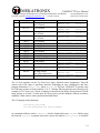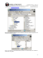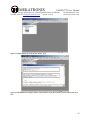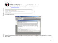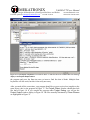
1
TALRIK-IV Users Manual
by
Keith L. Doty
Copyright © 2005 by Mekatronix™.
Version 01
MEKATRONIX
TALRIK-IV™Users Manual
Design & Manufacture of Intelligent Machines and Robots
Technical questions [email protected]
316 NW 17 Street
www.mekatronix.com
Gainesville Florida 32603
AGREEMENT
This is a legal agreement between you, the end user, and MEKATRONIX™. If you do not agree
to the terms of this Agreement, please promptly return the purchased product for a full refund.
1. Copyright Notice. MEKATRONIX™ hereby grants to any individuals or organizations
permission to reproduce and distribute copies of this document, in whole or in part, for any
personal or non-commercial educational use only. This copyright notice must accompany
any copy that is distributed.
2. Copy Restrictions. Other than cases mentioned in Copyright Notice, no part of any
MEKATRONIX™ document may be reproduced in any form without written permission of
MEKATRONIX™. For example, MEKATRONIX™ does not grant the right to make
derivative works based on these documents without written consent.
3. Software License. MEKATRONIX™ software is licensed and not sold. Software
documentation is licensed to you by MEKATRONIX™, the licensor and a corporation under
the laws of Florida. MEKATRONIX™ does not assume and shall have no obligation or
liability to you under this license agreement. You own the diskettes on which the software is
recorded but MEKATRONIX™ retains title to its own software. You may not rent, lease,
loan, sell, distribute MEKATRONIX™ software, or create derivative works for rent, lease,
loan, sell, or distribution without a contractual agreement with MEKATRONIX™.
4. Limited Warranty. MEKATRONIX™ strives to make high quality products that function
as described. However, MEKATRONIX™ does not warrant, explicitly or implied, nor
assume liability for, any use or applications of its products. In particular, MEKATRONIX™
products are not qualified to assume critical roles where human or animal life may be
involved. For unassembled kits, you accept all responsibility for the proper functioning of the
kit. MEKATRONIX™ is not liable for, or anything resulting from, improper assembly of its
products, acts of God, abuse, misuses, improper or abnormal usage, faulty installation,
improper maintenance, lightning or other incidence of excess voltage, or exposure to the
elements. MEKATRONIX™ is not responsible, or liable for, indirect, special, or
consequential damages arising out of, or in connection with, the use or performances of its
product or other damages with respect to loss of property, loss of revenues or profit or costs
of removal, installation or re-installations. You agree and certify that you accept all liability
and responsibility that the products, both hardware and software and any other technical
information you obtain has been obtained legally according to the laws of Florida, the
United States and your country. Your acceptance of the products purchased from
MEKATRONIX™ will be construed as agreeing to these terms.
NETWORK SITE: http://www.mekatronix.com/
TECHNICAL SUPPORT: [email protected]
2
MEKATRONIX
TALRIK-IV™Users Manual
Design & Manufacture of Intelligent Machines and Robots
Technical questions [email protected]
316 NW 17 Street
www.mekatronix.com
Gainesville Florida 32603
MANIFESTO
Mekatronix™ espouses the view that the personal autonomous agent will usher in a whole new
industry, much like the personal computer industry before it, if modeled on the same beginning
principles:
•
•
•
•
Low cost,
Wide availability,
Open architecture,
An open, enthusiastic, dynamic community of users sharing information.
Our corporate goal is to help create this new, exciting industry!
3
MEKATRONIX
TALRIK-IV™Users Manual
Design & Manufacture of Intelligent Machines and Robots
Technical questions [email protected]
316 NW 17 Street
www.mekatronix.com
Gainesville Florida 32603
TABLE of CONTENTS
1.
SAFETY AND HANDLING.......................................................................................8
1.1
TALRIK-IV™’s Static Sensitive Parts................................................................8
1.2
Caution for Biological Organisms .......................................................................8
1.3
Holding, Carrying, and Transporting TALRIK-IV™..........................................8
1.4
Storage .................................................................................................................8
2. GETTING TALRIK-IV™ READY ..............................................................................9
2.1
Unpacking An Assembled TALRIK-IV™ ..........................................................9
2.2
Nickel-Cadmium Batteries Required...................................................................9
2.3
Recharging Batteries............................................................................................9
2.3.1
If you purchased Charger and Batteries:....................................................10
2.3.2
Installing or Replacing Batteries
(IMPORTANT: AA NiCad Rechargeable only) ...................................10
3. TALRIK-IV™ OVERVIEW.......................................................................................11
3.1
What Can TALRIK-IV™ DO?..........................................................................11
3.2
Operating Environment......................................................................................11
3.3
Physical Orientation...........................................................................................11
3.4
Sensor Layout ....................................................................................................12
3.5
Program Access to Sensor Readings .................................................................13
3.6
Robot Program Initialization .............................................................................15
3.7
Digital IO ...........................................................................................................16
3.8
Frequency Modulation using Square Waves .....................................................16
3.9
TALRIK-IV’s™ Bridge.....................................................................................16
3.10 Switches .............................................................................................................17
3.11 Can you Physically Damage TALRIK-IV™ with Software?............................17
3.12 Controlling TALRIK-IV™s Motors..................................................................17
3.13 Floating Bumper™ ...........................................................................................18
3.14 Serial Communication from Host Computer to Robot ......................................18
3.14.1
COM port problems to avoid .....................................................................19
3.14.2
Plugging MB2325 into the host computer .................................................21
3.14.3
Connecting the Host computer to TALRIK-IV™ .....................................21
3.14.4
Minor Troubleshooting of Serial Connections ..........................................21
3.15 Where is TALRIK-IV™during Program Development?...................................22
3.16 Halting a Moving TALRIK-IV..........................................................................22
3.17 Runtime on a Full Charge ..................................................................................22
3.18 Programming Time on a Full Charge ................................................................22
3.19 Robot ASCII Command Interpreter (RASCI) ...................................................23
4. TALRIK-IV™SET-UP................................................................................................24
4.1
TALRIK-IV™Hardware Requirements ............................................................24
4.2
TALRIK-IV™ Software Requirements.............................................................24
4.3
Integrated Development Environment and C-Compiler System Requirements 25
4.4
C-Language and Integrated Development Environment Support......................25
4
MEKATRONIX
TALRIK-IV™Users Manual
Design & Manufacture of Intelligent Machines and Robots
Technical questions [email protected]
316 NW 17 Street
www.mekatronix.com
Gainesville Florida 32603
4.5
PROGO Language Support................................................................................25
4.6
PROGO™ as a Vehicle for Learning C Programming......................................26
5. TALRIK-IV™ DISTRIBUTION SOFTWARE..........................................................28
5.1
Brief Descriptions of TALRIK-IV™ Header Files ...........................................29
5.1.1
analog.h......................................................................................................29
5.1.2
clock.h........................................................................................................31
5.1.3
eeprom_avr.h .............................................................................................31
5.1.4
servo.h........................................................................................................32
5.1.5
usart0.h.......................................................................................................33
5.1.6
waveform.h ................................................................................................35
5.1.7
mekatronix_avr.h: Mekatronix General Purpose Header File ...................35
5.1.8
avr_base.h ..................................................................................................35
5.1.9
tkIVavr.h: Required Header File in all TALRIK-IV™ Programs............35
5.2
Brief Descriptions of TALRIK-IV™ Code Files ..............................................36
6. Installation of TALRIK-IV™ DISTRIBUTION SOFTWARE ..................................38
7. Using AVR Visual Studio IDE ..................................................................................38
7.1
Opening an Existing, but Empty, Project File ...................................................39
7.2
Creating a New Project Folder and File.............................................................45
7.3
Changing a Project’s Target Code .....................................................................46
7.4
Editing a Program in Avr Visual Studio™ ........................................................46
7.5
Compiling a Program in Avr Visual Studio™...................................................47
7.6
Debugging a Program in Avr Visual Studio™ ..................................................49
8. Downloading Code to the Robot ...............................................................................52
8.1
X-Modem Download Procedure ........................................................................52
8.2
Download Summary ..........................................................................................54
8.3
Common Download Failure Modes...................................................................54
9. Program Execution.....................................................................................................54
10.
TALRIK-IV™ Testing ..........................................................................................55
10.1 TALRIK-IV™ TEST PROGRAM ....................................................................55
10.2 TALRIK-IV™ Test Program Summary ............................................................56
10.3 Sensor Testing and Characterizing ....................................................................57
10.4 Quick Verification of TALRIK-IV™ Sensor Operation ...................................59
10.5 Servo and Motor Test ........................................................................................60
10.6 Servo Calibration ...............................................................................................62
11.
TALRIK-IV™ Play .................................................................................................65
11.1.1
Checkout TALRIK-IV™ Operation with tk4avr_test.hex .............65
11.1.2
Get TALRIK-IV™ Moving .......................................................................65
11.1.3
Write your own IR Ranging Program........................................................65
11.2 Tips for Writing Programs .................................................................................66
11.3 Writing your own Interrupt Service Routines for TALRIK-IV™ using avr-gcc66
12.
PROGRAMMING BEHAVIOURS ......................................................................67
12.1 TALRIK-IV™ and MEKAVR128™ for Robot Behavior Development..........67
5
MEKATRONIX
TALRIK-IV™Users Manual
Design & Manufacture of Intelligent Machines and Robots
Technical questions [email protected]
316 NW 17 Street
www.mekatronix.com
Gainesville Florida 32603
12.2 Some Possible Behaviors..................................................................................67
12.3 Advice on Developing Behaviors ......................................................................68
12.3.1
Vulcan Mind Meld.....................................................................................68
12.3.2
Virtual Mind Meld© ..................................................................................68
12.3.3
Relative calibration of sensors of the same type........................................68
12.3.4
Adjusting to Ambient Conditions ..............................................................69
12.3.5
Create simple behaviors.............................................................................69
12.3.6
Build on simple behaviors .........................................................................69
12.4 Integrating Behaviors.........................................................................................70
LIST of FIGURES
Figure 1. This 3-D drawing locates the standard sensor complement of a TALRIK-IV™, namely,
five IR range sensors and six photoresistor light sensors, three on the Top Plate for linefollowing and three on the Sensor Head to detect ambient light conditions. The floating
bumper is sensualized with 10 switches, five for the front bumper at 10, 11, 12, 01, 02
o’clock and five for the rear bumper at 4, 5, 6, 7, 8 o’clock................................................. 13
Figure 2. Serial communications between the TALRIK-IV™ robot and a host personal computer
using RS232C protocol requires a voltage conversion device, the Mekatronix MB2325
board, to translate RS2325C voltages from the host computer to the 5 volts and ground
expected by the robot’s microcontrollers serial port USART0. Both LEDs are lit in the
photograph, indicating a proper serial connection between host computer and robot. ........ 19
Figure 3. Serial communications between the TALRIK-IV™ robot and a host personal computer
requires a Mekatronix D25 to D9 serial modem cable (Part DB9RS232MC), a Mekatronix
MB2325 Communications board, and a Mekatronix C2325, 6-wire serial cable. The modem
cable connects a COM port on your computer to the MB2325. The C2325 cable connects
the MB2325 to the 6-pin USART0 header on the MEKAVR128™. ..................................... 20
Figure 4. A 6-wire “pig-tail” brings out the 6-pin MEKAVR128™ header USART0/PROG to
make it easily accessible for plugging and unplugging the C2325 serial cable into the
header. The socket at the other end of the C2325 cable usually stays connected to the
MB2325 board....................................................................................................................... 20
Figure 5. This PROGO program, that commands the robot to trace out a polygon trajectory,
illustrates the readability of the language. Check a Mekatronix distributor for pricing and
further details on PROGO™................................................................................................. 27
Figure 6. This snapshot of TALRIK-IV™distribution software illustrates all its folders. ............ 28
Figure 7. ATMEL’s Avr Visual Studio™ executable program is stored in folder <Avr
Studio>.............................................................................................................................. 29
Figure 8. This WINDOWS snapshot lists all the TALRIK-IV™ header files required to program
the robot using Mekatronix library functions. ...................................................................... 30
Figure 9. The object files for the Mekatronix library functions are archived in library file
<libmeka.a> found in folder <Lib_Meka>................................................................... 30
Figure 10. The code file folder <tkIVavr> contains a few useful programs and their compiled
hex files which can be downloaded into the robot microcontroller and executed................ 36
6
MEKATRONIX
TALRIK-IV™Users Manual
Design & Manufacture of Intelligent Machines and Robots
Technical questions [email protected]
316 NW 17 Street
www.mekatronix.com
Gainesville Florida 32603
Figure 11. AVR Studio window for project file tkavr.apr, which is currently empty........... 39
Figure 12. Add source file test.c to empty project tkIVavr.apr. .................................... 41
Figure 13. Project tk4avr.apr now has one source file test.c. ......................................... 41
Figure 14. Add a makefile to the project tkavr.apr. ......................................................... 42
Figure 15. The makefile of project tkavr.apr must have a specific structure, part of which
can be seen here. ................................................................................................................... 42
Figure 16. The makefile make is changed to reflect that the new target program is test.c by
writing TRG = test. Important, the “.c” extension must be omitted............................... 44
Figure 17. Open a source file for editing. The source code window test.c shows a complete,
corrected program. ................................................................................................................ 47
Figure 18. After invoking Build, the Project Output window appears on screen and shows the
results of the Compile process, the first ---begin---, ---end--- block and the Clean
process, the second ---begin---, ---end--- block. Without the Clean process, all the files
removed (command rm) would still be in your code folder. ................................................ 48
Figure 19. An attempted compilation of a version of test.c with several errors results in the
error message display in the Project Output window. ........................................................ 50
Figure 20. Compiling a program in Target: Debug will leave the temporary files in the project
folder. .................................................................................................................................... 51
Figure 21. Files generated by the compiler that Clean process removes from the directories
<coff> and <tkIVavr> are highlighted in the windows shown above. ......................... 52
Figure 22. The main menu of tk4avr_test.c allows you to select one of nine robot tests. . 55
Figure 23. This window displays a snapshot of Test 4 with the refresh delay set at 200ms. Note
the number of samples taken for each sensor during this time was 294. Depending on the
program execution delay chosen, this number may vary by a small number. ...................... 58
Figure 24. The servo test allows you to specify a setpoint for any one of a possible 16 servos
attached to the MEKAVR128™ servo bus. In this window, servo 0, the pan-servo on top of
the bridge, has been set at 1475 steps. This setpoint faces the sensor head directly forward
for the servo used. ................................................................................................................. 61
Figure 25. Display of the servo_limits[MAX_SERVO][2] values in C-notation. ............ 64
LIST of TABLES
Table 1 Program Access to TALRIK-IV™ Sensors ...................................................................... 13
Table 2. Standard Kit Sensors Highlighted .................................................................................. 57
Table 3. TALRIK-IV™ Standard Kit Servo and Motor Assignments Highlighted. ................... 62
Table 4 Primitive Behaviors ......................................................................................................... 67
Table 5 Measurement Behaviors .................................................................................................. 67
Table 6 Complex Behaviors.......................................................................................................... 68
7
MEKATRONIX
TALRIK-IV™Users Manual
Design & Manufacture of Intelligent Machines and Robots
Technical questions [email protected]
316 NW 17 Street
www.mekatronix.com
Gainesville Florida 32603
1. SAFETY AND HANDLING
1.1 TALRIK-IV™’s Static Sensitive Parts
Some of TALRIK-IV™’s components are static sensitive. These are located on the printed circuit
boards. Do not touch these boards without being properly grounded. Static discharge can destroy
these parts.
1.2 Caution for Biological Organisms
Most individuals find TALRIK-IV™, exciting, enjoyable, amusing, and fascinating. TALRIKIV™’s small size minimizes its threat to organic life, although pets and small children might find
TALRIK-IV™ either an interesting playmate or an alien to avoid. A child’s hands, feet, and
mouth probing TALRIK-IV™ may lead to minor injury to both child and robot, so, to eliminate
adverse reactions with pets, children, or nervous adults, be sure TALRIK-IV™ operates under
supervision by someone who knows how to turn it off. Remember, TALRIK-IV™ is an
autonomous machine and, as such, becomes “out of control”1 once set in motion.
1.3 Holding, Carrying, and Transporting TALRIK-IV™
TALRIK-IV™’s small size and portability make it ideal for safe demonstrations and presentations
of machine intelligence algorithms. Porting TALRIK-IV™ from desk-top platform to floor and
back, the most frequent carrying operation, requires handling TALRIK-IV™ carefully. The
recommended carrying technique is to firmly hold TALRIK-IV™on both sides at the base of the
bridge supports next to the wheels with fingers curled underneath the robot and thumbs on top.
Other carrying techniques can be devised by users at their own risk.
To transport TALRIK-IV™ for long distances, place it securely padded into a suitably sized box.
Do not expose TALRIK-IV™ to extreme cold or heat in an automobile during winter and summer
for more than a few hours. Although TALRIK-IV™ has survived a hot automobile for 12 hours in
40° C, such treatment cannot help but reduce its lifetime.
TALRIK-IV™ has flown in airline luggage compartments across the Atlantic, shipped by U.S.
Mail, and ridden in automobiles across the United States and Europe in all kinds of weather! The
following caution, however, is our official advisement.
Caution: TALRIK-IV™ should not be exposed to moisture, or continuous high humidity
(>90%), or high temperatures, 40° C (100°F), or low temperatures, 5°C (40°F).
1.4 Storage
Place TALRIK-IV™ in a labeled (don’t forget where “it” is), enclosed, sealed, padded box in an
office or home environment when storing for extended periods of time.
1
Wireless versions have remote control capabilities.
8
MEKATRONIX
TALRIK-IV™Users Manual
Design & Manufacture of Intelligent Machines and Robots
Technical questions [email protected]
316 NW 17 Street
www.mekatronix.com
Gainesville Florida 32603
2. GETTING TALRIK-IV™ READY
This section tells you how to unpack and prepare TALRIK-IV™ for operation.
2.1 Unpacking An Assembled TALRIK-IV™
1. Carefully unwrap TALRIK-IV™ from the bubble wrap. Be careful not to catch wires or drop
the robot.
2. Make sure that no cables have become disconnected from the robot during shipment. If cables
have disconnected, refer to the TALRIK-IV™Assembly Manual for reconnection instructions.
Clear the bumper if it appears to be jammed against any of the bumper switches. If it is, just
gently shift the bumper away from the switch. Latter program testing will reveal any specific
problems.
3. Download software from the vendor who sold it to you. Download TALRIK-IV™
documentation on-line from <www.mekatronix.com>. You can purchase a CD containing any
purchased software and all the TALRIK-IV™manuals at any time.
The following must be purchased separately
4. A wall plug adapter for recharging the robot,
5. An MB2325 serial communications board and cable,
6. Six AA, Nickel-Cadmium rechargeable batteries. DO NOT USE ALKALINES.
2.2 Nickel-Cadmium Batteries Required
TALRIK-IV™ requires a minimum of six AA Nickel-Cadmium (NiCd) rechargeable batteries
Mekatronix™ recommends our own high capacity (800mah) AA NiCd batteries.
Only use nickel-cadmium AA batteries. A 6-pack of batteries that produce more
than 1.2volts per cell will produce too much voltage and will damage attached
servos. For example, alkaline batteries produce 1.5volts per cell and, therefore,
must not be used.
The battery pack is located in front of the rear caster on the underneath side of the robot.
NiCad batteries sustain useful power until just before they become fully discharged. So, if you
see TALRIK-IV™ really slowing down, it is time to recharge it!
2.3 Recharging Batteries
TALRIK-IV™’s AC adapter output must be rated at 12 volts D.C. and be able to supply 300
milliamps at that rating. Lower voltages will not charge the batteries and higher voltages my
damage the electronics. The charger plugs into the receptacle mounted on the left bridge support.
When not in use, keep TALRIK-IV™ connected to the charger with the power off. If power is left
9
MEKATRONIX
TALRIK-IV™Users Manual
Design & Manufacture of Intelligent Machines and Robots
Technical questions [email protected]
316 NW 17 Street
www.mekatronix.com
Gainesville Florida 32603
on while charging, the batteries will discharge completely after a few hours as the current load of
the electronics exceeds the charge current.
A Mekatronix AC adapter plugs into the charge jack receptacle on the Left Bridge Support of the
TALRIK-IV™. The charging technique uses a trickle charge. This means that a small current is
constantly applied to the batteries. Because this is a low level current the robot can be left
charging indefinitely. While the robot is not moving around plug it into the charger, especially
while programming the robot on your desktop. This will extend operating time for
programming.
2.3.1 If you purchased Charger and Batteries:
1. Plug the Mekatronix AC adapter into a power socket and insert the 12 volt DC output power
plug into the power jack on the left bridge support of a completely assembled robot. The
green LED charging indicator should light.
2. Place the two toggle switches on the robot in POWER-SAVE and DOWN-LOAD mode, respectively.
3. Wait 6 hours for the batteries to become fully charged.
2.3.2 Installing or Replacing Batteries (IMPORTANT: AA NiCad Rechargeable only)
1. Place the robot switch into POWER-SAVE mode.
2. With the Sensor Head fully forward, carefully and gently, flip TALRIK-IV™ over so it leans
on the back edge of the Bridge Top.
3. Unhook the snap connector from the battery 6-pack.
WARNING! WARNING! WARNING!
DO NOT ACCIDENTLY OR OTHERWISE REVERSE
THE BATTERY PACK SNAP CONNECTIONS OR YOU
MAY DAMAGE THE ELECTRONICS.
4. Unfasten the Velcro™ battery pack strap and remove the pack.
5. Replace with a second pack of fully recharged batteries or place six, fully charged, AA,
NiCad batteries into the old battery pack, oriented with proper voltage polarity as labeled on
the pack. Failure to do the latter may damage the electronics.
6. Attach the battery pack tightly with the Velcro™ strapping. Fasten the snap connector onto
the battery pack terminals CAREFULLY! Accidentally touching the battery pack terminals
with reversed snap connectors may damage the electronics. Remember, even though the snap
connector will fit only one way onto the battery pack, this mechanical keying does not protect
against accidental reversal of the terminal voltages by slight, simultaneous contact of the snap
connectors on the wrong terminals.
10
MEKATRONIX
TALRIK-IV™Users Manual
Design & Manufacture of Intelligent Machines and Robots
Technical questions [email protected]
316 NW 17 Street
www.mekatronix.com
Gainesville Florida 32603
3. TALRIK-IV™ OVERVIEW
This section provides the user general orientation to TALRIK-IV™.
3.1 What Can TALRIK-IV™ DO?
TALRIK-IV™provides a platform for the development and testing of machine intelligence and
autonomous behavior algorithms. The creative and entertainment value of developing your own
intelligent, physically embodied autonomous agent provides tremendous motivation and
pleasure. As with most high-tech tools (toys!) the implications have broad scope. By attaching
different mechanisms to such an autonomous agent, the user can develop autonomous vacuum
cleaners, autonomous lawnmowers, autonomous construction vehicles, autonomous butlers or
maids, intelligent kinesthetic art, tile laying robots, security robots, maintenance robots, space
station robots, planetoid explorers, undersea mining, rescue vehicles, war robots, and so on. As
the community of autonomous robot developers increases, the applications coming forth will be
legion, many of which may be totally surprising.
Mekatronix offers a number of sensor kits and mechanisms to enhance the TALRIK-IV™ range
of applications. In particular, the ARGOS provides IR proximity sensors, photoresistors and
sonar on a pan-tilt head that mounts directly on the bridge. You can also purchase more IR
Range sensors and mount them on the bridge, fore and aft, or at the 12 clock positions on the
robots Top Plate.
3.2 Operating Environment
TALRIK-IV™ is designed to operate in an office or home environment with smooth floor
surfaces. Although TALRIK-IV™ can handle short pile rugs, it spends more energy overcoming
rug friction than smooth floor friction and its operational lifetime on a battery charge reduces
considerably. Shag rugs and extremely rough surfaces are inimical to TALRIK-IV™and should
be avoided.
In general, operating environments comfortable to lightly clothed humans will probably be
suitable for TALRIK-IV™. However, we reiterate the previous caution on environmental
constraints.
Caution: TALRIK-IV™ should not be exposed to moisture, or continuous high humidity (90%),
or high temperatures, 40° C (100°F), or low temperatures, 5°C (40°F).
3.3 Physical Orientation
TALRIK-IV’s™ wheel axis determines the robot’s left-to-right axis. The diameter perpendicular
to the wheel axis determines the front-to-back axis. The “TALRIK-IV” label appears on the front
of the robot’s Top Plate. The left and right side of the robot is determined from the handedness
of a driver sitting on the bridge facing forward. The control switches, therefore, are on the right
side of the robot and the charge jack on the left side. The caster wheel is at the rear of the robot,
near the battery pack on the underneath side of the Top Plate. Locations around the Top Plate of
11
MEKATRONIX
TALRIK-IV™Users Manual
Design & Manufacture of Intelligent Machines and Robots
Technical questions [email protected]
316 NW 17 Street
www.mekatronix.com
Gainesville Florida 32603
the robot are designated by clock positions. Front-center defines 12 o’clock and the Left Bridge
Support defines 9 o’clock. From these o’clock definitions you can determine the remainder clock
positions on the Top Plate. For example, the Right Bridge Support is at 3 o’clock.
3.4 Sensor Layout
The drawing in Figure 1 points out the standard layout of TALRIK-IV’s sensor suite which
includes five IR range sensors and six photoresistor light sensors, three on the Top Plate for
line-following and three on the Sensor Head to detect ambient light conditions. The floating
bumper is sensualized with 10 switches, five for the front bumper at 10, 11, 12, 01, 02 o’clock
and five for the rear bumper at 4, 5, 6, 7, 8 o’clock.
Mekatronix provides additional sensors kits for mounting on the robot. Check a Mekatronix
distributor.
“Eye” Photoresistors
Sensor Head
Bridge
Right
Bridge
Support
Top Plate
“Nose” Photoresistors
MEKAVR128™
IR Range
Sensors
12 o’clock
Floating
Bumper
IR Range
Sensor
12
MEKATRONIX
TALRIK-IV™Users Manual
Design & Manufacture of Intelligent Machines and Robots
Technical questions [email protected]
316 NW 17 Street
www.mekatronix.com
Gainesville Florida 32603
Figure 1. This 3-D drawing locates the standard sensor complement of a TALRIK-IV™, namely, five IR
range sensors and six photoresistor light sensors, three on the Top Plate for line-following and three on the
Sensor Head to detect ambient light conditions. The floating bumper is sensualized with 10 switches, five for
the front bumper at 10, 11, 12, 01, 02 o’clock and five for the rear bumper at 4, 5, 6, 7, 8 o’clock.
3.5 Program Access to Sensor Readings
Each TALRIK-IV™ sensor has an index i, 0 ≤ i ≤ 28, assigned to it. The index i, along with the
standard library function analog(i), allows a program to read the output of sensor with index i.
Column-1of Table 1 specifies the index of the sensor described in Column-2. The last column
indicates defined label(s) for each sensor. A program can access a sensor’s value either through
the function analog(i), as mentioned, or through the label defined (#define) for that sensor
in the last column of the table. The include file tkIVavr.h in directory Include_Meka provides
a complete description of sensor definitions, as well as motors, servos and TALRIK-II™ legacy
functions.
Table 1 Program Access to TALRIK-IV™ Sensors
Senso MEKAVR128 SENSOR DESCRIPTION
PROGRAM ACCESS
r
analog(Sensor Index)
Header
Index
0
1
MUX16
MUX17
2
MUX18
3
MUX19
4
MUX20
5
MUX21
6
MUX22
7
MUX23
8
MUX8
9
MUX9
10
MUX10
11
MUX11
Argos Left IR detector
Left Eye Photoresistor
(Argos)
Middle Eye Photoresistor
(Argos Sonar)
Right Eye Photoresistor
(Argos)
Argos-Head
Right IR detector
Left Nose Photoresistor
(Line Follow)
Middle Nose Photoresistor
(Line Follow)
Right Nose Photoresistor
(Line Follow)
User Defined
IR range sensor
at 9 o'clock
IR range sensor
at 10 o'clock
User Defined
or
Associated Program Defines
#define LIRA
analog(0)
#define ECDSL
analog(1)
#define ECDSM
analog(2)
#define ECDSR
analog(3)
#define RIRA
analog(4)
#define NCDSL
analog(5)
#define NCDSM
analog(6)
#define NCDSR
analog(7)
#define
#define
#define
#define
analog(8)
analog(8)
analog(9)
analog(9)
SENSOR8
IR08
IRDL
IR09
#define IRDFL
#define IR10
analog(10)
analog(10)
#define SENSOR11
analog(11)
13
MEKATRONIX
TALRIK-IV™Users Manual
Design & Manufacture of Intelligent Machines and Robots
Technical questions [email protected]
316 NW 17 Street
12
MUX12
IR range sensor
at 12 o'clock
User Defined
13
MUX13
14
MUX14
15
MUX15
16
17
18
19
20
21
22
23
24
25
ADC2
ADC3
ADC4
ADC5
ADC6
MUX0
MUX1
MUX2
MUX3
MUX4
IR range sensor
at 2 o'clock
IR range sensor
at 3 o'clock
User Defined
User Defined
User Defined
User Defined
User Defined
Battery Level
Battery Charging
Rear bumper
Front bumper
User Defined
26
MUX5
User Defined
27
MUX6
28
MUX7
IR range sensor
at 6 o'clock (Optional)
User Defined
www.mekatronix.com
Gainesville Florida 32603
#define IR11
#define IRDFM
#define IR12
analog(11)
analog(12)
analog(12)
#define
#define
#define
#define
analog(13)
analog(13)
analog(14)
analog(14)
SENSOR13
IR01
IRDFR
IR02
#define IRDR
#define IR03
#define
#define
#define
#define
#define
#define
#define
#define
#define
#define
#define
#define
#define
#define
#define
analog(15)
analog(15)
SENSOR16 analog(16)
SENSOR17 analog(17)
SENSOR18 analog(18)
SENSOR19 analog(19)
SENSOR20 analog(20)
BATTERY
analog(21)
CHARGE
analog(22)
REAR_BUMP analog(23)
FRONT_BUMP analog(24)
SENSOR25 analog(25)
IR04
analog(25)
SENSOR26 analog(26)
IR05
analog(26)
IRDBM
analog(27)
IR06
analog(27)
#define SENSOR28
#define IR07
analog(28)
analog(28)
The 12 clock positions on the Top Plate have legacy Infrared sensor assignments. These IR
sensors can be IR range or proximity detectors, depending on user configuration, and have
program definitions #define IRxx, where 01 ≤ xx ≤ 12. The basic TALRIK-IV™ provides only
for 5 IR range sensors at clock positions 9, 10, 2, 3 and the fifth one placed at user discretion, for
example, at 12 o’clock, at 6 o’clock, or hanging centered from the Bridge facing forward. The IR
range sensors at 10 and 2 o’clock must be cross-eyed to provide adequate collision avoidance
capability. Other sensors can be purchased and added later.
The C-Language analog functions
void analog_init(void);
int analog(unsigned char sensor_number);
are contained in library archive libmeka.a , which is found in directory Lib_Meka. Before using
the function analog( ), a program must first execute the function analog_init() to initialize
14
MEKATRONIX
TALRIK-IV™Users Manual
Design & Manufacture of Intelligent Machines and Robots
Technical questions [email protected]
316 NW 17 Street
www.mekatronix.com
Gainesville Florida 32603
the MEKAVR128™ analog-to-digital converter. This initialization is include in the definitions
ROBOT_INIT and ROBOT_AND_SERIAL_INIT ( Section 3.6).
3.6 Robot Program Initialization
The initialization of the analog-to-digital converter mentioned in the previous section is part of a
more general robot initialization. Before any computer program can use the resources of the
robot, various functions must initialize the appropriate hardware configuration. Two such
initializations are common,
1. ROBOT_INIT
2. ROBOT_AND_SERIAL_INIT
where
#define ROBOT_INIT {analog_init(); sei(); clock_init(); servo_init();
eeprom_servo_limits_init(); waveform_init();}
and
#define ROBOT_AND_SERIAL_INIT { usart0_init(); analog_init(); sei();
clock_init(); servo_init(); eeprom_servo_limits_init();
waveform_init();}
are found in header file mekatronix_avr.h.
Here is what each function does with respect to the robot’s MEKAVR128™ microcontroller,
usart0_init()
analog_init()
sei()
Initializes serial communications on usart0
Initializes the analog-to-digital converter
Globally enables interrupts and must be executed before the next three
functions in this list.
Enables the interval timer,
Initializes servo control on the servo bus,
clock_init()
servo_init()
eeprom_servo_limits_init()
Transfers default values of servo_limits[MAX_SERVO][2 from eeprom, if previously
stored there, otherwise from initialization of servo_limits[MAX_SERVO][2] in
<servo.h>.
waveform_init()
Enables square wave generation on FM1 to FM8 headers.
If the program application requires no serial communication, make ROBOT_INIT; your first nondefinition statement in int main(void). If the program requires asynchronous serial
communication make this statement ROBOT_AND_SERIAL_INIT. Of course, if you write programs
that use only a subset of the resources, only that subset need be initialize. Just remember,
however, that sei() must be executed if the program uses the interval timer, servo or waveform
functions.
15
MEKATRONIX
TALRIK-IV™Users Manual
Design & Manufacture of Intelligent Machines and Robots
Technical questions [email protected]
316 NW 17 Street
www.mekatronix.com
Gainesville Florida 32603
3.7 Digital IO
While the standard base kit of the TALRIK-IV™ does not possess any digital IO, except the
DOWNLOAD/RUN mode switch on PE4, the robot’s MEKAVR128™ microcontroller provides 23
digital IO pins for extended applications:
1.
2.
3.
4.
PE2, PE3, PE5, PE6, PE7;
PB0, PB1, PB2, PB3, PB5, PB6, PB7;
PG3, PG4;
PORTD (PD0 to PD7)
These pins come out to three pin male headers with (Pin_Signal, Regulated_Power, Ground)
to make interfacing easy.
3.8 Frequency Modulation using Square Waves
Eight, two-pin male headers, labeled FM1 to FM8, all produce the same, program-specified
square-wave coming from PB4. The default frequency is 40KHz, but the programmable
frequency range is 16Hz to 4MHz. The square-wave generation facility can also be turned off
under program control.
Whatever is connected across an FM header will also be in series with a 330 Ohm resistor.
Connect an IR or visible LED directly across an FM header and you have modulated light at the
program frequency. All eight of the FM connections, however, will modulate at the same
frequency.
The
header
file
<waveform.h> provides two functions, waveform_init() and
waveform_frequency_change(long freq). The first function must be executed only once to
initialize the waveform generation on the FM headers. The second function allows you to specify
the frequency of the square-wave. The macros WAVE_OFF and WAVE_ON permit you to turn the
waveform generation off and on.
3.9 TALRIK-IV’s™ Bridge
TALRIK-IV’s™ horizontal cross piece, referred to as the bridge, supports, in the basic
configuration, a servo driven sensor head with three cadmium sulfide cell photoresistors. These
photoresistors allow TALRIK-IV™ to sense different ambient light levels or follow beacons. The
pan-tilt ARGOS™ sensor head can also be installed on the bridge as an accessory.
The bridge allows extensive sensory and servo expansion capabilities. The bridge supports the
following arrangements of servos and microcontrollers: 1) five servos, 2) four servos and a
MEKAVR128™, 3) three servos and two MEKAVR128™s, or 4) two servos and three
MEKAVR128™s. The bridge can also be used to support small laptop computers or personal data
assistants (PDAs) configured to perform computer vision and artificial intelligence operations
for the robot. As mentioned previously, you can also hang various sensors from the bridge.
16
MEKATRONIX
TALRIK-IV™Users Manual
Design & Manufacture of Intelligent Machines and Robots
Technical questions [email protected]
316 NW 17 Street
www.mekatronix.com
Gainesville Florida 32603
3.10 Switches
TALRIK-IV™ provides easy access to the robot control switches on the right bridge support.
The red RESET button resets the MEKAVR128™ microcontroller.
The POWER-SAVE/ON toggle switch in the POWER-SAVE position completely disconnects the battery
from the electronics and should rightfully be called POWER-OFF. A fully charged battery pack
will last indefinitely in POWER-SAVE (POWER-OFF) position. In the POWER-ON position the red LED
indicator lights.
In DOWN-LOAD mode the DOWN-LOAD/RUN toggle switch permits the downloading of programs
with Mekatronix’s proprietary loader stored permanently within the MEKAVR128™ boot flash
memory. In RUN mode, a press of the reset button will invoke the start-up of the most recent
program loaded into TALRIK-IV™.
3.11 Can you Physically Damage TALRIK-IV™ with Software?
The answer is YES! A program that commands the robot to oscillate between 100% forward and
100% backward for 30 seconds or more may overheat, and possibly burn out, the servo drive
electronics. Anytime your program controls servos and motors, you should take extra care to
insure this type of behavior does not occur.
WARNING!
Rapid oscillations of motor direction and speed for
extended periods of time will burn out the motor
control electronics.
3.12 Controlling TALRIK-IV™s Motors
The library function motor_hs(which_motor,speed) controls the wheel motors. The parameter
which_motor specifies either the left or right motor and speed, -100% ≤
speed ≤ 100%,
drives the wheels forward with a positive percentage and in reverse with a negative percentage
of maximum forward or reverse speed, respectively. Unfortunately, the motor speeds do not
really specify percentage of maximum, as the motor driver electronics exhibits extreme nonlinearity. Further, as the batteries drain, the voltage drops and the robot motors move slower, at
any specified percentage, than with fully charged batteries. Eventually the batteries discharge to
a point that the motors stop, regardless of the percentage specified.
For smoother operation change motor speeds gradually. When you program smooth motor
control, the robot motion looks more “organic”.
17
MEKATRONIX
TALRIK-IV™Users Manual
Design & Manufacture of Intelligent Machines and Robots
Technical questions [email protected]
316 NW 17 Street
www.mekatronix.com
Gainesville Florida 32603
3.13 Floating Bumper™2
TALRIK-IV™’s floating bumper slides on and is held into place by four bumper guides at 1, 5, 7,
and 11 o’clock and two bumper clips at 9 and 3 o’clock. While bumper provides coverage and
protection around the edge of the Top Plate, the rest of TALRIK-IV’s™ is vulnerable to small
objects lower than TALRIK-IV’s™ platform or projections above the top plate. Such obstacles
do occasionally exist in home and office, and can stall the robot when it strikes them. A stalled
robot is not a pleasant thing to watch or hear! The wheels struggle to turn and could burn out the
wheel motors if the surface has high friction. I recommend, as general rules, to 1) TALRIK-IV™
proof such obstacles and to 2) Hang around and get it out of trouble.
3.14 Serial Communication from Host Computer to Robot
This section assumes TALRIK-IV™ has fully charged batteries and the processor functions.
Without either of these prerequisites, the user cannot begin.
The MB2325 serial communications board (Figure 2) generates the proper voltage conversions
that permit the user to download code and data to TALRIK-IV™ and upload data from the
TALRIK-IV™ via a 6-wire serial communications link. Whenever testing programs on TALRIKIV™, the host computer links with the TALRIK-IV™ via this interface or an equivalent wireless
option. For the standard serial link, rather than duplicate the MB2325 interface circuit on each
robot, Mekatronix™ uses a single external interface for the host computer. This approach has a
twofold advantage, 1) it reduces the amount of circuitry on the robot platform, reducing battery
energy consumption and printed circuit board cost, 2) only one MB2325 board is required per
computer instead of one per robot. In multiple robot systems, or swarm systems, this approach
yields an increasing cost advantage.
The photograph (Figure 3) illustrates a complete serial hookup between a TALRIK-IV™ and a
host computer.
At one end, a six wire communications cable (Mekatronix part number C2325, type F6W6F6)
inserts into a 6-pin header on the MB2325 bi-directional serial communications board and to the
6-pin, serial-interface header USART0/PROG on the MEKAVR128™ microcontroller board. A 4
inch long “pig-tail” extension of the USART0/PROG header (Figure 4) makes the header easier to
access for the frequent plugging and unplugging the 6-wire C2325 cable from the robot.
The MB2325 connects directly into COM1 port of older personal computers with 25-pin D25
connectors. Current computers have a 9-pin D9 connector, so you will need to acquire a D25 to
D9 serial modem cable to be able to connect COM1 to the MB2325 board.
If the host computer only has USB connections, you will need a hardware dongle to convert from
USB to RS232C. The output of the dongle will then drive the MB2325 normally.
2
Floating Bumper™ © Mekatronix™
18
MEKATRONIX
TALRIK-IV™Users Manual
Design & Manufacture of Intelligent Machines and Robots
Technical questions [email protected]
316 NW 17 Street
www.mekatronix.com
Gainesville Florida 32603
Whether downloading code or data, the host computer always communicates with the robot at
115.2KBaud on the serial communication link described above. An ANSI terminal emulator
program, such as HyperTerminal™ for WINDOWS, on the host computer provides the software
interface to the hardware communication link.
MB2325
LED D1
D25 to D9 Serial Modem
Communications Cable
LED D2
C2325 6-wire Serial
Communications Cable
Pin-1
Figure 2. Serial communications between the TALRIK-IV™ robot and a host personal computer using
RS232C protocol requires a voltage conversion device, the Mekatronix MB2325 board, to translate RS2325C
voltages from the host computer to the 5 volts and ground expected by the robot’s microcontrollers serial
port USART0. Both LEDs are lit in the photograph, indicating a proper serial connection between host
computer and robot.
3.14.1 COM port problems to avoid
A terminal emulator program locks the COM port to which you assign the program and should
release the port upon its termination. Some older emulators might not be programmed to release
19
MEKATRONIX
TALRIK-IV™Users Manual
Design & Manufacture of Intelligent Machines and Robots
Technical questions [email protected]
316 NW 17 Street
www.mekatronix.com
Gainesville Florida 32603
the port upon termination and, thus, hang up your COM port and prevent you from reopening it
without a computer restart. If this is the case, find a more recent terminal emulator that obeys
current system protocol!
Personal Computer
D9 to D25 Serial Modem
Communications Cable
MB2325
C2325 6-wire Serial
Communications Cable
Figure 3. Serial communications between the TALRIK-IV™ robot and a host personal computer requires a
Mekatronix D25 to D9 serial modem cable (Part DB9RS232MC), a Mekatronix MB2325 Communications
board, and a Mekatronix C2325, 6-wire serial cable. The modem cable connects a COM port on your
computer to the MB2325. The C2325 cable connects the MB2325 to the 6-pin USART0 header on the
MEKAVR128™.
“Pig-tail” Extension of 6-pin
USART0/PROG Header
Figure 4. A 6-wire “pig-tail” brings out the 6-pin
MEKAVR128™ header USART0/PROG to make it easily
accessible for plugging and unplugging the C2325 serial
cable into the header. The socket at the other end of the
C2325 cable usually stays connected to the MB2325 board.
20
MEKATRONIX
TALRIK-IV™Users Manual
Design & Manufacture of Intelligent Machines and Robots
Technical questions [email protected]
316 NW 17 Street
www.mekatronix.com
Gainesville Florida 32603
3.14.2 Plugging MB2325 into the host computer
The MB2325 serial communications board (Figure 2) has a 25 pin, female, type D-connector. On
older computers, COM1 is a 25pin male D-connector. Today’s computers, however, possess a 9
pin connector or Universal Serial Bus (USB) connector. You will need a 9 to 25 pin converter
(available at most computer and electronics stores) to enable connection between the host
computer COM port and the MB2325. When the MB2325 is plugged into the COM1 port of the
host computer and a terminal emulator program attached to COM1 is open and connected, then
the LED D1 will light. If LED D1 does not light, check your terminal emulator program to make
sure it is associated and connected to COM1. If it is and D1 still does not light, then the serial
port of the host computer may be disabled or used by another application. In either case, the
computer will be unable to communicate with the robot.
3.14.3 Connecting the Host computer to TALRIK-IV™
After connecting the MB2325 to the computer, take the 6-wire C2325 cable and insert either end
onto J2 of the MB2325. Connect the 6-pin socket at the other end of the C2325 cable to the 6wire pig-tail cable with a male connector at its open end, making sure to connect pin-1 to pin-1
at each end. On the MB2325 and MEKAVR128™ boards, pin-1 is the leftmost pin of the 6-pin
male header. The 6-pin socket end of the pig-tail inserts into the 6-pin male header
USART0/PROG on the MEKAVR128™ board. Connect the 6-pin male header at the end of the
pig-tail to the socket at the other end of the C2325 cable coming from the MB2325. When you
turn power on to the robot, LED D2 should shine. Both LEDs shining indicates an established
serial link. LED D1 shining indicates connection to the host computer and LED D2 shining
indicates connection to the robot.
3.14.4 Minor Troubleshooting of Serial Connections
The lights on the MB2325 let you know that the basic connections are working. If on power up
of the robot, LED D2 does not light, the C2325 cable may not be connected properly or the
batteries may not be charged. Reverse the C2325 cable to see if the light comes on. If the
batteries are charged, check battery and power connections to the circuit boards. Particularly,
check underneath the robot to verify the battery cable has not come undone.
If LED D1 on the MB2325 board does not function as specified, check that your terminal
emulator program on the host computer is both executing and connected to the correct host
computer’s serial port. If this is not the problem, check to make sure no other program or device
is using the host computer’s serial port and, thus, is blocking your terminal emulator program’s
access to the port.
21
MEKATRONIX
TALRIK-IV™Users Manual
Design & Manufacture of Intelligent Machines and Robots
Technical questions [email protected]
316 NW 17 Street
www.mekatronix.com
Gainesville Florida 32603
3.15 Where is TALRIK-IV™during Program Development?
The user will spend considerable time developing and testing programs to run on TALRIK-IV™.
During the initial phases of this process the user will undoubtedly make many changes and run
many variations of the programs. This procedure can be expedited by mounting TALRIK-IV™ on
a test platform that elevates the drive wheels off the floor or desk top so that the wheels turn
freely without moving the robot. To prolong battery pack life during these long development
sessions, keep TALRIK-IV™ connected to the charger and the robot power switch off until ready
to download or execute a program. Also, keep the serial communications cable to TALRIK-IV™
connected to minimize plugging and unplugging it. When you are ready to test TALRIK-IV™ on
the floor, disconnect both the charger and the serial communications cable from TALRIK-IV™. If
you work more than a few hours at a time, you will need back-up battery packs or a power
supply of 7.5 volts rated at 3 amps, which you must configure with a 4-pin socket to fit the 4-pin
BATT header on the MEKAVR128™.
3.16 Halting a Moving TALRIK-IV
Chasing down a moving TALRIK-IV™takes more skill than transporting it. A recommended
procedure is to chase it from behind and turn the POWER-SAVE/ON mode switch to POWER-SAVE. or
pick up the robot and turn it off, being careful to avoid the motors and sharp objects on the robot.
The user can also program clever behaviors which halt the robot on certain conditions that can be
artificially generated. For example, you can program the robot so that a touch of the rear bumper
while the robot is going forward will stop it.
3.17 Runtime on a Full Charge
The length of time a TALRIK-IV™ robot will run on fully charged batteries depends upon the
robot program executing and how the robot reacts to its environment under the control of that
program. The sample program avoidtkavr.c, for example, which moves the robot about an
environment while avoiding collisions, runs about 1 hour on a full battery charge. The motors
and the five IR range sensors run continuously during the hour. The five IR range sensors,
collectively, consume more energy than the motors and place a significant drain on battery
power.
3.18 Programming Time on a Full Charge
You will most likely spend considerable time developing and testing programs to run on
TALRIK-IV™. To conserve batter power while programming, turn the robot power off and keep
the robot on recharge. Of course, you must turn the robot power on when downloading and
running programs, but do not remove the charger connection, unless you do a “floor” test of your
program with robot wheels moving. Following this procedure will allow you to extend
programming time on a single charge from 4 to 8 hours, depending on usage.
If you work more than a few hours at a time on programming, you will need back-up battery
packs or a power supply adapter of 7.5 volts rated at 3 amps. The output of the adapter must
interface with a 4-pin socket to fit the 4-pin BATT header on the MEKAVR128™.
22
MEKATRONIX
TALRIK-IV™Users Manual
Design & Manufacture of Intelligent Machines and Robots
Technical questions [email protected]
316 NW 17 Street
www.mekatronix.com
Gainesville Florida 32603
3.19 Robot ASCII Command Interpreter (RASCI)
If you purchased the optional software package, ROBOT ASCII COMMAND INTERPRETER
(RASCI) program (Mekatronix part number <RASCI_avr.zip> ), along with infrared or radio
interfaces for data transfer to and from the robot, you will be able to control the robot remotely
from a host computer using ASCII command sequences. Further, RASCI provides functionality
for uploading, to the host, robot sensor readings, robot data collection and the robot’s general
configuration or state and downloading commands, command sequences, and data to the robot
from the host. RASCI allows you to connect the processing power of a host computer, either
remotely (IR or wireless serial link), or locally (wired serial link with computer mounted on a
modified bridge) to the mobility and data acquisition characteristics of a robot. For example, a
video camera on the bridge of the robot transmits the image seen by the robot to a receiver
attached to the host. Artificial Intelligence (AI) programs on the host processes the image and
sends appropriate command responses to the robot for execution.
23
MEKATRONIX
TALRIK-IV™Users Manual
Design & Manufacture of Intelligent Machines and Robots
Technical questions [email protected]
316 NW 17 Street
www.mekatronix.com
Gainesville Florida 32603
4. TALRIK-IV™SET-UP
If you are not familiar with TALRIK-IV™, we recommend you read TALRIK-IV™ OVERVIEW,
starting at page 11, before continuing.
4.1 TALRIK-IV™Hardware Requirements
To create an operational robotic system you will need a few items in addition to the basic kit or
assembled robot. Specifically, a complete robotic system requires the following hardware:
1. A completely assembled TALRIK-IV™robot,
2. A fully charged, 6-pack of AA, NiCd rechargeable batteries connected to the
MEKAVR128™ circuit board,
3. (Optional) Back-up 6-pack of AA, NiCd rechargeable batteries,
4. a) A host computer with an RS2325 COM port,
or
b) A host computer with USB and a USB to RS2325 converter,
5. A Mekatronix MB2325 communications board,
a) A serial cable between the host computer COM port and the MB2325 board,
b) A 6-wire serial cable (C2325) from the MB2325 board to the USART0/PROG
header on the MEKAVR128™ board,
c) (Optional-Recommended) A pigtail connection between the USART0/PROG
header on the MEKAVR128™ board and the end socket of the C2325.
The batteries, MB2325 communications board, C2325 6-wire serial cable, the serial cable
between a COM port on the host computer and the MB2325 board, and the host computer itself
must be purchased separately. All components but the host computer may be purchased from a
Mekatronix distributor.
4.2 TALRIK-IV™ Software Requirements
Mekatronix TALRIK-IV™ Distribution Software consists of
1. AVR Visual Studio™ 3.56 (Gratis),
2. AVR_FREAKS version of the GNU C-Compiler, avr-gcc (Gratis),
3. TALRIK-IV™ library functions, include files, and test programs.
This Mekatronix portion of the software is bundled with your purchase of the robot.
Arrangements to download the distribution software, which includes both the freeware and
Mekatronix software, must be made with the vendor. Such downloads take place online through
the World Wide Web. For your convenience, you can also purchase a CD with the distribution
software.
24
MEKATRONIX
TALRIK-IV™Users Manual
Design & Manufacture of Intelligent Machines and Robots
Technical questions [email protected]
316 NW 17 Street
www.mekatronix.com
Gainesville Florida 32603
4.3 Integrated Development Environment and C-Compiler System Requirements
You can use any WINDOWS 95/98/XP/ME/2000/NT or UNIX based computer system to develop
programs for the TALRIK-IV™. Mekatronix configures software development around the
Integrated Development Environment (IDE) of AVR Visual Studio™ 3.56 from ATMEL™
(http://www.atmel.com), which operates on WINDOWS 95/98/XP/ME/2000/NT, and the CCompiler
avr-gcc,
the
AVR_FREAKS
version
of
the
GNU
C-Compiler
(http://www.avrfreaks.net/). The TALRIK-IV™ distribution software includes the avr-gcc
compiler and the IDE freeware without fee. Further details on the distribution software can be
found in Section 5, TALRIK-IV™ DISTRIBUTION SOFTWARE, page 28.
If you use a UNIX based system you will have to obtain a UNIX version of the GNU compiler.
While AVR Visual Studio™ 3.56 is not available for UNIX based systems, UNIX IDE’s are
available. This manual will discuss implementation on a WINDOWS environment, but UNIX
users should be able to translate non-artifact information into the UNIX environment without too
much difficulty.
4.4 C-Language and Integrated Development Environment Support
Mekatronix does not provide technical support for the GNU compiler and ATMEL™ IDE AVR
Visual Studio™ 3.56. If you have issues with the C-Compiler, please seek remedy at
http://www.avrfreaks.net/ or http://gcc.gnu.org/ . For problems with AVR Visual Studio 3.5™
refer to http://www.atmel.com .
4.5 PROGO Language Support
PROGO™ is a simplified robot language for beginners defined on top of the C-Language to be
easily read without much training. Advanced Middle School students have demonstrated a basic
programming competency in PROGO™ with as little as four hours of instruction and laboratory
experience. I wrote PROGO™ to enable inexperienced programmers the pleasure of immediate
access to robot programming. The ease in learning PROGO™ eliminates the prerequisite and
daunting task of developing programming skills in a complex computer language with
incomprehensible syntax, just to write simple robot programs.
Figure 5 presents a PROGO™ program that moves the robot along the perimeter of a regular
polygon. PROGO-Language key-words appear in boldface type. The only obvious C-Language
construct is the include statement #include <tkIVavr_progo.h> at the beginning of the
program. This statement defines PROGO™ for the C-Preprocessor to convert the PROGO™
code to C.
The Dictionary for this program defines integers N, the number of sides, and the side length side
which serve as inputs to the program through the serial port. START requires a press of the back
bumper before the program continues execution. This feature reduces the danger of the robot
from moving off your lab bench before you unplug the serial and charge cables and place the
robot on the floor. Most of the program consists of terminal IO using the commands
25
MEKATRONIX
TALRIK-IV™Users Manual
Design & Manufacture of Intelligent Machines and Robots
Technical questions [email protected]
316 NW 17 Street
www.mekatronix.com
Gainesville Florida 32603
Clear_screen,
Display “......” on_screen, and
New_line.
The quoted text between Display and on_screen is output to the terminal screen whereas
New_line performs a carriage-return-linefeed cursor operation. The Do_forever construct is
important in robotic behavior programming where the robot normally executes behaviors without
conceptual end. The other program actions, I hope, should be discernable without further
explanation.
Mekatronix PROGO™ product line includes
1. PROGO™ Language Reference Manual
2. PROGO™ Applications Manual
3. PROGO™ Distribution Software
Check with a Mekatronix distributor for availability.
4.6 PROGO™ as a Vehicle for Learning C Programming
For the expert programmer, PROGO™ may be too cumbersome and too limited in scope.
However, the easy to learn PROGO™ does serve as fine vehicle for seamlessly learning C
programming. Since PROGO™ is defined on top of C, all PROGO™ programs are, in fact, Cprograms in disguise. The programmer can mix any legal C-Language statements and constructs
into a PROGO™ program without compilation error, provided of course PROGO™ syntax is not
violated in the process. Since novices can learn PROGO™ quickly, the usual barrier to fun
programming a Mekatronix robot, namely, C language syntax and semantics, is initially
bypassed. Thus, after learning PROGO™, a novice programmer can learn and use new CLanguage constructs, one at a time, within the surrounding PROGO™ support structure, without
losing programming momentum, and with high motivation intact.
An instructor also can introduce C programming constructs, one at a time, into a student’s
PROGO™ programs, while preserving understood PROGO™ components of the code. As each
construct is introduced, applied and understood, the student learns to replace PROGO™
constructs with more comprehensive and powerful C language constructs.
In other words, the novice programmer can continue successful robot programming without a
complete knowledge of C, all the while increasing C competency on his own or under
instruction.
26
MEKATRONIX
TALRIK-IV™Users Manual
Design & Manufacture of Intelligent Machines and Robots
Technical questions [email protected]
316 NW 17 Street
www.mekatronix.com
Gainesville Florida 32603
#include <tkIVavr_progo.h>
Dictionary
angle,
side,
N
ok
Function angle_side
Function_begin
Forward side inches
Wait 1000 ms
Turn_right angle degrees
Wait 1000 ms
Function_end
Program_begin
Clear_screen
Display "POLYGON DRAWER" on_screen
New_line
Display "Enter number of sides: " on_screen
Set N to input_number
Display "Enter length of sides in inches: " on_screen
Set side to input_number
Display "Disconnect your robot and place on floor." on_screen
New_line
Display "Robot traces polygon with press of rear bumper." on_screen
New_line
Set angle to 360/N ok
Do_forever
START ok
Repeat N times
angle_side call
Repeat_end
end_Do_forever
Program_end
Figure 5. This PROGO program, that commands the robot to trace out a polygon trajectory, illustrates the
readability of the language. Check a Mekatronix distributor for pricing and further details on PROGO™.
27
MEKATRONIX
TALRIK-IV™Users Manual
Design & Manufacture of Intelligent Machines and Robots
Technical questions [email protected]
316 NW 17 Street
www.mekatronix.com
Gainesville Florida 32603
5. TALRIK-IV™ DISTRIBUTION SOFTWARE
In this section we will discuss the different components of the TALRIK-IV™ distribution
software. This software comes bundled with the purchase of a complete TALRIK-IV™, kit or
preassembled. The WINDOWS EXPLORER snapshot (Figure 6) presents all the folders in the
distribution. To reduce your software costs, Mekatronix provides, without charge, the freeware
software in folders <avrgcc> and <Avr Studio>. We have configured the software in these two
folders specifically for use with Mekatronix robots and do not include the entire downloads,
which you can obtain from http://www.avrfreaks.net and http://www.atmel.com, respectively, if
you so desire. Mekatronix robot application and support programs are stashed into folder <avrMeka>.
Figure 6. This snapshot of TALRIK-IV™distribution software illustrates all its folders.
The Integrated Development Environment (IDE) of AVR Visual Studio™ 3.56 (Figure 7) from
ATMEL™ (http://www.atmel.com), which operates on WINDOWS 98/XP/ME/2000/NT, can be
executed directly from the <Avr Studio> folder. Details on how to use this IDE is discussed in
Section 7, Using AVR Visual Studio IDE. This software come with no warranty or support and
is provided gratis for the convenience of Mekatronix clients.
Mekatronix uses the freeware C-Compiler <avr-gcc> in a subfolder of <avrgcc> , an
AVR_FREAKS build (http://www.avrfreaks.net/) of the GNU (http://www.gnu.org) C-Compiler.
This software come with no warranty or support and is provided gratis for the convenience of
Mekatronix clients.
The AVR_FREAKS build of the C-Compiler depends upon specific directories or files, so do not
rename or change the contents of any of the subfolders or files in folder <avrgcc>, unless, of
course, you know how to do such things. Otherwise, you might confuse the linker and not be
able to compile your programs.
28
MEKATRONIX
TALRIK-IV™Users Manual
Design & Manufacture of Intelligent Machines and Robots
Technical questions [email protected]
316 NW 17 Street
www.mekatronix.com
Gainesville Florida 32603
WARNING! WARNING! WARNING!
DO NOT RENAME OR OTHERWISE CHANGE FOLDER
<AVRGCC> OR ANY OF ITS CONTENTS.
Figure 7. ATMEL’s Avr Visual Studio™ executable program is stored in folder <Avr Studio>.
5.1 Brief Descriptions of TALRIK-IV™ Header Files
Read the TALRIK-IV™ program header file listed in Figure 8 to obtain information on library
functions and their usage.
The Linker finds the object files for header functions in library libmeka.a (Figure 9). Basic
information about each header file follows.
5.1.1 analog.h
This header file references two functions which we have explained in Section 3.5, Program
Access to Sensor Readings,
void analog_init(void);
int analog(unsigned char sensor_number);
The first function, analog_init(), initializes the analog-to-digital converter and must be
executed before using the second function. Function analog(sensor_number) provides access
to the current values of the specified sensor, 0 ≤ sensor_number ≤ 28.
29
MEKATRONIX
TALRIK-IV™Users Manual
Design & Manufacture of Intelligent Machines and Robots
Technical questions [email protected]
316 NW 17 Street
www.mekatronix.com
Gainesville Florida 32603
Figure 8. This WINDOWS snapshot lists all the TALRIK-IV™ header files required to program the robot
using Mekatronix library functions.
Figure 9. The object files for the Mekatronix library functions are archived in library file <libmeka.a>
found in folder <Lib_Meka>.
30
MEKATRONIX
TALRIK-IV™Users Manual
Design & Manufacture of Intelligent Machines and Robots
Technical questions [email protected]
316 NW 17 Street
www.mekatronix.com
Gainesville Florida 32603
5.1.2 clock.h
The clock functions
void
void
void
void
void
void
clock_init(void);
wait_ms(unsigned int n_msec); // up to 65,537 milliseconds
wait_sec(unsigned int n_sec);
// up to 59 seconds
wait_minutes(unsigned int n_min);
// up to 59 minutes
wait_hours(unsigned int n_hr); // up to 23 hours
wait_days(unsigned int n_day);// up to 180 years in days!
allow you to program various delay times on the robot, from milliseconds to years. The global
interrupt enable function sei()must be executed before clock_init(). The latter must be
executed to enable any wait_x() function.
Global clock variables
volatile unsigned int msec, seconds, minutes, hours, days, timer_ms;
indicate the current values of the various software counters used to keep track of elapsed time
since the previous clock_init().
The global variable
volatile unsigned int elapse_ms;
acts as a software millisecond down-counter. The value of elapse_ms will decreases by one
every millisecond after it has been set to a positive value. The count stops at 0 and remains there
until reset by assigning elapse_ms a new positive value. Programs use elapse_ms to enable
executing computations while the value of elapse_ms is not zero and then to cease such
computations when the value becomes zero.
5.1.3 eeprom_avr.h
The EEPROM (Electrically Erasable Programmable Read Only Memory) in the MEKAVR128 is
programmed with special functions,
unsigned char eeprom_read_byte(unsigned char *padr);
void eeprom_write_byte(unsigned char *padr, unsigned char data);
unsigned int eeprom_read_int(unsigned int *padr);
void eeprom_write_int(unsigned int *padr, unsigned int data);
unsigned long eeprom_read_long(unsigned long int *padr);
void eeprom_write_long(unsigned long int *padr, unsigned long int data);
void eeprom_write_servo_limits(void);
void eeprom_servo_limits_init(void);
31
MEKATRONIX
TALRIK-IV™Users Manual
Design & Manufacture of Intelligent Machines and Robots
Technical questions [email protected]
316 NW 17 Street
www.mekatronix.com
Gainesville Florida 32603
The first six functions allow you to read bytes, integers or long integers from EEPROM or
write bytes, integers or long integers to EEPROM. The remaining two functions transfer
the values of the global variable servo_limits[][] to EEPROM global variable
eeprom_servo_limits[][] or transfer eeprom_servo_limits[][] to servo_limits[][].
EEPROM global variables
unsigned int eeprom_servo_limits[MAX_SERVO][2] __attribute__((section
(".eeprom")));
unsigned int eeprom_servo_limits_indicator __attribute__((section
(".eeprom")));
facilitate saving into EEPROM the servo upper and lower bounds (servo_limits[][]) for the
specific servos on your robot. Since “standard” servos are not so standard in these limits, you can
calibrate your servos once and save the calibrated values into EEPROM . The function
eeprom_write_servo_limits()
allows you to write the calibrated values into eeprom_servo_limits[MAX_SERVO][2]. The
function eeprom_write_int () permits you to assign the hex number 0xAAAA to the EEPROM
variable eeprom_servo_limits_indicator, which indicates the calibrated values in
EEPROM will transfer to servo_limits[][] at initialization with ROBOT_AND_SERIAL_INIT or
ROBOT_INIT macros. In this way, your robot-specific servo parameters stay with the robot,
making possible servo code transference to other TALRIK-IV™ robots without recompiling. Of
course, the target robot must have its calibrated servo values in its EEPROM for this to work.
5.1.4 servo.h
The servo functions
// must execute sei() and then servo_init() before servo handler operates
void servo_init(void);
// general servo routine
void servo(unsigned char servo_number, unsigned int set_pulse_width);
// routine to drive hacked servos
void motor_hs(unsigned char index, int percent);
enable program control of motors and servos. As with other resources, the initialization functions
sei() and servo_init() must be executed to enable the others.
The motor control parameters of motor_hs(x,y) specify a motor index x = {0, 1} and a
percent of maximum motor speed
-100 ≤ y ≤ 100.
A negative percentage causes backward motion of the wheels and a plus percentage a forward
motion of the wheels.
32
MEKATRONIX
TALRIK-IV™Users Manual
Design & Manufacture of Intelligent Machines and Robots
Technical questions [email protected]
316 NW 17 Street
www.mekatronix.com
Gainesville Florida 32603
In actuality, the percent does not reflect a speed truly proportional to the maximum. The nonlinear relationship between the speed parameter and actual speed may be determined
experimentally. But, if your robot application program requires this information, you may not be
approaching the problem from a robust point of view.
There are a number of parameters, constants and variables, too complicated to get into here, but
one deserves consideration. The servo global variable
volatile unsigned int servo_limits[MAX_SERVO][2]=
{
{750,2975},{850,2625},{850,2625},{850,2625},{750,2975},{750,2975},
{750,2975},{750,2975},{750,2975},{750,2975},{750,2975},{750,2975},
{750,2975},{750,2975},{450,2675},{461,2686},
};
indicates the nominal upper and lower setpoints for each servo (in microseconds). The defaults
given here may not reflect the values for the servos on your robot. You will have to determine
these limit values for the servos you attach to the robot, including the pan-head servo that comes
with the kit.
5.1.5 usart0.h
Mekatronix offers a wide range of serial IO functions. To enable these functions your program
must execute usart0_init(). The prefix usart0_ indicates the ATmega128 microcontroller
SCI interface used by the MEKAVR128™. Macros allow you to use the functions without this
prefix. For example, the compiler will recognize both usart0_getchar() and getchar()as the
same function. The functions usart0_getch()and usart0_ungetch()operate a LIFO (Last-InFirst-Out) buffer on serial input so that a program examining an input string can back up to
previous characters. Mekatronix does not implement the stdio function printf().
Here is a list of the serial IO functions,
void usart0_init(void);
char usart0_getchar(void);
void usart0_putchar(char outchar);
char usart0_getch(void);
void usart0_ungetch(char c);
int usart0_putstr(char *buf, char stopchar);
int usart0_getstr(char *buf, char stopchar);
int usart0_getstring(char *buf, char stopchar, int max_length);
// get an integer
int usart0_getint(void);
// get a long integer
long usart0_getlong(void);
33
MEKATRONIX
TALRIK-IV™Users Manual
Design & Manufacture of Intelligent Machines and Robots
Technical questions [email protected]
316 NW 17 Street
www.mekatronix.com
Gainesville Florida 32603
// put an integer
void usart0_putint(int n);
// put an unsigned integer
void usart0_putuint(unsigned int n);
// put a long integer
void usart0_putlong(long n);
// put a hex integer
void usart0_puthex(int n);
// put a hex byte integer
void usart0_puthex_byte(char n);
// put a binary integer
void usart0_putbin(int n);
// put a bin byte integer
void usart0_putbin_byte(char n);
/* string/integer conversions */
/*Convert string sp into an integer: *sxp index of last char,
*
*valid = -1, not valid integer;
*
*valid = -2, not valid integer and at end of string
*
*valid = 1, valid integer
*
*valid = 2, valid integer
and at end of string
*/
int atoi_meka(char *sp, int *sxp, char *valid);
// convert integers embedded in string sp into an array ip of integers
int atoi_array(char *sp, int *ip);
// simpler version of atoi_meka, convert ASCII into integer
int atoi(char *sp);
// convert integer n into string sp
int itoa_meka(int n, char *sp);
// Shorthand IO function names
#define getchar()
usart0_getchar()
#define getstr(x)
usart0_getstr((x), 0x1b)
#define getint()
usart0_getint()
#define getlong()
usart0_getlong()
#define
#define
#define
#define
#define
#define
#define
#define
putchar(x)
putstr(x)
putint(x)
putuint(x)
putlong(x)
puthex(x)
puthex_byte(x)
putbin(x)
//stop char is <esc>
usart0_putchar((x))
usart0_putstr((x),NULL)
usart0_putint((x))
usart0_putuint((x))
usart0_putlong((x))
usart0_puthex((x))
usart0_puthex_byte((x))
usart0_putbin((x))
34
MEKATRONIX
TALRIK-IV™Users Manual
Design & Manufacture of Intelligent Machines and Robots
Technical questions [email protected]
#define putbin_byte(x)
316 NW 17 Street
www.mekatronix.com
Gainesville Florida 32603
usart0_putbin_byte((x))
5.1.6 waveform.h
The functions in this header file,
void waveform_init(void);
int waveform_frequency_change(long freq);
allow program control of square-wave signals of different frequencies on the FM headers FM1 to
FM8. All FM signals must be the same frequency by hardware construction. The function
waveform_init() initiates the generation of a default 40KHz square-wave on all of the FM
header signal pins. To change the default frequency to any value between 16Hz and 4MHz use
function waveform_frequency_change(new_freq). The variable new_freq must be of type
long int. The macros WAVE_OFF, WAVE_ON permit enabling or disabling square-wave generation
on the FM headers.
5.1.7 mekatronix_avr.h: Mekatronix General Purpose Header File
All Mekatronix avr-robots use this header file. This header file contains the initialization macros
ROBOT_AND_SERIAL_INIT and ROBOT_INIT. The serial functions CLEAR_SCREEN and
HOME_CURSOR provide useful screen control for terminal emulator interaction.
#include
#include
#include
#include
#include
#include
#include
<avr_base.h>
<analog.h>
<clock.h>
<eeprom_avr.h>
<servo.h>
<usart0.h>
<waveform.h>
#define CLEAR_SCREEN usart0_putstr("\x1b[2J\x00\x1b[2J\x00\x1b[2J\x00",NULL)
#define HOME_CURSOR usart0_putstr("\x1b[1;1H",NULL)
//Home cursor
#define NSENSORS 29
5.1.8 avr_base.h
This header file uses the avr-freaks header files necessary for the avr-gcc compiler and
linker. The exception is <iom128x.h> developed for Mekatronix code use.
#include
#include
#include
#include
<io.h>
<interrupt.h>
<sig-avr.h>
<iom128x.h>
5.1.9 tkIVavr.h: Required Header File in all TALRIK-IV™ Programs
This header file expresses the robot-specific TALRIK-IV™ macros and legacy functions of the
earlier TALRIK-II™ and is the only header file that must be included in all TALRIK-IV™
programs. The includes of this header file are
35
MEKATRONIX
TALRIK-IV™Users Manual
Design & Manufacture of Intelligent Machines and Robots
Technical questions [email protected]
316 NW 17 Street
www.mekatronix.com
Gainesville Florida 32603
#include <mekatronix_avr.h>
#include <two_wheel_motion.h>
The second one, among other things, provides some useful motor control macros for open-loop
control of the robot motion,
#define
#define
#define
#define
#define
#define
Go
Stop
Halt
Reverse
Spinccw
Spincw
move(MAX_SPEED, MAX_SPEED, -1)
move(ZERO_SPEED, ZERO_SPEED, -1)
Stop;
move(-MAX_SPEED, -MAX_SPEED, -1)
move(-MAX_SPEED, MAX_SPEED, -1)
move(MAX_SPEED, -MAX_SPEED, -1)
5.2 Brief Descriptions of TALRIK-IV™ Code Files
Figure 10 illustrates the three programs distributed with the robot.
Figure 10. The code file folder <tkIVavr> contains a few useful programs and their compiled hex files
which can be downloaded into the robot microcontroller and executed.
36
MEKATRONIX
TALRIK-IV™Users Manual
Design & Manufacture of Intelligent Machines and Robots
Technical questions [email protected]
316 NW 17 Street
www.mekatronix.com
Gainesville Florida 32603
These programs, collectively, illustrate how to use or test most of the resources of the robot. The
program test.c is the classical “Hello World” test program. A simple collision avoidance
program avoidtkavr.c will read the front cross-eyed IR range sensors, and turn away from any
obstacles in its path. Also, if something hits the bumper, the robot will backup, turn, and go on.
To start this program executing, the back bumper must be pressed. This is a precautionary
technique to prevent the robot from inadvertently driving off your workbench surface and is
recommended for use by you as a robot coding practice. This version of the program induces
sudden, jerky movement when the robot quickly changes direction to avoid an obstacle. A
variation, avoidtkavr_smooth.c, executes smoother transitions between motor speeds as the
robot avoids obstacles.
The program tk4avr_test.c allows you to test all the features of the TALRIK-IV
microcontroller, MEKAVR128™ in the context of the robot. In order to run this program, the
robot must communicate with the host computer running a terminal emulator. A physical, serial
communication link must be present, e.g. the standard Mekatronix serial cable connection via the
MB2325 board or optional infrared (IR) or radio frequency (RF) serial communication devices.
For more details on the usage of this program refer to Section 10, TALRIK-IV™ Testing.
The serial protocol of the terminal emulator program must be
baud=115200, 8 data bits, 1 stop bit, no parity, no flow control.
The screen configuration must have at least 24 rows and 80 columns to display properly.
The program tk4avr_test.c offers nine test choices,
1. Test TALRIK IV Sensors: Refresh Data Continuously
2. Test TALRIK IV Sensors: Specify Refresh Delay Between Data Sets
3. Test TALRIK IV Sensors: Manual Refresh Control Between Data Sets
4. Test TALRIK IV Sensors: Average Samples During Refresh Delay
5. Test TALRIK IV Sensors: Average Over N Samples
6. Run TALRIK IV Motors (Caution! Wheels will turn immediately)
7. Test TALRIK-IV Servos and Motors
8. Test Digital Input-Output
9. Test FM Waveforms
The first five selections relate to sampling the 29 analog sensor channels in different ways. Test
6 runs the motors through their speed ranges, so be sure the robot wheels are elevated off the
desk top when executing this test. Test 7 allows you to individually control and test any servo or
motor that you connect to the robot, up to 16 total, including hacked servos, such as the wheel
motors.
37
MEKATRONIX
TALRIK-IV™Users Manual
Design & Manufacture of Intelligent Machines and Robots
Technical questions [email protected]
316 NW 17 Street
www.mekatronix.com
Gainesville Florida 32603
Test 8 allows you to manipulate and control the seven digital I0 ports (PORTA, PORTB,
PORTC, PORTD, PORTE, PORTF, and PORTG) and their corresponding data direction
registers (DDRA through DDRG) of the ATmega128 microcontroller. PORTA and PORTB have
been assigned to the Servo Bus and are not available for Digital IO. The port pins available for
digital IO on the TALRIK-IV™ implementation are
1.
2.
3.
4.
PE2, PE3, PE5, PE6, PE7;
PB0, PB1, PB2, PB3, PB5, PB6, PB7;
PG3, PG4;
PORTD (PD0 to PD7)
Each of these port signal pins come out on 3-pin male headers consisting of signal, power, and
ground connections.
You can download the hexadecimal object code for these three programs (extension “.hex”)
using Mekatronix boot program loader that comes embedded with the MEKAVR128™
microcontroller. Directions on program downloading will discussed in Section 8, Downloading
Code to the Robot.
6. INSTALLATION OF TALRIK-IV™ DISTRIBUTION SOFTWARE
This installation includes the avr-freaks avr-gcc C-Compiler, ATmel's AVR Visual Studio™, and
the Mekatronix library, include, and code files discussed in Section 5, TALRIK-IV™
DISTRIBUTION SOFTWARE.
Installation of TALRIK-IV™ is simplicity itself. Just transfer the folder <TALRIK-IV_DS01> to
your host computer root directory or folder. For example, on the host hard drive <C:\> ,
<C:\TALRIK-IV_DS01>.
For expository reasons, the rest of this manual will assume your distribution software is installed
on the hard drive labeled <C:\>.
You can create considerable problems for yourself if you change the names of any folders or
their placement on your hard drive. For the general user I recommend you stay with the standard
setup described in this manual. Expert users, who have familiarity with makefile files and path
specifications, can make modifications to the folder structure as desired. The level of detailed
knowledge to do this is beyond the scope of this manual, however.
7. USING AVR VISUAL STUDIO IDE
The powerful Integrated Development Environment (IDE) offered by ATmel's AVR Visual
Studio™ allows you to edit, and build projects in a convenient WINDOWS setting. While this
configuration does not provide most of the features of AVR Visual Studio™, it does provide
sufficient capabilities for practical usage. The following exposition illustrates just those
capabilities. A more advanced version freeware is being devised to use these facilities.
38
MEKATRONIX
TALRIK-IV™Users Manual
Design & Manufacture of Intelligent Machines and Robots
Technical questions [email protected]
316 NW 17 Street
www.mekatronix.com
Gainesville Florida 32603
Sophisticated programmers who wish to update their AVR-GNU tools or obtain further
information about recent advances should check http://www.avrfreaks.net/.
7.1 Opening an Existing, but Empty, Project File
Open project file tk4avr.apr (extension .apr) found in folder <C:\TALRIK-IV_DS01\avrMeka\tkIVavr> (when understood by context, the path < C:\TALRIK-IV_DS01\avrMeka\tkIVavr> to code files will not be specified explicitly from here on). Double click on the
project file name to open it. You will get the window in Figure 11 of an empty project the first
time you do this. Later this will not be the case. We wish to add a C-program file with extension
“.c” to Source Files and a makefile file to Other Files both of which have no entries at this
point.
The Target: Compile & Clean found in the Project: tk4avr.apr window in Figure 11 that
execution of Build, selected from a right-click on Target: Compile & Clean, or a left-click on
Project in the Menu Bar, will invoke the compiler and then delete all the non-object code files
generated by the process. Some of these files may be useful for debugging and, in the initial
stages of program development you may not want to delete those files. Select Target-Debug in
the drop down window in the project window to change to Target: Debug. This will leave all
the files created in the process in the same directory as the code. Refer to 7.5, Compiling a
Program in Avr Visual Studio™ for further discussion of this topic.
Figure 11. AVR Studio window for project file tkavr.apr, which is currently empty.
1. Select Source Files with the mouse, right-click to open selections, point mouse to Add
File… (Figure 12a ). If you are creating a new program, select Create New File….
Otherwise, browse, if necessary, to get folder <tkIVavr> and select program test.c (Figure
12b). The results appear in Figure 13. If you created test.c, it will be saved in the same
folder as the project file, namely, <tkIVavr>.
39
MEKATRONIX
TALRIK-IV™Users Manual
Design & Manufacture of Intelligent Machines and Robots
Technical questions [email protected]
316 NW 17 Street
www.mekatronix.com
Gainesville Florida 32603
2. Select Other Files with the mouse, right-click to open selections, point mouse to Add File…
Browse, if necessary, to get folder <tkIVavr> and select program makefile. This will add
the file to the project (Figure 14).
IMPORTANT!
Make sure the makefile selected is in the same folder as the code in Source Files that you
wish to edit and compile.
a)
40
MEKATRONIX
TALRIK-IV™Users Manual
Design & Manufacture of Intelligent Machines and Robots
Technical questions [email protected]
316 NW 17 Street
www.mekatronix.com
Gainesville Florida 32603
b)
Figure 12. Add source file test.c to empty project tkIVavr.apr.
Figure 13. Project tk4avr.apr now has one source file test.c.
3. The makefile is extremely important to the compiler and linker and must have the specific
structure provided. To see the contents double click on it. A window of the file will open up
in the AVR Visual Studio™ window (Figure 15). The two landscape pages following displays
the entire makefile with line numbers for easy reference. The # in the file indicates a
comment line. The actual makefile actions occur in Lines 15, 18, 21 and 41, each of which I
shall discuss.
Line 15
TRG =
“TRG = ” specifies the name, WITHOUT the .c extension, of the target program to be compiled.
In this case, the target program is test.c, so write TRG = test in the make file (Figure 16).
You will need to change TRG= each time you change the target source program.
Line 18
MEKA = c:\TALRIK-IV_DS01\avr-Meka
Assigns the root directory for Mekatronix library (Line 21) and include files to the symbol
MEKA. DO NOT CHANGE THIS PATH, unless, of course, you have the expertise to do so!
41
MEKATRONIX
TALRIK-IV™Users Manual
Design & Manufacture of Intelligent Machines and Robots
Technical questions [email protected]
316 NW 17 Street
www.mekatronix.com
Gainesville Florida 32603
Figure 14. Add a makefile to the project tkavr.apr.
Figure 15. The makefile of project tkavr.apr must have a specific structure, part of which can be seen
here.
42
MEKATRONIX
TALRIK-IV™Users Manual
Design & Manufacture of Intelligent Machines and Robots
Technical questions [email protected]
1
2
3
4
5
6
7
8
9
10
11
12
13
14
15
16
17
18
19
20
21
22
23
24
25
26
27
28
29
30
31
32
33
316 NW 17 Street
www.mekatronix.com
Gainesville Florida 32603
############################################################################
# Mekatronix Robobug Robot Makefile
#
# Keith L. Doty
#
# Copyright 2004, Mekatronix, Inc
#
#
#
############################################################################
############################################################################
# Set TRG equal to your program name WITHOUT the .c extension
#
# The system will compile TRG. If you want to compile another program, you
#
# must set TRG equal to that program name and save the makefile before
#
# executing build.
#
############################################################################
TRG =
# Set path to your root file for programming your Mekatronix robot.
MEKA = c:\TALRIK-IV_DS01\avr-Meka
# Set path to Mekatronix standard library Lib_Meka. Alter this definition as dictated below.
LIB = $(MEKA)/Lib_Meka/libmeka.a
############################################################################
# Mekatronix libraries you might need to specify with the standard library
#
# Lib_Meka. Depending upon your configuration, you will add one or more of
#
# the following to LIB:
#
# $(MEKA)/Lib_Bug/libbug.a
--Robobug
#
# $(MEKA)/Lib_Arm/libarm.a
--MekArm
#
# $(MEKA)/Lib_Argos/libargos.a
--Argos Pan-Tilt Head
#
#
#
# If you have all the above Mekatronix products then define LIB as follows:
#
# LIB = $(MEKA)/Lib_Meka/libmeka.a $(MEKA)/Lib_Bug/libbug.a $(MEKA)/Lib_Arm/libarm.a $(MEKA)/Lib_Argos/libargos.a
############################################################################
MEKATRONIX
TALRIK-IV™Users Manual
Design & Manufacture of Intelligent Machines and Robots
Technical questions [email protected]
34
35
36
37
38
39
40
41
42
43
44
45
316 NW 17 Street
www.mekatronix.com
Gainesville Florida 32603
############################################################################
# The make continues with meka_make.
#
# Typically, you will not need to change the include line below, nor
# change meka_make.
#
############################################################################
#
include $(MEKA)/meka_make
Figure 16. The makefile make is changed to reflect that the new target program is test.c by writing TRG = test. Important, the “.c” extension
must be omitted.
44
MEKATRONIX
TALRIK-IV™Users Manual
Design & Manufacture of Intelligent Machines and Robots
Technical questions [email protected]
Line 21 LIB
316 NW 17 Street
www.mekatronix.com
Gainesville Florida 32603
= $(MEKA)/Lib_Meka/libmeka.a
You will not need to change this line to execute Mekatronix robot programs.
Line 41 include $(MEKA)/meka_make
This directive specifies that makefile continues with meka_make found in the folder
<c:\TALRIK-IV_DS01\avr-Meka> specified by the string operation $(MEKA). Discussion of
meka_make is beyond the scope of this manual. DO NOT CHANGE LINE 41.
4. After changing TRG = to TRG = test on Line 18, save makefile and close it. Closing the
file in the Avr Visual Studio™ window does not delete it from the project. Although you can
select any file in the project and delete it with the delete key on your keyboard, DO NOT
DELETE the makefile, as you will need it each time you change TRG = to compile and link
a different code file in <tkIVavr>.
At this point you are ready to open, edit, and compile test.c. Before doing this, however, I will
show an easy way to create a new project from the distribution project tk4avr.apr.
7.2 Creating a New Project Folder and File
As you become more expert you may want to create more program folders with their own project
files and multiple programs. When you do create a new program folder, say <new_code>, it must
be in the root specified by
MEKA = c:\TALRIK-IV_DS01\avr-Meka
as is <tkIVavr>. Copy makefile from <tkIVavr> to the new directory <new_code>. All code
files to be compiled in the new directory will use the same makefile file, except for Line 15 TRG
=. That line must be reassigned to the name of the program to be compiled and makefile saved
before compilation of the program. The detailed procedure is,
METHOD: Create New Project Folder and File
1. Create new folder, say <new_code> in MEKA.
2. Copy tk4avr.apr and makefile from <tkIVavr> into folder <new_code>.
3. If you have already started the program, say new_test.c, copy it to <new_code>, also.
4. Change the name of tk4avr.apr in <new_code> to new project name, new_proj.apr, say.
5. Open up file new_proj.apr and delete all files in the project (including makefile !)…these
are the old tk4avr.apr project files.
6. From <new_code> Add (or create) new_test.c to the Source Files and Add makefile to
Other Files. Be sure both of these files are selected from the <new_code> directory so that
Avr Visual Studio™ knows where to find them. Proceed normally with editing and
compiling. Save your project before quitting. Next time you can just open the project and
start right away.
MEKATRONIX
TALRIK-IV™Users Manual
Design & Manufacture of Intelligent Machines and Robots
Technical questions [email protected]
316 NW 17 Street
www.mekatronix.com
Gainesville Florida 32603
There are more difficult ways to create a new project, but these are unnecessary to explain here.
7.3 Changing a Project’s Target Code
You do not have to create a new folder and new project each time you want to develop a new
program. The following shows how to write any number of programs using the same project
name. For really complicated projects, or for a large number of programs that naturally should be
collected into one folder, you may want to create a new project file and folder as described in
Section 7.2.
Setting Up a New Target for a Project
1. Open the project and add new target to Source Files.
2. Delete the old target code in Source Files and all the other project files not used by the new
target. Do not delete makefile.
3. Open makefile, change TRG = to the new target program name without the .c extension,
and save makefile.
4. Add additional code files to the project needed by the new target.
5. Add any header files in folder Header Files, by right-clicking the mouse on the folder icon
and selecting the appropriate action.
6. You are now ready to edit and compile the new target.
7.4 Editing a Program in Avr Visual Studio™
Open up a source file in Source Files for editing by double-clicking it. With the configuration
shown in Figure 14 double-click on test.c to get Figure 17.
The IDE editor features typical program editor functions, some identical to those you find in any
word processor and others specific to code generation. The best way to determine what these
functions are is just explore the keyboard as you write a sample or test program. I do not suggest
such explorations when you work with code you have concern about loosing. Once you
familiarize yourself with the editor capabilities, you can begin editing programs in earnest.
Look at the distribution source programs to see example program layouts, layouts constructed for
readability. Editor features allow you to auto-indent successive lines at the same lexical level
(that is professor speak for auto tab setting!) to generate such layouts easily. When composing
your own program, use a layout suitable to your tastes and style. Save your program frequently
while editing. Do not forget to meaningfully comment your code to describe what the program
does. Do this while you write the code! This is more important than you might think. You will
especially appreciate the memory refresh comments provide when reading your program months
later.
46
MEKATRONIX
TALRIK-IV™Users Manual
Design & Manufacture of Intelligent Machines and Robots
Technical questions [email protected]
316 NW 17 Street
www.mekatronix.com
Gainesville Florida 32603
Figure 17. Open a source file for editing. The source code window test.c shows a complete, corrected
program.
7.5 Compiling a Program in Avr Visual Studio™
After editing and saving your program edits in the IDE window to the point you want to attempt
to compile your code, then select Project on the Menu Bar and then Build. Visual Studio will
invoke avr-gcc GNU C-compiler to attempt to compile and link your project and provide error
messages. You can do the same thing by right-clicking on Target: Compile & Clean and
selecting Build.
Select Build for the correct version of test.c and you will get the results in Figure 18. The
Project Output window displays, between the first “---begin---” and “---end---”, the lines
generated by the command line compilation of the program. The numbers under text, data, and
bss indicate, respectively, the number of flash memory bytes, the number of RAM data bytes and
the number of bytes for uninitialized global variables used by the program.
IMPORTANT! IMPORTANT! IMPORTANT!
47
MEKATRONIX
TALRIK-IV™Users Manual
Design & Manufacture of Intelligent Machines and Robots
Technical questions [email protected]
316 NW 17 Street
www.mekatronix.com
Gainesville Florida 32603
If data exceeds about 4000 bytes of RAM, the program will compile, but not
execute properly as the data requirements exceed the 4Kbyte capacity of the onboard RAM. Unfortunately, no error notice is given for this, so be alert and make
sure data does not exceed about 4000bytes, especially when writing large
programs.
The error indicator at the end of the first block, Errors: None, informs you as to the success of
compilation. The second “---begin---/---end---” block performs the Clean process that
removes all the generated files except the .hex object code.
Figure 18. After invoking Build, the Project Output window appears on screen and shows the results of the
Compile process, the first ---begin---, ---end--- block and the Clean process, the second ---begin---, --end--- block. Without the Clean process, all the files removed (command rm) would still be in your code
folder.
48
MEKATRONIX
TALRIK-IV™Users Manual
Design & Manufacture of Intelligent Machines and Robots
Technical questions [email protected]
316 NW 17 Street
www.mekatronix.com
Gainesville Florida 32603
7.6 Debugging a Program in Avr Visual Studio™
The current freeware does not provide all the debugging helps such as Debug, Breakpoints,
Trace & triggers, Watch, and many of the View options. You will have to debug from the error
messages given by the compiler.
To illustrate debugging, refer to Figure 19. Attempt to compile the program test.c with several
errors. The Program Output window displays the warning and error messages generated by the
compilation process. These messages have the form <program>:<line_number>:
<error_number>. Do not ignore warning messages. In fact, standard programming practices
now insist on eliminating all warnings. We will do that here.
The first warning
test.c:2: warning: return type defaults to ‘int’
indicates that the function name just scanned on previous line, namely, main(void), must return
an integer. To eliminate this warning, you must declare int main(void). In fact, ‘main’ must
always be declared to return an integer. The next warning concerns the function putstr(“…”)
found on line 3 of the function ‘main’,
test.c:3: warning: implicit declaration of function ‘putstr’
To correct this is more difficult, unless you know that the function putstr() is declared in the
header file usart0.h with object code in the Mekatronix library libmeka.a found in Lib_Meka.
The correction is to add #include <usart0.h> above the ‘main’declaration.
The next warning,
test.c:5: warning: control reaches end of non-void function
actually couples to the first warning. Since ‘main’ must return a value, there has to be a
return(<value>) function somewhere in the code so that main will return the <value>
specified. To correct this, insert return(0) in the line before ‘}’. Even though most of the time
the return value of ‘main’ is not used, to avoid this warning you must end ‘main’ with
return(0). The second error on Line 5,
test.c:5:2: warning: no newline at end of file
may be somewhat obscure because the error is not visible. It just means that after the last line of
your program you need a newline character. To correct this error, go to the end of the last line
of
49
MEKATRONIX
TALRIK-IV™Users Manual
Design & Manufacture of Intelligent Machines and Robots
Technical questions [email protected]
316 NW 17 Street
www.mekatronix.com
Gainesville Florida 32603
Figure 19. An attempted compilation of a version of test.c with several errors results in the error message
display in the Project Output window.
the program and press the Enter key once to insert a final line that is blank. Multiple Enter
keystrokes will also work, but this is not really necessary.
After you make all the corrections, your program should be program-equivalent (compiles to the
same object code) to the program in Figure 17. The Project Output window should then look
like that of Figure 18. If you compile the program under Target: Debug, you will get the
Project Output window display in Figure 20. The files normally eliminated by Clean Process
are highlighted in Figure 21.
50
MEKATRONIX
TALRIK-IV™Users Manual
Design & Manufacture of Intelligent Machines and Robots
Technical questions [email protected]
316 NW 17 Street
www.mekatronix.com
Gainesville Florida 32603
Figure 20. Compiling a program in Target: Debug will leave the temporary files in the project folder.
In general, when debugging a program, correct only the first few errors and obvious errors listed.
Update (save) the corrected program file and recompile. Since many errors generate numerous,
but spurious, secondary errors, efficient use of your time dictates this approach.
Once the program compiles, you may still have program logic bugs. The wide range of
Mekatronix serial IO functions provide powerful tools for debugging program logic. Insertion of
serial functions allow you to print current program variables at strategic points in the program on
a terminal emulator screen and hold up continued execution until you press a character key. For
example, the program segment,
…
putstr(“\r\nInteger variable x = ”);
putint(x);
c = getchar();
…
inserted into an appropriate location in the code, compiled, downloaded and executed
successfully as part of the program would print the variable x, presumably yielding critical
information to help you to debug a program logic error. The program stops at
51
MEKATRONIX
TALRIK-IV™Users Manual
Design & Manufacture of Intelligent Machines and Robots
Technical questions [email protected]
316 NW 17 Street
www.mekatronix.com
Gainesville Florida 32603
c = getchar();
and waits for you to press a key on the keyboard before continuing execution.
Figure 21. Files generated by the compiler that Clean process removes from the directories <coff> and
<tkIVavr> are highlighted in the windows shown above.
8. DOWNLOADING CODE TO THE ROBOT
After successfully compiling a program you will want to download it to the robot to test and
verify the principal components of its logic. Initial testing of your robot code may not actually
involve running the robot on the floor, but, rather, will use the serial communication techniques
described in Section 7.6, Debugging a Program in Avr Visual Studio™ for preliminary
verification of program logic. Before executing the program, you must download it to the robot
microcontroller MEKAVR128™ microcontroller.
8.1 X-Modem Download Procedure
The Mekatronix MEKAVR128™ robot microcontroller has a program downloader installed at
manufacture into the 4Kbyte boot-loader section of the flash memory. If you use nonMekatronix means for downloading code to the robot microcontroller, be careful not to erase the
boot-loader.
52
MEKATRONIX
TALRIK-IV™Users Manual
Design & Manufacture of Intelligent Machines and Robots
Technical questions [email protected]
316 NW 17 Street
www.mekatronix.com
Gainesville Florida 32603
To download code to the robot
1. Turn the robot power switch on and verify that the robot power indicator lights,
2. Switch the DOWNLOAD/RUN switch to DOWNLOAD position,
3. Connect the robot serially to a COM port on the host computer (Figure 3),
4. Execute a terminal emulator program on the host computer, say HyperTerminal,
5. Configure the terminal emulator as an ANSI terminal.
a) The freeware version limits the screen size to 24 rows and 80 columns,
b) Link emulator to COM port attached to the robot serial link,
c) 115.2Kbaud, 8 Data Bits, No Parity, 1 Stop Bit, No Flow of Control
d) ASCII setup: echo characters sent but do not send line ends with line feeds.
Set other terminal parameters to suit your own taste. Save your settings so you will not have to
repeat this each time you invoke the terminal emulator.
With robot power on and the terminal emulator program executing, both LEDs on the MB2325
communication board should light. Refer to Section 3.14, Serial Communication from Host
Computer to Robot for more details.
6. Press the reset button on the robot. This is a check for proper operation.
You should see the character ‘C’ (capital c) appear on the screen. If this does not happen, make
sure the terminal emulator is connected to communicate with the correct COM port. If this does
not work, go over all serial connections and settings again to correct any possible errors. To be
specific, the remainder of this procedure I will refer to HyperTerminal selections and responses.
7. Select Transfer on the Menu Bar and then Send,
8. In the pop-up window, select X-modem for Protocol: and then browse to find and select
the hex file of interest, say <filename.hex>.
9. Select Send button at bottom of pop-up window,
10. Press the reset button on the robot, again.
This reset actually starts the downloading. You should see activity on the screen and blinking
lights on the MB2325 serial communications board.
11. If the download is successful, the terminal emulator screen will display,
Program Download Successful
Program Size in Bytes = <decimal>
<hexadecimal>
Where the program size, in bytes, is expressed both in decimal and hexadecimal.
53
MEKATRONIX
TALRIK-IV™Users Manual
Design & Manufacture of Intelligent Machines and Robots
Technical questions [email protected]
316 NW 17 Street
www.mekatronix.com
Gainesville Florida 32603
12. To execute the downloaded program, switch the DOWNLOAD/RUN switch to RUN position
and press reset again.
8.2 Download Summary
Assumptions: Correct serial connection, terminal emulator running with correct settings,
batteries charged.
1. Turn on robot power,
2. Switch the DOWNLOAD/RUN switch to DOWNLOAD position,
3. In the terminal emulator, select Xmodem protocol transfer and browse to get the program
hex object code <filename.hex>,
4. Select Send on terminal emulator,
5. Press reset switch on robot to start the Xmodem file transfer,
6. A message on the emulator screen alerts you to a successful or unsuccessful transfer.
8.3 Common Download Failure Modes
1. You selected the wrong extension for the program’s object file, for example, <filename.c>
instead of <filename.hex>,
2. You forgot to put the DOWNLOAD/RUN switch to DOWNLOAD position,
3. You did not select the Xmodem file transfer protocol,
4. You forgot to turn the robot power on,
5. The batteries are low,
6. The serial connection is not secure or properly made.
9. PROGRAM EXECUTION
The flash memory of the processor retains the program in memory, even with power off.
Anytime after you successfully download a program to the robot, you can execute it, either then,
or the next day, or next year…as long as you do not download another program in the meantime.
Procedure to Execute Program in Robot Flash Memory
1. Turn on power to the robot,
2. Switch the DOWNLOAD/RUN switch to RUN position,
3. Press reset.
The program now executes. Mekatronix robot programs that involve motion use the START
macro command, which requires you to press the back bumper for the robot program to
continue executing past the command. Thus, you can start your robot program, disconnect it and
place it on the floor, and then press the back bumper to continue executing the programmed
behavior. This is a safety precaution and recommended for your robot programs, too.
54
MEKATRONIX
TALRIK-IV™Users Manual
Design & Manufacture of Intelligent Machines and Robots
Technical questions [email protected]
316 NW 17 Street
www.mekatronix.com
Gainesville Florida 32603
10. TALRIK-IV™ TESTING
Now that you can download programs into your TALRIK-IV™ robot, you will want to
download the program <tk4avr_test.hex> to test and verify various robot features before
writing behavior programs. In particular, you will want to test the sensors, motors and the panservo for correct operation and you may wish to characterize your sensors by measuring their
responses to various stimuli.
The program <tk4avr_test.hex> serves as a useful hardware diagnostic as well. Whenever the
robot appears to malfunction, or just simply when you want to verify all is in order, you can use
this program to verify sensor, motor, and servo operation. Be aware, however, that what appears
to be hardware failures or aberrant robot behaviors really amount to software errors or
misconceptions about sensor capabilities or ill conceived behavior logic.
10.1 TALRIK-IV™ TEST PROGRAM
Assumptions: Correct serial connection, terminal emulator running with correct settings,
batteries charged. HyperTerminal™ will be used to illustrate.
1. Download the program <tk4avr_test.hex> and execute it. How to do this is explained in
Section 8, Downloading Code to the Robot and Section 9, Program Execution.
2. The terminal emulator screen displays a menu (Figure 22) from which you can select the
test of interest.
Figure 22. The main menu of tk4avr_test.c allows you to select one of nine robot tests.
55
MEKATRONIX
TALRIK-IV™Users Manual
Design & Manufacture of Intelligent Machines and Robots
Technical questions [email protected]
316 NW 17 Street
www.mekatronix.com
Gainesville Florida 32603
The first five (Test 1 through Test 5) of the nine test selections relate to sampling the 29 analog
sensor channels in different ways. Test 6 runs the motors through their speed ranges, so be sure
the robot wheels are elevated off the desk top when executing this test. Test 7 allows you to
individually control and test any servo or motor that you connect to the robot, up to 16 total,
including hacked servos, such as the wheel motors.
Test 8 allows you to manipulate and control the seven digital I0 ports (PORTA, PORTB,
PORTC, PORTD, PORTE, PORTF, and PORTG) and their corresponding data direction
registers (DDRA through DDRG) of the ATmega128 microcontroller. PORTA and PORTB have
been assigned to the Servo Bus and are not available for Digital IO. The port pins available for
digital IO on the TALRIK-IV™ implementation are
5.
6.
7.
8.
PE2, PE3, PE5, PE6, PE7;
PB0, PB1, PB2, PB3, PB5, PB6, PB7;
PG3, PG4;
PORTD (PD0 to PD7)
Each of these port signal pins come out on 3-pin male headers consisting of signal, power, and
ground connections.
10.2 TALRIK-IV™ Test Program Summary
The nine tests, in order, perform the following functions:
1. Outputs the sensors as fast as the program executes. Since the sensor data tends to vary
from reading to reading, the data is often unstable and difficult to read.
2. Allows you to specify a fixed delay between each display of data to allow you to read
these changes more easily, provided the delay is long enough.
3. Permits indefinite delays as it requires you to press any character key to refresh the
sensor display.
4. Averages the data samples of a sensor over a fixed period of time. The number of
samples taken during that period is also displayed.
5. Averages the sensor data over a fixed number of samples. This gives you an indication
of how many samples you have to take of a specific sensor to stabilize the reading (a
word of advice, do not write programs that rely on precise sensor readings, rather, use
frequent sampling and decision making in its place).
6. Run the motors forward and backwards, repeatedly. Make sure the robot wheels do not
contact any surface so they turn freely.
7. Allows manual control of servos and motors and to develop servo default limits. This test
is described in further detail below.
8. Digital IO ports can be controlled individually with this test. Further description appears
below.
9. The frequency of the square-wave generated on the FM header signal pins can be
manipulated with this program. The frequency ranges from 16Hz to 4MHz. If you have
56
MEKATRONIX
TALRIK-IV™Users Manual
Design & Manufacture of Intelligent Machines and Robots
Technical questions [email protected]
316 NW 17 Street
www.mekatronix.com
Gainesville Florida 32603
an oscilloscope attached to one of these pins, you can observe the square wave. At 16Hz
you can attach a visible LED to an FM header and watch it.
10.3 Sensor Testing and Characterizing
A typical sensor display (Test 4) appears in Figure 23. The robot sensor names, listed in three
columns, and their values, display in the upper part of the window. The standard TALRIK-IV™
kit sensors include only those highlighted in Table 2.
Table 2. Standard Kit Sensors Highlighted
Senso
r
Index
MEKAVR128 SENSOR DESCRIPTION
Header
0
1
MUX16
MUX17
2
MUX18
3
MUX19
4
MUX20
5
MUX21
6
MUX22
7
MUX23
8
MUX8
9
MUX9
10
MUX10
11
MUX11
12
MUX12
13
MUX13
14
MUX14
Argos Left IR detector
Left Eye Photoresistor
(Argos)
Middle Eye Photoresistor
(Argos Sonar)
Right Eye Photoresistor
(Argos)
Argos-Head
Right IR detector
Left Nose Photoresistor
(Line Follow)
Middle Nose Photoresistor
(Line Follow)
Right Nose Photoresistor
(Line Follow)
User Defined
IR range sensor
at 9 o'clock
IR range sensor
at 10 o'clock
User Defined
IR range sensor
at 12 o'clock
User Defined
IR range sensor
at 2 o'clock
PROGRAM ACCESS
analog(Sensor Index)
or
Associated Program Defines
#define LIRA
analog(0)
#define ECDSL
analog(1)
#define ECDSM
analog(2)
#define ECDSR
analog(3)
#define RIRA
analog(4)
#define NCDSL
analog(5)
#define NCDSM
analog(6)
#define NCDSR
analog(7)
#define
#define
#define
#define
analog(8)
analog(8)
analog(9)
analog(9)
SENSOR8
IR08
IRDL
IR09
#define IRDFL
#define IR10
analog(10)
analog(10)
#define
#define
#define
#define
SENSOR11
IR11
IRDFM
IR12
analog(11)
analog(11)
analog(12)
analog(12)
#define
#define
#define
#define
SENSOR13
IR01
IRDFR
IR02
analog(13)
analog(13)
analog(14)
analog(14)
57
MEKATRONIX
TALRIK-IV™Users Manual
Design & Manufacture of Intelligent Machines and Robots
Technical questions [email protected]
316 NW 17 Street
15
MUX15
16
17
18
19
20
21
22
23
24
25
ADC2
ADC3
ADC4
ADC5
ADC6
MUX0
MUX1
MUX2
MUX3
MUX4
IR range sensor
at 3 o'clock
User Defined
User Defined
User Defined
User Defined
User Defined
Battery Level
Battery Charging
Rear bumper
Front bumper
User Defined
26
MUX5
User Defined
27
MUX6
28
MUX7
IR range sensor
at 6 o'clock (Optional)
User Defined
www.mekatronix.com
Gainesville Florida 32603
#define IRDR
#define IR03
#define
#define
#define
#define
#define
#define
#define
#define
#define
#define
#define
#define
#define
#define
#define
analog(15)
analog(15)
SENSOR16 analog(16)
SENSOR17 analog(17)
SENSOR18 analog(18)
SENSOR19 analog(19)
SENSOR20 analog(20)
BATTERY
analog(21)
CHARGE
analog(22)
REAR_BUMP analog(23)
FRONT_BUMP analog(24)
SENSOR25 analog(25)
IR04
analog(25)
SENSOR26 analog(26)
IR05
analog(26)
IRDBM
analog(27)
IR06
analog(27)
#define SENSOR28
#define IR07
analog(28)
analog(28)
Figure 23. This window displays a snapshot of Test 4 with the refresh delay set at 200ms. Note the number of
samples taken for each sensor during this time was 294. Depending on the program execution delay chosen,
this number may vary by a small number.
58
MEKATRONIX
TALRIK-IV™Users Manual
Design & Manufacture of Intelligent Machines and Robots
Technical questions [email protected]
316 NW 17 Street
www.mekatronix.com
Gainesville Florida 32603
At your leisure you can examine the sensor response to various stimuli and, if you have a spread
sheet program available, enter the data and plot the sensor response versus distance or intensity
of the stimuli or some other parameter of interest. For example, you can plot the IR range
detector response to a white obstacle (say, a sheet of paper) versus distance. You will find the
plot is highly non-linear and useful to know when programming robot behaviors.
You should characterize all the sensors on your robots with plots obtained in this manner. You
might want to save selected sensor values in EEPROM to fully characterize your robot. A way to
do this for servo limit checks is illustrated in Section 10.6, Servo Calibration.
10.4 Quick Verification of TALRIK-IV™ Sensor Operation
Depending on what information you want to gain, your test procedures will vary. If you just
want to check to make sure the sensors respond to stimuli, but the exact values are not of
interest, then a quick verification is all that is needed. This approach checks for major failures in
the hardware.
Assumptions: Correct serial connection, terminal emulator running with correct settings,
batteries charge, robot loaded with tk4avr_test.hex, program is executing and the menu
selection display in Figure 22 appears on your terminal emulator screen.
Select Test 3 Figure 22 to manually control the sensor sample refresh rate.
IR Detectors (IRDL, IRDFL, IRDM, IRDFR, IRDR)
1. Place your hand about 10 inches away from an IR range detector.
2. Hold your hand steady and press a key on the host computer keyboard with the other.
3. Read the sensor value.
4. Repeat Steps 1 to 4 with your hand at various distances from the sensor.
5. Repeat Steps 1 to 5 for a different sensor.
For more thorough testing, use white and then black construction paper at various distances.
Record and plot the results.
WARNING! WARNING! WARNING!
The IR range detector outputs increase as an object approaches the
detector, UNTIL the object is about 3 to 4 inches away, at which point
the output starts DECREASING. This characteristic of the IR sensors
must be compensated for in collision avoidance and other range
dependent behavior.
59
MEKATRONIX
TALRIK-IV™Users Manual
Design & Manufacture of Intelligent Machines and Robots
Technical questions [email protected]
316 NW 17 Street
www.mekatronix.com
Gainesville Florida 32603
Photoresistors (ECDSL, ECDSM, ECDSR, NCDSL, NCDSM, NCDSR)
1. Place your finger over the opening of a photoresistor to shut out the light.
2. Hold your finger steady and press a key with a finger on your other hand.
3. Read the sensor value.
4. Repeat Steps 1 to 4 with your hand at various distances from the sensor opening.
5. Repeat Steps 1 to 5 for a different sensor.
To more accurately record upper and lower limit values, use black construction paper or black
ABS plastic (for example, a pen) to block the light to a photoresistor to get a “dark” reading.
Saturate the opening of the photoresistor with a bright light to get a “light saturated” reading.
Bumpers (FRONT_BMP: 5 switches; REAR_BMP: 5 switches)
1. With a finger, push the bumper at a spot over a switch.
2. Hold your finger steady and press a key with a finger on your other hand.
3. Read the bumper sensor value.
4. Repeat Steps 1 to 5 for a different bumper switch.
5. Now press multiple bumper switches and read their values.
You should get different readings on the bumper sensor for any combination of simultaneous
bumper switch closures.
Charger
1. Plug the charger into the robot.
2. Press a key.
3. Read the Charge value.
4. Unplug the charger.
5. Press a key.
6. Read the Charge value.
With these values you can tell whether the robot is plugged into a charger or not.
Battery
1. Press a key.
2. Read the Battery value.
10.5 Servo and Motor Test
If you want to perform a quick check on the wheel motors, select Test 6, Figure 22. Be sure the
wheels do not touch any surface as they move immediately!
For more complete control select Test 7. The servo and motor test, Test 7, allows you to
interactively control any motor or sensor attached to the robot (Figure 24). Refer to highlighted
items in Table 3 for a description of the servo assignments for the standard TALRIK-IV™ kit.
60
MEKATRONIX
TALRIK-IV™Users Manual
Design & Manufacture of Intelligent Machines and Robots
Technical questions [email protected]
316 NW 17 Street
www.mekatronix.com
Gainesville Florida 32603
Figure 24. The servo test allows you to specify a setpoint for any one of a possible 16 servos attached to the
MEKAVR128™ servo bus. In this window, servo 0, the pan-servo on top of the bridge, has been set at 1475
steps. This setpoint faces the sensor head directly forward for the servo used.
To move a servo, first enter the servo number, a number between 0 and 15, and then the setpoint,
a number between MIN_SETPT and MAX_SETPT. After entering 0 for the servo number and 1000
for the setpoint, the 8th line down in the window will display servo-zero data,
SERVO
0
CONNECTOR
PAO
MIN_SETPT
550
MAX_SETPT
2400
SETPOINT
1000
This line indicates that you can select any number in the closed range of 550 to 2400 steps. If
you enter any number not in the range, the robot will substitute the closest limit value, provided
the control variable servo_limit_check equals 1. More on this later. If you choose another
servo number, it is likely that you will not know or remember the minimum and maximum
setpoints for the servo you wish to control. To display them, just type the servo number and 0.
The servo will not move for a 0 setpoint. In fact, a 0 setpoint will turn off power to the servo
motor, but not its electronic control. Any setpoint input will be forced to lie between MIN_SETPT
and MAX_SETPT for the current servo, as long as servo_limit_check equals 1.
61
MEKATRONIX
TALRIK-IV™Users Manual
Design & Manufacture of Intelligent Machines and Robots
Technical questions [email protected]
316 NW 17 Street
www.mekatronix.com
Gainesville Florida 32603
Typing ‘T’ (capital ‘t’) will toggle the servo_limit_check variable between 0 and 1. If the
current value is 0, ‘T’ will force it to 1 and vice-versa. With servo_limit_check equal 0, you
can specify any positive integer as the setpoint. Turning off the limit checks proves quite useful
if you need to calibrate a servo (Section 10.6, Servo Calibration), including supposedly identical
servos!
WARNING! WARNING! WARNING!
With the servo_limit_check variable equal 0, you can overdrive a servo
and burn out the motor or electronics within a minute or so. If you do
overdrive a servo, quickly change its setpoint to a value within the range
of motion of the servo.
Table 3. TALRIK-IV™ Standard Kit Servo and Motor Assignments Highlighted.
SERVO
Number
0
1
2
3
4
5
6
7
8
9
10
11
12
13
14
15
MEKAVR128
Header
PA0
PA1
PA2
PA3
PA4
PA5
PA6
PA7
PC7
PC6
PC5
PC4
PC3
PC2
PC1
PC0
SERVO_ENABLE_
X
X = A for PortA
X = C for PortC
TALRIK-IV
Assignment
s
0x01
0x02
0x04
0x08
0x10
0x20
0x40
0x80
0x80
0x40
0x20
0x10
0x08
0x04
0x02
0x01
Pan Servo
User
User
User
User
User
User
User
User
User
User
User
User
User
Right Wheel
Left Wheel
10.6 Servo Calibration
Calibrating the servos means assigning upper and lower limit checks for your particular servos
and saving the results in EEPROM (Electrically Erasable Programmable Read Only Memory)
for reference by the servo programs. The procedure described here does not apply to servos
hacked as gearhead D.C. motors.
62
MEKATRONIX
TALRIK-IV™Users Manual
Design & Manufacture of Intelligent Machines and Robots
Technical questions [email protected]
316 NW 17 Street
www.mekatronix.com
Gainesville Florida 32603
1. Enter servo number based upon the port connector to which servo is attached (Table 3).
2. Enter 0 for the servo setpoint to display its servo limits.
3. Turn-off the global variable (servo_limit_check = 0) by typing the capital letter ‘T’.
This step permits you to exceed the servo limits posted.
Calibrate MIN_SETPT of a Servo:
4. Enter servo number.
5. Enter setpoint. First time through use MIN_SETPT.
6. After the servo completes its move, enter the servo number and a setpoint of 0. The latter
disables the servo action.
7. Attempt to rotate the servo output shaft in the direction of the previous motion.
8. If shaft does not rotate, go to Step 10, otherwise the servo is not at its true minimum.
9. Repeat Steps 4 to 8 with a servo setpoint entry in Step 5 that is 50 steps less than the
current setpoint.
10. If the servo shaft does not rotate with the new setpoint, either the servo is at its minimum
setpoint or it is being overdriven.
11. Back-off the setpoint by adding 10 steps.
12. Enter the servo number and a setpoint of 0 and attempt to manually rotate the servo shaft
back to the limit position.
13. Repeat Steps 11 and 12 by adding or subtracting small amounts to the new setpoint, until
you can manually rotate the shaft only a small amount to its limit position, at which time
you continue with the next step. The main concern is not to overdrive the servo at the
minimum setpoint.
14. Type ‘L’ to save this new MIN_SETPT for the current servo. The display will reflect
this new value.
15. Type ‘S’ to save to EEPROM all servo limits as now constituted. In particular, the new
MIN_SETPT you just entered will be saved along with the rest of the current limit values
of the other servos.
Calibrate MAX_SETPT of a Servo:
16. Enter servo number.
17. Enter setpoint. First time through use MAX_SETPT.
18. After the servo completes its move, enter the servo number and a setpoint of 0. The latter
disables the servo action.
19. Attempt to rotate the servo output shaft in the direction of the previous motion.
20. If shaft does not rotate, go to Step 22, otherwise the servo is not at its true maximum.
21. Repeat Steps 16 to 20 with a servo setpoint entry in Step 17 that is 50 steps greater than
the current setpoint.
22. If the servo shaft does not rotate with the new setpoint, either the servo is at its maximum
setpoint or it is being overdriven.
23. Back-off the setpoint by subtracting 10 steps.
63
MEKATRONIX
TALRIK-IV™Users Manual
Design & Manufacture of Intelligent Machines and Robots
Technical questions [email protected]
316 NW 17 Street
www.mekatronix.com
Gainesville Florida 32603
24. Enter the servo number and a setpoint of 0 and attempt to manually rotate the servo shaft
back to the limit position.
25. Repeat Steps 23 and 24 by subtracting or adding small amounts to the new setpoint, until
you can manually rotate the shaft only a small amount to its limit position, at which time
you continue with the next step. The main concern is not to overdrive the servo at the
maximum setpoint.
26. Type ‘U’ to save this new MAX_SETPT for the current servo. The display will reflect
this new value.
27. Type ‘S’ to save to EEPROM all servo limits as now constituted. In particular, the new
MAX_SETPT you just entered will be saved along with the rest of the current limit values
of the other servos.
28. Repeat the above limit calibrations for each robot that you attach to your robot.
After you have calibrated all the servo limits to their correct values for your robot and saved
them as the default values in EEPROM, you can display them by typing ‘D’ (Figure 25). Do not
type ‘D’ before saving changes with ‘S’, or you will loose the recently determined calibrated
values.
Figure 25. Display of the servo_limits[MAX_SERVO][2] values in C-notation.
If you executed ‘S’ (save to EEPROM) at any time in the calibration process, at the next robot
reset, the servo variable servo_limits[MAX_SERVO][2] in header file <servo.h> will be
initialized from the EEPROM by the macros ROBOT_INIT or ROBOT_AND_SERIAL_INIT. If you
64
MEKATRONIX
TALRIK-IV™Users Manual
Design & Manufacture of Intelligent Machines and Robots
Technical questions [email protected]
316 NW 17 Street
www.mekatronix.com
Gainesville Florida 32603
type ‘D’ before saving with ‘S’, you can still salvage your work by copying the matrix from the
display and pasting it as the initialization of servo_limits[MAX_SERVO][2]. You must then set
the global variable
unsigned int eeprom_servo_limits_indicator __attribute__((section (".eeprom")));
found in <eeprom_avr.h> to any value but 0xAAAA. For example, if your program executes
eeprom_write_int(&eeprom_servo_limits_indicator, 0);
the initialization from the matrix in <servo.h> will not be changed to the EEPROM values by
macros ROBOT_INIT or ROBOT_AND_SERIAL_INIT at the next reset.
11. TALRIK-IV™ PLAY
11.1.1 Checkout TALRIK-IV™ Operation with tk4avr_test.hex
Refer to Section 10, TALRIK-IV™ Testing for details.
11.1.2 Get TALRIK-IV™ Moving
Load avoidtkavr.hex. This program demonstrates the IR collision avoidance and bumpers.
Although the collision avoidance algorithm in avoidtkavr.c operates on a simple principle,
TALRIK-IV™ will avoid most large obstacles. For smaller objects, such as chair legs, the front
bumper detects the collision. If you crowd TALRIK-IV™ with obstacles all about it, it may just
spin around in a circle trying, but unable, to get away. You can make the robot less sensitive, by
making a copy of this program and changing the threshold for turning away from an object.
11.1.3 Write your own IR Ranging Program
Mount an IR range detector on the panning Sensor Head. To do this you may want to drill some
holes in the top of the Sensor Head to pass 4/40 machine screws and mount the range detector as
you would on the robot’s top plate. This system can be used to range out to about 1 meter along
180° of arc in front of the robot with maybe 10% accuracy. You will have to calibrate the IR
detector as explained in Section 10, TALRIK-IV™ Testing.
65
MEKATRONIX
TALRIK-IV™Users Manual
Design & Manufacture of Intelligent Machines and Robots
Technical questions [email protected]
316 NW 17 Street
www.mekatronix.com
Gainesville Florida 32603
11.2 Tips for Writing Programs
With few exceptions, you will declare
#include <tkIVavr.h>
In the main program
ROBOT_AND_SERIAL_INIT;
will be the first line of executable code if the program uses serial IO, otherwise,
ROBOT_INIT;
will be the first line of executable code. The second line of code, for those programs that will
cause the robot to move, is usually the macro
START;
which waits for back bumper switch closure before further execution takes place. The program
avoidtkavr.c illustrates these points.
11.3 Writing your own Interrupt Service Routines for TALRIK-IV™ using avr-gcc
You should not attempt to write interrupt service routines unless you have extensive experience
with the ATmega128 and have great familiarity with how interrupts work.
Mekatronix uses the following signals for its interrupt routines:
SIGNAL(SIG_OUTPUT_COMPARE3B)
// For TALRIK-IV clock driver
SIGNAL(SIG_OUTPUT_COMPARE3C)
// For TALRIK-IV servo driver
Mekatronix strongly advises you not to change existing interrupt service routines.
Caution!!!
If you change any of the standard TALRIK-IV™ drivers,
Mekatronix applications and system software will not run
correctly.
66
MEKATRONIX
TALRIK-IV™Users Manual
Design & Manufacture of Intelligent Machines and Robots
Technical questions [email protected]
316 NW 17 Street
www.mekatronix.com
Gainesville Florida 32603
12. PROGRAMMING BEHAVIOURS
12.1 TALRIK-IV™ and MEKAVR128™ for Robot Behavior Development
Programming behaviors is what autonomous mobile robots is all about, or, at least a substantial
part of what its all about! Without being technical, a behavior is whatever the robot does. The
emphasis is on action! From the engineering viewpoint, you want to program behaviors that
produce useful results. Make a robot vacuum cleaner, or a robot valet. With an artistic eye, you
want to program behaviors that esthetically please or excite. Why not make TALRIK-IV™
dance? A ballet on wheels! From the scientific perspective you can inquire about the scope of
machine intelligence and test your theories on a real robot! Out of intellectual curiosity and the
creation urge, you might want to develop physically embodied animats, artificial animals.
Develop your own ecology with predator robots that drain the prey robots’ batteries and prey
robots that hide and avoid predator robots and seek battery recharging stations as food sources.
Or, you can tailor a robot to enter many of the robot contests around the world using the
MEKAVR128™ as your robot controller. While building your robot you can use the TALRIKIV™ to test many of your ideas before committing your own robot design, greatly facilitating
implementation. Many of these contests require manipulation and sensors not supplied with
TALRIK-IV™, but the TALRIK-IV™ can often be expanded to meet contest requirements.
12.2 Some Possible Behaviors
TALRIK-IV™ programs provide the basic hardware interrupt and device driver routines for the
robot. These allow the user to access the sensor readings and drive the motors and servos. With
these routines, the user can program an unlimited number of behaviors. A representative set, but,
by no means, an exhaustive set, of primitive set of behaviors, from which more complex ones
can be developed, are listed in Table 4.
Table 4 Primitive Behaviors
Collision Avoidance Collision Detection
Light avoidance
Pushing
Aggressive behavior Exploring behavior
Line following
Collision detection
Wall following
Light following
Shy behavior
Beacon tracking
With shaft encoders (not included) and the IR ranging sensors, TALRIK-IV™ can develop
measurement behaviors (Table 5). These behaviors allow TALRIK-IV™ to quantify some of its
environment. While the measurements taken by these sensors are not precise, TALRIK-IV™ can
be programmed to perform a number of surprising tasks with the information provided.
Table 5 Measurement Behaviors
Relative headings
Length of a path
Range data
Wheel speed
Circumnavigating an object
Mean free path distance
67
MEKATRONIX
TALRIK-IV™Users Manual
Design & Manufacture of Intelligent Machines and Robots
Technical questions [email protected]
316 NW 17 Street
www.mekatronix.com
Gainesville Florida 32603
From the primitive and measurement behaviors, one might, with great skill, have TALRIK-IV™
perform the behaviors in Table 6. These behaviors are still research issues, so if you come up
with something that really works well, let the rest of the robot community know about your
results!
Table 6 Complex Behaviors
Make maps
Learn about its environment
Navigate its own map
Develop curiosity about unexplored environments
12.3 Advice on Developing Behaviors
The following advice is based on several years experience teaching engineering students to
program autonomous robot behaviors.
12.3.1 Vulcan Mind Meld
To effectively program a behavior for TALRIK-IV™, or, quite possibly, any autonomous robot,
and gain insight into the problems you face in developing your concept, you should play Vulcan
to the robot and imagine a Vulcan mind meld with it. All you Trekkie fans know what this
means. But, to be specific, try to perceive the universe as the robot does with its limited
capabilities. As you imagine yourself one with the robot, play out different sensations and
responses. Help yourself by actually recording robot sense data and examine typical responses,
or responses to special environmental conditions of interest in the behavior you are developing.
The mind meld will help prevent the common error of asking the robot to respond to
environmental conditions it cannot detect with its sensors! While this statement is so totally
obvious, it is also a difficult self-discipline to psychologically enforce. Why? Humans typically
interact with each other or intelligent animals, expecting and receiving sophisticated behavior
and sensory performance. These expectations seem to subconsciously creep into our agenda
when working with autonomous machines, often with disappointing results! Autonomous robots
have no where near the sensory and behavioral capabilities of an insect, let alone higher animals.
12.3.2 Virtual Mind Meld©3
To assist in perceiving the universe as the robot does, you can write host computer programs to
generate computer graphic displays that depict the robot’s perception in any sense that makes
communication with the robot easier. Robot Rorschach tests, color maps…a virtual robot
environment. This process we coin as a Virtual Mind Meld. The robot transmits data to the host
computer which, in turn, portrays the robot reality in a computer graphics medium to create a
virtual reality to bridge the species communication barrier.
12.3.3 Relative calibration of sensors of the same type
Manufacturing tolerances, circuit tolerances, and mounting variations make it possible for two
instances of the same type of sensor to respond differently to the same stimulus. Behaviors,
3
Virtual Mind Meld © Mekatronix™
68
MEKATRONIX
TALRIK-IV™Users Manual
Design & Manufacture of Intelligent Machines and Robots
Technical questions [email protected]
316 NW 17 Street
www.mekatronix.com
Gainesville Florida 32603
therefore, should not be programmed to depend upon two sensors of the same type producing
identical responses to the same stimulus. Instead, program sensors of the same type to relatively
calibrate themselves in some fixed environment. For example, place a cardboard box in front of
TALRIK-IV™ and measure the response of the two cross-eyed IR range detectors. Note the
differences in the readings. If there are none, that’s great! In general, however, they will differ
somewhat. The difference in these readings might materially affect some behaviors, so a routine
to relative calibrate the responses of the front sensors would provide behavior algorithms a
balanced sensor view upon which to act.
If a sensor behaves consistently over time, you can parameterize its characteristics and save
those parameters in EEPROM, effectively allowing you to write code independent of a particular
sensor’s characteristics. For example, take 12 sample points of a particular IR range detector
response curve to objects at varying distances and record these in EEPROM. Any program that
uses this IR range detector will just ask the distance from a service routine that extrapolates the
answer from the EEPROM data. If another version of this sensor on a second TALRIK-IV™ has
also been characterized in its EEPROM, the program that ran on the first robot will run on the
second without changing threshold values and the like. This powerful concept allows robot
groups to share code, as long as they agree where to characterize sensors in EEPROM.
12.3.4 Adjusting to Ambient Conditions
A programmed behavior will often be brittle, not flexible or adaptive, if that behavior depends
upon specific magnitudes of robot sensor readings. Brittle behaviors fail when the environment
changes from the environment in which the behavior was developed. The smaller the change that
causes the failure, the more brittle that behavior is.
Robot behaviors and sensors, therefore, should adjust to ambient conditions. Biological
organisms perform this function fantastically well. The human eye adjusts to bright sunlight or a
darkened cathedral with dimly lit candles. This procedure is easier to state then execute, but
serves as a general principle.
12.3.5 Create simple behaviors
The beginning robot practitioner usually formulates behaviors too complicated to implement
directly. With experience, the virtue of simple, direct behaviors become apparent. Complex
behaviors should be broken down into sequences of simple, primitive behaviors. If this can be
done, the chances of successful implementation are high. If not, there is little value in trying to
implement such behaviors directly.
12.3.6 Build on simple behaviors
As the user accumulates a repertoire of primitive behaviors, complex behaviors open up. Perhaps
the easiest way to generate complex behaviors is simply to sequence a collection of primitive
behaviors. For example, wall following might be decomposed as follows:
69
MEKATRONIX
TALRIK-IV™Users Manual
Design & Manufacture of Intelligent Machines and Robots
Technical questions [email protected]
316 NW 17 Street
www.mekatronix.com
Gainesville Florida 32603
1) Detect a “large” object,
2) Approach the object until “near”,
3) Turn until the robot front-to-rear axis to align “parallel” with the “surface” of the obstacle,
4) Move “parallel” to the obstacle surface.
At each instant of time a particular behavior in the sequence is invoked based on the current
state of the robot and its sensory inputs. Of course, the programmer will have to establish to the
robot’s perception the meaning of such terms as “large”, “near”, “surface”, and “parallel”.
Remember to Vulcan Mind Meld!
12.4 Integrating Behaviors
More complex behaviors may require the combination of primitive behaviors in a way not well
understood. Neural network activation, non-linear dynamics, and fuzzy logic all offer techniques
for integrating behaviors. Each technique offers specific advantages and specific difficulties.
Discussion of such issues is beyond the scope of this manual. The reader’s attention is brought to
this matter to encourage investigation into these possibilities.
Enjoy your robot!
70