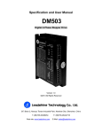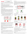
1
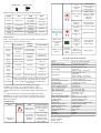
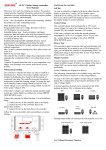
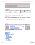
Battery Type
SLAC-H Solar charge controller
User Manual
Factory Settings of the controller is to operate with lead-acid batteries
with liquid electrolyte. If you intend to use a lead-acid battery with solid
electrolyte(Gel type or AGM type), you can adjust the charging
characteristics (see "Settings"). The equalization charge mode is canceled
then. In case of any doubts or questions, please consult your dealer.
Thank you very much for choosing our product. This product manual
provides important information and advices for product installation, use
and troubleshooting. Before using this product, please read carefully and
thoroughly.
Display Functions
The controller is equipped with 5 LEDs and an acoustic warning
signal.
Our product has a number of safety and display functions.
Clear readable LED display of the state of charge.
Acoustic signal when the state of charge changes.
Low voltage disconnect regulated by state of charge or voltage.
The controller adjusts itself automatically to 12V or 24V system voltage.
Max .16 mm² connector binding posts. Max safety current can reach 91A.
The charging characteristics include automatic adoption to the ambient
temperature.
Complete electronic protection.
State of
charge
LED
Charge
LED
Load
status
LED
Wiring and grounding:
The controller is intended for indoor use only or installed in distribution
box. Protect it from direct sunlight and rain. If installed in distribution
box, should avoid the position of condensed water drip. The controller
measures the ambient temperature to adapt the charging voltage. To
ensure the start-up of controller, battery voltage should exceed 10V if the
system voltage is 12V, and battery voltage should exceed 20V if the
system voltage is 24V.
Charge display
Solar array supplies
electricity
Green LED on
If the battery voltage is not within the normal operation range at start-up,
a status display according to the section ERROR DESCRIPTION occurs.
Solar array does not
supply electricity
Green LED off
State of charge display
Connect the controller by following steps to avoid installation faults.
1. Connect the wire to the controller, then to the battery.
2. Connect the wire to the controller, then to the photovoltaic modules.
3. Connect the wire to the load, then to the controller.
A change of the state of charge (SOC) to a lower status is indicated by an
acoustic signal.
80%-100%
High
Follow the reverse procedure when uninstalling to avoid any damage.
30%-80%
Medium
10%-30%
Low
<10%
Very low
Bottom Yellow
Top Yellow
Middle Yellow Bottom Yellow
LED flash
LED on
LED on
LED on
The loads are disconnected approx. 1 minute after a series of 25 tones.
(2)
(1)
Load status display
(3)
In case of deep discharge or overload/short-circuit of load, the load output
is switched off. This is indicated by followings:
All positive connections of SLAC-H controller are common and therefore
have the same electrical potential. If any grounding is required, always do
this on the positive wire. Special grounding terminal can be used for
controller shell grounding.
If the controller is used in a vehicle which has the battery negative on the
chassis, loads connected to the controller must not have an electric
connection to the car body. Otherwise the Low Voltage Disconnect
function and the electronic fuse function of the controller are short
circuited.
Normal operation
Red LED off
REMARK: Mind the recommendations of your battery manufacturer. We
strongly recommend connect a fuse directly to the battery to protect any
short circuit at the battery wiring. The fuse must correspond to 1.5 times
the nominal current of the controller.
LVD protection
Red LED on
Low Voltage Disconnect Function
Overload or over
temperature or
short circuit
Red LED flash
To protect the battery from being deeply discharged, the controller has
following 2 protection modes:
Starting up the controller:
1. State of charge controlled (SOC) : Disconnect at 11.4V/22.8V (at rated
load current) up to 11.9V/23.8 V(At no load current). Factory default
mode for better safe battery protection.
Self Test
As soon as the controller is supplied with power from the battery, it starts
a self test routine. Then the display changes to normal operation.
2. The battery voltage controlled (LVD): Disconnect at 11.0V/22.0 V fixed voltage settings.
The controller adjusts itself automatically to 12V or 24V system. As soon
as the voltage at the time of start-up exceeds 20V, the controller assumes a
24V system.
Setting
After opened the case of controller, there are three jumpers can be seen on
circuit broad: GEL LVD BUZ. The factory setting is Jumper OFF.
If the battery voltage is not within the normal operation range at start-up,
a status display according to the section ERROR DESCRIPTION occurs.
1
Jumper ON
Jumper OFF
With these jumpers, the following settings can be configured:
Jumper
GEL
LVD
BUZ
Function
Battery type
Function of
low voltage
disconnect
Acoustic
alarm signal
Jumper
OFF
Flooded battery
State of charge
controlled
Alarm off
Jumper
ON
Factory
setting
GEL (VRLA
battery)
Flooded battery
Voltage
controlled
State of charge
controlled
flashing
Alarm on
Alarm on
Over
temperature
protect
Cool down the
controller. Load will
be switched
on automatically.
Battery voltage
too high
Check if other
sources overcharge
the battery. If not,
controller is
damaged.
Battery wire or
the fuse is
Check the battery,
damaged,
the fuse and the
battery has high wire. Remove faults.
resistance.
Battery power is
low after a short
time.
Battery
capacity
becomes very
low.
Replace the battery.
Battery is not
being charged
during
daytime.
Solar panels
faulty or
reverse polarity
(green LED
off)
Check the solar
panel and wire.
Remove faults.
Battery wrong
polarity.
All LEDs
Battery is
off. Buzzer
connected with
alarm
reverse polarity.
warning.
Change polarity.
Safety features:
SLAC – H safety features can protect the controller to avoid damage to
products due to incorrect installation or use.
PV terminals
Reverse
polarity
Battery
terminals
Protected(Not at
Protected (buzzer
24V system
alarm warning)
voltage.)
Load terminals
Protected (1)
Short
circuit
Protected (2)
Protected(3)
(with fuse on
battery)
Switches off
immediately(2)
Over
current
Controller will
limit the current.
Protected
Switches off with
a delay (4)
Reverse
charge
Protected
No effect
No effect
Over
voltage
Max. 55V
Max. 55V
Switches off
above
15.5V/31.0 V
Under
voltage
No effect
Switches off load
Switches off
SLAC-H Technical Characteristics
Model
Rated system voltage
Rated battery charging current
Boost charge
Equalization
When over temperature occurs, the controller will limit
the charging current. If the temperature of controller
reaches a high level, the load will automatically be
switched off.
(1) Controller can protect itself, but load might be damaged.
(2) Short circuit current: >4x—6x nominal current, <300 A.
(3) We strongly recommend that add a fuse between battery and
controller. The battery may be permanently damaged when short circuit
occurs.
(4) > 200% rated current: Load will be switched off with 3s delay.
Float charge
Deep discharge protection,
cut-off voltage.
Reconnect level
Under voltage protection.
Over voltage protection.
Max. Charge current.
Max. Load current.
Over
temperature
Self consumption
Warning: Two or more error conditions at the same time may cause
damage to the controller. Always remove the present fault condition
before next operation.
Max. Panel/ Battery voltage
Temperature compensation
(Charge voltage)
Grounding
Battery type
Dimensions (WxHxD)
Installation dimensions
Max. wire size
Ambient temperature
IP grade
Altitude
Net weight
Troubleshooting
Error
Loads are not
supplied
Indication
Cause
Corrective action
Battery is low
(Red LED on)
Load will reconnect
as soon as battery is
recharged.
Over current or
short circuit
(Red LED
flashing)
Switch off all loads.
Remove all errors.
Controller will
switch on load
automatically after
max 1 minute.
Subject to change without notice.
Version: 20140530
Made in China
www.upnetech.com
2
SLAC-H 10A/20A/30A/40A
12V/24V auto recognition
10A 20A 30A 40A
14.5V / 29V(25 °C) 2 h
Activation:
battery voltage < 12.3/24.6 V
14.8V/29.6(25 °C) 2 h
Activation:
battery voltage < 12.1/24.2 V
(at least one time every 30 days)
13.8V / 27.6V(25 °C)
11.4-11.9V/22.8-23.8 V by SOC
11.0/22.0 V by voltage
12.8V/25.6V
10.8V/21.6V
15.5V/31.0 V
10A 20A 30A 40A
10A 20A 30A 40A
4mA-5mA(12V)
5mA-6mA(24V)
55V
-25 mV/K (12 V system)
-50 mV/K (24 V system)
Positive grounding
Lead acid (GEL, AGM, flooded)
140mm*72mm *40mm
130mm*66mm
Max 16mm²
-40°C-+60°C
IP22
≤4000m
280g