1
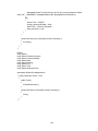
SOLID-MEDICINE CABINET AND INVENTORY
SYSTEM WITH TIME BASED ALARM AND LIGHT
EMITTING DIODE (LED) NOTIFIER
by
Catalan, Neil Carlo P.
Jose, Josiah David D.
Leandicho, Carla Louie H.
A Design Report Submitted to the School of Electrical Engineering,
Electronics Engineering, and Computer Engineering in Partial
Fulfilment of the Requirements for the Degree
Bachelor of Science in Computer Engineering
Mapua Institute of Technology
February 2012
ii
ACKNOWLEDGEMENT
We are sincerely thankful to our adviser, Dionis Padilla, whose
encouragement, guidance and support from the initial to the final level enabled
us to develop an understanding of the subject.
It is a pleasure to extend gratitude to those who made this design
project possible such as our parents who gave us the moral support, and our
friends, Rommer Cañete and Francis Evangelista who helped us in the
programming part of this design project. We also would like to make a special
reference to Ms. Ayra Panganiban who is our professor in design course. Without
her guidance, we could not have completed this design project. We also like to
thank our design panels for giving us the necessary corrections in our
documents.
Lastly, we offer our blessings to everyone who supported us in any
respect during the completion of the project.
iii
TABLE OF CONTENTS
TITLE PAGE
i
APPROVAL SHEET
ii
ACKNOWLEDGEMENT
iii
TABLE OF CONTENTS
iv
LIST OF TABLES
vi
LIST OF FIGURES
vii
ABSTRACT
viii
Chapter 1:
DESIGN BACKGROUND AND INTRODUCTION
1
Overview
Customer
Need
Solution
Benefits
Definition of Terms
1
2
2
3
8
9
REVIEW OF RELATED DESIGN LITERATURE & STUDIES
12
Medicine Dispensers
Microcontroller Unit
Serial Communication from Microcontroller to Computer
12
23
25
DESIGN PROCEDURES
27
Hardware Development
Software Development
Prototype Development
27
31
37
Chapter 4:
TESTING, PRESENTATION, & INTERPRETATION OF DATA
39
Chapter 5:
CONCLUSION AND RECOMMENDATION
44
Conclusion
Recommendation
44
45
Chapter 2:
Chapter 3:
iv
References
47
Appendices
48
A. Operation’s Manual
48
B. Pictures of Prototype
77
C. Data Sheets
82
D. Program Listing
101
E. Price List
135
F. Letter of Intent
136
G. IEEE Format Article of the Design
137
v
LIST OF TABLES
Table 4.1 Expected Action by the MCU with the corresponding input data
Table 4.2 Test for LED Responses on their Respective Drawers
Table 4.3 Test for Buzzer Response
Table 4.4 Test Inputs for the Software Application
Table 4.5 Test for LED Responses on their Respective Drawers with C# code
Table 4.6 Test for Buzzer Response with C# code
vi
LIST OF FIGURES
Figure 2.1: Programmed Medication Dispenser
Figure 2.2: Side-view of Programmed Medication Dispenser
Figure 2.3: Cabinet for Dispensing Medicines at Predetermined Times
Figure 2.3: General Circuit of the McLaughlin’s Invention
Figure 2.4: Perspective of the Portable Medicine Cabinet with Timer
Figure 2.5: Front, Side Elevation and Side View of Medicine Cabinet with Timer
Figure 2.6: The Smart Medical Refrigerator
Figure 2.7: Paper Prototype of a Human-Centered Design of Medicine Dispenser
Figure 3.1: Conceptual Framework
Figure 3.2: Block Diagram of Solid-Medicine Cabinet and Inventory System with
Time Based Alarm and Light Emitting Diode (LED) Notifier
Figure 3.3: Schematic Diagram
Figure 3.4: Program Flow for the Software Application
Figure 3.5: Data Flow Diagram for Scheduling
Figure 3.6: Data Flow Diagram for Inventory
Figure 3.7: Program Flow for PIC16F877A
vii
ABSTRACT
The common causes of medication errors are missing doses, taking incorrect
amounts and taking medicines at the wrong time. These mistakes could lead to
increase discomfort, inadequate diseases prevention and possibly even death of
the patient. The main purpose of this study is to lessen the medication errors
and cost of the hospitals by designing a medicine cabinet. The medicine cabinet
has light indicators in each drawer and an alarm that will notify a nurse if a
particular patient needs medication. It has also inventory system to monitor the
patient’s medicine. It will be developed using a MCU (MicroController Unit), a
high level programming language and a database management system. The MCU
is connected to several LED (Light Emitting Diode), buzzer and to the computer.
We intended to have two tests, which are the LED and alarm testing using UART
terminal and the C# code
Keywords:
UART,
MCU,
LED,
Medicine
viii
cabinet,
Inventory
system
Chapter 1
DESIGN BACKGROUND AND INTRODUCTION
Overview
Hospitals are one of the facilities that are used by people to give them
medical, surgical, or psychiatric treatment and nursing care. It is important to
ensure the safety and security of its patients by giving them right medication,
healthy food, and clean environment. By considering safety and security, the
patient will gain trust to the service of the hospital. Nurses are of big help in a
hospital because they are assigned at the nurse station in each ward where they
manually check the schedule of patient’s time for taking their medicines as
ordered by a doctor.
The common problems that the nurses commit include
having trouble with the patients’ schedule and what medicines they need to
deliver to their patients. It is critical for the nurses to give the right medicine at
its scheduled time of medication to ensure the patient’s safety and health.
Nowadays, hospitals are using different technologies in medication to
ensure the safety of its patient. Before, hospitals are using medicine cabinet that
has compartments for containing supplies of different kinds of medications to be
accessed by a healthcare attendant for preparing individual medication dosages
for named patients. With the use of technology, some of the medicine cabinets
include a processor having a memory for storing the names of patients and their
prescribed medication dosages, and a display screen for displaying the patient
1
names and their respective prescribed medication dosages. The tray includes a
display screen for displaying the patient names and their respective medication
dosages, and a communication link with the medicine cabinet through which the
cabinet processor communicates to the tray the patient names and their
respective medication dosages. Some of the medicine cabinets have an alarm
that will sound reminding the user when medicine shall be taken, and making the
correct dose available. The advantages of this automated medication cabinets is
that it will lower costs associated with pharmaceutical distribution, monitors
inventory, further reduction of errors, and relieving professional pharmacists and
nursing personnel of many tasks.
Customer
Our target customer is Tondo Medical Center located at North Bay
Boulevard, Balut Tondo, Manila. It is a 200-bed capacity tertiary public medical
center established in 1971 by virtue of Republic Act no. 6375.
It presently
operates under the supervision and control of the Department of Health (DOH).
Need
In a Philippine hospital usually a particular nurse is assigned at the nurse
station in each ward where he/she manually checks the schedule of patient’s
time for taking their medicines as ordered by a doctor, and usually a group of
patients is assigned to a nurse, the reason for this is to cut the cost of
expenditures for nurses. This scenario is evident in government hospitals which
lead to an error on the part of the nurses. The assigned nurse is the one who is
2
responsible for preparing the medicine requirement of all the patients he/she
handles in a ward (for example a medical ward).
Also, the assigned nurse
checks the stocks of medicines in the cabinet. With this situation, a need for a
cabinet for solid medicines with time based notifier is required so that the
assigned nurse will not be confused on what slot in the medicine cabinet he/she
will open. If the time comes for taking a medicine, the door of the cabinet will
have an LED indicator then an inventory application in a computer will check
what solid medicines has to be taken out by the assigned nurse and it will check
how much medicine is available, thus simplifying the work of the assigned nurse.
Solution
With the presented problem, the designers came with a solution to
design a solid-medicine cabinet and inventory system with time based alarm and
light emitting diode (LED) notifier.
First it will implement an application for
inventory system that will monitor what medicine should be taken out and check
the quantity of available medicine. And lastly is to notify nurses on the schedule
of patients on his/her medicine intake using an alarm and LED as light signals on
each slot in the cabinet.
The medicine box or shelf which will be comprised of 16 drawers with
16 LEDs beside each drawer particularly at the right position, each drawer has 2”
x 4 ¾” x 1 ¼” dimensions. `
3
Constraints
The constraint/s of the solution in terms of economics is first the solution
requires a good budget in order to install in a particular hospital. The designers
of the solution want to have a plan for actual implementation, but still the return
of investment is not yet considered.
In terms of manufacturability, the solution may require a custom built
cabinet for medicine and the electronic parts which may lead to larger cost
compare with an ordinary cabinet.
And lastly, a computer is needed for the
design solution to work.
In terms of capability, the medicine cabinet is only intended to store solid
medicines for oral medication. The computer is not capable of accessing other
medicine cabinet. Thus, it will provide monitoring on one cabinet only.
In terms of sustainability, the medicine cabinet will use a regular adapter
that is plug in to a regular outlet so sustainability in power source is not yet
considered. In addition, the medicine cabinet is interfaced with the computer
with database which requires maintenance by an expert.
In terms of software application, the solution will require initial inputs on
the stocks of medicine, patient’s name, name of the doctor, time of intake, slot
number on the cabinet, the name of medicine and etc. Next, only the authorized
person can assign the schedule for each nurse on the computer.
connection between the cabinet and computer is not wireless.
Third, the
Fourth, the
software application will use the system clock of the computer. And lastly the
4
software will not recognize if the nurse has taken out the exact quantity of
medicine, the quantity of medicine could be more than or less than the required
number of medicine.
In terms of security, the hardware and software application provide a
low level of security.
Because the designers believe that security is another
scope of the design, futher studies on it will not be included with the scope of
this solution due to time constraints.
Impact
The impact of the design in terms of meeting desired needs to health
and safety is that the design will help the nurses to provide the medication for
the patient in proper time, and they will not be confused because the design will
provide light on LEDs on the slots intended for those patients that are scheduled
to intake their medicine in the cabinet.
Differentiation
Manual method
Almost all hospitals in the Philippines uses a manual method for keeping
medicines and sometimes this method brings a possible cause of accident, like
for example a nurse which gave wrong medicine to a patient.
Difference: Our design proposal lessens the possibility mentioned above by
including a light signal; there will be a slot on the medicine cabinet for the LEDs.
When the medicine needed is inside the drawer, the assigned LED for the said
drawer will light up; otherwise, it will not.
5
Moreover, the proposed system
provides an organize way to remind an individual in the hospital for the patient’s
scheduled medication. The proposed system also keeps track of the medicines
that are being stored and taken out to the patient’s assign drawer, with the use
of the inventory software.
A Medicine Box Prompter Kit Using RFID
Published on June 2008 at Mapúa Institute of Technology
The main key in this design is by the use of radio frequency in alerting
the patient once he or she is out of range, which effectively reminds him or her
to carry important medication before leaving home.
Difference: Our design will be implemented to a hospital particularly at the
medical ward unlike the said project above it is only for a single patient that is
capable of operating the apparatus to take their medication on time. It also uses
RFID technology to remind the patient, while in our design we will use
microcontroller to control the LED to notify the nurse for patient’s medication.
Medication Dispensing System including Medicine Cabinet and Tray therefore
Inventors: Haitin, David and Asseo, Gilead
A medication dispensing system includes a medicine cabinet having a
plurality of compartments for containing supplies of different kinds of
medications to be accessed by a healthcare attendant for preparing individual
medication dosages for named patients; and a tray having a plurality of sections
for receiving a plurality of receptacles each adapted to contain one or more
medication dosages prescribed for a named patient.
6
The medicine cabinet
includes a processor having a memory for storing the names of patients and
their prescribed medication dosages, and a display screen for displaying the
patient names and their respective prescribed medication dosages.
The tray
includes a display screen for displaying the patient names and their respective
medication dosages, and a communication link with the medicine cabinet
through which the cabinet processor communicates to the tray the patient names
and their respective medication dosages.
Difference: Our design project can differentiated from the said invention which
requires a construction of cabinet processor while our design does not need it. In
our design solution we will not include tray with multiple compartments unlike
the design mention above.
Our design solution will use a computer for its
inventory of medicine while the design mention above will use a processor
having a memory for storing the names of patients and their prescribed
medication dosages. So, with the manufacturability of our design much more
simple than one mentioned above.
Cabinet for Dispensing Medicines at Predetermined Times
Inventor: McLaughlin, John T.
A cabinet containing individual compartments each with an individual
time lock for holding various doses of prescribed medicines respectively is
positioned adjacent a given patient’s bed.
The individual time locks are
programmed to open at given times during a 24 hour period at which the
medicine in the corresponding compartment is to be given to the patient.
7
A
signal light advises a nurse whenever any one of the compartments is unlocked.
It is thus assured that the correct dose of the correct prescribed medicine is
given to the correct patient at the correct given time for that particular medicine.
Difference: Our design project can also differentiated to this design because the
said invention is positioned adjacent to a given patient while our project is
located at the medical ward nurse station and our design is only intended for
solid medicine only.
Moreover, our design does not provide a lock one
mentioned above, but our design solution provides a light indicator for each slot
in the cabinet. Our design solution also implements an inventory system that will
keep track on what medicine is disposed from the cabinet in which an added
features than the one mentioned above.
Benefits
The benefits of the proposed system are as follows: First, the checking
of patient’s medicine schedule is automated. Next, it provides safety in picking
the medicines. And it will tell on what medicines was being disposed to patients.
In short, it will serve as an electronic guide to the nurse thus; simplifying his/her
effort which will make his/her do another activity inside the hospital related to
his/her work.
8
Definition of Terms
LED – a light-emitting diode (LED) is a semiconductor device that emits visible
light when an electric current passes through it and serves as light signals on
each cabinet.
Inventory System – the system that will monitor what medicine should be
taken out and check the quantity of available medicine.
Solid Medicine Cabinet - a cabinet which consists of 16 drawers with 16 led’s
and also the allow medicine to be store is only solid.
Time Based Alarm - a buzzer that will notify the nurses on the schedule
patients on his/her medicine intake.
RFID (Radio Frequency Identification) – a technology that incorporates the
use of electromagnetic or electrostatic coupling in the radio frequency (RF)
portion of the electromagnetic spectrum to uniquely identify an object, animal, or
person.
Nursing Care – described as a care given to patients by nursing service
personnel.
Medical Ward – block forming a division of a hospital (or a suite of rooms)
shared by patients who need a similar kind of care.
Smart medical refrigerator – a medical dispenser that monitors whether the
patient took his/her medication.
9
AphA (American Pharmacists Association) - previously known as the
American
Pharmaceutical
Association,
founded
in
1852,
is
the
first-
established professional society of pharmacists within the United States.
MCU (Microcontroller Unit) – a single chip that contains the processor (the
CPU), non-volatile memory for the program (ROM or flash), volatile memory for
input and output (RAM), a clock and an I/O control unit.
RS-232 (Recommended Standard 232) - the traditional name for a series of
standards for serial binary ended data and control signals connecting between a
DTE (Data Terminal Equipment) and a DCE (Data Circuit-terminating
Equipment).
(TTL) Transistor–transistor logic – a class of digital circuits built from bipolar
junction transistors (BJT) and resistors.
It is called transistor–transistor logic
because both the logic gating function (e.g., AND) and the amplifying function
are performed by transistors (contrast with RTL and DTL).
MAX232 – integrated circuit that converts signals from an RS-232 serial port to
signals suitable for use in TTL compatible digital logic circuits. The MAX232 is a
dual driver/receiver and typically converts the RX, TX, CTS and RTS signals.
I²C (pronounced I-squared-C) – created by Philips Semiconductors and
commonly written as ‘I2C’ stands for Inter-Integrated Circuit and allows
communication of data between I2C devices over two wires.
It sends
information serially using one line for data SDA (Serial Data Line) and one for
clock SCL (Serial Clock line).
10
LPT (Line Print Terminal) – the original, and still common, name of the
parallel port interface on IBM PC-compatible computers.
It was designed to
operate a text printer that used IBM’s 8-bit extended ASCII character set.
11
Chapter 2
REVIEW OF RELATED DESIGN LITERATURES AND STUDIES
Medicine Dispensers
Programmed Medication Dispenser, 1968
In the year 1968, John Glucksman’s and Joseph R. Kub’s invention
entitled “Programmed Medication Dispenser (see Figure 2.1 and 2.2)” was
patented. “The invention relates to a timed dispenser device for dispensing at
pre-selected time intervals, any desired dosage, such dispensing action being
accomplished by providing a delivery station communicable with and normally
isolated from storage means for holding a plurality of doses and utilizing a timer
to actuate control means which provide communication at selected intervals and
sensing means responsive to the passage of a dose to the delivery station to
deactivate the timer and thereupon to reactivate the timer when the dose is
removed from the delivery station” (John Glucksman and Joseph R. Kub, 1968).
The said invention aims to have four objectives one was to provide a
timed dispensing apparatus for medications or the like. Second, was to create of
an automatic device in which can be loaded and if in loaded condition will
positively prevent access to the contents. Third, was to create a device that has
sensor for detecting the delivery of a dosage to the delivery station, the sensor
deactivate the timer device if there is a dosage and hence prevent the deposit of
12
a further dose unless the prior dose has been physically removed from the
dispensing station.
And lastly, was to create a device that readily set up to
deliver dosages at selected intervals, the timer mechanism for varying the
dispensing intervals must be flexible so that the dosage schedule may be easily
varied even by an unskilled operator.
Figure 2.1: Programmed Medication Dispenser
Source: John Glucksman and Joseph R. Kub, 1968
13
Figure 2.2: Side-view of Programmed Medication Dispenser
Source: John Glucksman and Joseph R. Kub, 1968
Cabinet for Dispensing Medicines at Predetermined Times, 1973
In the patent paper of John T. McLaughlin, “Cabinet for Dispensing
Medicines at Predetermined Times” the invention was created to minimize the
common errors in carrying out medicines to the patients. They used a cabinet to
create individual compartments for each patient. Each compartment has a time
lock and a signal light. The signal light was created to give the nurse an idea
what compartment the nurse can get the prescribed medicine for the given
patient. The time lock was used to give the prescribed medicine to the patient at
14
the correct time (see Figure 2.3 to have an idea on the appearance of the said
invention).
Figure 2.3: Cabinet for Dispensing Medicines at Predetermined Times
Source: John T. McLaughlin, 1973
The invention was used to ensure that the correct dose of medicine will
be given to the right patient. The time of medication of the patient was
programmed. When it is time for the patient to take its medication, the lock will
be unlocked based on the programmed time and the signal light will notify that
the nurse that it is time for the patient to take its medication. The individual lock
for each compartment was programmed according to the schedule of the
patient. An output signal is passed to a counter and an “OR” circuit (see Figure
15
2.3), the output signal also passes through the master clock and the main signal
light that the program actuates to unlock the associated compartment door.
Another synergizing signal will also be passed to the nurse station to inform the
nurse that it is time for medication of the patient. Setting the time for the
schedule is set by using a counter. The clock pulses determines the time for the
compartment to open.
Figure 2.3: General Circuit of the McLaughlin’s Invention
Source: John T. McLaughlin, 1973
16
Portable Medicine Cabinet with Timer, 1979
In the year 1979 particularly 4th of June, Thurmond Hicks and Brenda
Hicks filed a US patent for their invention “Portable Medicine Cabinet with
Timer”. The purpose of their invention is to assure that an individual does not
both become confused and forget to take doses of certain prescribed medicines,
or take doses of the prescribed medicine too often so as to endanger health
(Hicks T.A. and Hicks B. G., 1981).
The portable medicine cabinet was only intended for private use by an
individual taking several different medicines, in which may be carried from/to the
home, office, and the like.
It comprises a plurality of freely accessible
compartments and time computer into which a plurality of predetermined time
intervals for taking a dose of the respective medicines may be entered (Hicks
T.A. and Hicks B. G., 1981). An indicator is electrically connected to the time
computer which indicates the predetermined time intervals for the medicines
should be removed from its respective compartment.
Thurmond Hicks and Brenda Hicks stated in their paper in the year 1981
that many individuals during that year are taking several prescription drugs the
same period of time and it is believed that a problem exists in keeping track of
the predetermined times for taking a dose of the respective medicines, in which
we can say that is still evident even today.
In fact according to American
Pharmacists Association (AphA) through the report of Institute of Medicine report
in 2006 that 4 of 5 adults take Rx, OTC, or dietary supplement every week, 33%
17
take 5 or more medications weekly, 1.5 million injured by medication errors, and
lastly medication errors cost $3.5 billion.
Therefore, it can be understood that an object of the invention is for the
inventors to provide a portable medicine cabinet with a timer which may be used
by individuals who are taking several medicines at one time and desires aid in
keeping track of the time that a dose of each medicine should be taken. Below
are the drawings of the said invention.
Figure 2.4: Perspective of the Portable Medicine Cabinet with Timer
Source: Hicks T.A. and Hicks B. G., 1981
18
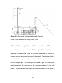
Figure 2.5: Front, Side Elevation and Side View of Medicine Cabinet with Timer
Source: Hicks T.A. and Hicks B. G., 1981
Figure 2.4 is a perspective of the portable apparatus for storing a
plurality of different medicine bottles and indicating at certain predetermined
times that a dose of medicine should be taken.
Figure 2.5 FIG 2 is a front elevation view of the portable apparatus of
invention with the medicine secured within the respective compartments
therefore; FIG 3 is a side elevation view of the portable apparatus of the
invention showing the time computer means in phantom lines within the cabinet;
and FIG 4 is a side view, partly in section, of the portable apparatus of the
present invention with the snap-on cover.
19
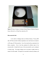
The Smart Medical Refrigerator, 2005
In the article titled “The Smart Medical Refrigerator” by Paul Kuwik,
Thomas Largi, Matt York, Dennis Crump, David Livingston and James C. Squire
they developed a device (see Figure 2.6) that will help elderly diabetics that were
living alone without a nearby family. The smart medical refrigerator is a medical
dispenser that monitors whether the patient took his/her medication. An alarm
and a blinking LED will alert the patient if the patient needs to take the
medication.
The schedule is programmed in a Microcontroller.
It can be
reprogrammed using an externally accessible serial adapter for any change in the
medicine’s dosing schedule. It has a modem that dials to an internet service
provider (ISP) because whenever the patient did not take his/her medicine, it
establishes a simple mail transfer protocol (SMTP) connection to the mail server,
and sends an email to any designated contacts such as doctor, a family member,
and friends to alert them that the patient did not take the medication. Opening
the door was used like an interrupt that will be sending a signal to the
microcontroller that the patient had taken the medication. When the door was
closed during the time of the medication it will send alerts to any designated
email address. This device can also operate during blackouts. While the device
is connected to the house current, it will be automatically recharged to maintain
its peak energy.
It has also a battery level indicator that is used when the
battery is in backup operation. The battery indicator uses Light-emitting diodes
(LEDs) to display the remaining life of the battery.
20
Figure 2.6: The Smart Medical Refrigerator
Source: Paul Kuwik, Thomas Largi, Matt York, Dennis Crump, David Livingston
and James C. Squire, 2005
During the testing process, the problem that they encountered is that the
when the door of the device was not shut. Overall the patient found the device
useful. This device acts like an active-sensor that requires patient interaction to
send out an alarm.
Enhancing Medicine Adherence through Multifaceted Personalized
Medicine Management, 2011
In a research
entitled “Enhancing Medicine
Adherence
through
Multifaceted Personalized Medicine Management”, it was said that medicine
adherence is a growing problem that affects not only patients but also the
healthcare industry (Min-Hui Foo, Jit Chee Chua, Jamie Ng, 2011). The paper
21
presents a brief overview of the severity of medicine non-adherence, especially
to elderly patients of chronic conditions, and the reason behind the phenomenon.
With that the research focuses on the development of a medicine management
system in the form of medicine dispenser and a web portal which attempts to
bring under a single platform to many-sided approach to address medicine
adherence and the benefits that ensue.
The medicine dispenser stores pills which reminds patient when it is time
for medication and dispenses the right dosage to the patient. The web portal
receives and stores medication data from the medicine dispenser. The automatic
reminders and correct dispensing of dosage by the medicine dispenser serve to
increase the patient’s confidence in his or her ability to follow the medication
regimen. Both the medicine dispenser and web portal would incorporate the
function of providing medicine information thus, educating the patient to better
understand their condition and drug therapy. With better knowledge about his
or her condition and the intended effects of the medications, intentional nonadherence and denial of their condition can be subverted. It also enables both
healthcare professional and patient to access the patient’s medicine intake
history, which provides both party with insights and better understanding of
patient’s medicine taking patterns. Below is the figure of the medicine
management system that includes a medicine dispenser and a web portal.
22
Figure 2.7: Paper Prototype of a Human-Centered Design of Medicine Dispenser
Source: Min-Hui Foo, Jit Chee Chua, Jamie Ng, 2011
Microcontroller Unit
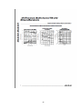
In the article of Wolfgang Abele and Markus Hofmann, “Driving LEDS
with a PIC Microcontroller” different applications were tried that can be tested to
a LED using a PIC Microcontroller. One of the tests that they conducted is the
failure recognition.
First is that they explained the different parts of the
microcontroller. It stated that the pins of the microcontroller can be configured
as analog input.
The analog voltages can be converted to digital values by
means of an A/D module. The signal to be converted is chosen by software, and
23
forwarded to the A/D module.
This module requires reference voltage.
The
voltage can either be applied externally at an input pin, or internally via so-called
voltage reference module. In the latter case, the supply voltage to the PIC must
be kept constant by means of a voltage regulator. For the programming part of
the PIC microcontroller, software is used for creating assembler programs which
are downloaded and executed in the microcontroller. The use of C compiler is
recommended to easily manage and permit changes to readily make.
In this article, they used a matrix connection with a resistor on each LED.
Each LED possesses its own series resistor.
These resistors can be used as
reference resistors for adjusting the current in the diode. If one LED fails, the
remaining LEDs continue to function. When circuit is in a series connection, a
failure would lead to more current in the parallel connected diodes and an
uneven distribution of brightness would arise.
For the failure recognition, they test individual LEDs within an array for
total failure. When an LED leads to a break in path, it causes no current to flow
through the series resistor. The proposed solution here is to use a multiplexer.
The multiplexer can be digitally controlled by the microcontroller. Each LED is
assigned an address which allows it to be selected by the PIC, in order to
determine the current passing through the diode for current regulation or to
assist in failure recognition.
24
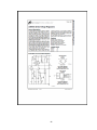
Serial Communication from Microcontroller to Computer
The
article
“Concepts
for
transmitting
data
from
a
PC
to
a
microcontroller” by Ryan Kittredge discussed a serial port interface. An RS232
serial port can be used in transmitting data between PC and the microcontroller.
There are many functions of serial one of the functions is that we can use it for
downloading programs that have been compiled on a microcontroller. There are
drawbacks when using an RS232 because it uses a negative logic.
The
microcontroller uses standard TTL logic so the RS232 signal has to be sent
through another device to convert the negative logic back to TTL. A MAX232
chip can be used to convert the negative logic to TTL and keep the data in serial
format. They also discussed the I2C which is a type of serial communication
developed by Philipps. This technology is widely used in all kinds of electronic
devices. It is a two wire bus, the first wire is the SCL or the Serial Clock line and
the other is the SDA or the Serial Data Line. The two wire bus allows data
transmission between multiple devices. Parallel port interface is also discussed in
this article. There are many benefits in using a parallel port, one of which is that
it is easy to manipulate with the software and the data is transmitted using
standard TTL 0-5v signals. Another benefit is that there is no need to put the
signal back together. A parallel port has a 25 pin connecter on the computer
that is commonly known as printer port, LPT1 or LPT2.
In utilizing the parallel
interface, 8 pins are used for data transmission; 1 pin that signals that the data
is ready and clocks it through, 1 pin to signal whether the data transmission was
25
an address or actual data, and 1 pin to send a signal back to the PC telling that
the current task has been accomplished.
26
Chapter 3
DESIGN PROCEDURES
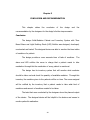
This chapter gives detailed information about the procedures used in
developing the design entitled Solid-Medicine Cabinet and Inventory System with
Time Based Alarm and Light Emitting Diode (LED) Notifier. Software and
Hardware Development are discussed thoroughly in this chapter to guide future
researchers who aspire to innovate the said design.
Hardware Development
This section provides the overview of the steps that the designers
undergo in developing the hardware of the said design. Hardware Development
discusses the components used and the flow of data through the components in
terms of conceptual framework, block diagram and schematic diagram. Major
compositions of this design are discussed in terms of block diagram and
schematic diagram to see the actual circuit comprising of each diagram.
First, the designers researched and gathered information about previous
related designed devices as a basis for circuit design. Second, the designers
chose the right kind of components, then the designers started to simulate the
circuit, after getting the correct output the designer began to develop the said
design. Finally, the designers proceed to testing. While conducting the testing,
some errors were encountered; in this case, the designers proceed in debugging
the device.
27
MICROCONTROLLER
USER INPUT DATA
INPUT
16 LED AND A BUZZER
DEDICATED COMPUTER
MIDDLE DEVICES
OUTPUT
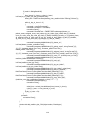
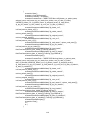
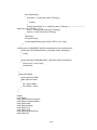
Figure 3.1 Conceptual Framework
Figure 3.1 is the conceptual framework of the proposed system. The
designer used the computer as a middle device that accept inputs from the user
and send a specific command to the microcontroller which serve as a middle
device as well. The computer also monitors the schedule of the patient’s which
helps the nurses to their tasks. The computer will also have inventory software
that will monitor the quantity of the medicines of the patients. The
microcontroller will serve as the driver for the buzzer and the sixteen LEDs.
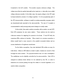
The researchers constructed a block diagram that illustrates the flow of
data in the design of the system which is shown in Figure 3.2.
28
USER INTERFACE, INVENTORY AND
SCHEDULER SYSTEM
COMPUTER
TX
RX
SEND DATA
DATA RECEIVE
SERIAL COMMUNICATION
RX
TX
MCU
LED (LIGHT EMITTING DIODE)
AND BUZZER
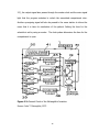
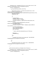
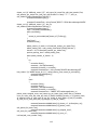
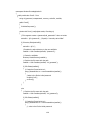
Figure 3.2 Block Diagram of Solid-Medicine Cabinet and Inventory System with
Time Based Alarm and Light Emitting Diode (LED) Notifier
Figure 3.2 shows the block diagram of the solution; it clearly shows that
a computer with the software application is interfaced to the MCU; in this case,
the designers used PIC16F877A. The computer and the MCU communicate with
each other using serial communication; the designers used the USB-to-RS232
converter cable for laptops and netbooks to provide serial connection since most
of the laptops/netbooks don’t have serial port.
29
The buzzer and the 16 LEDs are interfaced to the output ports of the
MCU. The communication between the computer and the MCU can be tested
using a terminal or programmatically.
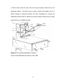
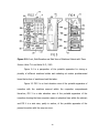
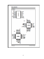
Figure 3.3 Schematic Diagram
Figure 3.3 shows the Schematic diagram for the said solution; LED
number one to eight is attach to the port D of PIC16F877A while LED number
nine to sixteen is attach to port B of the said MCU. Each LED has 470 Ohms
resistor in series to them for the protection of each LEDs. The buzzer is attached
directly to port E pin number 2 of the said MCU. Since the said model of PIC
doesn’t have internal clock the designer provide one, using a 16MHz crystal
together with the two bypass capacitor. The designer adapted the setup of this
external clock to other existing circuits because this is the common setup for an
30
external clock with this kind of MCU. For serial communication the designer used
MAX232 which converts signals from an RS-232 serial port to signals suitable for
use in TTL compatible digital logic circuits. Lastly, the designer placed an inverter
to the DTR pin of the DB9 male in which the inverted signal is then attach to the
MCLR pin of the said MCU; this causes to reset the PIC16F877A if the DTR pin
changes from low to high. The designers do this to have a software-reset
because in C# DTR pin of RS-232 serial port can be altered programmatically.
Software Development
This section provides the overview of the steps that the designers
undergo in developing the software of the said design. Software Development
discusses the program flow and the data flow of the said design. Major
compositions of this design are discussed in terms of flow chart and data flow
diagram to see how the software handles the data and to see what processes
the data should undergo.
31
START
Do you want to
schedule?
NO
Do you want to
check inventory?
YES
YES
Input
patient’s
details
Input
drawer
number
Save patient’s
details
Search medicine
quantity
Cabstorage.dbo
Cabstorage.dbo
NO
END
NO
Extract time of
intake
Add searched
quantity
It is equal to
current time?
Relay updated
medicine quantity
YES
Store information
to notify
Notify.dbo
Notify to scrren
Log notification
Log.dbo
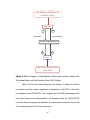
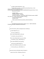
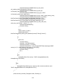
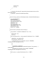
Figure 3.4 Program Flow for the Software Application
Figure 3.4 shows the program flow for the software application. It only
covers the two important feature of the design for simplicity of the presentation.
32
The first feature is the scheduling, once the user wants to schedule he/she must
enter the necessary informations on the application then the application store
those informations in a database table named as “cabstorage”. If the application
is running, it checks the time of intake of each medicine stored in the
“cabstorage” table. Once the time of intake is equal to current time, the
application will place all the necessary information to a database table named as
“notify” then it will relay those information to the user. Every time that the
application notifies the user, it also log those informations that was relayed to
the user. Again the application will store it to another database table called “log”.
The second important feature is the inventory. The application subtracts
a particular quantity to the total quantiy of medicine in a particular dawer. The
subtraction is done when the notification event takes place. The user can check
the inventory in which in return the application will relay the updated quantity of
medicine.
33
Patient’s partial details
Date Today
Drawer number
2
Process Data
Medicine Name
Assigned Doctor
USER
Patient’s full details
Patient’s Name
quantity
Time of intake
Cabstorage.db
o
Patient’s full details
Patient’s Name
1
Get Patient’s
Details
Patient’s full details
Drawer number
Patient’s full details
4
Get Patient’s
full details
6
Update
medicine
details
3
Get Patient’s
full details Patient’s full details
Assigned Doctor
Medicine name
quantity
Time of intake
5
Relay
Patient’s
Details
Patient’s full details
Patient’s full details
Notify.dbo
Log.dbo
Patient’s full details
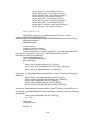
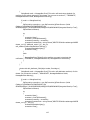
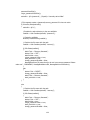
Figure 3.5 Data Flow Diagram for Scheduling
Figure 3.5 and 3.6 show the Data flow Diagram for scheduling and
inventory process respectively, for the software application of this design
solution. Each shape has their meanings which are the following: the circular
shape stands for a process; the rectangular shape stands for storage; and the
arrows stand for data that enter a process or an output of a process.
Figure 3.5 depicts the data flow for scheduling a patient’s time for taking
of his/her medicine/s. Initially, the user will enter the drawer number, name of
patient, assigned doctor and the medicine together with the medicine’s quantity
and time of intake of medicine. Next; at process number 2, it will add the current
date to the patient’s partial details which will become an entry on the database
table “cabstorage.dbo”. If the current time is equal to the scheduled time the
application system will get the patient’s full details and store to table “notify.dbo”
34
and “log.dbo” (see process number 3). The “log.dbo” database table will serve as
a record for all the previous notifications while the “notify.dbo” database table
will serve as container for all the notifications that must be displayed for the user
(see process number 4 and 5). Lastly, the “cabstorage.dbo” database table must
be updated, the updating process include the subtraction to the total quantity
and changing the date for the next medicine intake (see process number 6).
Drawer number
1
Get drawer
number
Drawer number
2
Look for
drawer
number
Drawer number
USER
Cabstorage.db
o
quantity
Inventory Info
4
Relay details
Medicine name
Total quantity
3
Add medicine
quantities
Medicine name
Figure 3.6 Data Flow Diagram for Inventory
Figure 3.6 depicts the Data flow for inventory process. So first the user
must select a drawer number (see process number 1) after that the software
application will get the drawer number assigned, and search all the scheduled
entry on the said drawer, and compare if the drawer number is equal to the
drawer number chosen by the user in “cabstorage.dbo” database table. After
that, process number 3 will get the necessary details for getting the total number
of medicines in the chosen drawer number. Lastly, process 4 will relay all the
content details of the chosen drawer number to the user.
35
START
Initialize
PIC16F877A
NO
Is data
received?
NO
A
B
YES
Is data = “s”?
Is data = “A”
YES
NO
YES
Light off LED1
YES
Light off LED2
YES
Light off LED3
YES
Alarm off
B
NO
Reply “x”
Is data = “B”
Is data
received?
NO
YES
Is data = “C”
Is data = “a”
YES
Light on LED1
NO
NO
Is data = “b”
YES
Is data = “Q”
Light on LED2
NO
Is power off
Is data = “q”
YES
Alarm on
YES
NO
END
A
Figure 3.7 Program Flow for PIC16F877A
36
NO
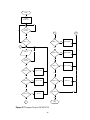
Figure 3.7 shows how the PIC16F877A program flows. First, PIC16F877A
will initialize the ports assigned for each LEDs and Buzzer. PIC16F877A will wait
for the character letter “s”, the sending of this letter serve as a triggering event
for the PIC16F877A to start its job; automatically PIC16F877A will send a reply
letter “x”.
There are specific letters assigned for each LED and buzzer. Small letters
from “a” to “p” is assigned to switch on the LEDs and capital letters from “A” to
“P” is assigned to turn off the LEDs. Small letter and capital letter is assigned for
a specific drawer. For example, small “a” is assigned to turn on the LED in the
first drawer and capital “A” is assigned to turn off the LED in the same drawer.
For the second drawer letters “b” and “B” are used so on.
Small letter “q” is assigned to turn on the buzzer and small letter “Q” is
assigned to off the buzzer. The buzzer will be in on state if letter “q” is sent
serially, but not until “Q” is sent. The software application is the one who
responsible for how long will the buzzer will be at its on state.
Therefore, one of the tasks of the software application is to send and
receive data coming from/to the PIC16F877A. With that in effect the software
application controls the sixteen LED and the buzzer, while the microcontroller
serve as the driver for the sixteen LED and the buzzer.
Prototype Development
This section provides the overview of the steps that the designers
undergo in developing the prototype of the said design.
37
The designers used the following software application in the prototype
development Visual Studio 2010 Professional, MikroC v3.2, and Proteus 7
Professional. First, the designers gather information about the design of the
circuit. Second, the designers construct the circuit and simulate it using a
software simulator; in this case, the designers used Proteus 7 Professional. Third,
the designers made a version of the circuit in breadboard. Fourth, the designers
programmed the PIC16F877A microcontroller using MikroC v3.2, and then the
designers tested it. Fifth, the designers started to code the software application
using Visual Studio 2010; then the designers integrated the circuit with the
software application and tested it to identify errors. And lastly, after the
correction of errors the designers assembled the circuit in Printed Circuit Board
or PCB then tested the whole design system with respect with the objectives
presented in chapter one.
38
Chapter 4
TESTING, PRESENTATION, AND INTERPRETATION OF DATA
This chapter discusses the various tests conducted in relation to the
stated objectives in Chapter 1 to determine the functionality and reliability of the
created prototype.
Before the test, the researchers planned to have five trials on each
drawer as well as with the buzzer.
Using the UART terminal in Mikro C the
researchers send an ASCII character to the COM port of the computer then
eventually the microcontroller will interpret that character to a command that will
turn on or turn off a particular LED on the drawer or will alarm the buzzer.
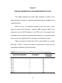
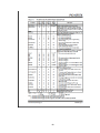
Table 4.1 shows the output action of the microcontroller to a specific
data input. Table 4.1 serves as the basis for determining if a data sent was
successfully interpreted by the microcontroller.
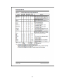
Table 4.1 Expected Action by the MCU with the corresponding input data
AFFECTED COMPONENT
LED
LED
LED
LED
LED
LED
LED
LED
LED
LED
LED
1
2
3
4
5
6
7
8
9
10
11
STATE OF THE
COMPONENT
(OUTPUT)
DATA INPUT
a
b
c
d
e
f
g
h
i
j
k
ON
ON
ON
ON
ON
ON
ON
ON
ON
ON
ON
39
Table 4.1 Expected Action by the MCU with the corresponding input data
(Continuation)
AFFECTED COMPONENT
LED 12
LED 13
LED 14
LED 15
LED 16
ALARM
LED 1
LED 2
LED 3
LED 4
LED 5
LED 6
LED 7
LED 8
LED 9
LED 10
LED 11
LED 12
LED 13
LED 14
LED 15
LED 16
ALARM
STATE OF THE
COMPONENT
(OUTPUT)
DATA INPUT
l
m
n
o
p
q
A
B
C
D
E
F
G
H
I
J
K
L
M
N
O
P
Q
ON
ON
ON
ON
ON
ON
OFF
OFF
OFF
OFF
OFF
OFF
OFF
OFF
OFF
OFF
OFF
OFF
OFF
OFF
OFF
OFF
OFF
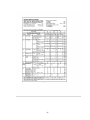
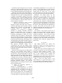
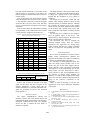
Table 4.2 and 4.3 show the collected data in testing the functionality of
the LED and the buzzer of the created prototype, using the UART terminal in
Mikro C. The test ensures that the researchers are successful in creating the
hardware component of the design solution that has a light signal on each
drawer and an alarm. With that, the researchers assumed that every command
signal that was sending though serial communication has a corresponding action
by the microcontroller unit.
40
Table 4.2 Test for LED Responses on their Respective Drawers
Drawers
LED
1
2
3
4
5
6
7
8
9
10
11
12
13
14
15
16
1
2
3
4
5
6
7
8
9
10
11
12
13
14
15
16
Trial 1
(ON)
Trial 2
(OFF)
Trial 3
(ON)
Trial 4
(OFF)
Trial 5
(ON)
SUCCESS
SUCCESS
SUCCESS
SUCCESS
SUCCESS
SUCCESS
SUCCESS
SUCCESS
SUCCESS
SUCCESS
SUCCESS
SUCCESS
SUCCESS
SUCCESS
SUCCESS
SUCCESS
SUCCESS
SUCCESS
SUCCESS
SUCCESS
SUCCESS
SUCCESS
SUCCESS
SUCCESS
SUCCESS
SUCCESS
SUCCESS
SUCCESS
SUCCESS
SUCCESS
SUCCESS
SUCCESS
SUCCESS
SUCCESS
SUCCESS
SUCCESS
SUCCESS
SUCCESS
SUCCESS
SUCCESS
SUCCESS
SUCCESS
SUCCESS
SUCCESS
SUCCESS
SUCCESS
SUCCESS
SUCCESS
SUCCESS
SUCCESS
SUCCESS
SUCCESS
SUCCESS
SUCCESS
SUCCESS
SUCCESS
SUCCESS
SUCCESS
SUCCESS
SUCCESS
SUCCESS
SUCCESS
SUCCESS
SUCCESS
SUCCESS
SUCCESS
SUCCESS
SUCCESS
SUCCESS
SUCCESS
SUCCESS
SUCCESS
SUCCESS
SUCCESS
SUCCESS
SUCCESS
SUCCESS
SUCCESS
SUCCESS
SUCCESS
Percentage
of Success
(%)
100
100
100
100
100
100
100
100
100
100
100
100
100
100
100
100
Table 4.3 Test for Buzzer Response
Buzzer
Alarm
Percentage
of Success
(ON)
(OFF)
(ON)
(OFF)
(ON)
(%)
SUCCESS SUCCESS SUCCESS SUCCESS SUCCESS 100
Trial 1
Trial 2
Trial 3
Trial 4
Trial 5
The percentage of success was computed based on a formula that can
be express as
(3.1)
As clearly seen in table 4.2 and 4.3, the medicine cabinet was
successfully responsded to every data input.
But during the design process another problem arises which lead to the
question about the response of the microcontroller unit to the command send by
the C# program. With this question, the designers choose test inputs for the
41
application software. Since the main function of this solution is to schedule a
patient’s time of intake, the designers constructed table 4.4.
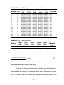
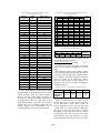
Table 4.4 Test Inputs for the Software Application.
Trial 1
Trial 2
Trial 3
Software
12 am
7:30 am
12 pm
Application
Inputs
Trial 4
7:30 pm
Table 4.4 represents the test inputs for the software application. The
time in trial 1 and trial 3 are the two extreme input values because the software
application converts the time input from 12 hour format to 24 hour format; in
converting a time from 12 hour to 24 hour format it is known that adding 12 to
the hour part of time is necessary for those time after noon, and those time
before noon remain the same. But if the time is 12 pm it should remain the
same and if the time is 12 am the hour part must be subtracted to 12, because
of this diffirent process in converting 12 am and 12 pm time the designers
considered these times as the two extreme values.
Now, to represent a time between those extreme values the designer
chose the time in trial 2 and trial 4. The said table is necessary so that the
designers would not take every time in the clock, this table serve as a
representative time inputs to the software application.
Table 4.5 and 4.6 show the collected data in testing the functionality of
the LED and the buzzer of the created prototype, using the trials in table 4.4.
42
Table 4.5 Test for LED Responses on their Respective Drawers with C# code
Drawers
1
2
3
4
5
6
7
8
9
10
11
12
13
14
15
16
LED
1
2
3
4
5
6
7
8
9
10
11
12
13
14
15
16
Trial 1
Trial 2
Trial 3
Trial 4
SUCCESS
SUCCESS
SUCCESS
SUCCESS
SUCCESS
SUCCESS
SUCCESS
SUCCESS
SUCCESS
SUCCESS
SUCCESS
SUCCESS
SUCCESS
SUCCESS
SUCCESS
SUCCESS
SUCCESS
SUCCESS
SUCCESS
SUCCESS
SUCCESS
SUCCESS
SUCCESS
SUCCESS
SUCCESS
SUCCESS
SUCCESS
SUCCESS
SUCCESS
SUCCESS
SUCCESS
SUCCESS
SUCCESS
SUCCESS
SUCCESS
SUCCESS
SUCCESS
SUCCESS
SUCCESS
SUCCESS
SUCCESS
SUCCESS
SUCCESS
SUCCESS
SUCCESS
SUCCESS
SUCCESS
SUCCESS
SUCCESS
SUCCESS
SUCCESS
SUCCESS
SUCCESS
SUCCESS
SUCCESS
SUCCESS
SUCCESS
SUCCESS
SUCCESS
SUCCESS
SUCCESS
SUCCESS
SUCCESS
SUCCESS
Percentage
of Success
(%)
100
100
100
100
100
100
100
100
100
100
100
100
100
100
100
100
Table 4.6 Test for Buzzer Response with C# code
Buzzer
Alarm
Trial 1
Trial 2
Trial 3
Trial 4
SUCCESS
SUCCESS
SUCCESS
SUCCESS
Percentage
of Success
(%)
100
Table 4.5 and 4.6 show the response of the light signal and the alarm
with the test inputs of the software application it clearly shows that the solution
responded to a particular scheduled time. Again the percentage of success was
measured using equation 3.1.
43
Chapter 5
CONCLUSION AND RECOMMENDATION
This
chapter
states
the
conclusion
of
the
design
and
the
recommendation by the designers for the design’s further improvements.
Conclusion
The design Solid-Medicine Cabinet and Inventory System with Time
Based Alarm and Light Emitting Diode (LED) Notifier was designed, developed,
constructed and tested. The designed device was able to monitor the time intake
of medicine of a patient.
The design provides a more accurate time of take of medicine.
The
alarm and LED notifies the nurse in charge that a patient needs to take
medication through this the medication of every patient is monitored.
The design has its inventory system that will monitor what medicine
should be taken out and check the quantity of available medicine. Through this
inventory the medicine given to the patients will be on time. The nurse assigned
will be notified by the inventory that a patient needs to take what kind of
medicines and amount of medicine needed to be taken.
The tests that were conducted by the designers show the planned output
of the device. The designed device will be helpful to the doctors and nurses to
monitor patient’s medication.
44
The researchers were able to conclude the following through testing:
First, the solution responded to the signal that was sending using UART terminal
and lastly the solution responded with the C# program at corresponding user’s
test inputs.
Recommendation
The following are recommended ways to improve the design:
In terms of hardware security, the medicine cabinet with multiple
drawers is can be opened by anyone, thus the cabinet is not secured by illegal
access of the drawers. But this problem can be address by providing a locking
mechanism in each drawer.
In terms of software security, the software application only provides a
simple password protection. Future study is required to provide a more secured
software application.
In terms of medicine quantity monitoring, the whole system cannot
detect if the quantity recorded by the software application is equal to real
quantity in a drawer. This problem can be address by providing a monitoring
system that can be integrated with this design project.
In terms of the medicine cabinet size, the size of the drawer and the
cabinet is not limited to what is presented in this paper.
In terms of the design of user interface as well as its functionality, the
design of the software application is not limited to what is presented in this
paper.
45
In terms of compatibility of the software application to other operating
system, this paper only presented a software application that is compatible for
Windows operating system, but it can be extend to other operating system.
46
REFERENCES
Glucksman J., et al, (1968). Programmed Medication Dispenser.
McLaughlin J. T., (1973). Cabinet for Dispensing Medicines at Predetermined
Times.
Hicks T. A. and Hicks B. G., (1981). Portable Medicine Cabinet with Timer.
Hopkins W. G., (2000). Summarizing Data: Precision of Measurement.
Aberle W., Hofman M., (2003). Driving LEDs with a PIC Microcontroller.
Kittredge R., (2003). Concepts for Transmitting Data from a PC to a
Microcontroller.
Kuwik P., Thomas L., York M., Crump D., Livingston D. and Squire J. C., (2005).
The Smart Medical Refrigerator.
Foo M., Chua J., Ng J., (2011). Enhancing Medicine Adherence through
Multifaceted Personalized Medicine Management.
47
APPENDIX
A.
Operation’s Manual
System Requirement
These are the requirements necessary to operate the device. It should
be a laptop or a computer with the following features:
1.
Windows Operating System: Windows XP and newer versions
2.
USB Port
3.
Microsoft .NET Framework 4 Client Profile
4.
Minimum Memory of 512MB
5.
RS232 Serial port
6.
USB-to-RS232 Converte (for laptops)
Installation Procedure
1.
Connect the 9-V adapter to the medicine cabinet.
2.
Connect the medicine cabinet to a RS232 serial port of a PC. If it is
a laptop connect first the USB-to-RS232 converter to a USB port,
then connect it to the medicine cabinet.
3.
Install Microsoft .NET Framework for the software.
48
User’s Manual
Opening the application:
1. Double click the .exe file.
2. A message box will appear indicating that the application found the device.
Click “OK”.
49
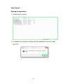
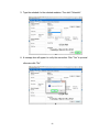
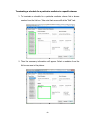
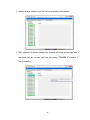
3. After clicking the “OK” button the main form will appear, take note that the
first activated tab is the “Notification” tab.
Using the notification tab:
1. If a notification appeared as seen in the picture, the user can clear the
area by clicking the “Clear” button.
50
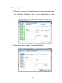
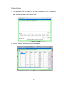
2. A message box will appear to verify the action of the user. Just click “Yes”
if you want to proceed otherwise click “No”.
3. To turn off a particular light in a drawer select first the associated drawer
number among the choices in the application. For the picture below
drawer 2 is on, so we will select drawer 2.
51
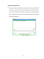
4. Then click the “Off” button.
5. A message box will appear which will verify the user action. Click “Yes” if
you want to proceed otherwise click “No”.
52
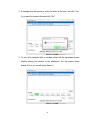
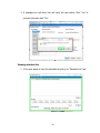
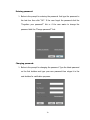
Scheduling:
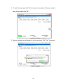
1. To schedule a medication for a patient go to “Schedule” tab. A password
is required for this action.
2. Enter the initial password (“neil”). The user can change the password
later.
53
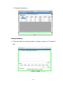
3. Type the necessary information in the form.
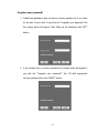
4. Select a medicine from the list box as seen in the picture. The user can
add medicine by typing the name at the “Medicine Name” then click
“Add”. The user can also delete a medicine from the list just select first a
medicine name from the list box then click “Delete”.
54
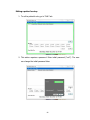
5. Type the schedule for the selected medicine. Then click “Schedule”.
6. A message box will appear to verify the user action. Click “Yes” to proceed
otherwise click “No”.
55
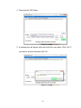
Editing a patient’s entry:
1. To edit a patient’s entry go to “Edit” tab.
2. This action requires a password. Enter initial password (“neil”). The user
can change the initial password later.
56
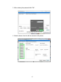
3. After entering the password click “Ok”.
4. Select a drawer from the list box as seen in the picture.
57
5. After selecting a drawer number it will give you the patient, doctor and
the medicine informations, the user can now alter these information.
6. After altering click “Save”.
58
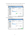
7. A message box will appear, this will verify the user action click “Yes” to
proceed otherwise click “No”.
8. A message box will appear indicating that the saving of the data was
done.
59
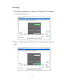
Terminating a schedule for a particular medicine in a specific drawer:
1. To terminate a schedule for a particular medicine choose first a drawer
number from the list box. Take note that we are still at the “Edit” tab.
2. Then the necessary information will appear. Select a medicine from the
list box as seen in the picture.
60
3. Click “Terminate” button.
4. A message box will appear this will verify the user action. Click “Yes” to
proceed; otherwise, click “No”.
61
Deallocating a drawer:
1. The user can remove the assigned patient to a drawer; this can be done
by clicking the “Deallocate” button. Just be careful with this action
because this will remove all the information in a drawer.
2. First, select a drawer number. Then, click “Deallocate”.
62
3. A message box will show, this will verify the user action. Click “Yes” to
proceed otherwise click “No”.
Viewing schedule list:
1. If the user wants to view the schedule list just go to “Schedule List” tab.
63
2. Then the list will show.
Viewing inventory:
1. If the user wants to view the content of a drawer, just go to to “Inventory”
tab.
64
2. Select a drawer number from the list box as shown in the picture.
3. After selection of drawer number the contents will show at the right side of
the active tab. As you can see from the picture “DRAWER 1” contains “0”
(zero) medicine.
65
Viewing history:
1. The application has the ability to log every notification in the “Notification”
tab. This can be seen at the “History” tab.
2. Goto to “History” tab then the log list will appear.
66
Using the maintenance tab:
1. If the user wants to check the lights in each drawer, the buzzer, and the COM
port number, or the user wants to reset the hardware part of this system; the
user can go to “Maintenance” tab. Take note that this is password protected
like the “Schedule” and the “Edit” tab, so with that the same process applies
in entering the password.
67
2. To test the light in each drawer, select a drawer number among the choices
then click “On” this will turn on the light otherwise if the user wants to turn
off the light click “Off”.
3. Again a message box will appear to verify the user action. Click “Yes” to
proceed otherwise click “No”.
68
4. To test the buzzer just click “On” as shown in the picture if the user wants to
turn off the buzzer click “Off”.
5. Again a message box will appear to verify user action. Click “Yes” to proceed.
69
6. If the user wants to reset the hardware just click the “Reset” button. Be
careful in doing this because this will reinitialize the device.
7. A message box will appear. Click “Yes” if you want o proceed.
70
8. If the reset was succesfull a message box will appear indicating that the
application found the device.
9. If the user wants to know the port used by the device click “Show” button.
71
10. A message box will appear indicating the port number.
72
Entering password:
1. Below is the prompt for entering the password. Just type the password in
the text box then click “OK”. If the user forgot the password click the
“Forgotten your password?” link or if the user wants to change the
password click the “Change password?” link.
Changing password:
1. Below is the prompt for changing the password. Type the latest password
on the first textbox next type your new password then retype it in the
next textbox for verification purposes.
73
Forgotten your password?
1. Initially the application does not have a recovery password so it is a must
for the user to set it first. If you click the “Forgotten your password” link
the prompt below will appear. After filling up the textboxes click “SET”
button.
2. If you already have a recovery password the prompt below will appear if
you click the “Forgotten your password?” link. Fill with appropriate
recovery password then click “RESET” button.
74
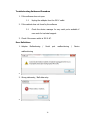
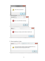
Troubleshooting Guides and Procedure
1. If the software does not open
1.1
Unplug the adalpter from the 220 V outlet
2. If the cabinet does not found by the software
2.1
Check the device manager for any serial ports available if
none seek for technical support.
3. Check if the source outlet is 220 V AC.
Error Definitions
1. Adapter
Malfuntioning
/
Serial
malfunctioning
2. Wrong data entry / Null data entry
75
port
malfunctioning
/
Device
3. Wrong connections of ports
76
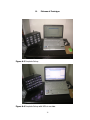
B.
Pictures of Prototype
Figure A.3 Complete Set-up
Figure A.4 Complete Set-up with LEDs in on state
77
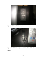
Figure A.5 AC Power Adaptor Unregulated.
Figure A.6 RS232 Female (below) attach to USB-to-RS232 Male converter
(above)
78
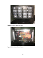
Figure A.7 Medicine Cabinet Front View
Figure A.8 Rear View of Medicine Cabinet
79
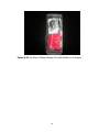
Figure A.9 Front View of Drawer Number Two
Figure A.10 Top View of Drawer Number Two with Medicine Tablets
80
Figure A.11 Top View of Drawer Number Two with Medicine in a Wrapper
81
C.
Data Sheets
82
83
84
85
86
87
88
89
90
91
92
93
94
95
96
97
98
99
100
D.
Program Listing
Mikro C v3.2 Program Listing
char read, error;
int i = 0x00, j = 0x00, q = 0;
void main()
{
ADCON1=6;
CCP1CON=0x00;
TRISB = 0x00; // port b as output
TRISD = 0x00; // port d as output
TRISE = 0x00; // port e as output
PORTB = 0x00;
// turn off LED
PORTD = 0x00;
// turn off LED
PORTE = 0x00; // turn off PORT E
UART1_Init(9600);
Delay_ms(100);
// Initialize UART module at 9600 bps
// Wait for UART module to stabilize
while (1) // Endless loop
{
if (UART1_Data_Ready())
// If data is received
{
read = UART1_Read(); // read the received data
if (read == 's')
{
UART1_Write('x');
break;// exit loop
}
}
}
while(1)
{
start:
if (UART1_Data_Ready())
// If data is received
{
read = UART1_Read(); // read the received data
switch(read)
{
case 'a': {PORTD = i;
RD0_bit = 1;
i = PORTD;}
break;
case 'A': {PORTD = i;
RD0_bit = 0;
i = PORTD;}
101
break;
case 'b': {PORTD = i;
RD1_bit = 1;
i = PORTD;}
break;
case 'B': {PORTD = i;
RD1_bit = 0;
i = PORTD;}
break;
case 'c': {PORTD = i;
RD2_bit = 1;
i = PORTD;}
break;
case 'C': {PORTD = i;
RD2_bit = 0;
i = PORTD;}
break;
case 'd': {PORTD = i;
RD3_bit = 1;
i = PORTD;}
break;
case 'D': {PORTD = i;
RD3_bit = 0;
i = PORTD;}
break;
case 'e': {PORTD = i;
RD4_bit = 1;
i = PORTD;}
break;
case 'E': {PORTD = i;
RD4_bit = 0;
i = PORTD;}
break;
case 'f': {PORTD = i;
RD5_bit = 1;
i = PORTD;}
break;
case 'F': {PORTD = i;
RD5_bit = 0;
i = PORTD;}
break;
case 'g': {PORTD = i;
RD6_bit = 1;
i = PORTD;}
break;
case 'G': {PORTD = i;
RD6_bit = 0;
i = PORTD;}
break;
case 'h': {PORTD = i;
RD7_bit = 1;
i = PORTD;}
break;
102
case 'H': {PORTD = i;
RD7_bit = 0;
i = PORTD;}
break;
case 'i': {PORTB = j;
RB0_bit = 1;
j = PORTB;}
break;
case 'I': {PORTB = j;
RB0_bit = 0;
j = PORTB;}
break;
case 'j': {PORTB = j;
RB1_bit = 1;
j = PORTB;}
break;
case 'J': {PORTB = j;
RB1_bit = 0;
j = PORTB;}
break;
case 'k': {PORTB = j;
RB2_bit = 1;
j = PORTB;}
break;
case 'K': {PORTB = j;
RB2_bit = 0;
j = PORTB;}
break;
case 'l': {PORTB = j;
RB3_bit = 1;
j = PORTB;}
break;
case 'L': {PORTB = j;
RB3_bit = 0;
j = PORTB;}
break;
case 'm': {PORTB = j;
RB4_bit = 1;
j = PORTB;}
break;
case 'M': {PORTB = j;
RB4_bit = 0;
j = PORTB;}
break;
case 'n': {PORTB = j;
RB5_bit = 1;
j = PORTB;}
break;
case 'N': {PORTB = j;
RB5_bit = 0;
j = PORTB;}
break;
case 'o': {PORTB = j;
103
RB6_bit = 1;
j = PORTB;}
break;
case 'O': {PORTB = j;
RB6_bit = 0;
j = PORTB;}
break;
case 'p': {PORTB = j;
RB7_bit = 1;
j = PORTB;}
break;
case 'P': {PORTB = j;
RB7_bit = 0;
j = PORTB;}
break;
case 'q': {RE2_bit = 1;}
break;
case 'Q': {RE2_bit = 0;}
break;
default: {goto start;}
}
}
}
}
Microsoft Visual Studio 2010 C# Program Listing
FORM1:
using System;
using System.Collections.Generic;
using System.ComponentModel;
using System.Data;
using System.Drawing;
using System.Linq;
using System.Text;
using System.Windows.Forms;
using System.Data.SqlClient;
using System.IO.Ports;
using System.Threading;
using System.Collections.ObjectModel;
using System.Diagnostics;
namespace WindowsFormsApplication8
{
public partial class Form1 : Form
{
string[] PORTNAME = SerialPort.GetPortNames();
string drw_no;
char READ_DATA_FROM_MCU;
int PORTNAME_INDEX = 0, NOTIFY_ARRAY_INDEX = 0;
bool search;
DateTime sched_time;
104
Collection<string> notify_array = new Collection<string>();
Thread crossThread = null;
delegate void SetTextCallback();
private delegate void RefreshTabPageDelegate(int tabPage);
public Form1()
{
InitializeComponent();
}
private void Form1_Load(object sender, EventArgs e)
{
this.logTableAdapter.Fill(this._C__PROGRAM_FILES_MICROSOFT_SQL_SERVER_MSSQL10_50_M
SSQLSERVER_MSSQL_DATA_MEDCAB_MDFDataSet1.log);
this.cabstorageTableAdapter.Fill(this._C__PROGRAM_FILES_MICROSOFT_SQL_SERVER_MSSQL1
0_50_MSSQLSERVER_MSSQL_DATA_MEDCAB_MDFDataSet.cabstorage);
foreach (string s in PORTNAME)
{
try
{
port.PortName = s;
port.ReadTimeout = 100;
port.Open();
port.Write("s");
READ_DATA_FROM_MCU = (char)port.ReadChar(); //read data from PIC16F877A
then stored to buffer
if (READ_DATA_FROM_MCU == 'x')
{
MessageBox.Show("You may now use the application the medicine cabinet is
connected to: " + PORTNAME[PORTNAME_INDEX], "COM port", MessageBoxButtons.OK,
MessageBoxIcon.Information);
port.Close();
break;
}
}
catch (Exception a)
{
}
port.Close();
PORTNAME_INDEX++;
}
if (READ_DATA_FROM_MCU != 'x')
{
DialogResult result = MessageBox.Show("Cannot locate medicine cabinet; it might be
unplugged or the mcu is not properly reset upon closing! (press OK to exit)", "COM port",
MessageBoxButtons.OK, MessageBoxIcon.Exclamation);
if (result == DialogResult.OK)
{
goto theEnd;
}
105
}
SqlConnection connection = new SqlConnection(@"Data Source=.;Initial
Catalog=C:\PROGRAM FILES\MICROSOFT SQL
SERVER\MSSQL10_50.MSSQLSERVER\MSSQL\DATA\MEDCAB.MDF;Integrated Security=True");
SqlCommand command;
SqlDataReader read;
connection.Open();
command = new SqlCommand();
command.Connection = connection;
command.CommandText = "SELECT * FROM dbo.medicine ORDER BY med_name ASC";
command.ExecuteNonQuery();
read = command.ExecuteReader();
while (read.Read())
{
medicine_listBox.Items.Add(read["med_name"].ToString());
}
read.Close();
connection.Close();
search = true;
backgroundWorker1.RunWorkerAsync();
timer1.Start();
goto Go;
theEnd:
Close();
Go:;
}
private void Form1_FormClosing(object sender, FormClosingEventArgs e)
{
if (READ_DATA_FROM_MCU == 'x')
{
port.DtrEnable = true;
port.Open();
port.Close();
port.DtrEnable = false;
port.Open();
port.Close();
}
}
private void timer1_Tick(object
{
Current_Date_Time1.Text =
Current_Date_Time2.Text =
Current_Date_Time3.Text =
}
sender, EventArgs e)
DateTime.Now.ToString("f");
DateTime.Now.ToString("hh:mm tt");
DateTime.Now.ToLongDateString();
106
private void tabControl1_Selected(object sender, EventArgs e)
{
if (tabControl1.SelectedTab == tabControl1.TabPages["Schedule_tab"])
{
Form2 form2 = new Form2();
form2.ShowDialog();
if (MgaVar.okbut == true)
{
MgaVar.okbut = false;
this.AcceptButton = schedule_but;
}
else
{
tabControl1.SelectTab(Notification_tab);
}
}
if (tabControl1.SelectedTab == tabControl1.TabPages["Notification_tab"])
{
this.AcceptButton = notification_off_switch_but;
}
if (tabControl1.SelectedTab == tabControl1.TabPages["Edit_tab"])
{
Form2 form2 = new Form2();
form2.ShowDialog();
if (MgaVar.okbut == true)
{
MgaVar.okbut = false;
edit_drawer_listBox.SelectedIndex = -1;
this.AcceptButton = edit_save_but;
}
else
{
tabControl1.SelectTab(Notification_tab);
}
}
if (tabControl1.SelectedTab == tabControl1.TabPages["Inventory_tab"])
{
inventory_drawer_listBox.SelectedIndex = -1;
}
if (tabControl1.SelectedTab == tabControl1.TabPages["schedule_list_tab"])
{
cabstorageTableAdapter.Fill(_C__PROGRAM_FILES_MICROSOFT_SQL_SERVER_MSSQL10_50_MS
SQLSERVER_MSSQL_DATA_MEDCAB_MDFDataSet.cabstorage);
schedule_list_dataGridView.Refresh();
}
if (tabControl1.SelectedTab == tabControl1.TabPages["Log_tab"])
{
this.AcceptButton = print_but;
logTableAdapter.Fill(_C__PROGRAM_FILES_MICROSOFT_SQL_SERVER_MSSQL10_50_MSSQLSER
VER_MSSQL_DATA_MEDCAB_MDFDataSet1.log);
107
log_dataGridView.Refresh();
}
}
//############MAINTENANCE TAB #############################
private void light_test_selectall_checkBox_CheckedChanged(object sender, EventArgs e)
{
if (tabControl1.SelectedTab == tabControl1.TabPages["Maintenance_tab"])
{
foreach (CheckBox chkbox in light_test_groupBox.Controls)
{
chkbox.Checked = light_test_selectall_checkBox.Checked;
}
}
if (tabControl1.SelectedTab == tabControl1.TabPages["Notification_tab"])
{
foreach (CheckBox chkbox in notification_off_switch_gruopBox.Controls)
{
chkbox.Checked = notification_selectall_checkBox.Checked;
}
}
}
private void light_test_on_but_Click(object sender, EventArgs e)
{
DialogResult result = MessageBox.Show("Warning this action will turn on the selected
LED/s on the cabinet! Do you want to continue?", "Light Test", MessageBoxButtons.YesNo,
MessageBoxIcon.Warning);
if (result == DialogResult.Yes)
{
foreach (CheckBox chkbox in light_test_groupBox.Controls)
{
if (chkbox.Checked == true)
{
port.Open();
switch (chkbox.Text)
{
case "Drawer1": port.Write("a"); break;
case "Drawer2": port.Write("b"); break;
case "Drawer3": port.Write("c"); break;
case "Drawer4": port.Write("d"); break;
case "Drawer5": port.Write("e"); break;
case "Drawer6": port.Write("f"); break;
case "Drawer7": port.Write("g"); break;
case "Drawer8": port.Write("h"); break;
case "Drawer9": port.Write("i"); break;
case "Drawer10": port.Write("j"); break;
case "Drawer11": port.Write("k"); break;
case "Drawer12": port.Write("l"); break;
case "Drawer13": port.Write("m"); break;
case "Drawer14": port.Write("n"); break;
case "Drawer15": port.Write("o"); break;
108
case "Drawer16": port.Write("p"); break;
}
port.Close();
}
}
}
}
private void light_test_off_but_Click(object sender, EventArgs e)
{
DialogResult result = MessageBox.Show("Warning this action will turn off the selected
LED/s on the cabinet! Do you want to continue?", "Warning", MessageBoxButtons.YesNo,
MessageBoxIcon.Warning);
if (result == DialogResult.Yes)
{
if (tabControl1.SelectedTab == tabControl1.TabPages["Maintenance_tab"])
{
foreach (CheckBox chkbox in light_test_groupBox.Controls)
{
if (chkbox.Checked == true)
{
port.Open();
switch (chkbox.Text)
{
case "Drawer1": port.Write("A"); break;
case "Drawer2": port.Write("B"); break;
case "Drawer3": port.Write("C"); break;
case "Drawer4": port.Write("D"); break;
case "Drawer5": port.Write("E"); break;
case "Drawer6": port.Write("F"); break;
case "Drawer7": port.Write("G"); break;
case "Drawer8": port.Write("H"); break;
case "Drawer9": port.Write("I"); break;
case "Drawer10": port.Write("J"); break;
case "Drawer11": port.Write("K"); break;
case "Drawer12": port.Write("L"); break;
case "Drawer13": port.Write("M"); break;
case "Drawer14": port.Write("N"); break;
case "Drawer15": port.Write("O"); break;
case "Drawer16": port.Write("P"); break;
}
port.Close();
}
}
}
if (tabControl1.SelectedTab == tabControl1.TabPages["Notification_tab"])
{
foreach (CheckBox chkbox in notification_off_switch_gruopBox.Controls)
{
if (chkbox.Checked == true)
{
port.Open();
109
switch (chkbox.Text)
{
case "Drawer1": port.Write("A"); break;
case "Drawer2": port.Write("B"); break;
case "Drawer3": port.Write("C"); break;
case "Drawer4": port.Write("D"); break;
case "Drawer5": port.Write("E"); break;
case "Drawer6": port.Write("F"); break;
case "Drawer7": port.Write("G"); break;
case "Drawer8": port.Write("H"); break;
case "Drawer9": port.Write("I"); break;
case "Drawer10": port.Write("J"); break;
case "Drawer11": port.Write("K"); break;
case "Drawer12": port.Write("L"); break;
case "Drawer13": port.Write("M"); break;
case "Drawer14": port.Write("N"); break;
case "Drawer15": port.Write("O"); break;
case "Drawer16": port.Write("P"); break;
}
port.Close();
}
}
}
}
}
private void reset_hardware_but_Click(object sender, EventArgs e)
{
DialogResult result = MessageBox.Show("Warning this action will reset the system! Do
you want to continue?", "Reset Hardware", MessageBoxButtons.YesNo,
MessageBoxIcon.Warning);
if (result == DialogResult.Yes)
{
PORTNAME_INDEX = 0;
port.Open();
port.Close();
port.DtrEnable = true;
port.Open();
port.Close();
port.DtrEnable = false;
port.Open();
port.Close();
foreach (string s in PORTNAME)
{
try
{
port.PortName = s;
port.ReadTimeout = 100;
port.Open();
port.Write("s");
READ_DATA_FROM_MCU = (char)port.ReadChar(); //read data from
PIC16F877A then stored to buffer
110
if (READ_DATA_FROM_MCU == 'x')
{
MessageBox.Show("You may now use the application the medicine cabinet is
connected to: " + PORTNAME[PORTNAME_INDEX], "COM port", MessageBoxButtons.OK,
MessageBoxIcon.Information);
port.Close();
break;
}
}
catch (Exception a)
{
}
port.Close();
PORTNAME_INDEX++;
}
if (READ_DATA_FROM_MCU != 'x')
{
result = MessageBox.Show("Cannot locate medicine cabinet; it might be unplugged
or the mcu is not properly reset upon closing! (press OK to exit)", "COM port",
MessageBoxButtons.OK, MessageBoxIcon.Exclamation);
if (result == DialogResult.OK)
{
Close();
}
}
}
}
private void show_com_port_number_but_Click(object sender, EventArgs e)
{
MessageBox.Show("The medicine cabinet is connected to: " +
PORTNAME[PORTNAME_INDEX], "COM port", MessageBoxButtons.OK,
MessageBoxIcon.Information);
}
private void buzzer_test_on_but_Click(object sender, EventArgs e)
{
DialogResult result = MessageBox.Show("Warning this action will turn on the buzzer on
the cabinet! Do you want to continue?", "Buzzer Test", MessageBoxButtons.YesNo,
MessageBoxIcon.Warning);
if (result == DialogResult.Yes)
{
port.Open();
port.Write("q");
port.Close();
}
}
private void buzzer_test_off_but_Click(object sender, EventArgs e)
{
111
DialogResult result = MessageBox.Show("Warning this action will turn off the buzzer on
the cabinet! Do you want to continue?", "Buzzer Test", MessageBoxButtons.YesNo,
MessageBoxIcon.Warning);
if (result == DialogResult.Yes)
{
port.Open();
port.Write("Q");
port.Close();
}
}
//####### MAINTENANCE TAB END ##################
//########### SCHEDULE TAB ###################
private void schedule_but_Click(object sender, EventArgs e)
{
int time_interval_in_hours, a_day_in_hours = 24;
DialogResult result = MessageBox.Show("Are you sure with this action?", "SCHEDULE",
MessageBoxButtons.YesNo, MessageBoxIcon.Question);
if (result == DialogResult.Yes)
{
foreach (Control item in Schedule_tab.Controls)
{
if (item.GetType() == typeof(GroupBox))
{
foreach (Control item1 in item.Controls)
{
if (item1.GetType() == typeof(MaskedTextBox))
{
if (item1.Name == "medicine_name")
{
continue;
}
else if (string.IsNullOrEmpty(((MaskedTextBox)item1).Text))
{
result = MessageBox.Show("One or more of the field is/are empty.",
"SCHEDULE", MessageBoxButtons.OK, MessageBoxIcon.Error);
goto proceed;
}
}
else if (item1.GetType() == typeof(ComboBox))
{
if (string.IsNullOrEmpty(((ComboBox)item1).Text))
{
result = MessageBox.Show("One or more of the field is/are empty.",
"SCHEDULE", MessageBoxButtons.OK, MessageBoxIcon.Error);
goto proceed;
}
}
}
}
112
}
proceed:
if (medicine_listBox.SelectedItem == null)
{
result = MessageBox.Show("Please select a medicine.", "SCHEDULE",
MessageBoxButtons.OK, MessageBoxIcon.Error);
}
SqlConnection connection = new SqlConnection(@"Data Source=.;Initial
Catalog=C:\PROGRAM FILES\MICROSOFT SQL
SERVER\MSSQL10_50.MSSQLSERVER\MSSQL\DATA\MEDCAB.MDF;Integrated Security=True");
SqlCommand command;
SqlDataReader read;
command = new SqlCommand();
command.Connection = connection;
connection.Open();
try
{
command.CommandText = string.Format("SELECT * FROM dbo.cabstorage WHERE
drawer_no={0}", drawer_number_comboBox.Text);
command.ExecuteNonQuery();
read = command.ExecuteReader();
while (read.Read())
{
if (read["patient_name"].ToString().ToUpper() != string.Format("{0}, {1} {2}",
lastname_patient.Text.Trim(), firstname_patient.Text.Trim(),
middle_patient.Text.Trim()).ToUpper())
{
MessageBox.Show("The drawer number you have selected is occupied by
another patient. Please select another drawer number", "SCHEDULE", MessageBoxButtons.OK,
MessageBoxIcon.Error);
read.Close();
goto proceed1;
}
if (read["med_name"].ToString() == medicine_listBox.SelectedItem.ToString())
{
MessageBox.Show("The medicine name was already assigned to this patient.
Please select another medicine", "SCHEDULE", MessageBoxButtons.OK, MessageBoxIcon.Error);
read.Close();
goto proceed1;
}
}
read.Close();
connection.Close();
}
catch
{
goto proceed1;
}
113
if (result != DialogResult.OK)
{
time_interval_in_hours = a_day_in_hours /
int.Parse(no_of_intake_per_day_comboBox.Text);
sched_time = DateTime.Parse(starting_time_medicine.Value.ToString("HH:mm"));
while (a_day_in_hours != 0)
{
command = new SqlCommand();
command.Connection = connection;
connection.Open();
command.CommandText = "INSERT INTO cabstorage(drawer_no,
patient_name, assigned_nurse, med_name, qty_per_intake, time_intake, date_of_schedule,
room_no, every_other_day, total_qty, date_of_intake) VALUES(@_drawer_no, @_patient_name,
@_assigned_nurse, @_med_name, @_qty_per_intake, @_time_intake, @_date_of_schedule,
@_room_no, @_every_other_day, @_total_qty, @_date_of_intake)";
command.Parameters.AddWithValue("@_drawer_no",
int.Parse(drawer_number_comboBox.Text));
command.Parameters.AddWithValue("@_patient_name", string.Format("{0},
{1} {2}", lastname_patient.Text.Trim(), firstname_patient.Text.Trim(),
middle_patient.Text.Trim()));
command.Parameters.AddWithValue("@_assigned_nurse", string.Format("{0},
{1} {2}", lastname_nurse.Text.Trim(), firstname_nurse.Text.Trim(), middle_nurse.Text.Trim()));
command.Parameters.AddWithValue("@_room_no", int.Parse(room_no.Text));
command.Parameters.AddWithValue("@_med_name",
medicine_listBox.SelectedItem.ToString());
command.Parameters.AddWithValue("@_total_qty",
int.Parse(medicine_total_qty.Text));
command.Parameters.AddWithValue("@_qty_per_intake",
int.Parse(medicine_qty_per_intake.Text));
command.Parameters.AddWithValue("@_time_intake", sched_time);
command.Parameters.AddWithValue("@_date_of_schedule",
DateTime.Parse(Convert.ToString(DateTime.Now.Date).Substring(0, 9)));
command.Parameters.AddWithValue("@_date_of_intake",
DateTime.Parse(Convert.ToString(DateTime.Now.Date).Substring(0, 9)));
command.Parameters.AddWithValue("@_every_other_day",
(medicine_every_day_radioButton.Checked == false) ? "T" : "");
command.ExecuteNonQuery();
connection.Close();
sched_time = sched_time.AddHours(time_interval_in_hours);
a_day_in_hours -= time_interval_in_hours;
}
a_day_in_hours = 24;
}
proceed1:
connection.Close();
}
}
private void add_medicine_but_Click(object sender, EventArgs e)
{
114
DialogResult result = MessageBox.Show("Are you sure you want to do this?", "ADD
MEDICINE", MessageBoxButtons.YesNo, MessageBoxIcon.Question);
if (result == DialogResult.Yes)
{
if (!string.IsNullOrEmpty(medicine_name.Text))
{
SqlConnection connection = new SqlConnection(@"Data Source=.;Initial
Catalog=C:\PROGRAM FILES\MICROSOFT SQL
SERVER\MSSQL10_50.MSSQLSERVER\MSSQL\DATA\MEDCAB.MDF;Integrated Security=True");
SqlCommand command;
SqlDataReader read;
try
{
connection.Open();
command = new SqlCommand();
command.Connection = connection;
command.CommandText = "INSERT INTO dbo.medicine(med_name)
VALUES(@_med_name)";
command.Parameters.AddWithValue("@_med_name",
medicine_name.Text.ToUpper().Trim());
command.ExecuteNonQuery();
command.CommandText = "SELECT * FROM dbo.medicine ORDER BY
med_name ASC";
command.ExecuteNonQuery();
read = command.ExecuteReader();
medicine_listBox.Items.Clear();
while (read.Read())
{
medicine_listBox.Items.Add(read["med_name"].ToString());
}
read.Close();
connection.Close();
}
catch
{
MessageBox.Show("Medicine name already exists", "ADD MEDICINE",
MessageBoxButtons.OK, MessageBoxIcon.Exclamation);
}
}
else
{
MessageBox.Show("Please enter a medicine name.", "ADD MEDICINE",
MessageBoxButtons.OK, MessageBoxIcon.Exclamation);
}
}
}
private void delete_medicine_but_Click(object sender, EventArgs e)
{
DialogResult result = MessageBox.Show("Are you sure you want to do this?", "DELETE
MEDICINE", MessageBoxButtons.YesNo, MessageBoxIcon.Question);
if (result == DialogResult.Yes)
115
{
if (medicine_listBox.SelectedItem != null)
{
SqlConnection connection = new SqlConnection(@"Data Source=.;Initial
Catalog=C:\PROGRAM FILES\MICROSOFT SQL
SERVER\MSSQL10_50.MSSQLSERVER\MSSQL\DATA\MEDCAB.MDF;Integrated Security=True");
SqlCommand command;
connection.Open();
command = new SqlCommand();
command.Connection = connection;
command.CommandText = string.Format("DELETE FROM dbo.medicine WHERE
med_name='{0}'", medicine_listBox.SelectedItem.ToString());
command.ExecuteNonQuery();
connection.Close();
medicine_listBox.Items.Remove(medicine_listBox.SelectedItem);
}
else
{
MessageBox.Show("Please selesct a medicine name.", "DELETE MEDICINE",
MessageBoxButtons.OK, MessageBoxIcon.Exclamation);
}
}
}
private void lastname_patient_Click(object sender, EventArgs e)
{
if (sender.Equals(room_no))
{
this.room_no.Select(0, 0);
}
else if (sender.Equals(medicine_total_qty))
{
this.medicine_total_qty.Select(0, 0);
}
else if (sender.Equals(medicine_qty_per_intake))
{
this.medicine_qty_per_intake.Select(0, 0);
}
else if (sender.Equals(edit_total_quantity))
{
this.edit_total_quantity.Select(0, 0);
}
else if (sender.Equals(edit_quantity_per_intake))
{
this.edit_quantity_per_intake.Select(0, 0);
}
}
private void clear_but_Click(object sender, EventArgs e)
{
foreach (Control item in Schedule_tab.Controls)
116
{
if (item.GetType() == typeof(GroupBox))
{
foreach (Control item1 in item.Controls)
{
if (item1.GetType() == typeof(MaskedTextBox))
{
item1.ResetText();
}
else if (item1.GetType() == typeof(ComboBox))
{
ComboBox dd = (ComboBox)item1;
dd.SelectedIndex = -1;
}
}
}
}
}
//######## SCHEDULE TAB END ############################
//######### NOTIFICATION TAB ##################
private void notification_clear_but_Click(object sender, EventArgs e)
{
DialogResult result = MessageBox.Show("Are you sure you want to erase all the
notifications?", "CLEAR NOTIFICATION/S", MessageBoxButtons.YesNo,
MessageBoxIcon.Question);
if (result == DialogResult.Yes)
{
SqlConnection connection = new SqlConnection(@"Data Source=.;Initial
Catalog=C:\PROGRAM FILES\MICROSOFT SQL
SERVER\MSSQL10_50.MSSQLSERVER\MSSQL\DATA\MEDCAB.MDF;Integrated Security=True");
SqlCommand command;
connection.Open();
command = new SqlCommand();
command.Connection = connection;
command.CommandText = "DELETE FROM dbo.notify";
command.ExecuteNonQuery();
connection.Close();
notification_listbox.Items.Clear();
}
}
//########### NOTIFICATION TAB END ###############################
private void backgroundWorker1_DoWork(object sender, DoWorkEventArgs e)
{
while (search)
{
Collection<string> retrieve_date_of_intake = new Collection<string>(),
retrieve_access_id = new Collection<string>(),
retrieve_every_other_day = new Collection<string>(),
117
retrieve_drawer_no = new Collection<string>(),
retrieve_patient_name = new Collection<string>(),
retrieve_assigned_nurse = new Collection<string>(),
retrieve_room_no = new Collection<string>(),
retrieve_med_name = new Collection<string>(),
retrieve_qty_per_intake = new Collection<string>(),
retrieve_time_intake = new Collection<string>(),
retrieve_date_of_schedule = new Collection<string>(),
retrieve_total_qty = new Collection<string>();
int c1 = 0, c2 = 0, i = 0;
SqlConnection connection = new SqlConnection(@"Data Source=.;Initial
Catalog=C:\PROGRAM FILES\MICROSOFT SQL
SERVER\MSSQL10_50.MSSQLSERVER\MSSQL\DATA\MEDCAB.MDF;Integrated Security=True");
SqlCommand command;
SqlDataReader read;
connection.Open();
command = new SqlCommand();
command.Connection = connection;
command.CommandText = string.Format("SELECT * FROM dbo.cabstorage WHERE
time_intake='{0}' AND date_of_intake='{1}'", DateTime.Now.ToString("HH:mm"),
DateTime.Now.ToString("yyyy-MMM-dd"));
command.ExecuteNonQuery();
read = command.ExecuteReader();
while (read.Read())
{
retrieve_access_id.Add(read["access_id"].ToString());
retrieve_every_other_day.Add(read["every_other_day"].ToString());
retrieve_drawer_no.Add(read["drawer_no"].ToString());
retrieve_date_of_intake.Add(DateTime.Parse(read["date_of_intake"].ToString()).ToString("yyyyMMM-dd"));
retrieve_patient_name.Add(read["patient_name"].ToString());
retrieve_assigned_nurse.Add(read["assigned_nurse"].ToString());
retrieve_room_no.Add(read["room_no"].ToString());
retrieve_med_name.Add(read["med_name"].ToString());
retrieve_qty_per_intake.Add(read["qty_per_intake"].ToString());
retrieve_time_intake.Add(DateTime.Parse(read["time_intake"].ToString()).ToString("HH:mm"));
retrieve_date_of_schedule.Add(DateTime.Parse(read["date_of_schedule"].ToString()).ToString("y
yyy-MMM-dd"));
retrieve_total_qty.Add(read["total_qty"].ToString());
c1 = ++c2;
}
read.Close();
connection.Close();
while (c1 > 0)
118
{
connection.Open();
command = new SqlCommand();
command.Connection = connection;
command.CommandText = "INSERT INTO dbo.notify(drawer_no, patient_name,
assigned_nurse, med_name, qty_per_intake, time_intake, room_no, date_of_intake)
VALUES(@_drawer_no1, @_patient_name1, @_assigned_nurse1, @_med_name1,
@_qty_per_intake1, @_time_intake1, @_room_no1, @_date_of_intake1)";
command.Parameters.AddWithValue("@_drawer_no1",
int.Parse(retrieve_drawer_no[i]));
command.Parameters.AddWithValue("@_patient_name1",
retrieve_patient_name[i]);
command.Parameters.AddWithValue("@_assigned_nurse1",
retrieve_assigned_nurse[i]);
command.Parameters.AddWithValue("@_room_no1",
int.Parse(retrieve_room_no[i]));
command.Parameters.AddWithValue("@_med_name1", retrieve_med_name[i]);
command.Parameters.AddWithValue("@_qty_per_intake1",
int.Parse(retrieve_qty_per_intake[i]));
command.Parameters.AddWithValue("@_time_intake1",
DateTime.Parse(retrieve_time_intake[i]).ToString("HH:mm"));
command.Parameters.AddWithValue("@_date_of_intake1",
DateTime.Parse(retrieve_date_of_intake[i]).ToString("yyyy-MMM-dd"));
command.ExecuteNonQuery();
command.CommandText = "INSERT INTO dbo.log(drawer_no, patient_name,
assigned_nurse, med_name, qty_per_intake, time_intake, room_no, date_of_intake,
date_of_schedule) VALUES(@_drawer_no11, @_patient_name11, @_assigned_nurse11,
@_med_name11, @_qty_per_intake11, @_time_intake11, @_room_no11, @_date_of_intake11,
@_date_of_schedule11)";
command.Parameters.AddWithValue("@_drawer_no11",
int.Parse(retrieve_drawer_no[i]));
command.Parameters.AddWithValue("@_patient_name11",
retrieve_patient_name[i]);
command.Parameters.AddWithValue("@_assigned_nurse11",
retrieve_assigned_nurse[i]);
command.Parameters.AddWithValue("@_room_no11",
int.Parse(retrieve_room_no[i]));
command.Parameters.AddWithValue("@_med_name11", retrieve_med_name[i]);
command.Parameters.AddWithValue("@_qty_per_intake11",
int.Parse(retrieve_qty_per_intake[i]));
command.Parameters.AddWithValue("@_time_intake11",
DateTime.Parse(retrieve_time_intake[i]).ToString("HH:mm"));
command.Parameters.AddWithValue("@_date_of_intake11",
DateTime.Parse(retrieve_date_of_intake[i]).ToString("yyyy-MMM-dd"));
command.Parameters.AddWithValue("@_date_of_schedule11",
DateTime.Parse(retrieve_date_of_schedule[i]).ToString("yyyy-MMM-dd"));
command.ExecuteNonQuery();
connection.Close();
i++;
c1--;
}
119
if (i > 0)
{
connection.Open();
command = new SqlCommand();
command.Connection = connection;
notify_array.Clear();
this.crossThread = new Thread(new ThreadStart(this.ClearNotification));
this.crossThread.Start();
command.CommandText = "SELECT * FROM dbo.notify";
command.ExecuteNonQuery();
read = command.ExecuteReader();
while (read.Read())
{
notify_array.Add("DRAWER" + (read["drawer_no"].ToString()) + ": " +
(read["patient_name"].ToString()) + " MEDICATION: " + (read["med_name"].ToString()) + " " +
(read["qty_per_intake"].ToString()) + " pc/pcs ASSIGNED TO: " +
(read["assigned_nurse"].ToString()) + " TIME: " + (read["time_intake"].ToString().Substring(0,
5)) + " DATE: " + (read["date_of_intake"].ToString().Substring(0, 9)));
}
read.Close();
command.CommandText = "SELECT COUNT(notify_id) FROM dbo.notify";
NOTIFY_ARRAY_INDEX = (Int32)command.ExecuteScalar();
this.crossThread = new Thread(new ThreadStart(this.ShowNotificationTab));
this.crossThread.Start();
i = 0;
}
while (c2 > 0)
{
port.Open();
switch (retrieve_drawer_no[i])
{
case "1": port.Write("a"); break;
case "2": port.Write("b"); break;
case "3": port.Write("c"); break;
case "4": port.Write("d"); break;
case "5": port.Write("e"); break;
case "6": port.Write("f"); break;
case "7": port.Write("g"); break;
case "8": port.Write("h"); break;
case "9": port.Write("i"); break;
case "10": port.Write("j"); break;
case "11": port.Write("k"); break;
case "12": port.Write("l"); break;
case "13": port.Write("m"); break;
case "14": port.Write("n"); break;
case "15": port.Write("o"); break;
case "16": port.Write("p"); break;
}
120
port.Write("q");
Thread.Sleep(200);
port.Write("Q");
port.Close();
int var = int.Parse(retrieve_total_qty[i]);
var -= int.Parse(retrieve_qty_per_intake[i]);
retrieve_total_qty[i] = var.ToString();
if (var >= 0)
{
command.CommandText = string.Format("UPDATE dbo.cabstorage SET
total_qty='{0}' WHERE med_name='{1}'", retrieve_total_qty[i], retrieve_med_name[i]);
command.ExecuteNonQuery();
}
else
{
}
if (retrieve_every_other_day[i] == "")
{
command.CommandText = string.Format("UPDATE dbo.cabstorage SET
date_of_intake='{0}' WHERE access_id='{1}'",
DateTime.Parse(retrieve_date_of_intake[i]).AddDays(1).ToString("yyyy-MMM-dd"),
retrieve_access_id[i]);
command.ExecuteNonQuery();
}
else if (retrieve_every_other_day[i] == "T")
{
command.CommandText = string.Format("UPDATE dbo.cabstorage SET
date_of_intake='{0}' WHERE access_id='{1}'",
DateTime.Parse(retrieve_date_of_intake[i]).AddDays(2).ToString("yyyy-MMM-dd"),
retrieve_access_id[i]);
command.ExecuteNonQuery();
}
i++;
c2--;
}
connection.Close();
}
}
private void ShowNotificationTab()
{
if (this.InvokeRequired)
{
SetTextCallback d = new SetTextCallback(ShowNotificationTab);
this.Invoke(d, new object[] { });
}
else
{
121
tabControl1.SelectTab(Notification_tab);
while (NOTIFY_ARRAY_INDEX > 0)
{
notification_listbox.Items.Add(notify_array[--NOTIFY_ARRAY_INDEX]);
}
}
}
private void ClearNotification()
{
if (this.InvokeRequired)
{
SetTextCallback d = new SetTextCallback(ClearNotification);
this.Invoke(d, new object[] { });
}
else
{
notification_listbox.Items.Clear();
}
}
//####### EDIT TAB #####################################
private void edit_drawer_listBox_SelectedValueChanged(object sender, EventArgs e)
{
string previous = "\0";
edit_medicine_listBox.Items.Clear();
foreach (Control item in Edit_tab.Controls)
{
if (item.GetType() == typeof(GroupBox))
{
foreach (Control item1 in item.Controls)
{
if (item1.GetType() == typeof(MaskedTextBox))
{
item1.ResetText();
}
else if (item1.GetType() == typeof(ComboBox))
{
ComboBox dd = (ComboBox)item1;
dd.SelectedIndex = -1;
}
}
}
else if (item1.GetType() == typeof(RadioButton))
{
RadioButton dd = (RadioButton)item1;
dd.Checked = false;
}
}
122
if (edit_drawer_listBox.SelectedIndex >= 0)
{
if (edit_drawer_listBox.SelectedItem.ToString().Length == 8)
drw_no = edit_drawer_listBox.SelectedItem.ToString().Substring(7, 1);
else
drw_no = edit_drawer_listBox.SelectedItem.ToString().Substring(7, 2);
SqlConnection connection = new SqlConnection(@"Data Source=.;Initial
Catalog=C:\PROGRAM FILES\MICROSOFT SQL
SERVER\MSSQL10_50.MSSQLSERVER\MSSQL\DATA\MEDCAB.MDF;Integrated Security=True");
SqlCommand command;
SqlDataReader read;
connection.Open();
command = new SqlCommand();
command.Connection = connection;
command.CommandText = string.Format("SELECT * FROM dbo.cabstorage WHERE
drawer_no='{0}' ORDER BY med_name ASC", drw_no);
command.ExecuteNonQuery();
read = command.ExecuteReader();
while (read.Read())
{
edit_patient_full_name.Text = read["patient_name"].ToString();
edit_room_number.Text = read["room_no"].ToString();
edit_nurse_full_name.Text = read["assigned_nurse"].ToString();
if (read["med_name"].ToString() != previous)
{
edit_medicine_listBox.Items.Add(read["med_name"].ToString());
}
previous = read["med_name"].ToString();
}
read.Close();
connection.Close();
}
}
private void edit_medicine_listBox_SelectedValueChanged(object sender, EventArgs e)
{
SqlConnection connection = new SqlConnection(@"Data Source=.;Initial
Catalog=C:\PROGRAM FILES\MICROSOFT SQL
SERVER\MSSQL10_50.MSSQLSERVER\MSSQL\DATA\MEDCAB.MDF;Integrated Security=True");
SqlCommand command;
SqlDataReader read;
if (edit_medicine_listBox.SelectedItem != null)
{
connection.Open();
command = new SqlCommand();
command.Connection = connection;
command.CommandText = string.Format("SELECT COUNT(access_id) FROM
dbo.cabstorage WHERE drawer_no='{0}' AND med_name='{1}'", drw_no,
edit_medicine_listBox.SelectedItem.ToString());
123
int numberofintake = (Int32)command.ExecuteScalar();
edit_number_per_intake.SelectedIndex = numberofintake - 1;
command.CommandText = string.Format("SELECT * FROM dbo.cabstorage WHERE
drawer_no='{0}' AND med_name='{1}'", drw_no,
edit_medicine_listBox.SelectedItem.ToString());
command.ExecuteNonQuery();
read = command.ExecuteReader();
read.Read();
edit_starting_time.Value = DateTime.Parse(read["time_intake"].ToString());
edit_total_quantity.Text = read["total_qty"].ToString();
edit_quantity_per_intake.Text = read["qty_per_intake"].ToString();
if (read["every_other_day"].ToString() == "")
edit_every_day.Checked = true;
else
edit_every_other_day.Checked = true;
read.Close();
connection.Close();
}
}
private void edit_save_but_Click(object sender, EventArgs e)
{
DialogResult result = MessageBox.Show("This action will affect a schedule of a medicine
for the patient assigned for this drawer. Do you want to continue?", "SAVE",
MessageBoxButtons.YesNo, MessageBoxIcon.Warning);
if (result == DialogResult.Yes)
{
int kk = 0, interval, edited_number_of_intake;
Collection<string> access_id_retrieve = new Collection<string>(),
date_intake_retrieve = new Collection<string>(), date_scheduled_retrieve = new
Collection<string>();
string edited_starting_time, previous_starting_time;
SqlConnection connection = new SqlConnection(@"Data Source=.;Initial
Catalog=C:\PROGRAM FILES\MICROSOFT SQL
SERVER\MSSQL10_50.MSSQLSERVER\MSSQL\DATA\MEDCAB.MDF;Integrated Security=True");
SqlCommand command;
SqlDataReader read;
try
{
connection.Open();
command = new SqlCommand();
command.Connection = connection;
command.CommandText = string.Format("UPDATE dbo.cabstorage SET
patient_name='{0}', room_no='{1}' WHERE drawer_no='{2}'", edit_patient_full_name.Text,
edit_room_number.Text, drw_no);
command.ExecuteNonQuery();
command.CommandText = string.Format("UPDATE dbo.cabstorage SET
assigned_nurse='{0}', total_qty='{1}', qty_per_intake='{2}', every_other_day='{3}' WHERE
124
drawer_no='{4}' AND med_name='{5}'", edit_nurse_full_name.Text, edit_total_quantity.Text,
edit_quantity_per_intake.Text, (edit_every_day.Checked == false) ? "T" : "", drw_no,
edit_medicine_listBox.SelectedItem.ToString());
command.ExecuteNonQuery();
command.CommandText = string.Format("SELECT * FROM dbo.cabstorage WHERE
drawer_no='{0}' AND med_name='{1}'", drw_no,
edit_medicine_listBox.SelectedItem.ToString());
command.ExecuteNonQuery();
read = command.ExecuteReader();
while (read.Read())
{
access_id_retrieve.Add(read["access_id"].ToString());
}
read.Close();
connection.Close();
edited_number_of_intake = int.Parse(edit_number_per_intake.Text);
edited_starting_time = edit_starting_time.Value.ToString("HH:mm");
interval = 24 / int.Parse(edit_number_per_intake.Text);
previous_starting_time = edited_starting_time;
while (edited_number_of_intake > 0)
{
try
{
connection.Open();
command = new SqlCommand();
command.Connection = connection;
command.CommandText = string.Format("UPDATE dbo.cabstorage SET
time_intake='{0}' WHERE access_id='{1}'", edited_starting_time, access_id_retrieve[kk]);
command.ExecuteNonQuery();
connection.Close();
}
catch
{
connection.Close();
connection.Open();
command = new SqlCommand();
command.Connection = connection;
command.CommandText = "INSERT INTO cabstorage(drawer_no,
patient_name, assigned_nurse, med_name, qty_per_intake, time_intake, date_of_schedule,
room_no, every_other_day, total_qty, date_of_intake) VALUES(@_drawer_no, @_patient_name,
@_assigned_nurse, @_med_name, @_qty_per_intake, @_time_intake, @_date_of_schedule,
@_room_no, @_every_other_day, @_total_qty, @_date_of_intake)";
command.Parameters.AddWithValue("@_drawer_no", int.Parse(drw_no));
command.Parameters.AddWithValue("@_patient_name",
edit_patient_full_name.Text);
command.Parameters.AddWithValue("@_assigned_nurse",
edit_nurse_full_name.Text);
command.Parameters.AddWithValue("@_room_no",
int.Parse(edit_room_number.Text));
125
command.Parameters.AddWithValue("@_med_name",
edit_medicine_listBox.SelectedItem.ToString());
command.Parameters.AddWithValue("@_total_qty",
int.Parse(edit_total_quantity.Text));
command.Parameters.AddWithValue("@_qty_per_intake",
int.Parse(edit_quantity_per_intake.Text));
command.Parameters.AddWithValue("@_time_intake", edited_starting_time);
command.Parameters.AddWithValue("@_date_of_schedule",
DateTime.Parse(Convert.ToString(DateTime.Now.Date).Substring(0, 9)));
command.Parameters.AddWithValue("@_date_of_intake",
DateTime.Parse(Convert.ToString(DateTime.Now.Date).Substring(0, 9)));
command.Parameters.AddWithValue("@_every_other_day",
(edit_every_day.Checked == false) ? "T" : "");
command.ExecuteNonQuery();
connection.Close();
}
kk++;
edited_number_of_intake--;
edited_starting_time =
DateTime.Parse(edited_starting_time).AddHours(interval).ToString("HH:mm");
}
try
{
while (true)
{
connection.Open();
command = new SqlCommand();
command.Connection = connection;
command.CommandText = string.Format("DELETE dbo.cabstorage WHERE
access_id='{1}'", edited_starting_time, access_id_retrieve[kk]);
command.ExecuteNonQuery();
connection.Close();
kk++;
}
}
catch
{
MessageBox.Show("Done saving", "SAVE", MessageBoxButtons.OK,
MessageBoxIcon.Information);
}
}
catch
{
MessageBox.Show("Nothing save, maybe you did not select a medicine name",
"SAVE", MessageBoxButtons.OK, MessageBoxIcon.Error);
}
}
}
private void edit_terminate_Click(object sender, EventArgs e)
126
{
DialogResult result = MessageBox.Show("This action will terminate a schedule of a
medicine for the patient assigned for this drawer. Do you want to continue?", "TERMINATE",
MessageBoxButtons.YesNo, MessageBoxIcon.Warning);
if (result == DialogResult.Yes)
{
SqlConnection connection = new SqlConnection(@"Data Source=.;Initial
Catalog=C:\PROGRAM FILES\MICROSOFT SQL
SERVER\MSSQL10_50.MSSQLSERVER\MSSQL\DATA\MEDCAB.MDF;Integrated Security=True");
SqlCommand command;
try
{
connection.Open();
command = new SqlCommand();
command.Connection = connection;
command.CommandText = string.Format("DELETE FROM dbo.cabstorage WHERE
drawer_no='{0}' AND med_name='{1}'", drw_no,
edit_medicine_listBox.SelectedItem.ToString());
command.ExecuteNonQuery();
connection.Close();
}
catch
{
MessageBox.Show("Select first the medicine you want to terminate the
notification", "TERMINATE", MessageBoxButtons.OK, MessageBoxIcon.Information);
}
}
}
private void edit_deallocate_Click(object sender, EventArgs e)
{
DialogResult result = MessageBox.Show("This action will deallocate medicine/s for this
drawer. Do you want to continue?", "DEALLOCATE", MessageBoxButtons.YesNo,
MessageBoxIcon.Warning);
if (result == DialogResult.Yes)
{
SqlConnection connection = new SqlConnection(@"Data Source=.;Initial
Catalog=C:\PROGRAM FILES\MICROSOFT SQL
SERVER\MSSQL10_50.MSSQLSERVER\MSSQL\DATA\MEDCAB.MDF;Integrated Security=True");
SqlCommand command;
try
{
connection.Open();
command = new SqlCommand();
command.Connection = connection;
command.CommandText = string.Format("DELETE FROM dbo.cabstorage WHERE
drawer_no='{0}'", drw_no);
command.ExecuteNonQuery();
connection.Close();
127
}
catch
{
MessageBox.Show("You did not select a drawer or this drawer is empty",
"DEALLOCATE", MessageBoxButtons.OK, MessageBoxIcon.Information);
}
}
}
//############## EDIT TAB END #################################
//##### LOG TAB ############################################
private void print_but_Click(object sender, EventArgs e)
{
printDocument1.Print();
}
private void printDocument1_PrintPage(object sender,
System.Drawing.Printing.PrintPageEventArgs e)
{
Bitmap bm = new Bitmap(this.log_dataGridView.Width, this.log_dataGridView.Height);
log_dataGridView.DrawToBitmap(bm, new Rectangle(0, 0, this.log_dataGridView.Width,
this.log_dataGridView.Height));
e.Graphics.DrawImage(bm, 0, 0);
}
//######### LOG TAB END ##########################
//########## INVENTORY TAB #############################
private void inventory_drawer_listBox_SelectedValueChanged(object sender, EventArgs e)
{
string drw_no2, previous = "\0";
int total = 0;
contents.Clear();
if (inventory_drawer_listBox.SelectedIndex >= 0)
{
if (inventory_drawer_listBox.SelectedItem.ToString().Length == 8)
drw_no2 = inventory_drawer_listBox.SelectedItem.ToString().Substring(7, 1);
else
drw_no2 = inventory_drawer_listBox.SelectedItem.ToString().Substring(7, 2);
SqlConnection connection = new SqlConnection(@"Data Source=.;Initial
Catalog=C:\PROGRAM FILES\MICROSOFT SQL
SERVER\MSSQL10_50.MSSQLSERVER\MSSQL\DATA\MEDCAB.MDF;Integrated Security=True");
SqlCommand command;
SqlDataReader read;
connection.Open();
command = new SqlCommand();
command.Connection = connection;
command.CommandText = string.Format("SELECT * FROM dbo.cabstorage WHERE
drawer_no='{0}' ORDER BY med_name ASC", drw_no2);
command.ExecuteNonQuery();
read = command.ExecuteReader();
128
while (read.Read())
{
if (previous == read["med_name"].ToString())
{
continue;
}
contents.AppendText("\n" + read["med_name"].ToString() + " ----------------- " +
read["total_qty"].ToString() + "\n");
total += int.Parse(read["total_qty"].ToString());
previous = read["med_name"].ToString();
}
read.Close();
connection.Close();
}
contents.AppendText(string.Format("\nTOTAL: {0}", total));
}
//########## INVENTORY TAB END #######################
private void exitToolStripMenuItem1_Click(object sender, EventArgs e)
{
Close();
}
private void aboutToolStripMenuItem1_Click(object sender, EventArgs e)
{
Form3 form3 = new Form3();
form3.Show();
}
}
}
public class MgaVar
{
private static bool OkBut;
public static bool okbut
{
get { return OkBut; }
set { OkBut = value; }
}
}
FORM2;
using System;
using System.Collections.Generic;
using System.ComponentModel;
using System.Data;
using System.Drawing;
using System.Linq;
using System.Text;
using System.Windows.Forms;
using System.IO;
129
namespace WindowsFormsApplication8
{
public partial class Form2 : Form
{
string old_password, newpassword, recovery, activeDir, newPath;
public Form2()
{
InitializeComponent();
}
private void Form2_Load(object sender, EventArgs e)
{
//This segment creates c:\password\old_password if it does not exists
activeDir = @"c:\password"; // Specify a "currently active folder"
if (!Directory.Exists(activeDir))
{
activeDir = @"c:\";
//Combine the active directory to the new subfolder
newPath = Path.Combine(activeDir, "password");
// Create the subfolder
Directory.CreateDirectory(newPath);
// Combine the file name with the path
newPath = Path.Combine(newPath, "old_password");
}
if (!File.Exists(newPath))
{
// Create the file and write to it
using (StreamWriter sw = new StreamWriter(newPath))
{
//write to the file the initial password
sw.Write("neil");
sw.Close();
}
}
else
{
// Combine the file name with the path
newPath = Path.Combine(activeDir, "old_password");
if (!File.Exists(newPath))
{
// Create the file and write to it
using (StreamWriter sw = new StreamWriter(newPath))
{
// write to the file the initial password
130
}
}
sw.Write("neil");
sw.Close();
}
// retrieves the old_password if c:\password\old_password already exist else it will be
back to initial password
old_password = System.IO.File.ReadAllText(newPath);
}
private void change_password_LinkClicked(object sender, LinkLabelLinkClickedEventArgs e)
{
new_password.ResetText();
password.ResetText();
retype_password.ResetText();
forgot_password.Enabled = false;
label2.Visible = true;
label3.Visible = true;
new_password.Visible = true;
retype_password.Visible = true;
back_but.Visible = true;
button1.Text = "CHANGE";
}
private void button1_Click(object sender, EventArgs e)
{
if (old_password == password.Text && button1.Text == "OK")
{
MgaVar.okbut = true;
this.Close();
}
else if (new_password.Text == retype_password.Text && button1.Text == "CHANGE")
{
newpassword = new_password.Text;
if (old_password != password.Text)
{
MessageBox.Show("Your old password is incorrect", "PASSWORD",
MessageBoxButtons.OK, MessageBoxIcon.Error);
}
else
{
old_password = newpassword;
System.IO.File.WriteAllText(@"c:\password\old_password", old_password); //
update password
MessageBox.Show("Password has been changed", "PASSWORD",
MessageBoxButtons.OK, MessageBoxIcon.Information);
}
}
else if (recovery == password.Text && button1.Text == "RESET")
{
131
System.IO.File.WriteAllText(@"c:\password\old_password", "neil"); // update
password file
old_password = "neil";
// update password
MessageBox.Show("Password has successfully reset", "PASSWORD",
MessageBoxButtons.OK, MessageBoxIcon.Information);
}
else if (password.Text == retype_password.Text && button1.Text == "SET")
{
button1.Text = "RESET";
using (StreamWriter sw = new StreamWriter(newPath))
{
// write to the file the password
sw.Write(password.Text);
sw.Close();
}
// retrieves the recovery if c:\password\recovery already exist else it will be back
to initial password
recovery = System.IO.File.ReadAllText(@"c:\password\recovery");
MessageBox.Show("You now have recovery password please memorize this
recovery password because you cannot change it anymore.", "PASSWORD",
MessageBoxButtons.OK, MessageBoxIcon.Information);
}
else
{
MessageBox.Show("Please verify your password!", "PASSWORD",
MessageBoxButtons.OK, MessageBoxIcon.Exclamation);
}
new_password.ResetText();
password.ResetText();
retype_password.ResetText();
}
private void back_but_Click(object sender, EventArgs e)
{
new_password.ResetText();
password.ResetText();
retype_password.ResetText();
label1.Text = "Password";
label2.Visible = false;
label3.Visible = false;
new_password.Visible = false;
retype_password.Visible = false;
back_but.Visible = false;
button1.Text = "OK";
change_password.Enabled = true;
forgot_password.Enabled = true;
}
private void forgot_password_LinkClicked(object sender, LinkLabelLinkClickedEventArgs e)
{
new_password.ResetText();
132
password.ResetText();
retype_password.ResetText();
activeDir = @"c:\password"; // Specify a "currently active folder"
//This segment creates c:\password\recovery_password if it does not exists
if (!Directory.Exists(activeDir))
{
activeDir = @"c:\";
//Combine the active directory to the new subfolder
newPath = Path.Combine(activeDir, "password");
// Create the subfolder
Directory.CreateDirectory(newPath);
// Combine the file name with the path
newPath = Path.Combine(newPath, "recovery");
if (!File.Exists(newPath))
{
label1.Text = "Recovery Password";
button1.Text = "SET";
label3.Visible = true;
retype_password.Visible = true;
back_but.Visible = true;
change_password.Enabled = false;
MessageBox.Show("It seems that you do not have recovery password. Please
make one.", "PASSWORD", MessageBoxButtons.OK, MessageBoxIcon.Information);
}
else
{
button1.Text = "RESET";
change_password.Enabled = false;
label1.Text = "Recovery Password";
back_but.Visible = true;
}
}
else
{
// Combine the file name with the path
newPath = Path.Combine(activeDir, "recovery");
if (!File.Exists(newPath))
{
label1.Text = "Recovery Password";
button1.Text = "SET";
label3.Visible = true;
retype_password.Visible = true;
back_but.Visible = true;
change_password.Enabled = false;
133
MessageBox.Show("It seems that you do not have recovery password. Please
make one.", "PASSWORD", MessageBoxButtons.OK, MessageBoxIcon.Information);
}
else
{
button1.Text = "RESET";
change_password.Enabled = false;
label1.Text = "Recovery Password";
back_but.Visible = true;
}
}
}
private void cancel_but_Click(object sender, EventArgs e)
{
this.Close();
}
}
}
FORM3:
using System;
using System.Collections.Generic;
using System.ComponentModel;
using System.Data;
using System.Drawing;
using System.Linq;
using System.Text;
using System.Windows.Forms;
namespace WindowsFormsApplication8
{
public partial class Form3 : Form
{
public Form3()
{
InitializeComponent();
}
}
private void button1_Click(object sender, EventArgs e)
{
Close();
}
}
134
E.
Price List
COMPONENT
PIC16F877A W/ HOLDER
MAX232
BUZZER
5mm SUPER BRIGHT LED
AC POWER ADAPTER
PCB
STRANDED WIRE
2 PINS TERMINAL BLOCK
W106 BRIDGE DIODE
7805 VOLTAGE REGULATOR
16 MHz CRYSTAL
HEAT SINK
CROWN JACK
SERIAL-TO-USB MALE
DB9 RS232 FEMALE
HEX INVERTER IC
CUSTOMIZE WOODEN CABINET
FIBER GLASS
UNIT PRICE
530
36
70
10
350
100
4/m
12
10
15
35
20
18
300
200
5
300
125
135
F.
Letter of Intent
136
Solid-Medicine Cabinet and Inventory
System with Time Based Alarm and Light
Emitting Diode Notifier
Neil Carlo P. Catalan#1, Josiah David D. Jose#2, Carla Louie H. Leandicho#3
School of Electrical Engineering, Electronics Engineering, and Computer Engineering
Mapua Institute of Technology
Muralla St., Intramuros, Manila, Philippines
1
[email protected]
2
[email protected]
3
[email protected]
Abstract— The common causes of medication errors
are missing doses, taking incorrect amounts and
taking medicines at the wrong time. These mistakes
could lead to increase discomfort, inadequate diseases
prevention and possibly even death of the patient. The
main purpose of this study is to lessen the medication
errors and cost of the hospitals by designing a
medicine cabinet. The medicine cabinet has light
indicators in each drawer and an alarm that will
notify a nurse if a particular patient needs medication.
It has also inventory system to monitor the patient’s
medicine. It will be developed using a MCU
(MicroController Unit), a high level programming
language and a database management system. The
MCU is connected to several LED (Light Emitting
Diode), buzzer and to the computer. We intended to
have two tests, which are the LED and alarm testing
using UART terminal and the C# code
Keywords—UART, MCU, LED, Medicine cabinet,
Inventory system
I. INTRODUCTION
A. Overview
Hospitals are one of the facilities that are used by
people to give them medical, surgical, or psychiatric
treatment and nursing care. It is important to ensure
the safety and security of its patients by giving them
right medication, healthy food, and clean
environment. By considering safety and security,
the patient will gain trust to the service of the
hospital. Nurses are of big help in a hospital
because they are assigned at the nurse station in
each ward where they manually check the schedule
of patient’s time for taking their medicines as
ordered by a doctor. The common problems that
the nurses commit include having trouble with the
patients’ schedule and what medicines they need to
deliver to their patients. It is critical for the nurses
to give the right medicine at its scheduled time of
medication to ensure the patient’s safety and health.
Nowadays, hospitals are using different
technologies in medication to ensure the safety of
its patient. Before, hospitals are using medicine
cabinet that has compartments for containing
supplies of different kinds of medications to be
accessed by a healthcare attendant for preparing
individual medication dosages for named patients.
With the use of technology, some of the medicine
cabinets include a processor having a memory for
storing the names of patients and their prescribed
medication dosages, and a display screen for
displaying the patient names and their respective
prescribed medication dosages. The tray includes a
display screen for displaying the patient names and
their respective medication dosages, and a
communication link with the medicine cabinet
through which the cabinet processor communicates
to the tray the patient names and their respective
medication dosages. Some of the medicine cabinets
have an alarm that will sound reminding the user
when medicine shall be taken, and making the
correct dose available. The advantages of this
automated medication cabinets is that it will lower
costs associated with pharmaceutical distribution,
monitors inventory, further reduction of errors, and
relieving professional pharmacists and nursing
personnel of many tasks.
B. Customer
Our target customer is Tondo Medical Center
located at North Bay Boulevard, Balut Tondo,
Manila. It is a 200-bed capacity tertiary public
medical center established in 1971 by virtue of
Republic Act no. 6375. It presently operates under
the supervision and control of the Department of
Health (DOH).
Need
137
In a Philippine hospital usually a particular nurse
is assigned at the nurse station in each ward where
he/she manually checks the schedule of patient’s
time for taking their medicines as ordered by a
doctor, and usually a group of patients is assigned to
a nurse, the reason for this is to cut the cost of
expenditures for nurses. This scenario is evident in
government hospitals which lead to an error on the
part of the nurses. The assigned nurse is the one
who is responsible for preparing the medicine
requirement of all the patients he/she handles in a
ward (for example a medical ward). Also, the
assigned nurse checks the stocks of medicines in the
cabinet. With this situation, a need for a cabinet for
solid medicines with time based notifier is required
so that the assigned nurse will not be confused on
what slot in the medicine cabinet he/she will open.
If the time comes for taking a medicine, the door of
the cabinet will have an LED indicator then an
inventory application in a computer will check what
solid medicines has to be taken out by the assigned
nurse and it will check how much medicine is
available, thus simplifying the work of the assigned
nurse.
C. Solution
With the presented problem, the designers came
with a solution to design a solid-medicine cabinet
and inventory system with time based alarm and
light emitting diode (LED) notifier. First it will
implement an application for inventory system that
will monitor what medicine should be taken out and
check the quantity of available medicine. And
lastly is to notify nurses on the schedule of patients
on his/her medicine intake using an alarm and LED
as light signals on each slot in the cabinet.
The medicine box or shelf which will be
comprised of 16 drawers with 16 LEDs beside each
drawer particularly at the right position, each
2)
drawer has 2” x 4 ¾” x 1 ¼” dimensions. `
D. Constraints
The constraint/s of the solution in terms of
economics is first the solution requires a good
budget in order to install in a particular hospital.
The designers of the solution want to have a plan
for actual implementation, but still the return of
investment is not yet considered.
In terms of manufacturability, the solution may
require a custom built cabinet for medicine and the
electronic parts which may lead to larger cost
compare with an ordinary cabinet. And lastly, a
computer is needed for the design solution to work.
In terms of capability, the medicine cabinet is
only intended to store solid medicines for oral
medication. The computer is not capable of
accessing other medicine cabinet. Thus, it will
provide monitoring on one cabinet only.
In terms of sustainability, the medicine cabinet
will use a regular adapter that is plug in to a regular
outlet so sustainability in power source is not yet
considered. In addition, the medicine cabinet is
interfaced with the computer with database which
requires maintenance by an expert.
In terms of software application, the solution will
require initial inputs on the stocks of medicine,
patient’s name, name of the doctor, time of intake,
slot number on the cabinet, the name of medicine
and etc. Next, only the authorized person can
assign the schedule for each nurse on the computer.
Third, the connection between the cabinet and
computer is not wireless. Fourth, the software
application will use the system clock of the
computer.
And lastly the software will not
recognize if the nurse has taken out the exact
quantity of medicine, the quantity of medicine could
be more than or less than the required number of
medicine.
In terms of security, the hardware and software
application provide a low level of security. Because
the designers believe that security is another scope
of the design, futher studies on it will not be
included with the scope of this solution due to time
constraints.
E. Impact
The impact of the design in terms of meeting
desired needs to health and safety is that the design
will help the nurses to provide the medication for
the patient in proper time, and they will not be
confused because the design will provide light on
LEDs on the slots intended for those patients that
are scheduled to intake their medicine in the
cabinet.
F. Differentiation
1)
Manual method: Almost all hospitals in the
Philippines uses a manual method for keeping
medicines and sometimes this method brings a
possible cause of accident, like for example a nurse
which gave wrong medicine to a patient.
Difference: Our design proposal lessens the
possibility mentioned above by including a light
signal; there will be a slot on the medicine cabinet
for the LEDs. When the medicine needed is inside
the drawer, the assigned LED for the said drawer
will light up; otherwise, it will not. Moreover, the
proposed system provides an organize way to
remind an individual in the hospital for the patient’s
scheduled medication. The proposed system also
keeps track of the medicines that are being stored
and taken out to the patient’s assign drawer, with
the use of the inventory software.
2) A Medicine Box Prompter Kit Using RFID:
Published on June 2008 at Mapúa Institute of
Technology
138
The main key in this design is by the use of radio
frequency in alerting the patient once he or she is
out of range, which effectively reminds him or her
to carry important medication before leaving home.
Difference: Our design will be implemented to a
hospital particularly at the medical ward unlike the
said project above it is only for a single patient that
is capable of operating the apparatus to take their
medication on time. It also uses RFID technology
to remind the patient, while in our design we will
use microcontroller to control the LED to notify the
nurse for patient’s medication.
3) Medication Dispensing System including
Medicine Cabinet and Tray therefore:
Invented by Haitin, David and Asseo, Gilead. A
medication dispensing system includes a medicine
cabinet having a plurality of compartments for
containing supplies of different kinds of
medications to be accessed by a healthcare
attendant for preparing individual medication
dosages for named patients; and a tray having a
plurality of sections for receiving a plurality of
receptacles each adapted to contain one or more
medication dosages prescribed for a named patient.
The medicine cabinet includes a processor having a
memory for storing the names of patients and their
prescribed medication dosages, and a display screen
for displaying the patient names and their respective
prescribed medication dosages. The tray includes a
display screen for displaying the patient names and
their respective medication dosages, and a
communication link with the medicine cabinet
through which the cabinet processor communicates
to the tray the patient names and their respective
medication dosages.
Difference: Our design project can differentiated
from the said invention which requires a
construction of cabinet processor while our design
does not need it. In our design solution we will not
include tray with multiple compartments unlike the
design mention above. Our design solution will use
a computer for its inventory of medicine while the
design mention above will use a processor having a
memory for storing the names of patients and their
prescribed medication dosages.
So, with the
manufacturability of our design much more simple
than one mentioned above.
4) Cabinet for Dispensing Medicines at
Predetermined Times:
Invented by McLaughlin,John T. A cabinet
containing individual compartments each with an
individual time lock for holding various doses of
prescribed medicines respectively is positioned
adjacent a given patient’s bed. The individual time
locks are programmed to open at given times during
a 24 hour period at which the medicine in the
corresponding compartment is to be given to the
patient. A signal light advises a nurse whenever
any one of the compartments is unlocked. It is thus
assured that the correct dose of the correct
prescribed medicine is given to the correct patient at
the correct given time for that particular medicine.
Difference: Our design project can also
differentiated to this design because the said
invention is positioned adjacent to a given patient
while our project is located at the medical ward
nurse station and our design is only intended for
solid medicine only. Moreover, our design does not
provide a lock one mentioned above, but our design
solution provides a light indicator for each slot in
the cabinet. Our design solution also implements an
inventory system that will keep track on what
medicine is disposed from the cabinet in which an
added features than the one mentioned above.
G. Benefits
The benefits of the proposed system are as
follows: First, the checking of patient’s medicine
schedule is automated. Next, it provides safety in
picking the medicines. And it will tell on what
medicines was being disposed to patients. In short,
it will serve as an electronic guide to the nurse thus;
simplifying his/her effort which will make his/her
do another activity inside the hospital related to
his/her work.
II. TESTING
This chapter discusses the various tests
conducted in relation to the stated objectives to
determine the functionality and reliability of the
created prototype.
Before the test, the researchers planned to have
five trials on each drawer as well as with the buzzer.
Using the UART terminal in Mikro C the
researchers send an ASCII character to the COM
port of the computer then eventually the
microcontroller will interpret that character to a
command that will turn on or turn off a particular
LED on the drawer or will alarm the buzzer.
Table I shows the output action of the
microcontroller to a specific data input. It will
serves as the basis for determining if a data sent was
successfully interpreted by the microcontroller.
139
TABLE I: EXPECTED ACTION BY THE MCU WITH THE
TABLE II: TEST FOR THE SIXTEEN LED RESPONSES ON THEIR
RESPECTIVE DRAWERS
CORRESPONDING INPUT DATA
Affected
component
Data
input
Led 1
Led 2
Led 3
Led 4
Led 5
Led 6
Led 7
Led 8
Led 9
Led 10
Led 11
Led 12
Led 13
Led 14
Led 15
Led 16
Alarm
Led 1
Led 2
Led 3
Led 4
Led 5
Led 6
Led 7
Led 8
Led 9
Led 10
Led 11
Led 12
Led 13
Led 14
Led 15
Led 16
Alarm
a
b
c
d
e
f
g
h
i
j
k
l
m
n
o
p
q
A
B
C
D
E
F
G
H
I
J
K
L
M
N
O
P
Q
On
Off
Trials
On
Off
On
Success
Success
Success
Success
Success
Success
Success
Success
Success
Success
Success
Success
Success
Success
Success
Success
Success
Success
Success
Success
Success
Success
Success
Success
Success
Success
Success
Success
Success
Success
Success
Success
Success
Success
Success
Success
Success
Success
Success
Success
Success
Success
Success
Success
Success
Success
Success
Success
Success
Success
Success
Success
Success
Success
Success
Success
Success
Success
Success
Success
Success
Success
Success
Success
Success
Success
Success
Success
Success
Success
Success
Success
Success
Success
Success
Success
Success
Success
Success
Success
State of the
component (output)
1
2
3
4
5
6
7
8
9
10
11
12
13
14
15
16
On
On
On
On
On
On
On
On
On
On
On
On
On
On
On
On
On
Off
Off
Off
Off
Off
Off
Off
Off
Off
Off
Off
Off
Off
Off
Off
Off
Off
% of
Success
100
100
100
100
100
100
100
100
100
100
100
100
100
100
100
100
TABLE III: TEST FOR BUZZER RESPONSE
On
Off
Trials
On
Off
On
Success
Success
Success
Success
Success
% of Success
100
The percentage of success was computed based
on a formula that can be express as
(3.1)
As clearly seen in Table II and III, the medicine
cabinet was successfully responsded to every data
input.
But during the design process another problem
arises which lead to the question about the response
of the microcontroller unit to the command send by
the C# program. With this question, the designers
choose test inputs for the application software.
Since the main function of this solution is to
schedule a patient’s time of intake, the designers
constructed Table IV
TABLE IV: TEST INPUTS FOR THE SOFTWARE APPLICATION.
Table II and III show the collected data in testing
the functionality of the LED and the buzzer of the
created prototype, using the UART terminal in
Mikro C. The test ensures that the researchers are
successful in creating the hardware component of
the design solution that has a light signal on each
drawer and an alarm. With that, the researchers
assumed that every command signal that was
sending though serial communication has a
corresponding action by the microcontroller unit.
Software
Application
Inputs
Trial 1
Trial 2
Trial 3
Trial 4
12 am
7:30
am
12 pm
7:30
pm
Table IV represents the test inputs for the
software application. The time in trial 1 and trial 3
are the two extreme input values because the
software application converts the time input from
12 hour format to 24 hour format; in converting a
time from 12 hour to 24 hour format it is known
that adding 12 to the hour part of time is necessary
for those time after noon, and those time before
noon remain the same. But if the time is 12 pm it
should remain the same and if the time is 12 am the
140
hour part must be subtracted to 12, because of this
diffirent process in converting 12 am and 12 pm
time the designers considered these times as the two
extreme values.
Now, to represent a time between those extreme
values the designer chose the time in trial 2 and trial
4. The said table is necessary so that the designers
would not take every time in the clock, this table
serve as a representative time inputs to the software
application.
Table V and VI show the collected data in testing
the functionality of the LED and the buzzer of the
created prototype, using the trials in Table IV.
TABLE V: TEST FOR THE SIXTEEN LED RESPONSES ON THEIR
RESPECTIVE DRAWERS WITH C# CODE
Trials
% of Success
1
2
3
4
1
Success
Success
Success
Success
2
Success
Success
Success
Success
3
Success
Success
Success
Success
4
Success
Success
Success
Success
5
Success
Success
Success
Success
6
Success
Success
Success
Success
7
Success
Success
Success
Success
8
Success
Success
Success
Success
9
Success
Success
Success
Success
10
Success
Success
Success
Success
11
Success
Success
Success
Success
12
Success
Success
Success
Success
13
Success
Success
Success
Success
14
Success
Success
Success
Success
15
Success
Success
Success
Success
16
Success
Success
Success
Success
100
100
100
100
100
100
100
100
100
100
100
100
100
100
100
100
TABLE VI: TEST FOR BUZZER RESPONSE WITH C# CODE
Trials
1
2
3
4
Success
Success
Success
Success
% of Success (%)
100
Table V and VI show the response of the light
signal and the alarm with the test inputs of the
software application it clearly shows that the
solution responded to a particular scheduled time.
Again the percentage of success was measured
using equation 3.1.
III. CONCLUSIONS
The design Solid-Medicine Cabinet and
Inventory System with Time Based Alarm and
Light Emitting Diode (LED) Notifier was designed,
developed, constructed and tested. The designed
device was able to monitor the time intake of
medicine of a patient.
The design provides a more accurate time of take
of medicine. The alarm and LED notifies the nurse
in charge that a patient needs to take medication
through this the medication of every patient is
monitored.
The design has its inventory system that will
monitor what medicine should be taken out and
check the quantity of available medicine. Through
this inventory the medicine given to the patients
will be on time. The nurse assigned will be notified
by the inventory that a patient needs to take what
kind of medicines and amount of medicine needed
to be taken.
The tests that were conducted by the designers
show the planned output of the device. The
designed device will be helpful to the doctors and
nurses to monitor patient’s medication.
The researchers were able to conclude the
following through testing: First, the solution
responded to the signal that was sending using
UART terminal and lastly the solution responded
with the C# program at corresponding user’s test
inputs.
ACKNOWLEDGMENT
We are sincerely thankful to our adviser, Dionis
Padilla, whose encouragement, guidance and
support from the initial to the final level enabled us
to develop an understanding of the subject.
It is a pleasure to extend gratitude to those who
made this design project possible such as our
parents who gave us the moral support, and our
friends, Rommer Cañete and Francis Evangelista
who helped us in the programming part of this
design project. We also would like to make a
special reference to Ms. Ayra Panganiban who is
our professor in design course. Without her
guidance, we could not have completed this design
project. We also like to thank our design panels for
giving us the necessary corrections in our
documents.
Lastly, we offer our blessings to everyone who
supported us in any respect during the completion
of the project.
REFERENCES
[1]
[2]
[3]
[4]
[5]
[6]
141
J. Glucksman, et al. “Programmed Medication Dispenser”,
1968
J. T. McLaughlin, “Cabinet for Dispensing Medicines at
Predetermined Times”, 1973
T. A. Hicks and B. G. Hicks, “Portable Medicine Cabinet
with Timer”, 1981
W. G. Hopkins, Summarizing Data: Precision of
Measurement, 2000
W.Aberle, M. Hofman, Driving LEDs with a PIC
Microcontroller, 2003
R. Kittredge, Concepts for Transmitting Data from a PC
to a Microcontroller, 2003
[7]
[8]
P. Kuwik, L. Thomas, M. York, D. Crump, D. Livingston
and J. C. Squire, “The Smart Medical Refrigerator”, 2005
M. Foo, J. Chua, J. Ng, “Enhancing Medicine Adherence
through
Multifaceted
Personalized
Medicine
Management”, 2011
142