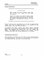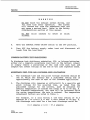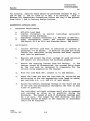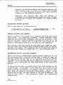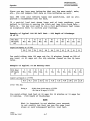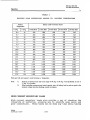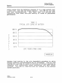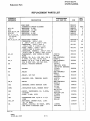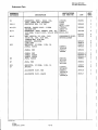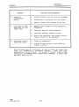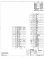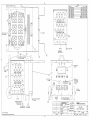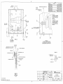
1
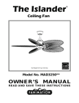
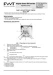
~ SBS
Storage Battery
Systems, Inc.
Since 1915
SBS MODEL BCT-SOOO
LOAD BANK (DC RESISTIVE)
Part Number K492D26649
150A @ 21/42/105 VDC
171 A @ 24/481120 VDC
16 October 1996
Rev. 15 July 1997
SBS MODEL BCT-SOOO
LOAD BANK (DC RESISTIVE)
Part Number K492D26649
TABLE OF CONTENTS
section I
SAFETY CONSIDERATIONS
· 1-1
section II
DESCRIPTION
· 2-1
section III
INSTALLATION . .
· 3-1
section IV
OPERATION
• 4-1
section V
MAINTENANCE
· 5-1
section VI
REPLACEMENT PARTS LIST .
· 6-1
APPENDIX
Load Bank Troubleshooting Guide
DRAWINGS
SB2615
Load Bank (Outline Drawing)
C23218
Schematic/Interconnection, Load Bank
K492D26649
Load Bank
DTB/kv
10/16/96
-i-
SBS MODEL BCT-5000
LOAD BANK (DC RESISTIVE)
Part Number K492D26649
SECTION I
SAFETY CONSIDERATIONS
Throughout this manual, you will find WARNING and CAUTION
statements. Personal injury to an operator using or repairing the
equipment may occur if a WARNING statement is ignored. Damage to
the equipment and potentially hazardous conditions for personnel
may occur if a CAUTION statement is ignored.
Each unit is safety checked for opens and shorts, and the
insulation is high potential tested to insure safe operation. All
safety devices have been proven reliable as part of the testing
procedure of each unit.
As part of your safety program, an initial inspection after
receiving the unit(s) and periodic preventive maintenance and
safety inspections should be conducted to insure the reliability
and safety built into your Load Bank.
The Model BCT-5000 Load Bank is an industrial test unit designed to
be used indoors.
However, because the nature of the Load Bank
function is the dissipation of electrical energy, there are
inherent dangers to the operator and to the equipment.
These
dangers shall be outlined in this section.
Electrical energy is transformed into heat by the resistor
elements.
The heat is removed from the Load Bank by airflow
through the resistor elements. . If there are any restrictions or
stoppage of .airflow, the Load Bank may overheat and may even start
a fire. The following recommendations are made:
1.
Read the manual before operating the Load Bank.
2.
Run an approved ground wire from the Load Bank ground terminal
(GND) , located on the lower right side of the control panel.,
to the battery supply under test. Run an approved ground wire
from the supply under test frame to a good earth ground. Size
ground wire in accordance with National Electrical Code and
any local codes.
3.
Do not bypass OVER TEMP SAFETY switches to prevent nuisance
tripping. The switches will drop out the load if insufficient
cooling air is reaching the elements.
DTB/kv
10116/96
1-1
SBS Model BCf-5000
Load Bank (DC Resistive)
Part Number K492D26649
Safety Considerations
4.
The Load Bank is not internally protected from short circuit
faults or overcurrent applications.
Therefore, it is
recommended that the battery supply being tested contain a
fuse or that an external fuse be added between the battery
supply and the Load Bank input terminals.
5.
Replace the lights on the control panel if they are burned
out.
The lights serve as indicators that the Load Bank is
overheating, that reverse polarity is connected at input
terminals, or that an over or under voltage condition and/or
control power is present. This is important to the operation
of the unit and the safety of the operator.
**************************************************
WARNING
Personal injury from electrical shock may
result if power is not disconnected before
servicing. Maintenance work must be done only
by qualified personnel.
**************************************************
6.
Maintenance should be performed with no power on the unit.
The majority of troubleshooting can be performed with an
ohmmeter.
7.
venting the heated air from the exhaust toward overhead
cables, sprinkler systems, or into a room with insufficient
volume or make-up air, is a potential hazard. The Load Bank
should be used in a cool, well-ventilated area.
8.
Allow cool room air to pass into the uni t to cool the
elements.
Do not allow the unit to be placed where hot
exhaust air can recirculate back through the unit causing a
constant rise in cooling air temperature.
9.
After running a load test, residual heat may be removed from
the Load Bank by allowing the blower to operate for a few
minutes after load is removed. This procedure is not required
for maintaining Load Bank' integrity, but it may guard
operating "personnel from possible burn· injuries.
10.
The operator should avoid coming in contact with the resistor
elements or surrounding covers during and for some time after
operation. These portions of the Load Bank become quite hot
and may result in a serious burn should contact be made with
them.
DTB/kv
10/16/96
1-2
SBS Model BCT-5000
Load Bank O)C Resistive)
Part Number K492D26649
Safety Considerations
11.
Do not allow objects to enter or block the air intake or
exhaust of the Load Bank. A blockage would cause Load Bank
overheating. If an object enters the screens, it will cause
damage to the resistor elements, possibly shorting them and
causing shock and fire hazards.
12.
Emergency Shutdown Procedure:
In an emergency, disconnect the load and fans using the
CONTROL POWER ON/OFF switch; then deactivate the battery
source under test.
The CONTROL POWER ON/OFF switch will disconnect both the load
steps and the fans.
13.
An approved electrical fire extinguisher should be on hand at
all times.
14.
It is the responsibility of the customer to take diligent care
in operating the Load Bank.
The National Electrical Code
(NEC) , sound local electrical and safety codes, and the
Occupational Safety and Health Act (OSHA) should be followed
when installing the equipment to reduce hazards to persons and
property.
15.
Observe proper polarity when connecting the Load Bank to the
battery source. If the Load Bank is not connected properly,
the meter will not monitor the load.
16.
The Load Bank should never be left unattended while it is
operating.
17.
Read and heed all WARNING and CAUTION statements
manual.
DTB/kv
10116/96
1-3
in the
SBS Model BCf-5000
Load Bank (DC Resistive)
Part Number K492D26649
SECTION II
DESCRIPTION
The Model BCT-5000 Load Bank is an indoor" portable, self-contained
unit designed for electrically loading and testing 24/48/120 VDC
The Load Bank is designed for production line
battery supplies.
and job site use.
The loading capability at 21/42/105 VDC consists of six steps for
a total of 150 Amps. They are:
5, 10, 10, 25, 50, and 50 Amps.
When applying nominal voltages 24/48/120 VDC, the total load
increases to 171A with load steps 5.7, 11.4, 11.4, 28.5, 57.1, and
57.1 amps.
**************************************************
C AUT ION
DO NOT operate the Load Bank at voltages
greater than 20% the rated voltage as this
will cause a catastrophic failure in the Load
Bank.
**************************************************
CONTROL PANEL
Load application is controlled from the integral mounted control
panel at the front of the Load Bank. Controls and indicators are
located on the Load Bank control panel as follows.
1.
The CONTROL POWER ON/OFF switch controls power to the unit,
power to load steps, and fan power.
2.
The MASTER LOAD switch controls power to the load steps. The
MASTER LOAD switch will also reset Load Bank controls after an
over/unde~ voltage condi"tion.
3.
The OVER TEMP indicator lamp lights if the Load Bank
overheats. This lamp lights momentarily when power is turned
on, but goes off when the safety circuit is cleared.
DTB/kv
10116/96, Rev. 213/97
2-1
SBS Model BCf-5000
Load Bank Ene Resistive)
Part Number K492D26649
Description
4.
The CONTROL POWER indicator lamp energizes when voltage is
applied to the 120V receptacle and the CONTROL POWER switch is
ON.
5.
The OVER/UNDER VOLTS indicator lamp energizes when voltages
greater than 28V or less than 18 volts is applied to the Load
Bank 24 VDC input terminals.
For the 48 VDC terminals, the
limits are 56V and 36V. For the 120 VDC terminals, the limits
are 140V and 90V.
Note that these limit values may vary as
much as 5%.
6.
The load step ON/OFF switches are used to apply or remove load
steps at the ratings listed above each switch.
7.
The digital meter monitors the load applied. Meter monitoring
banana style plug terminals are located on the control panel
of the Load Bank. This allows for remote meter monitoring at
the source being tested. Voltage, current, elapsed time, and
amp-hours are units monitored to an accuracy of ±1% of full
scale.
Full scale of volts and elapsed time is 199.
Full
scale of current and amp-hours is 1999.
Note that the DC voltages that are not pure DC may not give
accurate data.
The meter monitors volts and amps with an
averaging computation method.
ENCLOSURE
The Load Bank is shown on Outline Drawing SB2615 and is 22 inches
high, 25 inches deep, and 22 inches wide. The screened air intake
is located on one side of the unit, and exhaust is discharged
outward through the opposite side screened opening.
DTB/kv
10/16/96, Rev. 213/97
2-2
SBS Model BCI'-5000
Load Bank (DC Resistive)
Part Number K492D26649
Description
POWER CONNECTIONS
**************************************************
C AUT ION
Never exceed the rated voltage by more than
20%
as this will cause the Load Bank
to overheat.
Failure to connect the battery supply under
test to the correct polarity on the Load Bank
will prevent meter from functioning. Refer to
the Safety Considerations section of this
manual.
**************************************************
Control and fan power requirements are 120 VAC at approximately
5 Amps. This power is accepted through the 120V receptacle on the
control panel. Use line cord PIN 390874.
To connect load power, attach load cables (B25464 supplied
separately) to the input power~terminals on the front of the Load
Bank.
The terminals are labeled 120V, 48V, 24V, COMMON, and
GROUND.
The COMMON terminal 'is common to all voltages.
Use the
terminals that match the voltage application to be tested.
WHEELIHANDLE/CORDRACK
The Load Bank is provided with rear wheels and an extended handle
for easy portability. The handle is also convenient for storage of
load cables when the Load Bank is not being used.
DTB/kv
10116/96, Rev. 3/7/97
2-3
SBS Model BCT-5000
Load Bank CDC Resistive)
Part Number K492D26649
SECTION III
INSTALLATION
BEFORE INSTALLATION
Inspect the Load Bank for obvious damage such as broken wires,
broken or dented panels, cracked ceramic insulators, or any other
component breakage that may have occurred in shipment.
LOCATION
The BCT-5000 is a portable, indoor Load Bank, and should be
installed in a cool, well-ventilated area.
Cool air must be
continually available so the hot exhaust air can be dissipated
and not recirculated through the unit. Install such that the inlet
and exhaust panels have unrestricted airflow clearance.
**************************************************
CAUTION
Installation must prevent hot exhaust air from
recirculating into the air intake. Inlet air
temperatures exceeding 104°F may cause damage
to the Load Bank.
After installation, test
the unit at full load and verify that the
inlet air temperature does not exceed 104°F.
**************************************************
AIRFLOW CONSIDERATIONS
Even with an ample supply of cooling air, the Load Bank may
overheat if it is not properly installed. There are two types of
airflow problems that should be avoided:
1.
Recirculating Airflow - If the hot, exhausted air is permitted
to recirculate through the Load Bank, it will reach such a
high temperature and low density that it will no longer cool
the resistance elements. A Load Bank should not be installed
so close to any surface as to reflect the exhausted air back
DTB/k:v
10116/96, Rev. 317197
3-1
SBS Model BeT-SOOO
Load Bank ~C Resistive)
Part Number K492D26649
Installation
to the air intake.
When two or more Load Banks are being
used, care must be taken in positioning the Load Banks so that
the exhausted air of one unit does not feed the air intake of
another.
2.
Restriction of Cooling Air - Any obstruction located within
two (2) feet of the inlet and exhaust screens will restrict
the Load Bank's airflow. Airflow is also restricted when two
or more Load Banks have air inlets positioned close to each
other. This competition for cooling air causes a low pressure
area, restricting adequate airflow.
**************************************************
WARNING
It is vitally important to install the Load
Bank properly. Installation errors may result
in a catastrophic failure.
The temperature
switches,
and protective devices in the
Load Bank, will guard against some of these
problems.
If protective circuitry prevents
application of the load, determine the source
of
the
problem.
DO NOT
DISABLE the
TEMPERATURE SWITCHES.
This causes a safety
hazard and voids the warranty. The following
installation instructions are critical to the
safe operation of the Load Bank. Refer to the
Safety Considerations section of this manual.
**************************************************
POWER REQUIREMENTS
The Load Bank derives its control/fan power from the control power
receptacle on the Load Bank control panel.
Use line cord P /N
390874. Control and fan power is derived at 120 VAC, approximately
5 Amps.
The battery supply under test load ·connections are at the terminal·s
mounted on the·. control panel.
The terminals are identified as
120 Volts, 48 Volts, 24 Volts, and COMMON. Cables (B25464-1 and -2
supplied separately) are to be connected to the respective load
terminals as required for the voltage rating of the supply to be
tested. The COMMON terminal is common to all voltages.
DTB/kv
10/16/96, Rev. 317197
3-2
SBS Model BCT-5000
Load Bank: EDC Resistive)
Part Number K492D26649
Installation
***************************************************
CAUTION
The Load Bank is not internally protected from
short
circui t
faul ts
or
overcurrent
applications.
Therefore, it is recommended
that the battery supply being tested contain a
fuse or that an external fuse be added between
the battery supply and the Load Bank input
terminals.
***************************************************
Cables to the Load Bank should be of adequate size to handle
maximum rated load according to the National Electrical Code and
any local codes.
A case ground terminal is provided on the lower right side of the
control panel and must be connected to the battery under test
frame, which in turn should be connected to a good earth ground.
Use cable PIN B25464-3 for this connection.
DTB/kv
10/16/96, Rev. 317197
3-3
SBS Model BeT-SOOO
Load Bank (DC Resistive)
Part Number K492D26649
SECTION IV
OPERATION
PURPOSE AND USE OF CONTROLS
1.
CONTROL POWER ON/OFF switch - This switch turns on the cooling
fans and powers the remainder of the control circuit.
2.
OVER TEMP lamp - This lamp should momentarily light when
MASTER LOAD switch is turned on.
This shows the air safety
circuit is working. The purpose of the OVER TEMP lamp is to
warn the operator and remove the load to the Load Bank in case
of improper cooling of the load elements.
3.
Load step ON/OFF switches - Allow load steps to be applied or
removed at the rating identified under each switch.
4.
The MASTER LOAD switch controls power to the load steps. The
MASTER LOAD switch will also reset Load Bank controls after an
OVER/UNDER voltage condition.
5.
The OVER/UNDERc.VOLTS indicator lamp energizes when voltages
greater than 28V or less than 18 volts is applied to the Load
Bank 24 VDC input terminals.
For- the 48 VDC terminals, the
limits are 56V and 36V. For the 120 VDC terminals, the limits
are 140V and 90V.
Note that these limit values may vary as
much as 5%.
6.
The digital meter monitors the load applied. Meter monitoring
banana style plug terminals are located on the control panel
of the Load Bank. This allows for remote meter monitoring at
the source being tested. Voltage, current, elapsed time, and
amp-hours are units monitored to an accuracy of ±1% of full
scale.
Full scale of volts and elapSed time is 199.
Full
scale of current and amp-hours is 1999.
Note that DC voltages that are not pure DC may not give
accurate data.
The meter monitors volts and amps with- an
averaging computation method.
DTB/kv
10116/96, Rev. 2/3197
4-1
SBS Model BCT-5000
Load Bank: ~C Resistive)
Part Number K492D26649
Operation
LOAD BANK OPERATION
All tests start with control panel switches in the OFF position.
**************************************************
C AUT ION
Before energizing any load, verify that load
voltage does not exceed rated voltage of Load
Bank by more than 20%.
**************************************************
The unit is energized by the CONTROL POWER ON/OFF switch.
This
switch also energizes the cooling fans. Upon energizing the unit,
the red OVER TEMP lamp will light momentarily until the enclosed
temperature switches signal that safe operating temperature is
present, at which time the light goes off.
The load steps are
enabled by energizing the MASTER LOAD switch. If Load Bank voltage
applied to the power terminals is between the volt sensor settings,
activating the appropriate load switches will apply the load to the
battery supply under test.
If not, the MASTER LOAD switch will
have to be reset by toggling on and off while voltage applied is
within volt sensor settings.
If the operating temperature in the Load Bank reaches an unsafe
level, the temperature switches disconnect the load and the red
OVER TEMP lamp will light.
**************************************************
C AUT ION
Do not attempt operation if the fans are not
running.
Fan inlet and exhaust must be
unrestricted.
The operation of the fan is
vi tal to the safe operation of this Load
Bank. If the OVER TEMP indicator light comes
on and stays on for more than a few seconds
without the load dropping out, shut off the
MASTER LOAD switch .at once. Remove all power
to the unit and check for proper operation of
the fan safety circuit. Failure to correct an
over temperature condition will result in the
destruction of the Load Bank.
Refer to the
Safety Considerations section of this manual.
**************************************************
DTB/kv
10/16/96, Rev. 213/97
4-2
SBS Model BCf-5000
Load Bank: (DC Resistive)
Part Number K492D26649
Operation
OPERATING INSTRUCTIONS
**************************************************
C AUT ION
Never exceed the rated voltage by more than
20% as this will cause the Load Bank to
overheat.
Failure to connect the battery source to the
correct polarity on the Load Bank will prevent
meter from functioning.
Refer to the Safety
Considerations section of this manual.
**************************************************
1.
with all control panel switches in the OFF position, connect
the 120V line cord and the appropriate battery supply leads to
the Load Bank.
2.
Connect cable from Load Bank ground terminal to battery supply
under test frame.
3.
Connect battery supply- under test
ground.
4.
Activate battery supply under test.
5.
Move the CONTROL POWER switch to the ON position. Verify that
the red OVER TEMP lamp momentarily lights and then goes off.
6.
Enable the LOAD STEP switches by moving the MASTER LOAD switch
to the ON position. Activate the desired load using control
panel load switches.
7.
After running tests, remove the load by moving the MASTER LOAD
ON/OFF switch to the OFF position.
Accumulated heat may be
removed from the Load Bank by allowing the cooling fans to
operate for a few minutes with load removed. This procedure
is not required for maintaining Load Bank integrity, but it
may guard operating pers_onnel from possible burn injuries . .
DTB/Iev
10/16/96, Rev. 317197
4-3
frame
to a
good
earth
SBS Model BCT-5000
Load Bank ~C Resistive)
Part Number K492D26649
Operation
**************************************************
WARNING
DO NOT touch the exhaust screen during, and
for some time after operation.
The screen
will become hot from the exhausted heat and
may cause a serious burn. Refer to the Safety
Considerations section of this manual.
DO NOT allow
screens.
objects
to
enter
or
block
**************************************************
8.
Move the CONTROL POWER ON/OFF switch to the OFF position.
9.
Turn OFF the battery supply under test and disconnect all
leads from the Load Bank.
COMMON BATTERY TEST PROCEDURES
To discharge test stationary substation, :ups, or telecom batteries,
either run a complete acceptance load test on the battery (ideal)
or simply remove a percentage' of the load with each test and
compare the lowest voltage at the end of the like repeated tests.
ACCEPTANCE TEST TIME AND DISCHARGE RATE CALCULATION
1.
The discharge time and end point voltage selected should be
one at which the battery has a published rating and is
approximately the same as that of the intended application.
2.
The discharge rate (amperes or watts/cell) to a specific end
point voltage for the selected time, as taken from the
published ratings for the battery, must be adjusted for
battery temperature if outside the range of 75 to 80 deg .. F.
For elevated temperatures, the rate will be increased while
for cooler temperatures, ,the rate is reduced. The temperatur'e
adjustment factors are noted in Table 1.
For example, if a cell having a one hour rating of 61.5
amperes to 1.75 V/cell @ 77 deg. F were tested at 60 deg. F,
the discharge rate used for a one hour discharge would be:
61.5 amperes x 0.93 - 57.2 amperes
DTB/kv
10116/96, Rev. 5112/97
4-4
SBS Model BCf-5000
Load Bank <pC Resistive)
Part Number K492D26649
Operation
For accuracy, capacity tests should be performed between 60 deg. F
and 90 deg. F, and as close to 77 deg. F as possible.
This is
because the temperature corrections factor can vary a few percent
from Table 1 due to battery design factors.
ACCEPTANCE CAPACITY TEST
1.
Equipment Requirements
a.
b.
c.
d.
2.
BCT-5000 Load Bank
Digital Voltmeter: to monitor individual cells/unit
voltage during discharge.
Hydrometer (digital Preferred; e.e. SBS-2002 or SBS-1001.
other Nonessential Items: Non Contact Thermometer,
SBS/Raytek ST-2 or ST-6 and MicroOhm Meter, SBS #5600.
Performance
a.
Connect BCT-5000 Load Bank to batteries as covered in
paragraph 4-2 of manual. If parallel strings are being
tested, the individual string current and total current
must both be monitored.
b.
Measure and record the float voltage of each cell/unit
and assure all cells/units are floating properly.
c.
Remove the charging current from the battery.
If the
charger cannot be disconnected, the current being drawn
by the load must be increased to compensate for the
current being supplied by the charger.
d.
with the Load Bank OFF, connect it to the battery.
e.
Reset the timer and turn the load bank ON, adjusting and
maintaining it for the appropriate rate (amps or watts)
per sections 4-2, 4-3, and 4-4 of user manual.
f.
Record the battery discharge voltage at the start and end
of the test and periodically throughout the test as many
times as practical.
The individual cell/unit. voltages shall also be measured
and recorded as often as is practical during the
discharge. The number of sets of discharge readings must
be 3 or more.
The longer the test duration, the more
readings should be taken so the capacity of individual
cells can be analyzed.
DTB/kv
5112/97, Rev. 7/15197
4-5
SBS Model BCf-5000
Load Bank (DC Resistive)
Part Number K492D26649
Operation
continue the discharge beyond the required battery end
point voltage (e.g., 1.85 VIC) to a lower rated voltage
(e.g. 1.75) when possible to assure most cells actually
discharge to the required end point.
Terminate the capacity test when the battery is
discharged to the predetermined system end point voltage,
a cell or unit is going into reversal, or a safety hazard
is noted.
CALCULATING BATTERY CAPACITY
The % rated capacity is calculated as:
Actual Discharge Time
Specified Discharge Time
% rated capacity @ 77 deg. F
To specified end point voltage
x
100%
PARTIAL CAPACITY LOAD TESTING
Partial capacity load testing is an approved method of performing
load tests.
By comparing discharge voltage readings under
identical test conditions, meaningful data can be collected. This
test can be done, normally without removing more than 50% of the
battery capacity, leaving 50% to handle the load should the AC
power be interrupted soon after the test has been completed.
This partial load test should be done about four times per year.
The test takes less than one hour to perform and no back up (spare)
batteries are needed.. The comparison data is reliable test data on
the batteries' condition, second only to a full discharge test.
RECOMMENDED PARTIAL LOAD TEST CURRENTS
Look at the battery manufacturer's ampere current capability to 1.75
VPC (volts per cell). Find the current that is below 150 amps and
use that current for the test; i.e., if battery is rated to deliver
150 amperes for one hour, test at 150 amps for 50% of one hour (30
minutes). Do not be concerned about maintaining exactly 150 amps;
just be sure to always have the same load switch on for exactly 30
minutes.
At the end of t~e test, you should record the lowest voltage at the
30 minute mark. If you want to test each cell, do so after the 30
minute voltage is recorded.
Be sure to time each test the same
when doing the same battery on subsequent tests.
You will still
have about 50% capacity remaining in the battery system.
If any
battery has failed, you must replace it as soon as possible.
Be
sure to use Table 1 load correction tables for temperature
compensation.
DTB/kv
5112/97, Rev. 7/15197
4-6
SBS Model Bcr-5000
Load Bank (DC Resistive)
Part Number K492D26649
Operation
since you may have many batteries that are the same model, make,
etc., you can compare test data on like batteries as well.
Call SBS with your battery types and quanti ties,
provide a recommended test for each.
and we will
If a partial load test shows lower end of test readings, your
battery is failing or nearing its life's end (see Life Curve Data Table 2). You may also want to run a f~ll performance test (same
as acceptance test) to confirm your findings.
Example of Typical 200 AH Cell Test - 50% Depth of Discharge
(D of D)
8 Hr. Rated
AH Capacity
200
5
Min.
1
Min.
Ph
10
Min.
15
Min.
20
Min.
30
Min.
1
Hr.
Hrs.
3
Hrs.
5
Hrs.
8
Hrs.
234
210
190
154
100
80
50
34
25
Ampere Load Capacity to 1.75 VPC
I
296
I
268
I
You could either take 100 amps out for 30 minutes (based on 50% of
one hour) or 80 amps out for 45~ minutes (based on the 1~ hour
rate).
Example of Typical 24 AH Battery Test
8 Hr. Rated
AH Capacity
24
5
Min.
10
Min.
15
Min.
30
Min.
1
Hr.
2
Hrs.
3
Hrs.
5
Hrs.
6
Hrs.
8
Hrs.
10
Hrs.
32.5
20.5
13.3
8.25
6.25
4.00
3.50
2.75
2.35
Ampere Load Capacity to 1.75 VPC
I
56.5
I
41.3
I
24 AH - 8 Hr. Rate
Having a:
30 Min. Rate of 20.5 amps to 1.75 VPC
1 Hr. Rate of 13 amps ~o 1.75 VPC
You could either load test at 20 amps for 15 minutes or 13 amps for
30 minutes.
(50% Depth of Discharge)
What is important is not whether your current
is set exactly but that you use the same load
steps on each subsequent partial load test.
DTB/kv
5112/97, Rev. 7/15197
4-7
SBS Model BCf-5000
Load Bank (PC Resistive)
Part Number K492D26649
Operation
TABLE 1
BATTERY LOAD CORRECTION FACTOR VS. BATTERY TEMPERATURE
Battery
Temperature
CDeg.
I
FDeg.
Battery Load Correction Factor
15 Min Rate 11 Hour Rate 15 Hour Rate
Is
Hour Rate
I
20 Hour Rate
-9.4
15
.550
.580
.650
.705
.735
-6.7
20
.660
.630
.690
.735
.765
-3.9
25
.650
.680
.735
.765
.790
-1.1
30
.700
.725
.765
.790
.815
1.7
35
.740
.765
.800
.820
.840
4.4
40
.780
.800
.830
.845
.865
7.2
45
.820
.840
.855
.870
.890
10.0
50
.860
.865
.880
.895
.910
12.8
55
.875
.890
.910
.920
.930
15.6
60
.920
.930
.940
.945
.950
18.3
65
.940
.950
.955
.960
.965
21.1
70
.960
.970
.975
.978
.980
25.0
77
1.00
1.000
1.000
1.000
1.000
26.7
80
1.010
1.005
1.003
1.002
1.001
29.4
85
1.030
1.020
1.015
1.010
1.005
32.2
90
1.040
.1.025
1.020
1.015
1.010
35.0
95
1.050
1.030
1.025
1.020
1.015
37.8
100
1.060
1.040
1.030
1.025
1.020
Watts per Cell and Ampere's Load Derating vs. Temperature
Note:
1)
2)
Perform acceptance tests only in the range of 60 deg. to 90 deg. F and preferably as near to
77 deg. F as possible.
When conducting constant power (watts) capacity tests, the battery load in watts is equal to the
terminal voltage times the discharge current in amperes.
IDGH CURRENT MOMENTARY LOADS
High current momentary loads also provide a way of checking the
integrity of batteries, allowing you to identify weak cells and
poor connections.
These tests can be done any time while taking
DTB/kv
5112/97, Rev. 7115197
4-8
SBS Model BCf-5000
Load Bank (pC Resistive)
Part Number K492D26649
Operation
little energy from the batteries (because it is a high current over
a short time, less than one minute typical). Call SBS for our high
rate test recommendations.
This short test will provide more
information than other non-load testing in terms of guaranteed
performance.
TABLE 2
TYPICAL LIFE CURVE OF BATTERY
100 % /
80 %
C
A
60 %
P
40 %
A
C
I
T
~
""
20 %
0 %
Y
LIFE YEARS (TIME LINE)
D6648D1LAN
Battery Load testing is the only dependable procedure by which
battery condition and performance can be determined. Lack of load
testing has resulted in losses of millions of dollars reported by
companies wi th" substations, power generating, and data center
failures.
Call SBS at 1-800-554-2243 for answers to any battery
system questions.
DTB/kv
5/12/97, Rev. 7/15197
4-9
ESD PRECAUTIONARY GUIDELINES
C AUT ION
Certain circuit card assemblies and their
components, typically integrated circuits, may
be
damaged
by
seemingly
undetectable
electrostatic discharge (ESD).
Care must be
exercised during handling/repair of these
items.
Use
electrostatic
discharge
precautionary procedures.
The following guidelines are not necessarily all inclusive but
rather serve as reminders for good shop practices for the handling/
repair of ESD sensitive circuit card assemblies and devices.
Store ESD sensitive items in their original containers.
These items are often marked with the symbol shown at the
top of this page.
Put on a grounded wrist strap before handling any ESD
sensitive item.
Clear work area of Styrofoam®*, plastic, and vinyl items
such as coffee cups.
Handle ESD
connectors.
i terns
by
the
body,
never
the
open
edge
Never slide ESD sensitive items over any surface.
Transport ESD sensitive items in a static
container to a static-free work station.
shielding
If a static-free work station is not available, ground
the transport container before removing or inserting an
ESD item.
Electric tools used during repair should be grounded.
For example, use only anti-static type solder suckers and
grounded tip soldering irons.
Discharge non-electric
tools before use.
Pack ESD i terns in static shielding containers before
shipping them to Avtron for repair.
* Styrofoam® is a registered trademark of Dow Chemical.
SBS Model BCT-5000
Load Bank: QJC Resistive)
Part Number K492D26649
SECTION V
MAINTENANCE
To provide long equipment life and to redpce the chance of electric
shock, fires, and personal injury, good maintenance procedures must
be used.
Before servicing, review the Safety Considerations
section of this manual.
The following examples of scheduled maintenance procedures are not
intended to be all-inclusive, but must be accomplished to maintain
the equipment in a good, safe condition. All maintenance work must
be done only by qualified personnel.
*******************************************************
WARNING
Personal injury from electrical shock or from
the moving fan blades may result if power is
not disconnected from the Load Bank prior to
performing maintenance procedures.
Refer to
the Safety Considerations section of this
manual.
*******************************************************
DAILY
1.
Remove any restrictions to airflow through the Load Bank.
2.
Check the screens to make sure that no objects have blocked or
entered the openings.
3.
Verify that the airflow is in the proper direction.
4.
Assure that there is no recirculation of the exhaust air
through tqe Load Bank.
DTB/kv
10/16/96
5-1
SBS Model BCf-5000
Load Bank Ene Resistive)
Part Number K492D26649
Maintenance
THREE MONTHS OR 500 HOURS
1.
Remove access panels and screens.
2.
Inspect the load resistors for mechanical breakdown which is
demonstrated by excessive sagging of the elements.
Replace
with new resistor elements as required.
I
3.
Inspect for loose hardware or loose connections.
where required.
Tighten
I
4.
Inspect all connections for oxidation or corrosion.
connection or replace the hardware where required.
Clean the
5.
Inspect magnetic contactors to make sure that the contacts are
not severely pitted or corroded.
The contacts must move
freely and be properly seated.
6.
Clean all dirt and debris out of the Load Bank. This can be
accomplished by blowing the inside of the unit with clean, dry
compressed air (not to exceed 40 PSI). Eye protection should
be worn when cleaning the Load Bank with compressed air.
7.
Inspect all the wiring for any sign of insulation failure.
8.
Replace all access panels and screens.
fastening hardware securely.
9.
Check the indicator lamp on the control panel.
Tighten all
the
PARTS REPLACEMENT
Access to any component is easily made with the removal of the
cover panels.
Maj or components in the unit are listed in the
replacement parts list.
DTB/kv
10116/96
5-2
SBS Model BCf-5000
Load Bank: gJC Resistive)
Part Number K492D26649
SECTION VI
REPLACEMENT PARTS LIST
INTRODUCTION
The parts list in this section contains the description, quantity
required, and part numbers for each listed part.
The list also
includes, where appropriate, the manufacturer's part number and
federal code number, as well as schematic reference designators to
facilitate troubleshooting.
Every effort has been made to insure the
accuracy of this information.
However,
changes are sometimes necessary and revisions
to the parts list may be made at any time
without notice.
REFERENCE DESIGNATORS
service personnel may use this parts list along with the system
schematics to identify and order replaceable parts. The reference
designators were carefully selected and matched to those on the
schematic diagrams and equipment to simplify the troubleshooting
and repair process.
When ordering replacement parts, be certain to
state the part's description and part number,
not the schematic reference designator number.
Also include the model and serial number of
the equipment.
MANUFACTURERS' FEDERAL CODE NUMBERS
The manufacturer and part number column contains, in parentheses,
the Commercial and Government Entity code number (CAGE code), a
five character string listed in H4-1/H4-2.
This CAGE code
identifies the manufacturer of the listed part. The following is
a numerical cross-reference listing of CAGE codes to manufacturers'
names and addresses.
DTB/kv
10/16/96
6-1
SBS Model BCf-5000
Load Bank (DC Resistive)
Part Number K492D26649
Replacement Parts
FEDERAL CODE NUMBER LIST
03030 Empro Mfg. Co. Inc.
10920 E. 59th st.
P.O. Box 26060
Indianapolis, IN 46226
63681 Crouzet Corp.
(Formerly Syrelec corp.)
3237 Commander Dr.
Carrollton, TX
75006-2503
06352 Empire Products Inc.
CAM-LOK Div.
Subdivision of KDI Corp.
Cincinnati, OR
71400 Cooper Industries Inc.
Bussmann Div.
114 Old State Rd.
Ballwin, MO 63021-5942
12066 Ohio Semitronics, Inc.
4242 Reynolds Dr.
Hilliard, OH 43026-1260
71785 TRW Cinch Conn'ectors
1501 Morse Ave.
Elk Grove Village,
IL 60007
15605 Eaton corporation
Administrative &
Technical Center
4201 N. 27th st.
Milwaukee, WI 53216
73559 Carlingswitch Inc.
60 Johnson Ave.
Plainville, CT
06062-1156
16428 Cooper Industries
Belden Division
350 N.W. N st.
Richmond, IN 47374
77342 Potter & Brumfield Inc.
200 S. Richland Creek
Dr.
Princeton, IN
47671-0001
5S447 Test Probes Inc.
LaJolla, CA 92037
82807 Milwaukee Resistor Corp.
8920 W. Heather Ave.
P.O. Box 24200
Milwaukee, WI 53224-0200
51107 Diversified Electronics
320 E. Main st.
P.O. Box 207
Leesburg, FL 34748-0207
72619 REPLACED BY:
83330 Dialight Corp.
Manasquan Div.
1913 Atlantic Ave.
Manasquan, NJ 08736~1005
59270 Selco Products Inc.
7580 Stage Rd.
Buena Park, CA
90621-1224
63279 Weidmuller Terminations.
821 Southlake Blvd.
Richmond, VA 23236-3917
DTB/kv
10116/96, Rev. 317197
6-2
SBS Model BCf-5000
Load Bank (DC Resistive)
Part Number K492D26649
Replacement Parts
REPLACEMENT PARTS LIST
SCHEMATIC
REFERENCE
MANUFACTURER
and PART NO.
DESCRIPTION
D26649
C23218
AWR400
AWR12 00
AWR200
AWR600
A23368-1
LOAD BANK
.SCHEMATIC/INTCON DIAGRAM
• RESISTOR, 4 OHM
• RESISTOR, 12 OHM
• RESISTOR, 2 OHM
• RESISTOR, 6 OHM
.RESISTANCE ELEMENT
R31,32
R33
R34,35,37,38
R36,39
R4,5,7,8,10,
11,13,14,
16,17
R6,9,12,15,18 .RESISTANCE ELEMENT
• INSULATOR, .500+/-.005
X .385+/-.005 X .530+/-.006
• INSULATOR, .370+/-.005 X
.195+/-.005 X 1.195+/-.012
.TUBE, INSUL; .530+/-.005 X
.330+/-.005 X 2.00+/-01
• INSULATOR, CERAMIC; .500+/-.005 X
.375+/-.005 X .625+/-.010, S-151
• THERMOSTAT: 300F OPENS ON TEMP
S9,10
RISE
• RELAY; 3P, N.O., 600 VAC, 35A @
K1
0.05PF, 120 VAC, 60 HZ COIL
• RELAY; 3P N.O., 65A @ 600V RES,
K2,3
52A @ 600V IND, 120 VAC COIL
• RELAY, VOLTAGE SENSING
K4
XK4
• SOCKET
K7
• RELAY
K6
• RELAY, 120 VAC
• BRACKET, END, TERMINAL BLOCK
K8,9
• RELAY
TB1
.TERMINAL BOARD BARRIER TYPE
XTB1
.INSULATION ELEC, MARKER STRIP
R20
• SHUNT, INSTRUMENT;
0-100MV
.FUSE, 5 AMP, 600V
F1
XF1
R21,24
M1
Form No.
DC~
0-20'OA,
.FUSEHOLDER FOR 13/32 X 1-1/2
FUSE
• RESISTOR, CARBON FILM, 1/2W,
1%, 10 KOHM
• METER, DIGITAL; DC VOLTS, AMPS,
AMP HOUR & ELAPSED TIME
m
DTB/kv
10/16/96, Rev. 213/97
6-3
PIN
(59270)
OA-300
ABB CONTROLS
B30DC-1
ABB CONTROLS
B50DC-1
(51107 )
VBA-1201 WITH
100-54-80 BRACKET
(77342 )
27E123
ABB CONTROLS
B9DC-1
(77342 )
KUP14A55-120
(63279)
3835.6
ABB CONTROLS
B12DC-1
(71785)
10-141
(71785)
MS-10-141
(03030)
MLB""'!'200-100
(71400)
KTK-R-5
(71400)
HPS-RR
(12066)
PTP-4605
QTY/
UNIT
REF •
2
1
4
2
10
A23368-2
411182
60
411181
30
411141
105
411145
15
491012
2
351891
1
350350
2
350675
1
358206
1
351889
1
351170
1
364433
2
350830
2
364072
1
450087
1
337995
1
324211
1
324985
1
123037
2
338159
1
5
SBS Model BeT-5000
Load Bank (DC Resistive)
Part Number K492D26649
Replacement Parts
SCHEMATIC
REFERENCE
P1
DSl-3
Sl-6,8
El-5
Bl-6
R22
E6
E7
R21
S7
MANUFACTURER
and PART NO.
DESCRIPTION
(16428)
17252
IMLEC
NR151-110R
(73559 )
• SWITCH, TOGGLE DPST, 4 TERM
2GK50-73
ON-NONE-OFF
(06352)
• CONNECTOR, RECP; FEMALE, BLK, #23/0 WIRE, 315A @ 120V, 3/8-16 STUI E1012-333
• FEET
SUNONWEALTH ELEC.
.FAN, MUFFIN; 115 CFM, 115V,
SP100A1123XST
50/60 HZ, 20W, 3100 RPM,
SLEEVE BRG, PIN CON
• BRACKET, RESISTOR
.LINE CORD
.RESISTOR, 30 KOHM, 1/2W, 5%
(5S447)
• CABLE, BLACK
123501B
(5S447)
• CABLE, RED
12501R
• CABLE, RED
• CABLE, BLACK
• CABLE, GREEN
(83330)
• PLUG, BLACK
257-103
(83330)
• PLUG, RED
257-102
• RESISTOR, 10 KOHM, 1/2W, 1%
(15605)
• SWITCH
8373K107
(5S447)
.ALLIGATOR CLIP, RED
126000/R
(5S447)
.ALLIGATOR CLIP, BLACK
126000/B
• CONNECTOR, RECP., MALE, 15A,
250V, PANEL MNT. RECESSED
.INDICATOR RED, 115 VAC
Form No. 2TIA
DTB/kY
10116196, Rev. 317197
6-4
QTY/
pIN
UNIT
314681
1
329665
3
360589
7
315168
5
A23362
322140
4
6
A23443
390874
119815
424223
6
1
1
1
424224
1
B25464-1
B25464-2
B25464-3
366851
1
1
1
366852
1
123037
360598
1
367516
1
367517
1
1
1
APPENDIX
LOAD BANK
TROUBLESHOOTING GUIDE
Servicing should always be done only
trained, qualified service technicians.
by
********************************************************
WARNING
Be sure that all source's of power to the Load
Bank are disconnected before servicing.
********************************************************
POSSIBLE CAUSES/REMEDIES
PROBLEM
1.
Load Bank ~ain
power fails to come
on.
1
a.
.Main switch or circuit breaker is not closed.
b.
Unit is not connected according to the
Schematic/Interconnection Diagram.
c.
Terminals were damaged during shipment.
d.
Fuses are blown.
required.)*
e.
Fuse is blown in Load Bank control circuit.
(Check and replace as required.)*
(Check and replace as
,
2.
*
Blower motor does
not operate.
f.
Dirty or loose connection at Main Power
Switch.
a.
Main switch or circuit breaker is not closed.
b.
Power is not connected to Load· Bank blower
circuit.
c.
External power source is inadequate.
d.
Motor fuses are blown.
reqiJ.ired.)*
(Check and replace as·
When checking fuses for continuity, be sure to remove all fuses from
clips (in fuseblock or Disconnect Switch).
Test each fuse
individually, out of circuit.
(If tested in circuit, there is the
possibility of feedback which causes false readings.
A blown fuse
may still check out OK.)
MP/kv
4/12/88, Rev. 317100
A-l
Load Bank
Troubleshooting Guide
APPENDIX
PROBLEM
2.
3.
4.
5.
POSSIBLE CAUSES/REMEDIES
Blower motor does
not operate.
(Cont. )
BLOWER FAILURE
indicator lights,
yet blower is
operating.
Fan blade is broken
or not turning.
Load step(s) cannot
be energized.
-.
*
e.
Motor overload is tripped.
f.
Motor start is malfunctioning.
g.
Main Power Switch is inoperative.
h.
Connections are broken or loose.
i.
Motor shaft does not turn due to improper
lubrication.
(Replace or repair as
necessary. )
a.
Airflow re-strictions present at Load Bank
intake or exhaust.
b.
Improper fan blade rotation or phase
reversal.
(Check fan motor power connections
for proper phase sequence.)
c.
Air Differential Pressure Switch is
malfunctioning.
d.
Blower Fail Relay is malfunctioning.
a.
Fan blade motion is obstructed.
b.
Fan blade is loose at hub or is not keyed
properly.
a.
A blower failure exists.
b.
MASTER LOAD Switch is inoperative.
c.
Control power is inadequate.
d.
Fuse is blown in Load Bank control circuit or
individual branch circuit ·_load fuse (if so
equipped) is blown.' (Check and replace as
required.)*
e.
Blower Fail Relay is malfunctioning.
£.
Load step switch is inoperative.
g.
Load step contactor is inoperative.
h.
Magnetic contactor has an open coil.
i.
Load step resistor is open.
(See problem 2.)
When checking fuses for continuity, be sure to remove all fuses from
clips
(in fuseblock or Disconnect Switch).
Test each fuse
individually, out of circuit.
(If tested in circuit, there is the
possibility of feedback which causes false readings.
A blown fuse
may still check out OK.)
MP/kv
4112/88, Rev. 3/7/00
A-2
Load Bank
Troubleshooting Guide
APPENDIX
POSSIBLE CAUSES/REMEDIES
PROBLEM
6.
7.
Contactor
"chattering"
exists.
Load Bank or load
step does not give
rated load.
a.
Contacts and/or core are dirty or corroded.
b.
Connections to contactor coil are loose.
c.
Control circuit line voltage is too low.
a.
Applied load voltage is either derated or
inadequate.
b.
Contactor does not close properly.
c.
Load step resistor element is open.
d.
One of the individual load branch circuit
fuses is blown (if so equipped) •
a.
Fuses are undersized. *
b.
A short circuit exists in the blower or
contr_ol circuit. *
~
8.
*
Disconnect Switch
fuses are blown.
When checking fuses for continuity, be sure to remove all fuses from
clips (in fuseblock or Disconnect Switch).
Test each fuse
individually, out of circuit.
(If tested in circuit, there is the
possibility of feedback which causes false readings.
A blown fuse
may still check out OK.)
MP/kv
4112/&&, Rev. 3/7/00
A-3
REVISIONS
DESCRIPTION
ECN NO REV
AD291 A REV PER ECN
AD459 B REV PER ECN
AD699 C REV PER ECN
AD825 D REV PER ECN
AD856 E REV PER ECN
AD894 F REV PER ECN
AD964 G REV PER ECN
AD996 H REV PER ECN, ALSO SEE SHEET 2 & 3
AH399 J ITEM 20 WAS 351891, ITEM 23 WAS
351889, ITEM 27 WAS 350830.
CD158 K REVISED SHEET 2 PER ECN
AN489 L REV D SHT 1 & 3. ADD ITEM 49.
.. -
76
75
74
73
72
71
70
69
68
67
66
65
64
63
62
61
60
59
58
57
56
55
54
53
52
51
4
1
1
1
1
1
1
1
1
3
14
2
4
2
6
1
1
1
2
1
1
1
1
1
5
5
1
12
AR
10
1
507011
B25464-3
B25464-2
367517
367516
360598
B25338-2
B25338-1
B25339
A23640-1
531046
AWR600
AWR200
461703
530078
366852
366851
A23616
492004
C23446
424223
424224
B25464-1
119815
516059
532537
507042
A17912
469004
A23443
C23218
ITEM
NO.
NO.
REOD
PART NO.
81
80
79
78
:.-
77
S7
,
R36.39
R34.35.37,38
E7
E6
R22
REF
DES
SCREW 1/4-20 X 1.75
CABLE. POWER. GREEN
CABLE. POWER. BLACK
ALLI GATOR CLIP. BLACK
ALLIGATOR CLIP. RED
SWITCH
BRACKET
BRACKET
BRACKET
. BUS LINK
WASHER. MICA
RESISTOR. 6 OHM
RESISTOR. 2 OHM
COTTER PIN
WASHER
PLUG. RED
PLUG. BLACK
SHAFT
WHEEL
HANDLE. BOTTOM
CABLE. BLACK
CABLE. RED
CABLE. POWER. RED
RESISTOR. 30K
NUT. 3/8-16
WASHER. 3/8
SCREW. 3/8-16 X 1.00 L
BUS LINK
GROMMET
BRACKET. RESISTOR
SCHEMATIC/WIRING DIAGRAM
SEE
SEE
SEE
SEE
NOTE
NOTE
NOTE
NOTE
1
1
1
1
SEE NOTE 1
SEE NOTE 1
SEE NOTE 1
DESCRIPTION
16
2
12
6
50
49
XBl-6
48
Bl-6
47
46
45
44
43
42
41
40
El-5
39
XK4
38
Sl-6.8
37
DSl-3
36
P1
35
M1
34
R21
33
XF1
32
F1
31
R20
30
XTB1
29
TBl
28
K8.9
27
26
25
K6
24
K7
23
K4
22
21
K2.3
20·
K1
19
S9.10
18
17
16
15
14
13
12
R6.9.12.15.18
11
R4.5.7.8.10.11.13.14.16.17 10
XR31-39
9
R33
8
R31.32
7
6
5
4'
3
2
1
REF
DES
MATERIAl
509108
411086
366939
322140
390025
390874
A23362
A23641
440133
C20560
A23355-2
315168
358206
360589
329665
314681
338159
123037
324985
324211
337995
450087
364072
351650
364433
408189
351170
351687
350675
350350
351783
491012
523205
411145
411141
411181
411182
A21179
A23383
A23368-2
A23368-1
A23712
AWR1200
AWR400
C23223
C23222
C23219
C23220
C23221
D26696
1ft
1
4
1
2
1
1
5
1
7
3
1
1
1
1
1
1
1
1
2
2
14in
1
1
1
2
1
2
62
15
105
30
60
30
15
5
10
5
1
2
2
1
1
1
1
1
IIDJ
NO:
NO.
REOD
APPROVEO
3/7/97
5/31/00
BOHRER
BOHRER
BOHRER
BOHRER
BOHRER
BOHRER
BOHRER
BOHRER
PALINKAS
FACKELMANN 8/14/02
R.FLAUTO 5/26/04
J.HUDSDN
PALINKAS
SCREW, 6 32 X 2.00" L
SPANNER BUSHING
TERMINAL
FAN
WIRE, #1/0
LINE CORD
FEET
HANDLE, TOP
HANDLE
SCOTCH CAL, SET
PLATE. IDENT
CONNECTOR. TERMINAL
SOCKET
SWITCH. TOGGLE
LIGHT. INDICATOR
CONNECTOR. RECP
METER
RESISTOR. 10K
FUSEHOLDER
FUSE. 5A
SHUNT. 200A. 100mV
INSULA TOR. TB
TERMINAL BOARD
RELAY
END BRACKET
MOUNTING RAIL
RELAY
RELAY
RELAY
RELAY
RELAY
SWITCH. THERMOSTATIC. 300' F
NUT ASSEMBLED WASHER. 10-32
TUBE. INSULA TOR
TUBE. INSULATOR
TUBE. INSULATOR
TUBE. INSULATOR
SUPPORT. ROD BUSHING
SUPPORT. ROD ELEMENT
RESISTANCE ELEMENT
RESISTANCE ELEMENT
ROD. ELEMENT SUPPORT
RESISTOR. 12 OHM
RESISTOR. 4 OHM
SUPPORT. SIDE • ELEMENT
SUPPORT. ELEMENT
PANEL. MACH .CONTROL
COVER. MACH. TOP
COVER. MACH. BACK
CHASSIS. MACH
SEE NOTE 1
-4-
DESCRIPTION
PART NO.
MATERIAL
LIST D. MAlERIAl
LIST OF MATERIAL
UNLESS OTHERWISE SPECIFIED
DIMENSIONS ARE IN INCHES
ANGLES±I'
TOlERANCES:
.xxx±
DECIMAlS .XX±
FINISH
4.
3.
2.
1.
DATE
9/13/96
11/7/96
1/15/97
1/15/97
1/15/97
1/31/97
2/20/97
Zivkovic
Zivkovic
Zivkovic
Zivkovic
Zivkovic
Martin
GILLISSIE
FACKELMANN
SCHNEIDER
DATE
DRAIIIl
'CHECKED
Zivkovic
PLATE PER
COAT PER PS
NEXT ASSY
UNLESS OTHERWISE SPECIFIED THE ABOVE NOTES APPLY
USED ON
APPLICATION
BOHRER
8/8/96
ZIMMERMAN
8/8/96
t
1M.
LOAD BANK
(OUTLINE DWG SB2615)
APVD PROO
So
I
NO.
SCALE
FULL
1MODEL
ANODIZED PER
OTHER
STORAGE BATTERY SYSTEMS, INC.
8/8/96
ENGAPVD
PAINT PER PS
REMOVE AUX CONTACTS FROM Kl-3,7-9 AND DISCARD.
USE #8-32 HDW TO MOUNT DEVICES & FAB COMPONENTS.
USE DEVICE LABELS TO IDENTIFY COMPONENTS.
SHIPPED LOOSE
5 B5
Zivkovic 7131/96
CAGE
rIG.
NO.
D
PSF
I8I
REV
026649
BCT-5000
ISHEET
L
1 OF 3
REVISIONS
RESISTORS NOT SHOWN FOR CLARITY"
DESCRIPTION
ECN NO REV
DAlE
AD291 A REV PER ECN
AD459 B REV PER ECN
AD699 C REV PER ECN
AD825 D REV PER ECN
AD856 E REV PER ECN
AD894 F REV PER ECN
AD996 H REV PER ECN
CD158 K REV PER ECN
!tJ
APPROVEO
Zivkovic 9/13/96
Zivkovic 11/7/96
Zivkovic 1/15/97
Zivkovic 1/15/97
Zivkovic 1/15/97
Martin 1/31/97
Fackelmann 3/7/97
Fockelmann 8/14/02
BOHRER
BOHRER
BOHRER
BOHRER
BOHRER
BOHRER
BOHRER
J.HUDSON
~
!tJ ~,
~1/4-20
~
HDW
I:§
I
I I
B2
B1
\
'\
--~G)42
®
L
/
USE 10-24 SCREW AND LOCK WASHER
WITH #8 FLAT WASHER
A
AIR FLOW
\
D,
I
SECn ON "E -E"
VIEW ROTATED 180'
43
I
®
O,rl____~I____
~--------~------~1
V
~,-"
t
~
I
\\.
)/
100
0 I
I
Lr--------~------~D~S~1--~D~S~2----~DS~3~-------L--------~
I
000
1
~I---- USE
r;[====M=l===~l~
I
~
44
USE 1/4-20 HDW
TO MOUNT
X 2." l HOW
6-32 HDW
TO ,ruNT
r -_ _ _ _ _ _~~/"
F1
<)
USE 6-32 HDW _ _
TO MOUNT
---
~~-r-'L,
I:
1
~
INK STAMP MIN 0.25 HIGH THIS SIDE. INK STAMP
OTHER SIDE RA1A.
44
THIS SIDE ITEM 74
OTHER SIDE ITEM 75
USE 1/4-20
HDW TO MOUNT
TB1
56
~
TYP
USE POP RIVET PN 540213
TO MOUNT
~
FINISH
DAlE
DRAIIIl
USED ON
APPLICATION
5 B5
Zivkovic 7/31/96
CHECKED
Zivkovic
8/M6
BOHRER
8/8/96
ZIMMERMAN
8/8/96
STORAGE BATTERY SYSTEMS, INC.
IMF
LOAD BANK
(OUTLINE DWG SB2615)
ENGAPVD
PAINT PER PS
APVD PROO
ANODIZED PER
So I
OTHER
SCALE
COAT PER PS
UNLESS OTHERWISE SPECIFIED THE ABOVE NOTES APPLY
USE #4-40
HDW TO MOUNT
(PN 450702) ON SHARP EDGES
UNLESS OTHERWISE SPECIFIED
DIMENSIONS ARE IN INCHES
ANOLES±1'
TOLERANCES:
DECIMAlS .XX±
.xxx±
NEXT ASSY
TO MOUNT
INSTAll NYlON ''''-OING"
PLAlE PER
SEE SHT 1 FOR NOTES
--=--I~
r~
P1
nnnni II II II II II II II I
LU--U--U--tl--lJ-U--I ~1c==J1~
L __ -.J
18
74
-l,
K6,--1
-I" j:@\® c@:~
~ /~ u "" ,;1 t
@ @
\0
-
3/8
rl\;·
I MODEl
NO.
026649
ISHEET
BCT-5000
o
PSF
181
REV
L
2 OF 3
REVISIONS
DESCRIPTION
ECN NO REV
USE #4-40
HOW TO MOUNT
0
ONE WASHER ON END OF RESISTOR R31-39
RESISTORS
R31-39
EXTRA NUT ASSY IS ONLY FOR
R33 BOTH ENDS
t)S9
0
0
0
0
--~
C
@
@
K7
K8
K9
K1
K2
K3
0
@
USE 6-32 HOW
HOW TO MOUNT
)
@
@
0
0
25
K4
o
APPROVED
BOHRER
BOHRER
BOHRER
BOHRER
BOHRER
BOHRER
BOHRER
PALINKAS
IF NO 8US LINK:
USE CARRIAGE BOLT ePN 508281).
NUT ePN 517599). WASHER FLAT
ePN 530073). AND WASHER FLAT
ePN 532750) TO MAKE TERMINAL
CONNECTIONS.
14"L
USE 8-32 HOW
HOW TO MOUNT
@
@
9/13/96
11/7/96
1/15/97
1/15/97
1/16/97
Martin 1/31/97
Fackelmann 3/7/97
RFLAUTO 5/26/04
IF BUS LINK:
USE CARRIAGE BOLT ePN 508281).
NUT ePN 517599). & WASHER FLAT
ePN 530073) TO MAKE TERMINAL
CONNECTIONS.
@
o
Zivkovic
Zivkovic
Zivkovic
Zivkovic
Zivkovic
0
@
C
@
DATE
AD291 A REV PER ECN
AD459 B REV PER ECN
AD699 C REV PER ECN
AD825 D REV PER ECN
AD856 E REV PER ECN
AD894 F REV PER ECN
AD996 H REV PER ECN
AN489 L ADDED CALLOUT 49 TO CALLOUT 63.
63 TYP
5/16-18 NUT. LOCK & WASHER -\.4-~
ASSEMBLY TYP 3 PLCS PER RESISTOR END
0
B6
0
REF
TYP
OTHER
SIDE
53
INTALL GROMMETS
AT LOCATIONS WHERE
WIRES ARE ROUTEO
52
SECTION "A_A"
SECTION ·c-c·
TYP ASSEMBLY AT EACH END OF RESISTORS.
NOTE: WIRING TERMINALS OF RESISTORS SHOULD
8E POINTING DOWN TO THE BOTTOM OF THE UNIT.
TORQUE INSIDE NUT UP TO 5 IN-lBS
TORQUE OUTSIDE NUT TO 30 ±5 IN-lBS
PN 461156 PIN. SPRING CLIP
SECTION "0-0"
PN 530073 WASHER. FLAT #10
1/4-20 SCREW. LOCK &
WASHER ASSEMBLY
PN 473042 SPRING. TAPERED. CPRSN
TERMINAL lUGS
lOCATE THIS ITEM ON
THIS END ONLY
REF CLINCH NUT
RESISTOR
UNLESS OTHERWISE SPECIFIED
DIMENSIONS ARE IN INCHES
TOlERANCES:
ANGlES±1"
.xxx±
DECI~Al.S .XXi
SECTION "B-8"
ROTATED -90"
TYPICAL ASSEMBLY
FOR R4-18
SEE SHT 1 FOR NOTES
UNLESS OTHERWISE SPECIFIED THE ABOVE NOTES APPLY
FINISH
DRAW
Zivkovic
QlECKED
ENGAPVll
BOHRER
PAINT PER PS
PLATE PER
COAT PER PS
NEXT ASSY
USED ON
APPLICATION
ANODIZED PER
OTHER
5B5
STORAGE BATTERY SYSlEM5, INC.
Zivkovic
APVll PROD
IMF
LOAD BANK
(OUTLINE DWG SB2615)
0
PSF
[8l
ZIMMERMAN
DIIG. NO.
REV
026649
8CT-5000
SHEET
L
3 OF 3
CORPORATE HEADQUARTERS: N56 W16665 RIDGEWOOD DR. • MENOMONEE FALLS, WI 53051 • TEL. (262) 703-5800 • FAX (262) 703-3073
ILLINOIS DIVISION: 179 EASY STREET • CAROL STREAM, ILLINOIS 60188 • TEL. (630) 221-1700 • FAX (630) 221-1701
APPLETON DIVISION: N926 TOWER VIEW DRIVE UNIT B • GREENVILLE, WISCONSIN 54942 • TEL. (920) 757-1175 • FAX (920) 757-1180
Email: [email protected] • web Site: http://www.sbsbattery.com