1
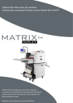
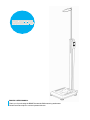
BSM370 USER’S MANUAL Thank you for purchasing the BSM370 automatic BMI measuring stadiometer. Please read manual prior to use and operate with care. ⓒ1996-2011 Biospace Co., Ltd. All rights reserved. Notice This user’s manual cannot be copied, translated or transformed into different media without a prior written consent from Biospace Co., Ltd, according to the copyright laws. This user’s manual and product pertinent to this manual may have misprints or technical flaws, which can be modified without prior notice to the readers. Biospace is not liable for any damage caused by failure to meet the requirements in this user’s manual. Biospace Co., Ltd. 518-10 Dogok 2- dong, Gangnam-gu, Seoul 135-854 KOREA TEL : 82-2-501-3939 FAX : 82-2-501-3978 Homepage : http://www.e-inbody.com E-mail : [email protected] Acknowledgements Biospace, InBody, Lookin’ Body are the registered trademarks of Biospace Co., Ltd. The names of the companies and products in this manual other than those of Biospace Co., Ltd. are the trademarks of the companies. Stating the products of other companies is strictly for the purpose of providing information, and not to guarantee or recommend the products. Biospace is not responsible for the performance or the use of these products. Biospace reserves the right to modify the dimensions or exterior of the BSM370 to improve the quality of the product, without consent of the customer. BM-ENG1-98-E-111110 Introducing the BSM370 Thank you for purchasing this Biospace BSM series device. The BSM series is a sophisticated product line developed by Biospace Co., Ltd. This product measures personal weight and height, thereby calculating BMI. It will help to improve health by comparing your BMI to the standards based on gender. It is also used to monitor health and fitness by observing the changes in BMI over the course of time. It can be used in both the healthy and acute or chronically ill population. The results may be of value to health care professionals in the management of diseases or conditions in which the disease, condition, or the treatment can affect BMI measuring. It is important to preventive medicine by providing the basis for appropriate physical activity and dietary formulas improving personal daily routine. It can be also usefully applied to follow-up studies on patients treated for various diseases With a dedication to the production of quality products and research and development, Biospace remains a reliable medical equipment provider. Kichul Cha, CEO Contents How to use this manual Safety Information Indicators & Safety Symbols Workplace Requirements Ⅰ Ⅱ Ⅴ Ⅵ Chapter 1 Installation & Maintenance 1. Contents of the Box 2. Exterior & Functions 3. Installation Instructions 4. Connecting to Optional Equipment 5. Transportation 6. Repacking 7. Correct Method for Transporting 8. Maintenance 1 3 5 9 15 16 18 19 Chapter 2 Management & Results Description 1. Exterior and Functions of Keypad 2. Connecting Power 3. Proper Posture 4. Measurement Mode 5. Results 21 23 24 25 28 Chapter 3 Setup Establishment 1. Setup 2. Setup Menu 30 31 Chapter 4 Problems & Solutions 1. Error Messages 2. Troubleshooting 33 34 Chapter 5 Appendix 1. Consumables 2. Options 3. Specifications 4. Customer Service Information 35 36 37 38 How to use this manual This user’s manual explains the functions of the BSM370. Follow the instructions below for effective use. 1. Please read this manual thoroughly prior to BSM370 operation. 2.Take a few moments to review the manual of this product in order to understand configuration. 3. If you have clinical issues while using the BSM370, please contact Biospace customer service. E-mail : [email protected] 4. Read symbols carefully. The following are representations of these symbols. Important information to warn of situations which might cause major injury and/or damage to property if instructions are not carefully followed. Important information to warn of situations which might cause minor injury and/or damage to property if instructions are not carefully followed. Important and helpful information for operation. I Safety Information 1. This product should always be placed on the ground and plugged into a secure electrical outlet. 2. Physically disabled persons or children should receive assistance when measuring on the BSM370 in order to obtain accurate results and avoid injury. 3. Do not insert or remove the power cord with wet hands. 4. Do not jump or apply severe shock to the foot plate as this may cause incorrect measurement or malfunction. 5. To prevent damage, please use a socket connected to appropriate power supply(100240VAC). If the socket has several terminals, a socket or extension cable with enough electric capacity should be used. 6. To avoid electrical shock, be sure to avoid contact between this product and other devices. 7. Use caution when raising or folding the stand of the equipment to avoid injury. When the stand is raised, do not touch the joints or any other moving part of the stand. Moving parts may cause injury if care is not taken. 8. Do not dismantle the equipment or open the back cover. Internal parts are not for customer use. If the equipment is dismantled, the warranty is void, and service costs will be charged. If service is required, contact Biospace or the supplying agency. 9. Follow local governing ordinances and recycling plans regarding the disposal or recycling of device components. II 1. Cross contamination Individuals with any kind of contagious disease or infection must not use or come in to contact with the foot plate or this product. Please be sure to clean the foot plate with appropriate disinfectant after each use. Never pour any liquid directly on the foot plate, as it may cause internal damage. Use a soft cloth and appropriate ethyl alcohol to wipe off the foot plate. Do not wipe the foot plate with strong chemicals. 2. Test result interpretation and prescription Do not start weight control or exercise therapy without physician’s prescription or expert’s advice. Misguided self-diagnosis may harm your health. If you are pregnant, please consult with undertaking physician or expert before use. 3. Other equipment Please block electromagnetic interferences from other equipment. It may lead to inaccurate test result or error. 4. This product must be installed on a flat and stable floor. If the floor is not level, it may cause harm or incorrect measurement. 5. Make sure you use the AC adapter provided by Biospace. Using other AC adapters may cause malfunction of the product. 6. Be careful not to spill or drop any residue(food or beverage) on this product. It may cause serious damage to the electronic components. 7. Do not move during measurement for accurate test results. 8. Be careful not to injure your fingers on the edge of the foot plate when handling the screws. III 1. Incorrect installation contrary to manual guidelines, or other equipment interference, may cause error or inaccurate test results. To solve the interference problem, you should: -Separate power supply from the equipment that is causing interference. -Isolate the equipment. -Use a power supply committed only to the device. -Please contact Biospace if the problem continues. 2. Excessively high or low temperatures, humidity and pressure may affect the equipment operation and may cause errors. Please use the equipment within the suggested specification range for use. 3. While moving, installing, or using this product, be sure to protect against any physical shock or damage. Always use the packing material and the original shipping box when moving or transporting this product. 4. Repair and examination should be conducted only by Biospace’s professional Customer Service staff. Please contact Biospace if needed. 5. The BSM370 fulfills the Standards of IEC61010-1(EN61010-1), Safety requirements of Electrical Equipment. In addition, the BSM370 complies not only Noise Immunity, but also Noise Emission by the Standard IEC61000(EN61000),Electromagnetic Compatibility Requir ements(EMC requirements). 6. The BSM370 has been designed, manufactured, and inspected under the full quality assurance system of Biospace. Biospace fulfills the international standardization system, ISO 90001 and ISO 13485. IV Indicators & Safety Symbols A. Indicators B. Safety Symbols V Workplace Requirements A. Operation Environment Temperature range 10 ~ 40 ℃ (50℉ ~ 104℉) Relative humidity 30 ~ 75 % Atmospheric pressure range 70 ~ 106 kPa Rated operating altitude ≤ 2000 m Pollution degree Ⅱ B. Transport and Storage Environment Temperature range -20 ~ 70 ℃ (-4℉ ~ 158℉) Relative humidity 10 ~ 95 % (No condensation) Atmospheric pressure range 50 ~ 106 kPa C. Adapter Power Input AC 100 – 240 V~, 50/60 Hz, 1.0A Power Output DC 12V, 3.33A Note. The following adapter must be used : Manufacturer : Li Shin International Enterprise Corp. AC/DC adapter model : LSE 0107A1240 Input : AC 100-240V~; 50.60Hz;1.0A Output : DC 12V, 3.33A This AC/DC adapter complies with UL 60950-1 and was approved. The power input for BSM370 shall not exceed the marked rating by more than 10%. VI Chapter 1. Installation & Maintenance 1. Contents of the Box 2. Exterior & Functions 3. Installation Instructions 4. Connecting to Optional Equipment 5. Transportation 6. Repacking 7. Correct Method for Transporting 8. Maintenance VII 1. Contents of the Box When opening the box, make sure all of the following items included. A. Included Items ① BSM370 ② Quick Reference ③ User’s manual CD ④ Adapter (12V, 3.33A) 1EA ⑤ Power cord (AC 250V, 10A, 1.8m (5ft. 10in.)) 1EA ⑥ Screw ⑦ Joint cover 1 B. Optional ⓛ Thermal printer 1EA , Thermal printer base , Screw(M4 X8) 6EA, Cable (95cm (3ft. 1in.)) ② Remote control device, Cable (2m,10cm (6 ft. 7 in., 4 in.)) ③ Y-type cable Remote control device is provided attached to the thermal printer. Always use the ③Y-type cable provided by Biospace to ensure proper communication with the InBody and remote control device. 2 2. Exterior & Functions Individual part identification and functions with schematic sketches are provided below. Please inspect each component of the BSM370 for damage prior to installation. 3 A. Connection Unit & Power Switch ① 9pin Serial Port, Female (RS-232C) Use to connect thermal printer provided by Biospace. ② Power Input Port Use to connect the power adapter. ③ Power Switch Power the BSM370 on/off. Do not dismantle the BSM370. Internal parts are not for customer use and may cause electrical shock. If the BSM370 is dismantled, the warranty is void, and service costs will be charged. Do not drop any food or liquid on the BSM370. It may affect the electrical parts in the BSM370 or cause damage. Use only the power cord provided by Biospace to connect to the power port. When using the adapter cable, insert the adapter cable tightly into the BSM370. 4 3. Installation Instructions A. Workplace requirements (1) Location: Indoor only. This device is for indoor use only. (2) Operation environment: 10 ~ 40℃(50 ~ 104 °F), 30 ~ 75%RH, 70 ~ 106kPa (3) Adapter: Power Input 100-240V ~, 50/60Hz, 1.0A Power Output DC 12V, 3.33A Please check the height from the ground to the ceiling before installing BSM370. It should be at least as tall as 2156mm (84.9in.) BSM370’s height is 2126mm (83.7in.) B. Note on Unpacking & Assembling Be sure to read these instructions carefully before assembling. (1) Place the BSM370 on a level floor. (2) Do not move while holding the head bar or operation panel with LCD. 5 C. Unpacking & Assembling (1) When opening the box, check to make sure all the items are included. Place the BSM370 horizontal to the ground. (2) Raise the stand of the BSM370 carefully until it stands upright. Tighten the joint screw at the base where the stand and foot plate meet. In case of a loose connection between the stand and the foot plate, measurement process cannot be performed properly. Attach the stand perpendicular to the foot plate. Use caution when handling screws to avoid injury. 6 (3) After the upper part of the BSM370 is fixed, close the joint cover. (4) Loosen the screws for the head bar and raise until horizontal with floor. Then tighten the screws. Make sure the screw of the head bar is firmly fixed. If it is not, it can make the height measurement inaccurate. The head bar and the stand should be always at a right angle. To prevent damage, do not lift head bar further than a 90 degree angle. 7 (5) Use the bubble level indicator on the BSM370 to check it is leveled. Use the leveling screws underneath the foot plate of the BSM370 if it is not leveled. <Unleveled state> <Raise> <Leveled state> <Lower> If the equipment is not horizontally leveled, adjust the leveling screw on the opposite side of the bubble to place it at the center of the level indicator. 8 4. Connecting to Optional Equipment The BSM370 can be used with a thermal printer, a remote control device, and the InBody. You have to check the cable when connecting the optional devices to the BSM370. Please refer to the following pictures and connect the optional devices. A. When you use thermal printer Necessary cable: Thermal printer cable ① Connect the thermal printer firmly to the thermal printer base. Fasten 4 screws to fix them together. ② Remove the sticker on the side of the stand. Adjust the thermal printer tray’s screw hole to the one of the stand. Screw tightly. 9 ③ Thermal printer cables must be connected in the same manner as shown in the picture. <rear part of the thermal printer> <rear part of the foot plate> ④ Place the printer paper as illustrated in the picture. Pull the end of the paper out of the printer by 1cm Only the thermal printer provided by Biospace can be used with the BSM370. 10 B. When you use InBody Necessary cables: Y-type cable, RS-232C cable Y-type Cable ① After connecting the RS-232C cable to the Y-type cable, ② Connect the RS-232C cable to the InBody. 11 C. When you use thermal printer and InBody Necessary cables: Y-type cable, Thermal printer cable, RS-232C cable Y-type Cable Connect the thermal printer cable to the Y-type cable. ① After connecting the RS-232C cable to the Y-type cable, ② Connect the RS-232C cable to the InBody. 12 D. When you use remote control device Necessary cables: Remote control device cable 10cm(4in.) Cable 2m(6ft. 7in.) Cable 13 E. When you use remote control device and InBody Necessary cables: Y-type cable, Remote control device cable (2m,10cm (6 ft 7 in, 4 in) RS-232C cable 10cm(4in.) Cable 2m(6ft. 7in.) Cable ① After connecting the RS-232C cable to the Y-type cable, ② Connect the RS-232C cable to the InBody. 14 5. Transportation It is not recommended to move the BSM370 once it is installed. If relocation of BSM370 is necessary, follow the safety precautions. (1) Turn the power off and remove the power adapter before moving the BSM370. (2) Be careful not to damage the operation parts. (3) Adjust the leveling screws on the foot plate to keep the BSM370 level. A. Environmental Requirements Transport and Storage environment : -20 ~ 70℃(-4℉ ~ 158℉), 10 ~ 95%RH 50 ~ 106kPa (No condensation) B. Transporting Before Installation Before installation, the BSM370 is shipped a packing box provided by Biospace. Use a dolly or cart to move the box or have two people from both sides for safe transportation. A strong impact or large shock during moving of the BSM370 may cause inaccurate measurements or damage to the unit. C. Transporting After Installation It is not recommended to move the BSM370 once properly installed. If relocation of the BSM370 is necessary, repack the BSM370 with original packing material, to keep the BSM370 from being damaged during transportation. After moving the BSM370, adjust the level of the BSM370 using the bubble level indicator and legs of the BSM370. The level of the BSM370 is crucial to accurate testing. 15 6. Repacking Be sure to turn off the power switch and unplug the power cable before repacking. Be careful to avoid severe physical shock, jarring, or other damage while repacking, especially with regard to the head bar and operation panel. (1) In the home screen, press ▼ for 3 seconds until you hear a beep. The head bar will go down automatically. Turn off the power switch. (2) Remove all cables connected to the BSM370. (If a thermal printer is attached to the unit, remove the thermal printer first.) (3) Unscrew at the head bar side and fold down. Tightly screw the joint. The head bar is sensitive, do not physically damage the head bar. (4) Open the joint cover. Remove joint cover on the foot step and fold the stand. If the joint cover is not removed before folding the stand, the product can be severely damaged. 16 (5) Loosen the screw on the foot plate. Slowly fold the stand of the BSM370 carefully. <side of the foot plate> Use caution when handling screws to avoid injury. Do not touch the joint part by hand or with any other part of the body. Injury may be caused if contact is made with moving parts. (6) Put the BSM370 in the box (7) Seal the box with tape. 17 7. Correct method for Transporting Shown below is the correct method for transporting BSM370. While moving this product, be sure to protect against any physical shock or damage. (1) On the home screen, press ▼ for 3 seconds. Head bar will go down automatically. Turn off the power switch. (2) Unscrew the head bar’s side and fold down. Tightly screw the joint. (3) Use the wheels on the foot plate to move the equipment. 18 8. Maintenance (1) Do not dismantle the BSM370 or open the back cover. Internal parts are not for customer use. If the BSM370 is dismantled, the warranty is void, and service costs will be charged. If service is required, contact Biospace or the supplying agency. (2) Do not place anything on the foot plate or apply any pressure when the BSM370 is not in use. (3) When the BSM370 is not in use for a period longer than one day, unplug the adapter. (4) Do not move or relocate the BSM370 while the power is on. (5) Do not drop any food or liquid on the BSM370. It may affect the electrical parts in the BSM370 or cause damage. (6) Once a week, wipe the exterior sides of the BSM370 with a dry towel. In particular, clean the LCD monitor, using care to not scratch the surface. (7) Follow local governing ordinances and recycling plans regarding the disposal or recycling of device components. (8) Lithium coin-cell battery is included in the “Operation panel”. This battery must be replaced only by Service Personnel. Be cautious there is a risk of explosion if battery in the operation panel is replaced by an incorrect type. 19 This operation panel includes lithium coin-cell battery. Only for service personnel. Risk of Explosion if battery in the operation panel is replaced by an incorrect type. 20 Chapter 2. Management & Results Description 1. Exterior and Functions of Keypad 2. Connecting Power 3. Proper Posture 4. Measurement Mode 5. Results 21 1. Exterior and Functions of Keypad 1) 4) 2) 3) 5) 1) LCD Monitor The monitor displays message or test results. 2) Direction Button The directional buttons consist of up, down, left and right. This button is used when set for measurement mode or setting up the BSM370. 21 3) ENTER/CLEAR Button ① ENTER : This button is used to store modified values at setup menu. ② CLEAR: Pressing this button to erases the result data on LCD right after test completion. Press it for 1 sec to return to the home screen. ③ Zero point adjustment : Press this button for a second until you hear beep to adjust zero point automatically. 4) MODE(▲) Button This is to select measurement mode. 5) SETUP(▼) Button Use the SETUP button to set up the BSM370. 6) (▲) (▼) Button This is to move the head bar up and down. Press ▼ Button for 3 seconds until you hear the beep. The head bar will move down automatically. On LCD, you will see ‘OFF’. To turn on the equipment, press ▲ button for 3 seconds until you hear the beep. The head bar will move up as far as it can go up. On LCD, you will see ‘ON’. 22 2. Connecting Power (1) Connect the BSM370 power adapter behind the foot plate. Make sure you use the power adapter provided by Biospace, and the power cable provided by Biospace. (2) Turn on the power switch. The head bar of BSM370 will automatically raise after turning the device on. Be careful not to put any weight on the foot plate. If you step on the foot plate or place a heavy object on the foot plate, it will disrupt calibration and measurements will not be accurate. When pressure or weight is applied to the foot plate during self-calibration, message appears. Turn the BSM370 off and on again after removing the material from the foot plate. 23 3. Proper Posture Observing the following methodology is essential to achieving reliable results and accuracy. Keep the following instructions in mind during testing. As you can see in the picture below, the proper posture for measurement is standing straight and having your arms and legs spread naturally. Remove heavy clothing and accessories in order to achieve an accurate weight measurement. (1) Step on the foot plate and position your back towards the stand. (2) Stand up straight and do not lean on the stand. (3) Maintain erect posture until measurement is complete and results are obtained. Physically disabled persons or children should receive assistance when measuring on the BSM370 in order to obtain accurate results and avoid injury. Leaning on the stand will incorrectly distribute weight, causing results to be inaccurate. Do not lean on the stand during measurement. 24 4. Measurement Mode Press the 'MODE' button in the home screen. Using ▲,▼,◀,▶ buttons, select the desired mode. When finished, press 'ENTER' to save. You will return to the measurement home screen. Weight: Weight measurement mode ① : When the examinee steps on the foot plate, the screen shows the weight. When the examinee steps down from the foot step, the test result will be displayed. When the test result disappears, it is ready for re-test. 25 Height : Height measurement mode ② : When the examinee steps on the foot plate, the height is automatically measured. ③ : When the examinee steps on the foot plate, you can measure height by pressing the 'ENTER' button. 26 BMI : Weight and Height measurement mode After weight and height are measured, the screen will show the measured height, weight, and the calculated BMI. ④ : When the examinee steps on the foot plate, the weight and height are automatically measured. ⑤ : When the examinee steps on the foot plate, the weight is automatically measured. You can measure height by pressing the 'ENTER' button. The default measurement mode is set as BMI when the system leaves the factory. 27 5. Results A. Weight, Height, BMI results screen When the test completes, the test result displays on LCD screen. The examinee can check the test result on LCD while he or she is on the foot plate. When the examinee steps down from the foot plate, the BSM370 will return to the home screen, which is also the stand-by screen before measurement. Please see the example below when it is set for BMI <Results Screen> automatic measurement mode. <Thermal Printer Paper> Customers in the US will be provided the lb/in version of the LCD and result paper. The BSM370 provides the following information through the analysis results screen. 1) Weight 2) Height 3) BMI 28 B. Output items BMI (Body Mass Index, kg/m2) Body Mass Index is a convenient way of assessing the degree of obesity. BMI is determined using only weight and height. Formula BMI = weight (kg) / height2 (m2) Determination 1) WHO Standard European weight classification based on the BMI method (WHO, 1998) BMI(kg/㎡) Classification Diagnosis <18.5 Underweight Under Infectious disease, malnutrition related disease 18.5~24.9 Normal Standard Least risk at most disease 25.0~29.9 Overweight 30.0~34.9 Obese1 35.0~39.9 Obese2 >40 May cause health problem Over Severely Obese Increase of the risk of cardiac disease, high blood pressure, diabetes, etc Ref. WHO and the National Heart, Lung, and Blood Institute : clinical guidelines on the identification, evaluation, and treatment of overweight and obesity in adults, the evidence report. June 1998, xiv Determination 2) Asian-Pacific Standard BMI(kg/㎡) <18.5 18.5~22.9 >23 Classification Underweight Normal Diagnosis Low (high risk of other clinical disease) Average Overweight 23.0~24.9 Risky Overweight Increased 25.0~29.9 Obese step1 Moderate >30 Obese step2 Severe Ref. Korean Society for the Study of Obesity, chapter 2. Redefining and Evaluation, The Asian-Pacific perspective: Redefining Obesity and its Treatment: 1st edition, Korean Society for the Study of Obesity, 2001, p10. 29 Chapter 3. Setup Establishment 1. Setup 2. Setup Menu 30 1. Setup The BSM370 functions to modify the setting for a user’s preference. The setup menu consists of weight offset, unit and date & time. Press the BSM370 'SETUP(▼)' button bring up the following screen. If you want to save the changes, press the ‘ENTER’ button. 1) Press the 'SETUP(▼)' button. 2) Press the direction buttons (◀,▶) to select area to modify. 3) Modify using direction buttons(▲,▼). 4) When you are finished with the modification, press the 'ENTER' button. 30 2. Setup Menu A. Weight Offset Press the BSM370 'SETUP(▼)' button to bring up the following screen. It is possible to adjust weight offset value. If weight adjustment is needed due to clothes or accessories, use the direction buttons(▲,▼) to select the desired offset value. (Calibration range: 0.0lb. ~ 9.9lbs., step : 0.1lb. or 0.0kg ~ 5.0kg, step: 0.1kg) B. Unit Press the '▶' button to advance from the weight offset screen. Use the direction buttons(▲,▼) to select the unit to be used for height and weight. (kg/cm, lb./in.) 31 C. Date & Time Press the '▶' button to advance from the unit screen. Use the direction buttons(▲,▼) to set the date and time. (1) Set the current year. (2) Set the current month and date. (3) Set the current hour and minute. D. Speed Press the '▶' button to advance from the Date & Time screen. Use the direction buttons(▲,▼) to set the speed. ① : Height measurement starts four seconds after the weight measurement regardless of user's movement. ② : Height measurement starts when a user stand still in stable position. 32 Chapter 4. Problems & Solutions 1. Error Messages 2. Troubleshooting 33 1. Error Messages The BSM370 displays the following error messages to warn the user of the problems that may occur during operations and to guide the users to take steps. The following are the most common error messages and the steps to handle the corresponding errors. Error Message Cod 1 Cod 2 Cod 3 Troubleshooting When pressure or weight is applied to the foot plate during self-calibration, this message appears. This message appears when the examinee’s weight is out of range. (Weight range :10kg ~ 250 kg(22 ~ 551lbs.) This message appears when adjusting zero point and foot plate weight is measured (0 kg ~ 2.1 kg (0~4.4lbs.)load). When the following message is displayed on LCD, semi-automatic zero point adjustment is not available. The above is the message on LCD. Turn the BSM370 off and on again after removing the material from the foot plate. Please check the weight measurement range. Turn the BSM370 off and on again after removing the material from the foot plate. This message appears when BSM370 has detected a problem that a user cannot solve. In this case, the height can be measured but the measured data may be incorrect. If you still have the problem after taking the following steps, contact the local distributor or Biospace. For more contact information, please refer to page 37. Error Message Troubleshooting Err 1 When the extensimeter is warming up, this message appears if the photo sensor is not working normally. Err 2 Err 3 When the extensimeter is warming up, this message appears if the data memory is not working normally. Err 4 Err 5 This message appears when top photo sensor is not working normally. Err 6 This message appears when the bottom photo sensor is not working normally. Err 7 This message appears when the photo sensor is not working normally under height calibration. 33 2. Troubleshooting If you still experience the problem after taking the following steps, contact the local distributor or Biospace. . For more contact information, please refer to page 37. A. The BSM370 does not seem to run, even if the power switch is on. (In a normal situation, a signal sounds and the LCD is turned on.) Cause 1 The plug is not pushed all the way into the electrical outlet. Actuion1 Push the plug all the way into the electrical outlet. Cause 2 Power strip is not turned on (when using a surge protector) or the power does not flow into extension. Action 2 Check if the power flows into the extension and the electrical outlet where the extension is connected. Cause 3 When an adapter not provided by Biospace is used. Action 3 Only use the adapter provided by Biospace. Cause 4 Adapter is not tightly inserted into the BSM370. Action 4 Insert the adapter into the power input port tightly. B. The measured weight value seems very low, or shows a negative value. Cause 1 The weight sensor (loadcell) calibration malfunctioned during the self-calibration. Action 1 Turn off the power of the BSM370, then turn it on again. Allow the unit to perform the self-calibration process again with no weight on the foot plate. The loadcell will be set to 0 kg during self-calibration. Keep in mind, even a small amount of weight affects the calibration negatively. Action 2 Press ‘ENTER’ button for zero setting. C. The thermal printer paper is not printing. Cause1 Occurs when the printer cable is unplugged. Action 1 Ensure the cable is connected tightly to the BSM370. Occasionally this may occur as the result of a bad cable. In this case, you must replace the cable. 34 Chapter 5. Consumables 1. Consumables 2. Options 3. Specifications 4. Customer Service Information 1 1. Consumables Roll of Thermal Printer Paper Size : Width 57mm (2.24in.) External diameter 45mm (1.77in.) Only use the thermal printer paper provided by Biospace. 35 2. Options A. Thermal Printer Only the thermal printer provided by Biospace can be used with the BSM370. The thermal printer should be connected to the serial port. Please contact Biospace or the local distributor of Biospace for further information. B. Remote control device You can operate the equipment remotely by connecting the remote control device to BSM370 with 2M cable. 10cm(4in.) Cable 2m (6ft. 7in.) Cable Remote control device is sold separately. Remote control device is provided with attached thermal printer. 36 3. Specifications Key Specifications Measurement Item Height Range Error Range Weight Range Height, Weight, BMI 90 ~ 200cm(2ft. 11.4in. ~ 6ft. 6.7in.) ± 1mm 10 ~ 250kg(22 ~ 551lbs.) Features Specifications Display Type Customized LCD Zero Setting Automatic zero setting during warming up Measurement Mode Weight and Height / Weight only / Height only A (Measure height after weight measurement) Height Measurement NA (Press ENTER button after measuring weight to measure height.) Unit: 0.1kg, from 0.0kg to 5.0kg Weight Offset Unit: 0.1lb., from 0.0lb. to 9.9lb. Unit Available to choose ‘kg/cm’ and ‘lb./in.’ Foldable height measuring part Portability Attaching wheels for carrying easily Optional Device Remote control device, Thermal printer Other Specifications AC 100-240V~, 50/60㎐, 1.0A Power Input Power Output DC 12V, 3.33A External Interface RS-232C 1EA Printer Thermal printer (Optional, the printers recommended by Biospace) Dimension When Head bar is down : 380(W) X 510(L) X 1350(H) mm 15(W) X 20(L) X 53.1(H) inch When Head bar is up : 380(W) X 510(L) X 2126(H) mm 15(W) X 20(L) X 83.7(H) inch Machine Weight 15.5kg(34lb.) Weight, Height Measurement : 7 sec. Measurement Duration Weight Measurement : 2 sec. Height Measurement : 5 sec. (standby time 2 sec.) Operation Environment 10 ~ 40℃(50 ~ 104℉), 30 ~ 75%RH, 70 ~ 106kPa Transport and Storage -20 ~ 70℃(-4 ~ 158℉), 10 ~ 95%RH Environment 50 ~ 106kPa(No condensation) * Specifications are subject to change without prior notice. Adapter 37 4. Customer Service Information Biospace Co., Ltd. [Head office] 518-10 Dogok 2- dong, Gangnam-gu, Seoul 135-854 KOREA TEL : 82-2-501-3939 FAX : 82-2-501-3978 Website : http://www.inbody.com E-mail : [email protected] Biospace Inc. [U.S.A] 4801 Wilshire Blvd. Suite 320 Los Angeles, CA 90010 U.S.A TEL : 1-323-932-6503 FAX : 1-323-932-6506 Homepage : http://www.biospaceamerica.com E-mail : [email protected] Biospace Japan Inc. [JAPAN] Second Floor Ayabe Bldg., 2-17-3 Sotokanda, Chiyoda-ku, Tokyo JAPAN TEL : 81-03-5298-7667 FAX : 81-03-5298-7668,7669 Homepage : http://www.biospace.co.jp E-mail : [email protected] DanilSMC Co., Ltd. [Asia] 3th Floor J Bldg., 35-25 Jamwon-dong, Seocho-gu, Seoul 137-905 KOREA TEL : 82-2-3462-5400 FAX : 82-2-3462-5105 E-mail : [email protected] EU Representative. [Europe] DongBang Acuprime. Gater House, Gater Lane, Palace Gate, Exeter, EX1 1JL, UK TEL : 44-1392- 273908 FAX : 44-1392- 273909 E-mail : [email protected] Biospace China. [CHINA] Block A, 26/F, Hai Xing plaza, No. 1 South Ruijin Road, Shanghai 200023, CHINA TEL : 86-21-64439738, 9739, 9705 FAX : 86-21-6443906 Homepage : http://www.biospacechina.com E-mail : [email protected] 38