1
SilverMax
Command Reference
Revision 3.23
May 2001
SilverMax™ and QuickControl™ are trademarks of QuickSilver Controls, Inc.
The SilverMax embedded software, SilverMax electronic circuit board designs, and the embedded logic in
the contained CPLDs, as well as this SilverMax Command Reference are Copyright © 1996-2000 by
QuickSilver Controls, Inc. SilverMax is covered under US Patent # 5,977,737
Table of Contents
SilverMax Command Set Overview ................................................................................................6
Command Structure .........................................................................................................................10
COMMAND NUMBERS .........................................................................................................................10
COMMAND PARAMETERS ...................................................................................................................10
SILVERMAX RESPONSE .....................................................................................................................10
Scaling ...............................................................................................................................................11
Filter Parameters.........................................................................................................................11
Position Parameters ....................................................................................................................11
Velocity Parameters ....................................................................................................................11
Acceleration Parameters .............................................................................................................11
Time Parameters.........................................................................................................................12
Command Types...............................................................................................................................13
IMMEDIATE TYPE COMMANDS .............................................................................................................13
PROGRAM BUFFER ............................................................................................................................13
PROGRAM TYPE COMMANDS .............................................................................................................13
COMMAND CLASSIFICATIONS .............................................................................................................14
Examples ...........................................................................................................................................15
SilverMax Commands – Detailed Description ...............................................................................16
STATUS COMMANDS ..........................................................................................................................16
Clear Poll (CPL) ..........................................................................................................................17
Poll (POL) ....................................................................................................................................19
Read I/O States (RIO) .................................................................................................................20
Read Internal Status Word (RIS) ................................................................................................21
Read Program Buffer (RPB)........................................................................................................22
Revision (RVN)............................................................................................................................23
OVERRIDE COMMANDS ......................................................................................................................24
Halt (HLT) ....................................................................................................................................25
Restart (RST) ..............................................................................................................................26
Single Step Exit (SSE) ................................................................................................................27
Single Step Program (SSP).........................................................................................................28
Stop (STP)...................................................................................................................................29
INITIALIZATION COMMANDS ................................................................................................................30
ACK DELAY (ADL)......................................................................................................................31
ANTI-HUNT CONSTANTS (AHC)...............................................................................................32
ANTI-HUNT DELAY (AHD) .........................................................................................................33
ANTI-HUNT MODE (AHM)..........................................................................................................34
BAUD RATE (BRT) .....................................................................................................................35
CALIBRATE ANALOG INPUT FROM NV (CAI) .........................................................................36
CONTROL CONSTANTS (CTC).................................................................................................37
DISABLE DONE BIT (DDB) ........................................................................................................38
DIGITAL INPUT FILTER (DIF) ....................................................................................................39
DIRECTION (DIR) .......................................................................................................................40
DUAL LOOP CONTROL (DLC)...................................................................................................41
DISABLE MOTOR DRIVER (DMD) ............................................................................................43
DISABLE MULTI-TASKING (DMT) .............................................................................................44
ENABLE DONE HIGH (EDH)......................................................................................................45
ENABLE DONE LOW (EDL) .......................................................................................................46
ENABLE MOTOR DRIVER (EMD)..............................................................................................47
ENABLE MULTI-TASKING (EMT) ..............................................................................................48
ERROR LIMITS (ERL) ................................................................................................................50
FILTER CONSTANTS (FLC).......................................................................................................52
GRAVITY OFFSET CONSTANTS (GOC) ..................................................................................53
IDENTITY (IDT) ...........................................................................................................................54
SilverMax Command Reference
Page ii
KILL DISABLE DRIVER (KDD) ...................................................................................................55
KILL ENABLE DRIVER (KED) ....................................................................................................56
KILL MOTOR CONDITIONS (KMC) ...........................................................................................57
KILL MOTOR RECOVERY (KMR) ..............................................................................................59
LOW VOLTAGE TRIP (LVT) .......................................................................................................60
MOTOR CONSTANTS (MCT).....................................................................................................61
MAXIMUM TEMPERATURE TRIP (MTT)...................................................................................62
OPEN LOOP PHASE (OLP) .......................................................................................................63
OVER VOLTAGE TRIP (OVT) ....................................................................................................64
PHASE ADVANCE CONSTANTS (PAC)....................................................................................65
POWER LOW RECOVERY (PLR) ..............................................................................................66
PROTOCOL (PRO) .....................................................................................................................67
S-CURVE FACTOR (SCF)..........................................................................................................68
SELECT EXTERNAL ENCODER (SEE).....................................................................................69
SERIAL INTERFACE (SIF) .........................................................................................................70
SINGLE LOOP CONTROL (SLC) ...............................................................................................71
SOFT STOP LIMITS (SSL) .........................................................................................................72
TORQUE LIMITS (TQL) ..............................................................................................................73
TORQUE RAMP UP (TRU).........................................................................................................75
MODE COMMANDS ............................................................................................................................76
GO CLOSED LOOP (GCL) .........................................................................................................77
GO OPEN LOOP (GOL)..............................................................................................................78
POSITION INPUT MODE (PIM)..................................................................................................79
REGISTERED STEP & DIRECTION (RSD) ...............................................................................80
SCALED STEP & DIRECTION (SSD) ........................................................................................81
TORQUE INPUT MODE (TIM)....................................................................................................83
VELOCITY INPUT MODE (VIM) .................................................................................................84
INPUT MODE USAGE (IMU) ......................................................................................................85
VELOCITY MODE, IMMEDIATE TYPE (VMI) ............................................................................87
VELOCITY MODE, PROGRAM TYPE (VMP) ............................................................................88
MOTION & PROFILE MOVE COMMANDS ..............................................................................................89
MOTION & PROFILE MOVE COMMANDS ..............................................................................................90
HARD STOP MOVE (HSM) ........................................................................................................91
INTERPOLATED MOVE START (IMS) ......................................................................................92
INTERPOLATED MOVE QUEUE CLEAR (IMQ) ........................................................................94
INTERPOLATED MOVE WRITE QUEUE (IMW)........................................................................95
MOVE ABSOLUTE, TIME BASED (MAT)...................................................................................97
MOVE ABSOLUTE, VELOCITY BASED (MAV) .........................................................................99
MOVE RELATIVE, TIME BASED (MRT) ....................................................................................101
MOVE RELATIVE, VELOCITY BASED (MRV)...........................................................................103
PRE-CALCULATED GO (PCG) ..................................................................................................105
PRE-CALCULATE MOVE (PCM) ...............................................................................................106
PROFILE MOVE CONTINUOUS (PMC).....................................................................................107
PROFILE MOVE OVERRIDE (PMO)..........................................................................................109
PROFILE MOVE (PMV) ..............................................................................................................110
PROFILE MOVE EXIT (PMX) .....................................................................................................111
REGISTER MOVE ABSOLUTE, TIME BASED (RAT) ...............................................................112
REGISTER MOVE ABSOLUTE, VELOCITY BASED (RAV) ......................................................113
REGISTER MOVE RELATIVE, TIME BASED (RRT) .................................................................114
REGISTER MOVE RELATIVE, VELOCITY BASED (RRV)........................................................115
EXTENDED REGISTER MOVE ABSOLUTE, TIME BASED (XAT) ...........................................116
EXTENDED REGISTER MOVE ABSOLUTE, VELOCITY BASED (XAV) .................................117
EXTENDED REGISTER MOVE RELATIVE, TIME BASED (XRT).............................................118
EXTENDED REGISTER MOVE RELATIVE, VELOCITY BASED (XRV) ...................................119
PROGRAM FLOW COMMANDS .............................................................................................................120
CALCULATION (CLC).................................................................................................................121
SilverMax Command Reference
Page iii
CLEAR PROGRAM (CLP) ..........................................................................................................124
DELAY (DLY) ..............................................................................................................................125
END PROGRAM (END) ..............................................................................................................126
JUMP ON INPUTS, AND-ED (JAN) ............................................................................................127
JUMP ON INPUTS, NAND-ED (JNA) .........................................................................................128
JUMP ON INPUTS, OR-ED (JOR)..............................................................................................129
JUMP (JMP) ................................................................................................................................130
JUMP ON INPUT (JOI) ...............................................................................................................132
JUMP ON REGISTER EQUAL (JRE) .........................................................................................134
LOAD PROGRAM (LPR).............................................................................................................135
LOAD AND RUN PROGRAM (LRP) ...........................................................................................136
PROGRAM CALL (PCL) .............................................................................................................137
PROGRAM CALL ON INPUT (PCI) ............................................................................................138
PROGRAM RETURN (PRT) .......................................................................................................139
PROGRAM RETURN ON INPUT (PRI) ......................................................................................140
RUN PROGRAM (RUN)..............................................................................................................141
START DOWNLOAD (SDL) ........................................................................................................142
STORE PROGRAM (SPR)..........................................................................................................143
WAIT ON BIT EDGE (WBE)........................................................................................................144
WAIT ON BIT STATE (WBS) ......................................................................................................145
WAIT DELAY (WDL) ...................................................................................................................146
I/O COMMANDS .................................................................................................................................147
ANALOG CONTINUOUS READ (ACR) ......................................................................................148
ANALOG READ INPUT (ARI) .....................................................................................................150
CONFIGURE I/O (CIO) ...............................................................................................................152
CLEAR OUTPUT BIT (COB).......................................................................................................153
DISABLE ENCODER MONITOR (DEM).....................................................................................154
ENABLE ENCODER MONITOR (EEM)......................................................................................155
MODULO CLEAR (MDC) ............................................................................................................156
MODULO SET (MDS) .................................................................................................................157
MODULO TRIGGER (MDT) ........................................................................................................158
POSITION COMPARE (PCP) .....................................................................................................159
SET OUTPUT BIT (SOB) ............................................................................................................160
DATA REGISTER COMMANDS .............................................................................................................162
ADD TO REGISTER (ATR).........................................................................................................164
REGISTER LOAD MULTIPLE (RLM) .........................................................................................165
REGISTER LOAD NON-VOLATILE (RLN) .................................................................................167
READ REGISTER (RRG)............................................................................................................168
REGISTER STORE MULTIPLE (RSM) ......................................................................................169
REGISTER STORE NON-VOLATILE (RSN) ..............................................................................171
WRITE REGISTER, IMMEDIATE TYPE (WRI) ..........................................................................172
WRITE REGISTER, PROGRAM TYPE (WRP) ..........................................................................173
WRITE CMD LONG WORD (WCL) ............................................................................................174
WRITE CMD WORD (WCW) ......................................................................................................175
MISC. COMMANDS .............................................................................................................................176
CLEAR MAX ERROR (CME) ......................................................................................................177
CLEAR INTERNAL STATUS (CIS) .............................................................................................178
CHECK INTERNAL STATUS (CKS)...........................................................................................179
TARGET TO POSITION (TTP) ...................................................................................................180
ZERO TARGET (ZTG) ................................................................................................................181
ZERO TARGET & POSITION (ZTP) ...........................................................................................182
Summary of SilverMax Commands: ...............................................................................................183
STATUS COMMANDS ..........................................................................................................................183
OVERRIDE COMMANDS ......................................................................................................................184
INITIALIZATION COMMANDS ................................................................................................................185
MODE COMMANDS ............................................................................................................................194
SilverMax Command Reference
Page iv
MOTION & PROFILE MOVE COMMANDS ..............................................................................................196
PROGRAM CONDITIONAL & FLOW COMMANDS ....................................................................................203
I/O COMMANDS .................................................................................................................................207
DATA REGISTER COMMANDS .............................................................................................................209
MISC. COMMANDS .............................................................................................................................211
SilverMax Command Set - Numeric/TLA List ................................................................................212
SilverMax Command Name Cross Reference Table .....................................................................216
Index ..................................................................................................................................................222
SilverMax Command Reference
Page v
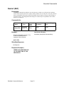
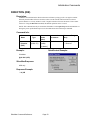
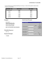
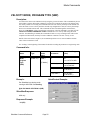
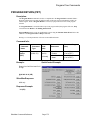
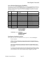
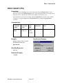
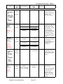
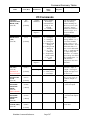
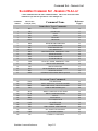
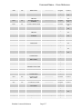
SILVERMAX COMMAND SET OVERVIEW
Status Commands are used to retrieve
information from SilverMax. These
commands can all be used while SilverMax is
executing a motion.
TLA Override Commands
HLT
RST
SSE
SSP
STP
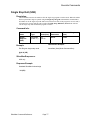
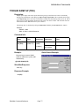
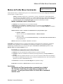
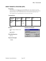
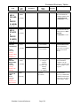
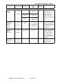
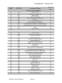
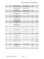
Initialization Commands setup the
SilverMax operating characteristics.
Typically these commands are placed in the
“Initialization” program but may also be used
during normal operation
TLA Initialization Commands
ACK Delay
Anti-Hunt Constants
Anti-Hunt Delay
AHM
BRT
CAI
CTC
DDB
DIF
DIR
DLC
DMD
DMT
EDH
EDL
EMD
EMT
Anti-Hunt Mode
Baud Rate
Calibrate Analog Inputs from NV
Control Constants
Disable Done Bit
Digital Input Filter
Direction
Dual Loop Control
Disable Motor Driver
Disable Multi-Task
Enable Done High
Enable Done Low
Enable Motor Driver
Enable Multi-Task
SilverMax Command Reference
POL
RIO
RIS
RPB
RVN
Poll
Read I/O States
Read Internal Status Word
Read Program Buffer
Revision
Override Commands can Halt, Restart
or Stop the SilverMax at any time.
These override any current operation
for greater control of the motor.
Program execution can also be
controlled.
Halt
Restart
Single Step Exit
Single Step Program
Stop
ADL
AHC
AHD
“TLA” = Three Letter Acronym
TLA Status Commands
CPL Clear Poll
Page 6
ERL
FLC
GOC
IDT
KDD
KED
KMC
KMR
LVT
MCT
MTT
OLP
OVT
PAC
PLR
PRO
SCF
SEE
SIF
SLC
SSL
TQL
TRU
Error Limits
Filter Constants
Gravity Offset Constant
Identity
Kill Disable Drivers
Kill Enable Drivers
Kill Motor Conditions
Kill Motor Recovery
Low Voltage Trip
Motor Constants
Maximum Temperature Trip
Open Loop Phase
Over Voltage Trip
Phase Advance Constants
Power Low Recovery
Protocol
S-Curve Factor
Select External Encoder
Serial Interface
Single Loop Control
Soft Stop Limits
Torque Limits
Torque Ramp Up
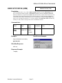
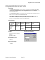
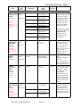
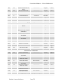
TLA Mode Commands
GCL Go Closed Loop
GOP Go Open Loop
PIM Position Input Mode(Actually Target
input)
RSD Registered Step And Direction
SSD Scaled Step And Direction
TIM Torque Input Mode
VIM Velocity Input Mode
VMI Velocity Mode, Immediate Type
VMP Velocity Mode, Program Type
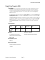
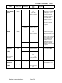
Motion Commands give SilverMax the
ability to follow a profile. All motion
commands will accelerate using
S-curve or linear ramps. SilverMax has
a unique ability to do motion profiles
using “Time” for the acceleration and
velocity parameters.
SilverMax Command Reference
Mode Commands put SilverMax into
required and special modes of operation.
Some modes give SilverMax the ability to
input analog or Step and Direction
signals for motion control.
TLA Motion Commands
HSM
IMS
IMQ
IMW
MAT
MAV
MRT
MRV
PCG
PCM
PMC
PMO
PMV
PMX
RAT
RAV
RRT
RRV
XAT
XAV
XRT
XRV
Page 7
Hard Stop Move
Interpolated Move Start
Interpolated Move Queue Clear
Interpolated Move Write to Queue
Move Absolute, Time Based
Move Absolute, Velocity Based
Move Relative, Time Based
Move Relative, Velocity Based
Pre-Calculated Go
Pre-Calculate Move
Profile Move Continuous
Profile Move Override
Profile Move
Profile Move Exit
Register Move Absolute, Time Based
Register Move Absolute, Velocity Based
Register Move Relative, Time Based
Register Move Relative, Velocity Based
Extended Register Move Absolute, Time Based
Extended Register Move Absolute, Velocity Based
Extended Register Move Relative, Time Based
Extended Register Move Relative, Velocity Based
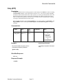
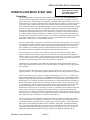
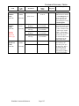
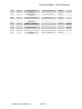
Program Flow Commands are at the
heart of SilverMax stand-alone
operation. Complex programs can be
created that provide a total motion
control solution without need for an
external “host” controller.
Programs can use I/O, Analog inputs,
or the serial link for conditional
operation. In many cases this ability
eliminates the need for a PLC in the
system.
TLA I/O Commands
ACR
ARI
CIO
COB
DEM
EEM
MDC
MDS
MDT
PCP
SOB
Analog Continuous Read
Analog Read Input
Configure I/O
Clear Output Bit
Disable Encoder Monitor
Enable Encoder Monitor
Modulo Clear
Modulo Set
Modulo Trigger
Position Compare
Set Output Bit
SilverMax Command Reference
TLA Program Flow Commands
CLC
CLP
DLY
END
JAN
JNA
JOR
JMP
JOI
JRE
LPR
LRP
PCL
PCI
PRT
PRI
RUN
SDL
SPR
WBE
WBS
WDL
Calculation
Clear Program
Delay
End Program
Jump on Inputs, And-ed
Jump on Inputs, NAND-ed
Jump on Inputs, Or-ed
Jump
Jump on Input
Jump Register Equal
Load Program
Load and Run Program
Program Call
Program Call on Input
Program Return
Program Return on Input
Run Program
Start Download
Store Program
Wait on Bit Edge
Wait on Bit State
Wait Delay
I/O Commands provide SilverMax
PLC-like qualities with 7 fully
programmable I/O lines. Special I/O
modes provide “Electronic Gearing”
and other external control capability.
Analog commands set up analog data
input into SilverMax. Analog data can
then be used by other commands and
modes for analog operations.
Page 8
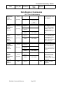
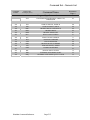
Data Register Commands allow data
management inside the SilverMax.
Data can be stored into and loaded
from Non-volatile memory to save
calibration, offset or other data values.
Several SilverMax commands can use
Data Registers as parameters.
TLA
CME
CIS
CKS
TTP
ZTG
ZTP
Miscellaneous Function
Commands
Clear Max Error
Clear Internal Status
Check Internal Status
Set Target to Position
Zero Target
Zero Target and Position
SilverMax Command Reference
TLA Data Register Commands
ATR
RLM
RLN
RRG
RSM
RSN
WCL
WCW
WRI
WRP
Add to Register
Register Load Multiple
Register Load from Non-Volatile
Read Register
Register Store Multiple
Register Store to Non-Volatile
Write Command Buffer Longword
Write Command Buffer Word
Write Register, Immediate Type
Write Register, Program Type
Miscellaneous Function Commands
wrap up some of those nice but
“ungroupable” commands. Most useful
are the Zero, Target and Position
commands that let the system set or
clear its current position.
Page 9
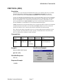
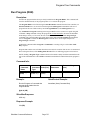
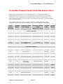
COMMAND STRUCTURE
SilverMax commands are setup with a simple structure that combines a command number with a set of
parameters. Commands may have from 0 to 8 parameters depending on the command itself. If a command has a
set of parameters, the parameters must be sent with the command even if they are not used.
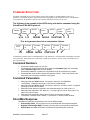
The following is an example of the ASCII string of a motion command using the
QuickSilver 8-Bit ASCII protocol.
Address
Command
(MRV)
@16 135
Position
Accel.
Velocity
Input
Enable
200000 161060 536871000 0
Input
States
0
This string breaks down into a command as follows:
Command
Number
135
Parameter
#1
Parameter
#2
Parameter
#3
Parameter
#4
200000 161060 536871000 0
Parameter
#5
0
Commands are organized into “Command Numbers” and “Parameters”. Each SilverMax command has a defined
set of parameters. Each parameter is separated by a single space character. In some cases, commands may not
have any parameters.
Command Numbers
•
•
•
•
Command numbers range from 0 to 255.
Commands with numbers less than 64 are Host level Immediate Type only commands
(See Command Types below for more details).
Command numbers 64 or greater are commands that can be contained in a program.
Commands with numbers 64 or greater will generate a “Busy” “NAK” code if sent to the
motor while it is executing a command or a program.
Command Parameters
•
•
•
•
•
•
Parameters that are 32-Bit “Signed” can range in value from -2147483648 to
+2147483647. “Unsigned” can range in value from 0 to 4294967295.
Parameters that are 16-Bit “Signed” can range in value from -32768 to +32767. “Unsigned”
can range in value from 0 to 65535.
Parameters must always be included in the command string even if the value is “0”.
Parameters that represent a “Bit” state are “1” for logic high (+5 volts on input) and “0” for
logic low (0 volts on input).
Parameters that represent a “Binary Word” must be converted to a number.
< parameter > denotes 16-Bit numbers, << parameter >> denotes 32-Bit numbers.
SilverMax Response
SilverMax will respond to a command in one of three different ways:
• Acknowledge (ACK). This is typical for most commands and is the simplest response.
• Negative Acknowledge (NAK). Something is wrong with the command or transmission.
• Specific Data. SilverMax information or Data that is requested by the command.
SilverMax Command Reference
Page 10
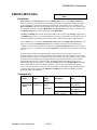
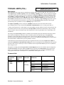
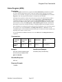
SCALING
Native SilverMax units are designed to take advantage of the entire parameter range whether it is 32 bit or 16 bit.
Because of this, converting from engineering units to Native SilverMax units requires some scaling. The
following sections describe scaling for the most popular command parameters.
Filter Parameters
The filter constants are calculated as follows:
Fv
F
T
Fvl
Filter Value (Native SilverMax Units)
Filter in Hz (Cutoff Frequency – 3dB down point)
Time Sample (120 microseconds)
Filter Value Limit (32768)
Fv = Fvl e-F2πT
F = - ln(Fv/Fvl)/(2πT)
Example: Position Input Mode (PIM) command with a 117Hz filter. The native SilverMax Filter Value is
30000.
30000 = 32768 e- (117)2π(120uS)
Position Parameters
The Position Value Units is in Encoder Counts. For a SilverMax with an encoder that provides 4000 counts per
revolution, one revolution of the motor is 4000 counts. To scale a move to revolutions, multiply the revolutions
value by 4000.
Velocity Parameters
The Velocity parameter is scaled internally as SilverMax velocity units. SilverMax velocity units are based on the
maximum velocity value “2,147,483,647” being equal to 4000 RPM. This yields the number 536,871 as equal to
one RPM.
To calculate Velocity in RPM, multiply the RPM value by 536,871.
Example:
200 RPM = 200 * 536,871 SVU = 107374200
Acceleration Parameters
The Acceleration value is scaled internally for SilverMax acceleration units. SilverMax acceleration units are
based on the maximum acceleration value “1,073,741,823” being equal to 2000 RPM in 1 servo cycle (0.00012
sec.). This yields the number 64.4245 as equal to one RPM/sec. Or the number 3865.47 as equal to one RPS/sec.
To calculate Acceleration in RPM/sec, multiply the RPM/sec value by 64.4245.
Example:
10000 RPM/sec = 10000 * 64.4245 (1/RPM/sec) = 644245
To calculate Acceleration in RPS/sec, multiply the RPS/sec value by 3865.47.
Example:
166.7 RPS/sec = 166 * 3865.47(1/RPM/sec) = 644373 (Almost the same as above)
SilverMax Command Reference
Page 11
Time Parameters
The Native SilverMax unit for time is a “Tick” which is one clock cycle at 8KHz or 120 microseconds. To
convert Ticks to seconds multiply by 0.00012. There are 8333 Ticks in one second.
SilverMax Command Reference
Page 12
COMMAND TYPES
The SilverMax command structure is divided into two major classifications: Immediate Type Commands and
Program Type Commands. The Immediate Type Commands may only be executed via the serial link, while
Program Type Commands may be executed via the serial link or from the non-volatile memory. Program Type
Commands are temporarily stored in the Program Buffer prior to execution. Before executing a Program, the
Program Buffer is filled with the given Program from either the serial communications or the non-volatile
memory.
Immediate Type Commands
Immediate Type Commands typically give an immediate result or return data when executed. Most of these
commands can be executed at any time even during SilverMax operation. Some Immediate Type Commands
cannot be executed simultaneous to Program Buffer operations. These commands and the conditions for execution
are noted in the command description. If command execution is attempted when not appropriate, SilverMax will
produce a NAK Busy response.
Immediate Type commands do not use the Program Buffer. They are executed as soon as they are received.
Immediate Type commands can only be used via the serial communications interface, they cannot be used
within a Program that is downloaded to SilverMax for Program execution. A “Host” controller may use
Immediate Type Commands to set up, control or maintain status of a SilverMax.
Program Buffer
Program Type Commands are executed out of the Program Buffer. When a command is received through the
serial communications, it is placed into the Program Buffer prior to execution. Because the buffer can store more
than one unexecuted command at a time, SilverMax is able to execute commands sequentially in the form of a
Program. Executing a Program allows for very accurate timing of complex motions. A Program that has been
stored in the Non-Volatile Memory must be loaded into the Program Buffer before it can be executed.
Program Type Commands
Program Type Commands can be executed either from the serial communications interface or from non-volatile
memory. Program Type Commands, as the name implies, can be part of a Program. When these commands are
sent, they are first loaded into the Program Buffer, and then executed. This requires that the buffer not be in use at
the time the command is sent. For example, they cannot be executed while the Load Program or Store Program
commands are active. If a Program Type Command is sent while the motor is active, a NAK Busy response is
returned.
Program Type Commands can also be downloaded to the Program Buffer without being executed. Once a
Program has been assembled, it can either be executed immediately or it can be written to the Non-Volatile
Memory. Programs can also be loaded from the Non-Volatile Memory and executed. In fact the SilverMax factory
initialization is a Program which starts at location “0” in the Non-Volatile Memory and is automatically executed
at the application of power.
SilverMax Command Reference
Page 13
Command Classifications
The SilverMax command set has been broken into the following classifications. Each class of command has a set
of rules that define how or when a command can be used.
NOTE: “executed” for this section means to “Send a command real-time from a Host
controller to SilverMax using the serial communications interface”
Class “A” Commands:
These are serial communications interface only. They may not be contained within a Program and their
execution does not incidentally affect the Program Buffer contents. They may be executed at any time.
Class “B” Commands:
These are serial communications interface only. They may not be contained within a Program, but their
execution affects the Program Buffer. They may be executed only while the motor is idle (No Motion or
Program is running).
Multi-Tasking allows these commands to be executed at any time providing the conditions are appropriate.
For example: the “Start Download” command should not be executed when a Program is running or when
already in Download mode.
Class “C” Commands:
These are serial communications interface only. They may not be contained within a Program, but their
execution affects the Program Buffer. They may be executed only while the motor is idle (No Motion or
Program is running). The Program Buffer must also be loaded prior to execution.
Multi-Tasking – Allows these commands to be executed when a Motion is running but not when a Program
is running.
Class “D” Commands:
These commands can be executed from the serial communications interface or as part of a Program. Their
execution from the “Host” affects the Program Buffer. They may only be executed when the motor is idle.
They are then stored to the buffer when in download (Program Download) mode. All of these commands
have a command code of 64 (hex 0x40) or higher.
Multi-Tasking – Allows these commands can be executed when a Motion is running but not when a Program
is running. Most commands will execute immediately while the “Motion” or “Profile Move” commands will
be buffered until the current Motion is complete.
Class “E” Commands:
These commands are executed as part of a Program. They may be executed from the serial communications
interface but should only be used within a Program or the motor operation may not be what is expected. They
rely on what has been previously loaded to the Program buffer for operation. They can only be executed when
the motor is idle. They will be stored to the buffer when in download (Program Download) mode. All of
these commands have a command code of 64 (hex 0x40) or higher.
Multi-Tasking – Allows these commands to be executed while a Motion is running, but operation may not
be what is expected as these are typically contained in a Program.
Class “F” Commands:
These are serial communications interface only. They may not be contained within a Program, but their
execution affects the Program Buffer. They may be executed while the motor is running or idle.
SilverMax Command Reference
Page 14
Examples
EXAMPLES
All examples are given in the ASCII 8 bit protocol.
SilverMax Command Reference
Page 15
Status Commands
SILVERMAX COMMANDS – DETAILED DESCRIPTION
Status Commands
Status commands are used to retrieve information from SilverMax. These
commands can all be used while SilverMax is executing a motion or a Program.
SilverMax Command Reference
Page 16
Status Commands
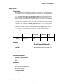
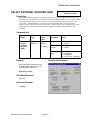
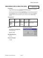
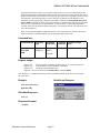
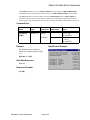
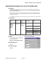
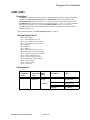
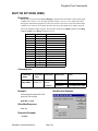
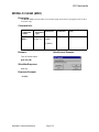
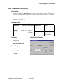
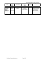
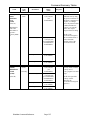
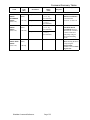
Clear Poll (CPL)
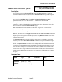
Description:
This is a complement to the Poll command. This command is used to clear the Polling Status
Word bits (See Polling Status Word below). When a status bit is set (“1”) it will remain set
until a Clear Poll command is sent with the same bit set in its Clear Status Word. For
example, if a Poll command gets back a Polling Status Word of “0x2000”, bit 13 set
(Program completed), of the Polling Status Word is set. To reset bit 13, the Clear Status
Word must be set to “0x2000”. This will cause bit 13 to be re-set (“0”). All other bits in the
Polling Status Word will be left unchanged if the corresponding clear bit is not set. New
occurrences since the last poll will NOT be cleared (the Status word is double buffered).
Command Info:
Command
Name
Command
Type
Command
Code (Hex)
Command
Parameters
Clear Poll
(CPL)
Immediate
(Class “A”)
1
(0x1)
< Clear Status
Word >
Example:
Clear only Bit #13 set in the Polling
Status Word
Decimal 8192 = 0x2000 in
Hexadecimal
QuickControl Example:
Immediate (Host) Mode Command Only
@16 1 8192 (CR)
Clear all the bits set in the Polling
Status Word
@16 1 65535 (CR)
SilverMax Response:
ACK only
Response Example:
* 10 (CR)
SilverMax Command Reference
Parameter
Range
(Hex)
0 to 65535
(0 to 0xFFFF)
Page 17
Status Commands
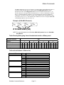
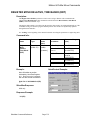
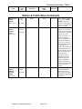
The Poll command has two types of responses: an Acknowledge, which indicates that there is
no status to send, and a data packet, which contains the Polling Status Word in ASCII
Hexadecimal format. The Polling Status Word is sent in 4 hexadecimal characters (0 – F).
The first character is the upper nibble and contains bits 15-12. The second character contains
bits 11-8. The third character contains bit 7-4. The final character is the lower nibble and
contains bits 3-0. Each bit represents a current or past condition of the SilverMax device that
was polled. If a bit is set (“1”) this indicates the condition has occurred. Using the Clear Poll
command individual bits can be cleared (“0”).
Example: (8-Bit ASCII Protocol)
1st
Char.
2nd
Char.
3rd
Char.
4th
Char.
# 10 0000 2000 (CR)
NOTE: For more information on the SilverMax 8-Bit ASCII protocol see the “SilverMax
User Manual”
Table Showing Data going from a Hexadecimal word to a Binary word
Hexadecimal Word
2000
Nibbles
2
0
0
0
Bit Values (For reference)
8
4
2
1
8
4
2
1
8
4
2
1
8
4
2
1
Bit # (for reference)
15
14
13
12
11
10
9
8
7
6
5
4
3
2
1
0
Binary Word
0
0
1
0
0
0
0
0
0
0
0
0
0
0
0
0
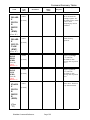
Table with definitions of Status bits
Returned Character
Bit #
Definition
1 character
Bit 15
Bit 14
Bit 13
Bit 12
Foreground Command Done
Foreground Command Error
Command or Program complete
Program errors
2nd character
Bit 11
Bit 10
Bit 9
Bit 8
Move terminated with sensor found
Low/Over Voltage
Position Error (Stopped)
Motion Error (Moving)
3rd character
Bit 7
Bit 6
Bit 5
Bit 4
Receiver overflow
Check Bit return Status (if condition found)
Too long of message
Framing Error
4th character
Bit 3
Bit 2
Bit 1
Bit 0
Motor shut down (Kill Motor Condition)
Soft/Hard Limit
Checksum error
Aborted packet - data errors or new address frame
st
SilverMax Command Reference
Page 18
Status Commands
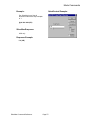
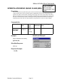
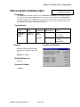
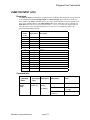
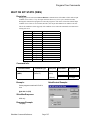
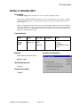
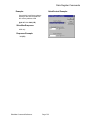
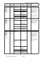
Poll (POL)
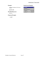
Description:
This command is used to determine the condition of a SilverMax unit. A Poll command can
be executed at any time, including while SilverMax is in motion. Executing this command
will cause the addressed SilverMax unit to return either an ACK (if no bits of the status are
set), or the Polling Status Word. The Polling Status Word contains information about the
current state of the SilverMax (See Polling Status Word Section in the SilverMax User
Manual). The Poll command can be used when checking to see if a motion has completed.
This is useful when a system must wait for a SilverMax to complete its operation before
performing the next operation. It may also be used to verify that the last motion completed
without any motion or position errors when the ERROR LIMIT command has been used to
set up motion error conditions. The Polling Status Word bits are “Set” when the particular
condition takes place. The bits are “re-set” using a Clear Poll command (See Clear Poll
command above). Note: Additional conditions that occur after a Poll will show up in the
following Poll even if those bits have been cleared in an intervening Clear Poll command.
(i.e. they cannot be cleared until they have been read - the data is double buffered.)
Command Info:
Command Name
Poll
(POL)
Command Type
Command
Code (Hex)
Command
Parameters
Immediate
(Class “A”)
0 or NONE
(0x0)
NONE
Example:
Poll without command number
@16 (CR)
QuickControl Example:
Immediate (Host) Mode Command Only
Poll with command number
@16 0 (CR)
SilverMax Response:
ACK only or Pulling Status
Word 0 to 65535 (0000 to
FFFF)
Response
Example:
This is the SilverMax response
with status – Indicates
Command/Program Complete.
# 10 0000 2000 (CR)
* 10 (CR)
SilverMax Command Reference
Parameter
Range
(Hex)
NONE
Page 19
Status Commands
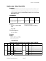
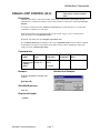
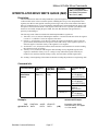
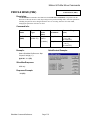
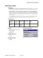
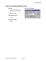
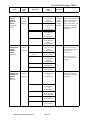
Read I/O States (RIO)
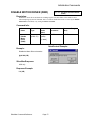
Description:
The I/O State Word is available for reading back the states of miscellaneous I/O conditions.
This word may need to be read if more information on the motor status is required. For
example: The upper I/O lines #4 to #7 may need to be read by a “Host”. This word is dynamic
and may change every servo cycle (120 usec.)
Command Info:
Command
Name
Command
Type
Command
Code (Hex)
Command
Parameters
Read I/O
States (RIO)
Immediate
(Class “A”)
21
(0x15)
NONE
Parameter
Range
(Hex)
NONE
QuickControl Example:
Example:
Immediate (Host) Mode Command Only
Read back the I/O State Word
@16 21 (CR)
SilverMax Response:
I/O State Code 2 Bytes
Response
Example:
Indicates lines #4, 5, 6, & 7 are
“High” and lines #1, 2 & 3 are
also “High”
# 10 0015 F0F0 (CR)
Table Showing the Bit definitions for the I/O State Word (IOS)
Nibbles
“F”
“0”
Bit #
Bit 15
Bit 14
Bit 13
Bit 12
Bit 11
Bit 10
Bit 9
Bit 8
IOS bit # 15-8
definitions
I/O #7
I/O #6
I/O #5
I/O #4
reserved
Delay Counter Active
Holding Error
Moving Error
SilverMax Command Reference
Nibbles
“F”
“0”
Bit #
IOS bit # 0-7 definitions
Bit
Bit
Bit
Bit
Bit
Bit
Bit
Bit
Over Temperature (“0” = True)
I/O #3
I/O #2
I/O #1
Trajectory Generator Active
External Index
Internal Index
INDEX (Multiplexed)
Page 20
7
6
5
4
3
2
1
0
Status Commands
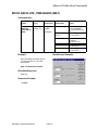
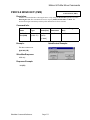
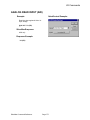
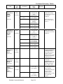
Read Internal Status Word (RIS)
Description:
The Internal Status Word is used in SilverMax to keep track of different conditions that are
present in the motor. This word may need to be read if more information on the motor status
is required. For example: Over and Under Voltage conditions can be checked when, for some
reason, the motor shuts down during operation. This gives the system greater knowledge
about the reasons for a shut down. The Internal Status Word can be cleared using the Clear
Internal Status command.
Command Info:
Command Name
Read Internal
Status Word (RIS)
Command Type
Immediate
(Class “A”)
Command
Code (Hex)
Command
Parameters
20
(0x14)
NONE
Parameter
Range
(Hex)
NONE
QuickControl Example:
Example:
Immediate (Host) Mode Command Only
Read back the Internal Status
Word
@16 20 (CR)
SilverMax Response:
State Code 2 Bytes
Response
Example:
Indicates Input #1, 2, 3 “High” ,
Last Calculation was Zero and
Index Sensor was found.
# 10 0014 00F3 (CR)
Table Showing the Bit definitions for the Internal Status Word (ISW)
Nibbles Latched
“0”
Bit #
Bit 15
ISW bit # 15-8
definitions
reserved
Nibbles
Bit #
Latched
ISW bit # 0-7 definitions
Bit 7
Yes
Bit
Bit
Bit
Bit
6
5
4
3
No
No
No
Yes
Over temperature
(“0” = True )
I/O #3
I/O #2
I/O #1
Negative Calculation result
Bit 2
Yes
Positive Calculation result
Bit 1
Bit 0
Yes
Yes
Zero Calculation result
Index sensor found
“F”
“0”
Yes
Yes
No
Yes
Bit 14
Bit 13
Bit 12
Bit 11
Yes
Bit 10
Yes
Yes
Bit 9
Bit 8
Low voltage
Over voltage
Wait Delay exhausted
Input found on last
move
Halt command was
sent
Holding error
Moving error
SilverMax Command Reference
“3”
Page 21
Status Commands
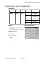
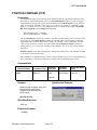
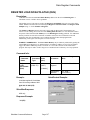
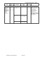
Read Program Buffer (RPB)
Description:
Reads the Data that is currently contained in the Program Buffer. The specified number of
Words is read from the Program Buffer starting with the given address. Up to 8 words can
be read at one time. This limit is due to the size restriction of the Serial Communications
Buffer. To read the entire contents of the Program Buffer multiple reads are required. For
details on SilverMax memory management, see the User Manual section Programming
SilverMax.
NOTE: When reading command codes from Program Buffer the MSB will be stripped off.
For example, if an MRV command is read from the Program Buffer, it will be read as a 0x07
instead of a 0x87.
Command Info:
Command Name
Read Program
Buffer (RPB)
Command Name
Command
Code (Hex)
Command
Parameters
Immediate
(Class “A”)
6
(0x6)
< Length >
(in words)
< Address >
QuickControl Example:
Example:
Read the first 7 words from Program Buffer
Immediate (Host) Mode Command Only
@16 6 7 0 (CR)
SilverMax Response:
Buffer Data “Length” of Words
Response Example:
# 10 0006 0007 0000 9C40 0002 7524 2000 0058 (CR)
SilverMax Command Reference
Parameter
Range
(Hex)
1 to 8
(1 to 0x08)
0 to 199
(0 to 0x00C7)
Page 22
Status Commands
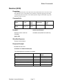
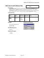
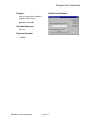
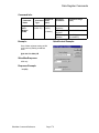
Revision (RVN)
Description:
This command returns the revision date of this code, and the buffer sizes. The code revision
date and buffer sizes of a SilverMax can be read back so that future upgrades can be dealt
with through a software interface. This enables dynamic changes in SilverMax usage when
different versions are used.
Command Info:
Command
Name
Revision
(RVN)
Command
Type
Immediate
(Class “A”)
Command
Code
(Hex)
5
(0x05)
Command
Parameters
NONE
Parameter
Range
(Hex)
NONE
QuickControl Example:
Example:
Immediate (Host) Mode Command Only
Read the revision code from
SilverMax
@16 5 (CR)
SilverMax Response:
Revision Code (8 Bytes)
Response Example:
SilverMax Revision code
# 10 0005 1116 1998 0108 0A34 (CR)
The following Revision information is available
Data Type
Data Format
A. Month
1 Byte
Example Shown
above
“11” = November
B. Day
1 Byte
“16” = 16th day
C. Year
2 Bytes
“1998” = The year 1998
D. Options Number
2 Bytes
“0108” = Code rev 108
E. Serial Communications Buffer Size
1 Byte
“0A” = 10 Words
F. Program Buffer Size
1 Byte
“34” = 52 Words
SilverMax Command Reference
Page 23
Override Commands
Override Commands
SilverMax Command Reference
Page 24
Override Commands
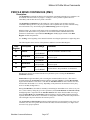
Halt (HLT)
Description:
This command immediately shuts down any motion in progress (hard stop), disables the single step
mode, and then causes the motor to load and run the Kill Recovery sequence.
This command stops the execution of all commands, programs and motions. When executed, it will
stop any command or program in process. Unless the Kill Recovery Routine has been designated and
the Kill Enable Driver has been enabled, the motor driver will be disabled. . This removes the drive to
the motor and allows the motor shaft to spin freely. After this, the KILL MOTOR RECOVERY
routine is called which allows the user to choose the recovery method. Running either the ENABLE
MOTOR DRIVER command or re-initializing the MOTOR CONSTANTS (for earlier revisions)
will put the motor back into position holding mode. Before doing this, the SET TARGET TO
POSITION command should be issued to avoid sudden extreme movement of the motor.
Bit #10 of the Internal Status Word is “set” to indicate that a Halt command was sent. This is useful
for determining the cause of the motor shut down when using an internal “Kill Recovery Program”.
Command Info:
Command
Name
Command
Type
Halt (HLT)
Immediate
(Class “A”)
Example:
Halt any Command, Program or
Motion in process
Command
Code
(Hex)
2
(0x2)
NONE
Parameter
Range
(Hex)
NONE
QuickControl Example:
Immediate (Host) Mode Command Only
@16 2 (CR)
SilverMax Response:
ACK only
Response Example:
Standard SilverMax Acknowledge
* 10 (CR)
SilverMax Command Reference
Command
Parameters
Page 25
Override Commands
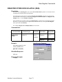
Restart (RST)
Description:
The Restart command is provided to cause the unit to do a “Hard” reset of the processor and logic
circuits. This causes the processor to jump to memory address zero as if the power were just cycled on.
If this command does not function, then the SilverMax unit will require a full power down and up to
reset the processor. All configurations and settings are returned to power-up defaults. Non-Volatile
memory is not affected.
Command Info:
Command
Name
Stop (STP)
Command
Type
Immediate
(Class “A”)
Command
Code
(Hex)
4
(0x4)
Example:
Reset the SilverMax processor. This
is done immediately with no
response to the command
Parameter Range
(Hex)
NONE
NONE
QuickControl Example:
Immediate (Host) Mode Command Only
@16 4 (CR)
SilverMax Response:
No Response
Response Example:)
THERE IS NO RESPONSE DUE
TO THE RESETTING OF THE
PROCESSOR
SilverMax Command Reference
Command
Parameters
Page 26
Override Commands
Single Step Exit (SSE)
Description:
This command causes the SilverMax to Exit the single step program execution mode. When SilverMax
has been placed into single step mode using the Single Step Program command this command takes
SilverMax out of the single step mode and restores normal execution. If the program is not at its end, it
will continue to execute until the end is reached. The Halt, Stop, Kill Motor, Power Low will also
exit the single step mode and halt the program execution.
Command Info:
Command
Name
Command
Type
Command
Code (Hex)
Command
Parameters
Parameter Range
(Hex)
Single
Step Exit
(SSE)
Immediate
(Class “C”)
18
(0x12)
NONE
NONE
Example
Exit Program single step mode.
QuickControl Example:
Immediate (Host) Mode Command Only
@16 18 (CR)
SilverMax Response:s
ACK only
Response Example
Standard SilverMax Acknowledge
* 10 (CR)
SilverMax Command Reference
Page 27
Override Commands
Single Step Program (SSP)
Description:
Puts SilverMax into a program single step mode and executes the first command in the program or
executes the next line in a program if already in single step mode. This command is used to step
through a program that has been downloaded into the Program Buffer. Issuing this command will
cause the next Program Type command to execute, then stop and wait for the next Single Step
Program command.
If a program has previously been loaded into the Program Buffer either by using the Load Program
command or by downloading from the Host, the Run Program must first be issued before the Single
Step Program has effect.
A Single Step Program command can be issued before a program is loaded. This puts SilverMax into
the Single Step mode that will wait until a program is loaded and then pause. When a Load and Run
Program command is used, the first command of the program will not be executed. This is because
the Load and Run Program command is a Program Type and acts like the first command in the
program.
Command Info:
Command
Name
Command
Type
Single Step
Program
(SSP)
Immediate
(Class “C”)
Command
Code
(Hex)
17
(0x11)
Example:
Put SilverMax into Single Step
Program mode or Step the program.
Parameter Range
(Hex)
NONE
NONE
QuickControl Example:
Immediate (Host) Mode Command Only
@16 17 (CR)
SilverMax Response:
ACK only
Response Example:
Standard SilverMax Acknowledge
* 10 (CR)
SilverMax Command Reference
Command
Parameters
Page 28
Override Commands
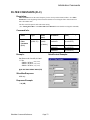
Stop (STP)
Description:
The Stop command exits the executing program or motion and goes into Hold. If a motion is running,
the Deceleration parameter sets the deceleration as follows: If “0”, it uses the executing command’s
acceleration value for deceleration. If this value is positive, it uses the given deceleration value. If the
deceleration parameter is negative, the unit does an immediate stop (directly to Hold). The Target
value is set to the present position. If the unit is not executing a motion, any Program type command
executing is terminated and the unit returns to idle.
When the Stop command is sent the Program Buffer is over-written (similar to a Clear Buffer). The
Program Buffer must be loaded again (Load Program or Load and Run Program) for Program
execution.
Command Info:
Command
Name
Command
Type
Stop (STP)
Immediate
(Class “A”)
Command
Code
(Hex)
3
(0x3)
Parameter Range
(Hex)
<<Deceleration>>
-1 = Stop Immediate
or
0 = Stop using
previous
Acceleration
or
1 to 536,870,911
(1 to 0x1FFFFFFF)
QuickControl Example:
Example:
Immediate (Host) Mode Command
Only
Stop the SilverMax using the previous
command Acceleration parameter
@16 3 0 (CR)
SilverMax Response:
ACK only
Response Example:
* 10 (CR)
SilverMax Command Reference
Command
Parameters
Page 29
Initialization Commands
Initialization Commands
SilverMax Command Reference
Page 30
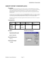
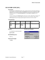
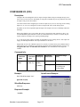
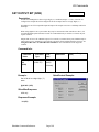
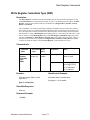
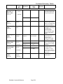
Initialization Commands
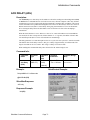
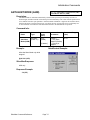
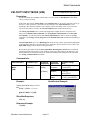
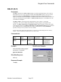
ACK DELAY (ADL)
Description:
The ACK Delay sets a time delay for SilverMax to wait before sending an Acknowledgement (ACK)
or DATA after a command has been received. In some cases, the host computer or PLC may not have
enough time to set up for reception after having transmitted a command. The ACK Delay can be used
to have SilverMax wait a predetermined length of time to allow for these delays. In the case where an
RS-485 network in used, there is often a delay when going from transmit to receive for the RS-485
driver. Setting the delay allows the SilverMax to wait for the line to be free before attempting a
transmission.
When the Serial interface is set to “RS-232” a value of “0” causes SilverMax to run in standard RS232 mode (the Tx line is always driven). With a number of “1” or greater, SilverMax will run in RS232 multi-drop mode (the Tx line is tri-stated when not transmitting).
The delay parameter is a count that equates to the servo cycle tick. One cycle tick is 120 microseconds.
The default value for the delay count is 4, this gives a delay of approximately 0.5 milliseconds. The
largest count that can be set is 21845 - this will give a delay of 2.6214 seconds.
When sending this command the delay takes effect before the Acknowledge is sent.
Command Info:
Command
Name
Ack Delay
(ADL)
Command
Type
Program
(Class “D”)
Example:
Command
Code
(Hex)
173
(0xAD)
Parameter Range
(Hex)
<Count in Ticks>
1 Tick = 120usec.
0 to 21845
(0 to 0x5555)
[2 Words]
QuickControl Example:
Delay ACK for 2.5 milliseconds
@16 173 20 (CR)
SilverMax Response:
ACK only
Response Example:
* 10 (CR)
SilverMax Command Reference
Command
Parameters
Page 31
Initialization Commands
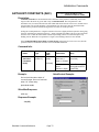
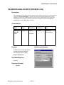
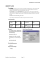
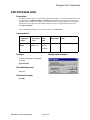
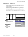
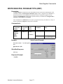
ANTI-HUNT CONSTANTS (AHC)
See Also: TORQUE LIMITS (TQL),
ANTI-HUNT DELAY (AHD)
Description:
Anti-Hunt Constants set the thresholds used to determine if the position is sufficiently close to the
target to allow the motor to go into and to stay in Anti-hunt mode. The first parameter is the
maximum error (in counts) allowed in the Anti-Hunt mode before the unit will revert to normal closed
loop operation. The second parameter is the maximum error allowed to enter the Anti-Hunt mode.
Neither of these parameters should be larger than 30 counts for normal operation.
Setting the second parameter to a negative number will cause a slightly different operation when going
from No Anti-Hunt into Anti-Hunt (Closed => Open). Normally SilverMax will not go into Anti-Hunt
until the error is within the limit and the Closed Loop holding current is less than the Open Loop
holding current. When the error parameter is negative, the Holding currents are not checked.
If the TORQUE LIMITS Open Hold and Open Moving parameters have been set to zero, then the
parameters in this command set the limits of a conventional dead-band.
Command Info:
Command
Name
Anti-Hunt
Constants
(AHC)
Command
Type
Program
(Class “D”)
Command
Code
(Hex)
150
(0x96)
[3 Words]
Example:
Parameter Range
(Hex)
< Out of AntiHunt error >
Open => Closed
0 to 35
(0 to 0x23)
< Into Anti -Hunt
error>
Closed => Open
-35 to 35
(0 to 0x35 & 0xFFFF
to 0xFFDD)
QuickControl Example:
Go into Anti-Hunt when within “4”
counts of target. Go out of Anti-Hunt
when “10” counts away
@16 150 10 4 (CR)
SilverMax Response:
ACK only
Response Example:
*10 (CR)
SilverMax Command Reference
Command
Parameters
Page 32
Initialization Commands
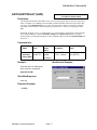
ANTI-HUNT DELAY (AHD)
See Also: ANTI-HUNT CONSTANTS (AHC)
ANTI-HUNT MODE (AHM)
Description:
The Anti-Hunt mode allows SilverMax to move from closed loop operation to open loop operation in
order to eliminate servo dithering. The Anti-Hunt Constants determine when, based on position, this
will occur. The Anti-Hunt Delay sets up a time delay from when a motion is complete to when the
Anti-Hunt is allowed. This is useful for allowing a system time to “settle” prior to going into AntiHunt.
By default, the delay is set to “0”. Settling time is a system parameter, which must be analyzed under
real working conditions. Using the SilverMax Tuning tool in QuickControl allows viewing of
motion profiles for analyzing settling times. This command is ignored when the Anti-Hunt Mode has
been set to 1.
Command Info:
Command
Name
Anti-Hunt
Delay (AHD)
Command
Type
Program
(Class “D”)
Example:
Command
Code
(Hex)
230
(0xE6)
Parameter Range
(Hex)
< Count in Ticks >
1 Tick = 120usec.
0 to 65535
(0 to 0xFFFF)
[2 Words]
QuickControl Example:
Allow Anti-Hunt 10 milliseconds
after a motion is completed.
@16 230 83 (CR)
SilverMax Response:
ACK only
Response Example:
* 10 (CR)
SilverMax Command Reference
Command
Parameters
Page 33
Initialization Commands
ANTI-HUNT MODE (AHM)
See Also: ANTI-HUNT CONSTANTS (AHC)
ANTI-HUNT DELAY (AHD)
Description:
The default mode of Anti-Hunt automatically switches from open loop to closed loop as soon as a
motion begins, and then remains in closed loop for Anti-Hunt Delay time counts after the position error
is less than the closed to open parameter. Anti-Hunt mode with Mode=1 bypasses the in motion check,
allowing the motor to remain in open loop, even while moving, as long as the error is sufficiently low.
A value of Mode=0 switches the Anti-Hunt function back to its default mode of operation.
Command Info:
Command
Name
Anti-Hunt
Mode (AHM)
Command
Type
Program
(Class “D”)
Example:
Command
Code
(Hex)
219
(0xDB)
[2 Words]
Parameter Range
(Hex)
< Mode >
0 = only when
stopped. (Default)
1 = moving or
stopped.
0 or 1
QuickControl Example:
Allow Anti-Hunt Mode only while
stopped.
@16 219 0 (CR)
SilverMax Response:
ACK only
Response Example:
*10 (CR)
SilverMax Command Reference
Command
Parameters
Page 34
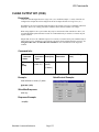
Initialization Commands
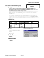
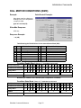
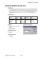
BAUD RATE (BRT)
Description:
If a Baud Rate different than the default rate is required, such as with a PLC limited to 9600 baud, the
Baud Rate command can be used to change the baud rate to a range of other values. The baud rate is
limited to a maximum value of 230400 bits per second. 57600 is the default baud at power up. Other
baud rates can be set using “Speed” values from the table below.
Command Info:
Command
Name
Command
Type
Baud Rate
(BRT)
Program
(Class “D”)
Command
Code
(Hex)
174
(0xAE)
[2 Words]
Example:
(8-Bit ASCII Protocol)
@16 174 576 (CR)
SilverMax Response:
ACK only
Data Format
(Hex)
NONE
Response Example:
*10 (CR)
NOTE: The baud rate changes
immediately, so, if different than
the current baud rate, the
Acknowledge may not be
intelligible.
SilverMax Command Reference
Parameter Range
(Hex)
< Speed>
3 = 300 (baud)
12 = 1200
24 = 2400
48 = 4800
96 = 9600
192 = 19200
288 = 28800
384 = 38400
576 = 57600
1000 =100000
1152 =115200
2304 =230400
QuickControl Example:
Set the baud rate for 57.6K. This
works with most PLCs.
Description
Command
Parameters
Page 35
Initialization Commands
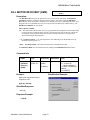
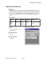
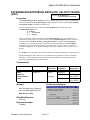
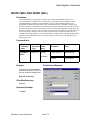
CALIBRATE ANALOG INPUT FROM NV (CAI)
Description:
This command loads the Analog Channel Calibration Factor and the Maximum over voltage shutdown
voltage from Non-Volatile Memory. This data for each unit is determined and stored in a factory
calibration procedure. The calibration data is stored as a long word into location 65524. The CAI
command must be executed before the motor parameters are loaded, and before setting the Low
Voltage Trip or Over Voltage Trip commands.
Command Info:
Command
Name
Command
Type
Command
Code (Hex)
Command
Parameters
Parameter Range
(Hex)
Calibrate
Analog Input
From Nv
(CAI)
Program
(Class “D”)
211
(0xD3)
<NV Memory
Address>
Factory Default
Calibration =
65524 (0xFFF4)
[2 Words]
Example:
QuickControl Example:
Calibrates the Power Supply analog
channel and sets the maximum
overvoltage shutdown voltage.
@16 211 65524 (CR)
SilverMax Response:
ACK only
Response Example:
*10 (CR)
SilverMax Command Reference
Page 36
Initialization Commands
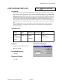
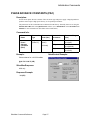
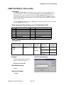
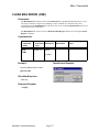
CONTROL CONSTANTS (CTC)
See Also: FILTER CONSTANTS (FLC)
Description:
This command sets the various servo loop gain control constants. These are used in tuning the motor.
Gain term List Velocity #1 Feedback : Single filtered velocity feedback term
Velocity #2 Feedback : Double filtered velocity feedback term
Velocity Feedfoward: Velocity feedforward term
Acceleration Feedback: Acceleration estimator feedback term
Acceleration Feedforward: Acceleration feedforward term
Proportional: Position error feedback term
Integrator: Integration of the error feedback term summed with the three velocity terms.
(See “Tuning SilverMax” in the SilverMax User Manual for more details.)
Command Info:
Command
Name
Control
Constants
(CTC)
Command
Type
Command
Code (Hex)
Command
Parameters
Parameter Range
(Hex)
Program
(Class “D”)
148
(0x94)
<Velocity 1
Feedback Gain>
0 to 32767
(0 to 0x7FFF)
[8 Words]
<Velocity 2
Feedback Gain>
0 to 32767
(0 to 0x7FFF)
<Velocity
Feedfoward Gain>
0 to 32767
(0 to 0x7FFF)
<Acceleration
Feedback Gain>
0 to 32767
(0 to 0x7FFF)
<Acceleration
Feedfoward Gain>
0 to 32767
(0 to 0x7FFF)
<Proportional
Gain>
0 to 32767
(0 to 0x7FFF)
<Integrator Gain>
0 to 32767
(0 to 0x7FFF)
Example:
QuickControl Example:
@16 148 0 10 10 10 10 200 1000
(CR)
SilverMax Response:
ACK only
Response Example:
*10 (CR)
SilverMax Command Reference
Page 37
Initialization Commands
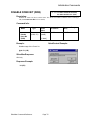
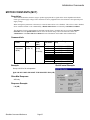
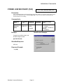
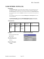
DISABLE DONE BIT (DDB)
See Also: ENABLE DONE HIGH (EDH)
ENABLE DONE LOW (EDL)
Description:
Disables the “Done” bit (I/O #1) on the motor. The “Done” bit indicates when the motor is running or
idle (See Enable Done Bit for more details)
Command Info:
Command
Name
Disable
Done Bit
(DDB)
Command
Type
Program
(Class “D”)
Example:
Command
Code
(Hex)
171
(0xAB)
Parameter Range
(Hex)
NONE
NONE
[1 Word]
QuickControl Example:
Disable usage of the “Done” bit
@16 171 (CR)
SilverMax Response:
ACK only
Response Example:
* 10 (CR)
SilverMax Command Reference
Command
Parameters
Page 38
Initialization Commands
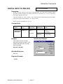
DIGITAL INPUT FILTER (DIF)
See Also: I/O Commands
Description:
Sets up a filter time constant for any of the seven digital inputs. A "0" in the I/O line parameter causes
all of the input filter constants to be changed at the same time. Selecting 1,2, 3, 4, 5, 6 or 7 for the I/O
line changes only the selected line.
The Filter constant is in "Ticks" (120 usec / tick). Setting the filter constant affects how long a digital
state must be held for the SilverMax to “see” the given state.
NOTE: At power-up all filters are set to "0".
Command Info:
Command
Name
Digital Input
Filter (DIF)
Command
Type
Command
Code (Hex)
Command
Parameters
Parameter Range
(Hex)
Program
(Class “D”)
252
(0xFC)
< I/O Line # >
[3 Words]
< Filter
Constant>
0 = All Lines
1 to 7
(0 to 0x7)
0 to 32767
(0 to 0x7FFF)
Example:
QuickControl Example:
Filter Input #1 so that it must be
either low or high for as least 117.96
milliseconds before the low or high
state is accepted.
@16 252 1 983 (CR)
SilverMax Response:
ACK only
Response Example:
* 10 (CR
SilverMax Command Reference
Page 39
Initialization Commands
DIRECTION (DIR)
Description:
Establishes at initialization the direction the motor will turn by using a positive or negative number.
Normally the SilverMax will turn Clockwise (when viewed from the shaft end of motor) when a
positive distance or velocity number is used. A negative number will cause the motor to turn counter
clockwise. Using the Direction command, this default operation can be reversed.
NOTE: This command can only be used when SilverMax is in the Open Loop mode and should be set
during the power up initialization process of SilverMax before the initial torque command.
Command Info:
Command
Name
Direction
(DIR)
Command
Type
Program
(Class “D”)
Example:
Command
Code
(Hex)
184
(0xB8)
Parameter Range
(Hex)
<Selection>
0 = Normal (CW)
1 = Reverse
[2 Words]
QuickControl Example:
Clockwise
@16 184 0 (CR)
SilverMax Response:
ACK only
Response Example:
* 10 (CR
SilverMax Command Reference
Command
Parameters
Page 40
Initialization Commands
DUAL LOOP CONTROL (DLC)
See Also: SELECT EXTERNAL ENCODER
(SEE), SINGLE LOOP CONTROL
(SLC)
Description:
Configures SilverMax to run in a Dual Loop control mode. In Dual Loop Control, the SilverMax
servos its position based on an External Encoder signal. SilverMax commutation, velocity and
acceleration feedback information is derived from the Internal Encoder. Moving and Holding error
limits also use the External Encoder for the Kill Motor Conditions.
The Anti-Hunt mode uses the Position Error derived from the External Encoder to establish when to
move in and out of Anti-Hunt mode. The ANTI-HUNT CONSTANTS “Closed => Open”
parameter should be set to “1” so that an error of “0” will allow entry into Anti-Hunt.
When position control of the driven device is needed, this command along with an External Encoder
connected to the device, will enable direct position control of the device. When using a linear slider, a
linear encoder can be used for the External Encoder signal.
When entering dual loop control SilverMax sets the current “Target” to the “Current position”
(External Position) to prevent a sudden motion.
SilverMax must be in Closed Loop Mode for this command to take effect.
By default, SilverMax starts up in Single Loop Control mode. The Dual Loop Control command can
be placed within a User Program to place the motor properly into Dual Loop Control. Use of a single
loop move prior to entering dual loop move may be used to verify that the external encoder is
connected and operational.
The External Encoder settings should be initialized prior to using this command or unpredictable
results may occur. Use the Select External Encoder command to set up the external encoder usage.
NOTE: The Control Constants typically need to be configured differently for single loop operation
than for dual loop operation. The Velocity and Acceleration parameters for motions become related to
external encoder counts rather than internal encoder units. The feedforward acceleration and velocity
terms are relative to full speed in external encoder units while the feedback terms are relative to the
internal encoder units, thus the feedback terms may need to be different from the feedfoward terms in
order to minimize following error. If the external encoder has three times the resolution of the internal
encoder, then the feedback terms need to be three times as large as the feedforward terms to balance
their gains.
Command Info:
Command
Name
Dual Loop
Control
(DLC)
Command
Type
Program
(Class “D”)
SilverMax Command Reference
Command
Code
(Hex)
243
(0xF3)
[1 Word]
Page 41
Command
Parameters
Parameter Range
(Hex)
NONE
NONE
Initialization Commands
Example:
QuickControl Example:
Configure SilverMax for Dual Loop
Control
@16 243 (CR)
SilverMax Response:
ACK only
Response Example:
* 10 (CR
SilverMax Command Reference
Page 42
Initialization Commands
DISABLE MOTOR DRIVER (DMD)
See Also: ENABLE MOTOR DRIVER
(EMD)
Description:
Disables the motor driver and shorts the windings together. The SilverMax will be unable to move
when attempting any motion command. This is a software disable that can be overcome by the Enable
Motor Driver command, or by setting the Motor Constants.
Command Info:
Command
Name
Disable
Motor
Driver
(DMD)
Command
Type
Program
(Class “D”)
Command
Code
(Hex)
228
(0xE4)
Parameter Range
(Hex)
NONE
NONE
[1 Word]
Example:
QuickControl Example:
Disable the Motor Driver electronics
@16 228 (CR)
SilverMax Response:
ACK only
Response Example:
* 10 (CR)
SilverMax Command Reference
Command
Parameters
Page 43
Initialization Commands
DISABLE MULTI-TASKING (DMT)
See Also: ENABLE MULTI-TASKING
(EMT)
Description:
Disables SilverMax Multi-Tasking operation. SilverMax executes Programs in a sequential manner by
executing each command until completion before moving to the next. See Enable Multi-Tasking for
more information on Multi-Tasking operation. If a motion is active, the next program line will not be
executed until the motion has completed.
Command Info:
Command
Name
Disable
MultiTasking
(DMT)
Command
Type
Program
(Class “D”)
Command
Code
(Hex)
226
(0xE2)
Parameter Range
(Hex)
NONE
NONE
[1 Word]
Example:
QuickControl Example:
Disable the Multi-Tasking operation
@16 226 (CR)
SilverMax Response:
ACK only
Response Example:
* 10 (CR)
SilverMax Command Reference
Command
Parameters
Page 44
Initialization Commands
ENABLE DONE HIGH (EDH)
See Also: DISABLE DONE BIT (DDB)
ENABLE DONE LOW (EDL)
Description:
Enables a “Done” indication on the motor I/O Line #1. The “Done” indicates when the motor is idle
and within the set Error Limits. When the motor is idle (Hold mode) the Done indicator will be High
(“1”). During the execution of a motion profile command the Done indicator will go Low (“0”)
indicating the motor is moving. It will then go high at the end of the motion.
If the motor position during the move or when holding exceeds the error limits, the bit will go low or
remain Low even when a motion completes.
PLCs or Host Controllers can use the “Done” indication for monitoring SilverMax motions to check
for completion.
When in Step & Direction mode and no multi-tasking program is running, the “Done” only indicates
position errors.
Command Info:
Command
Name
Enable
Done High
(EDH)
Command
Type
Program
(Class “D”)
Command
Code
(Hex)
251
(0xFB)
Parameter Range
(Hex)
NONE
NONE
[1 Word]
Example:
QuickControl Example:
Enable usage of the “Done”
indication by setting I/O line #1 High
@16 251 (CR)
SilverMax Response:
ACK only
Response Example:
* 10 (CR)
SilverMax Command Reference
Command
Parameters
Page 45
Initialization Commands
ENABLE DONE LOW (EDL)
See Also: DISABLE DONE BIT (DDB)
ENABLE DONE HIGH (EDH)
Description:
Enables a “Done” indication on the motor I/O Line #1. The “Done” indicates when the motor is idle
and within the set Error Limits. When the motor is idle (Hold mode) the Done indicator will be Low
(“0”). During the execution of a motion profile command the done indicator will go High (“1”)
indicating the motor is moving. It will then go low at the end of the motion.
If the motor position during the move or when holding exceeds the error limits, the bit will go high or
remain High even when a motion completes.
PLCs or Host Controllers can use the “Done” indication for monitoring SilverMax motions to check
for completion.
When in Step & Direction mode and no multitasking program is running, the “Done” only indicates
position errors.
Command Info:
Command
Name
Enable
Done Low
(EDL)
Command
Type
Program
(Class “D”)
Command
Code
(Hex)
187
(0xBB)
Parameter Range
(Hex)
NONE
NONE
[1 Word]
Example:
QuickControl Example:
Enable usage of the “Done”
indication by setting I/O line #1 Low
@16 187 (CR)
SilverMax Response:
ACK only
Response Example:
* 10 (CR)
SilverMax Command Reference
Command
Parameters
Page 46
Initialization Commands
ENABLE MOTOR DRIVER (EMD)
See Also: DISABLE MOTOR DRIVER
(DMD)
Description:
Enables the SilverMax motor driver. The driver is by default enabled, this command is only required if
the driver has been disabled using the Disable Motor Driver command or disabled by the Kill Motor
operation or by an over voltage condition.
Command Info:
Command
Name
Enable
Motor
Driver
(EMD)
Command
Type
Program
(Class “D”)
Command
Code
(Hex)
227
(0xE3)
Parameter Range
(Hex)
NONE
NONE
[1 Word]
Example:
QuickControl
Example:
Enable the SilverMax motor driver
@16 227 (CR)
SilverMax Response:
ACK only
Response Example:
* 10 (CR)
SilverMax Command Reference
Command
Parameters
Page 47
Initialization Commands
ENABLE MULTI-TASKING (EMT)
See Also: DISABLE MULTI-TASKING
(DMT)
Description:
Enables SilverMax “Multi-Tasking” operation, which allows Motion while executing a program. By
default, SilverMax does not continue internal program execution when performing a motion command
or while executing in a Velocity Mode, Step and Direction Mode or Input Mode. Enable MultiTasking causes SilverMax to continue program execution after a motion command or mode has been
started.
Multi-Tasking is useful for conditions where the SilverMax is acting as a Master controller and must
initiate other tasks while performing motions. An example of this is performing I/O operations for
controlling other machine functions. SilverMax will be able to “Set” or “Clear” the I/O lines at any
time. Many other things can be done including modifying motion profiles on-the-fly when executing a
Profile Move command or the Register Step and Direction command.
Multi-Tasking rules of engagement when enabled:
Time and Velocity based motion commands (Absolute or Relative, Direct or Register-based):
These commands start by loading the move parameters into the “Calculation task”, and wait until the
calculation is done (to check for errors) before turning it over to the Trajectory Generator. The next
command in the Command Buffer may not proceed until the pre-move calculation has completed (1.5
milliseconds). If the next command is a Motion command and the previous motion command is still
active, a “Busy” state will occur that will cause a “Wait” for the prior motion to complete before
starting. This acts to buffer the second motion command and will cause the program to hold until the
second motion command has completed its Calculation Task. No error is generated.
NOTE: Step and Direction Mode, Velocity Mode, Input Mode or a Profile Move is NOT
terminated by a Motion command when in Multi-Tasking operation. These other modes or
operations must be explicitly terminated or completed before a move is initiated.
Velocity Mode command: This command does not check the “Busy” status when executed. It just
jumps in and takes over from wherever a motion is executing. The Step and Direction Mode, Input
Modes or a Profile Move can be taken over by the Velocity Mode. Velocity Mode can be used to
decelerate from any of these operations to a stop using a given deceleration.
Profiled Move Override: This command does not check the “Busy” status when executed. It starts up
with the existing position and velocity and continues from there applying the new parameters. It can be
used to take over any existing motion.
Profiled Move Exit: This command does not check the “Busy” status. It uses the Profiled
Deceleration parameter to bring any current motion to a stop.
Target Offset command: This command may be used to offset the current value of the Trajectory
Generator (hopefully a little at a time), even while other motions or modes are running. When in
Multi-Tasking this could facilitate a skew forward or skew back while in the Step and Direction
Mode. This command only affects the Target, and thus does not affect open loop operation.
Step and Direction commands: These commands can only be over-written by another Step and
Direction command, Velocity Mode command, Hard Stop Move command, Profiled Move
Override command or Profiled Move Exit command. After the commands have executed (done in
one time slice), the program moves to the next command in the Command Buffer. When MultiTasking is disabled program execution halts at these commands until a stop condition occurs.
NOTE: The Registered Step and Direction command has another benefit in that the scaling value,
stored in a User Data Register, may be dynamically modified with continuing program
SilverMax Command Reference
Page 48
Initialization Commands
statements to implement ramp-up, ramp-down and synchronization functions. (See Registered
Step and Direction command for more information)
(Continued on next page)
Input Mode commands: The mode parameters, contained in User Data Registers 12 – 18, may be
dynamically modified, using the Write Register commands , in continuing program statements while
operating in the any of the Input Modes.
Profile Move commands: These commands can only be over-written by a Profile Move Override
command, the Profile Move Exit command or by the Velocity Mode. They operate using User Data
Registers for the motion parameters. The Data Registers can be updated at any time from a Host
controller using the serial interface. This can be done regardless of the Multi-Tasking state. If however,
an internal program is used to modify the Data Registers, Multi-Tasking must be enabled. After a
Profile Move command is executed, continuing program statements may be used to dynamically
modify the Data Registers. (See Profile Move commands for more information on usage.)
Program End command: If multitasking is enabled, and this command is encountered the executing
program exits and the Program Complete status bit is set in the Polling Status Word. If there is an
active motion command, it will continue execution until complete; (delayed until motions or modes
have completed if not set for Multi-Tasking operation); when this motion or mode completes, status bit
15 (foreground complete) in the Polling Status Word is set.
Halt command: Runs the Kill Recovery command after setting the Halt bit in the Internal Status
Word. The current motion or mode is terminated. The motor driver will remain “enabled” if the Kill
Enable Driver command has been issued. Without Multi-Tasking, the motor driver is always
disabled regardless of the Enable Driver state.
Command Info:
Command
Name
Enable
MultiTasking
(EMT)
Command
Type
Command
Code (Hex)
Command
Parameters
Parameter Range
(Hex)
Program
(Class “D”)
225
(0xE1)
NONE
NONE
Example:
[1 Word]
QuickControl Example:
Enable Multi-Tasking operation
@16 225 (CR)
SilverMax Response:
ACK only
Response Example:
* 10 (CR)
SilverMax Command Reference
Page 49
Initialization Commands
ERROR LIMITS (ERL)
See Also: KILL MOTOR CONDITIONS
(KMC)
Description:
Error Limits sets the Moving Error limits, the Holding Error limits, and the Delay to Hold time
following a motion before the motor uses the holding torque limit setting and the holding error limits.
At the completion of a motion (the Trajectory Generator has completed the move calculation), the
Delay to Holding counter will begin counting down. When the count reaches zero (one count per 120
microseconds), the motor changes to Hold Mode. The Moving Error limit is always checked, while
the Holding Error limit is only checked while in the Hold Mode.
The Delay to Holding also controls when the SilverMax will switch from the Moving torque limits to
the Holding torque limits. Lower closed holding torques may be used to reduce heating in the case of a
stall or jam. Reduced open holding torques may be used to reduce heating when in anti-hunt mode.
Error conditions are set in both the Internal Status Word and in the Polling Status Word if the error
limits are exceeded. The Polling Status Word error condition can alert the Host controller to the
condition if the unit is being polled. The conditions in the Internal Status Word may be used to halt
the motor in the case of a motion error. (See the Kill Motor command for more information on halting
a motor.)
A special “Drag” mode may be implemented by setting the error limits to negative values. The
absolute value of the limit is used to generate the status conditions, while the Target is not allowed to
get farther than the respective error limit from the motor position. This can be used to set up a “clutch”
mode where the output shaft can be dragged around to a desired position and the system will then
maintain that position. This is useful for some mechanical alignment procedures, as well as for
implementing drag clutch operations. Combining the Drag mode with the Profiled Move commands
allows obstructions or other torque limited operation to recover while maintaining the requested
velocity when the obstruction is removed. The Profiled Moves will continue to the requested position
even if the drag mode is engaged. The Kill Motor Conditions should not be enabled if using this
mode (The motor will shut down).
Command Info:
Command
Name
Error Limits
(ERL)
Command
Type
Program
(Class “D”)
Command
Code
(Hex)
151
(0x97)
[4 Words]
Command
Parameters
Parameter Range
(Hex)
< Moving limit >
-32768 to 32767
(0 to 0xFFFF)
< Holding limit >
-32768 to 32767
(0 to 0xFFFF)
0 to 65535
(0 to FFFF)
< Delay to Holding >
(1 tick = 120usec.)
SilverMax Command Reference
Page 50
Initialization Commands
Example:
QuickControl Example:
Allow 500 counts of error while
moving and 100 counts of error
when holding position. Allow 120
milliseconds before going into Hold
mode with its tighter error limit.
@16 151 500 100 1000 (CR)
SilverMax Response:
ACK only
Response Example:
* 10 (CR)
SilverMax Command Reference
Page 51
Initialization Commands
FILTER CONSTANTS (FLC)
Description:
Filter Constants selects the cutoff frequency for the velocity and acceleration filters. See “Filter
Parameters” in the beginning of this manual for details on converting the filter values from Hz to
native SilverMax units.
The filter cutoff frequencies affect the motor tuning.
(See “Tuning SilverMax” in the SilverMax User Manual for more details on using this command.)
Command Info:
Command
Name
Filter
Constants
(FLC)
Command
Type
Program
(Class “D”)
Command
Code
(Hex)
169
(0xA9)
Command
Parameters
Parameter Range
(Hex)
< Velocity 1
Feedback >
0 to 32767
(0 to 0x7FFF)
[4 Words]
< Velocity 2
Feedback >
< Acceleration
Feedback >
0 to 32767
(0 to 0x7FFF)
0 to 32767
(0 to 0x7FFF)
Example:
QuickControl Example:
Set filters to roll of at 469, 413 and
117 Hz.
23000 = 32768 e- (469)2π(120uS)
24000 = 32768 e- (413)2π(120uS)
30000 = 32768 e- (117)2π(120uS)
@16 169 23000 24000 30000 (CR)
SilverMax Response:
ACK only
Response Example:
* 10 (CR)
SilverMax Command Reference
Page 52
Initialization Commands
GRAVITY OFFSET CONSTANTS (GOC)
Description:
Establishes a value that compensates for the effects of gravity on the load that the motor is driving.
This servo control parameter is designed to neutralize the effect of gravity on mechanisms that operate
in other than horizontal orientation. It enables the servo control to operate consistently in both
directions of motor rotation by creating a Torque offset that counters the torque required to hold the
load in position.
The offset value is in torque units the same as the Torque Limits command. If, for example, it requires
¼ of the motor’s torque capability to hold the load in position, the value may be set to approximately ¼
of the 100% torque value. (If the full torque value were 20000, the ¼ value would be 5000)
Depending on the direction of the Torque applied to the motor shaft, the value can be set to a negative
or positive value.
Command Info:
Command
Name
Gravity
Offset
Constant
(GOC)
Command
Type
Command
Code (Hex)
Command
Parameters
Parameter Range
(Hex)
Program
(Class “D”)
237
(0xED)
< Gravity Offset >
-32767 to 32767
(0 to 0x7FFF)
Example:
[2 Words]
QuickControl Example:
Set the Gravity Offset to 35%
Torque for a QCI-23-3 motor
@16 237 7000 (CR)
SilverMax Response:
ACK only
Response Example:
* 10 (CR)
SilverMax Command Reference
Page 53
Initialization Commands
IDENTITY (IDT)
Description:
The Identity command is used to select the Unit ID and Group ID addresses to which the SilverMax
will respond. The SilverMax will accept and respond to any command addressed with the Unit
identifier. The SilverMax will accept commands sent to either the
Group Identifier or to the Global Identifier (255), but no response will be sent as multiple units
cannot respond at the same instant. No two units should have the same Unit identity when connected
on the same network. Multiple units may share a common Group identity when they are on the same
network.
Identities need to be in the range of 1 to 254.
Upon issuing this command, the SilverMax will respond with the new identifier.
Command Info:
Command
Name
Identity
(IDT)
Command
Type
Program
(Class “D”)
Command
Code
(Hex)
155
(0x9B)
[2 Words]
Example:
Parameter Range
(Hex)
<Group + Unit
Identity>
Group = Upper Byte
Unit = Lower Byte
257 to 65278
(0x0101 to 0xFEFE)
QuickControl Example:
To Calculate number: Multiply the
Group Identity times 256, then add
the Unit Identity
Group = 10, Unit = 16
Identity = (10 * 256) + 16 = 2576
Group Identity of 10, Unit Identity of
16;
@16 155 2576 (CR)
SilverMax Response:
ACK only
Response Example:
* 10 (CR)
SilverMax Command Reference
Command
Parameters
Page 54
Initialization Commands
KILL DISABLE DRIVER (KDD)
See Also: KILL ENABLE DRIVER
(KED)
Description:
Disables the motor driver, shorting across the windings (passive braking) when a Kill Motor
Condition is met. If the SilverMax is moving, it will stop immediately in a rapid manner. The motor
will be unable to move until re-enabled using the Enable Motor Driver command. This is the default
setting for the motor.
Command Info:
Command
Name
Kill Disable
Driver
(KDD)
Command
Type
Command
Code (Hex)
Command
Parameters
Parameter Range
(Hex)
Program
(Class “D”)
183
(0XB7)
NONE
NONE
[1 Word]
Example:
QuickControl Example:
Disable the Motor Driver electronics
when Kill Motor Conditions are met
@16 183 (CR)
SilverMax Response:
ACK only
Response Example:
* 10 (CR)
SilverMax Command Reference
Page 55
Initialization Commands
See Also: KILL DISABLE DRIVER
(KDD), ENABLE MULTITASK (EMT)
KILL ENABLE DRIVER (KED)
Description:
Causes SilverMax to leave the motor drivers enabled when a Kill Motor Condition is met.
Normally the motor driver is disabled with a Kill Motor Condition, this command can be used to
leave the driver enabled if continuing operation is required.
In order for this command to function, SilverMax must be set up for Multi-Tasking operation (See
Enable Multi-Task). Without Multi-Tasking, the driver will be disabled when a Kill Motor
Condition occurs.
This command is very useful for times when a controlled shutdown of the motor is needed. For
example, if there is a need to slowly ramp down the speed of the motor a Velocity Mode, Program
Type command can be used in the Kill Recovery program to decelerate to zero speed with the given
deceleration.
Command Info:
Command
Name
Kill Enable
Driver
(KED)
Command
Type
Command
Code (Hex)
Command
Parameters
Parameter Range
(Hex)
Program
(Class “D”)
182
(0xB6)
NONE
NONE
Example:
[1 Word]
QuickControl Example:
Leave the SilverMax motor driver
enabled
@16 182 (CR)
SilverMax Response:
ACK only
Response Example:
* 10 (CR)
SilverMax Command Reference
Page 56
Initialization Commands
KILL MOTOR CONDITIONS (KMC)
See Also: KILL MOTOR RECOVERY
(KMR)
Description:
The Kill Motor Conditions allows the user to select what conditions will allow a controlled shutdown
of the SilverMax unit. The Condition Enable word selects which bits in the Internal Status Word
will be evaluated. Conditions are enabled by setting a “1” in the desired bit position of the Condition
Enable binary word. The Condition State word allows the user to specify the state of the selected
conditions that will cause the motor to do a controlled shutdown. Normal usage will include the Over
Temperature state (Bit #7) in order to prevent unexpected motor restarts when the case temperature
has returned to allowable temperatures. Some users may use the Moving Error bit to shut down the
motor if the expected moving position error has been exceeded, as would be caused by a jam or
obstruction. Digital inputs can also be used to implement a shut down from “End of Travel” limits if
external switches are provided. Additionally, the Wait Delay function could be used as a watchdog
timer if the wait function were not needed within the user Program (writing the wait with the no delay
option would keep this number from expiring to zero). Note: Over-voltage is always enabled
whenever the driver is enabled to protect the drivers from over voltage. An over-voltage condition will
always disable the drivers regardless of the of Kill Enable Drivers state.
What Happens when the Kill Motor is tripped:
Bit 3 of the Status Word is set to indicate a shutdown.
If no Kill Motor Recovery routine has been designated by using the Kill Motor Recovery command,
then the motor drivers are disabled, and any running program and moves are terminated.
If a Kill Motor Recovery routine has been designated, the drivers will be disabled and the active
motion terminated unless both Kill Enable Driver and Enable Multitasking are active. The
designated recovery routine will be loaded and executed. Note: Setting both the Kill Enable Driver
and Enable Multitasking modes allows the recovery routine to shutdown the active motion by use of
a Velocity Mode command or a Profile Move End with a zero velocity and a user acceleration.
All recovery routines should Set Target to Position before re-enabling the motor drivers to prevent a
sudden movement of the motor. This movement occurs when the re-enabled control loop attempts to
remove all of the position error that has accumulated since the driver became disabled.
Command Info:
Command
Name
Kill Motor
Conditions
(KMC)
Command
Type
Command
Code (Hex)
Command
Parameters
Parameter Range
(Hex)
Program
(Class “D”)
167
(0xA7)
<Condition
Enable>
0 to 65535
(0 to 0xFFFF)
<Condition
State>
0 to 65535
(0 to 0xFFFF)
[3 Words]
(Continued on next page)
SilverMax Command Reference
Page 57
Initialization Commands
KILL MOTOR CONDITIONS (KMC)
Example:
QuickControl Example:
Shut down motor for a Moving or
Holding Error, Over Temperature
or Input #1 HIGH.
@16 167 912 784 (CR)
SilverMax Response:
ACK only
Response Example:
* 10 (CR)
Table Showing the Bit definitions for the Internal Status Word (ISW)
X
X
Bit #
Bit 15
Bit 14
Bit 13
Bit 12
Bit 11
Bit 10
Bit 9
Bit 8
ISW bit # 15-8 definitions
Reserved
Low voltage
Over voltage
Wait Delay exhausted
Input found on last move
Halt command was sent
Holding error
Moving error
Bit #
Bit 7
Bit 6
Bit 5
Bit 4
Bit 3
Bit 2
Bit 1
Bit 0
X
X
ISW bit # 0-7 definitions
Over temperature (“0” = True )
I/O #3
I/O #2
I/O #1
Negative Calculation result
Positive Calculation result
Zero Calculation result
Index sensor found
Condition Enable Word - Place a “1” in bit that is to be used
Bit # (for reference)
15
14
13
12
11
10
9
8
7
6
5
4
3
2
1
0
Bit Values (For reference)
8
4
2
1
8
4
2
1
8
4
2
1
8
4
2
1
Binary Word
0
0
0
0
0
0
1
1
1
0
0
1
0
0
0
0
Nibbles
0
3
9
Hexadecimal Word
0
0390
Hexadecimal 0x0390 = 912 in decimal (Over-Temperature is enabled)
Condition State Word - Place a “1” in bit that is to be used
Bit # (for reference)
15
14
13
12
11
10
9
8
7
6
5
4
3
2
1
0
Bit Values (For reference)
8
4
2
1
8
4
2
1
8
4
2
1
8
4
2
1
Binary Word
0
0
0
0
0
0
1
1
0
0
0
1
0
0
0
0
Nibbles
0
3
Hexadecimal Word
0310
Hexadecimal 0x0310 = 784 in decimal
SilverMax Command Reference
1
Page 58
0
Initialization Commands
KILL MOTOR RECOVERY (KMR)
See Also: KILL MOTOR CONDITIONS
(KMC)
Description:
The Kill Motor Recovery sets up options for recovery from a motor shut down. The Kill Motor
Conditions establishes conditions that will cause the motor to shut down. Using the Kill Motor
Recovery the motor can perform a standard or user defined process for re-initializing the motor. User
Programs can be executed that have been previously stored in the motor non-volatile memory. (See
Kill Motor Conditions for more detail.)
Three Options available:
“0” – This default state indicates that no recovery program has been designated. The SilverMax drops
out of any motion or program that is currently executing and goes into an idle state. The drivers
are disabled. At this point SilverMax will sit with no current to the motor, waiting for host
intervention using the Serial Interface.
“-1” – Normal operation: -1 is a special parameter value indicating to run the default power up
initialization from location “0”
“####” – Normal operation: The routine located at #### is loaded and executed.
See Kill Motor Mask for actions taken before the loading of the Kill Motor Recovery routine.
Command Info:
Command
Name
Kill Motor
Recovery
(KMR)
Command
Type
Command
Code (Hex)
Command
Parameters
Parameter Range
(Hex)
Program
(Class “D”)
181
(0xB5)
<process>
0 = Do Nothing
-1 = Jump to NV
Memory address 0.
1 to 3839 = NV Memory
address.
(1 to 0x0EFF)
Example:
[2 Words]
QuickControl Example:
After motor shut, down Jump to
Program at “150”.
@16 181 150 (CR)
SilverMax Response:
ACK only
Response Example:
* 10 (CR)
SilverMax Command Reference
Page 59
Initialization Commands
LOW VOLTAGE TRIP (LVT)
See Also: POWER LOW RECOVERY
(PLR)
Description:
Used in conjunction with the Power Low Recovery command, this command sets the input voltage
that will trigger a Low Voltage status (Bit #14 in the Internal Status Word). When a Low Voltage
Trip occurs the low voltage trip value is overwritten to zero to prevent multiple triggering. The Low
Voltage Recovery parameter is checked to see if a recovery routine has been configured. If none has
been configured (value=0), then the motion and the program are immediately stopped. If a recovery
routine has been configured via the Power Low Recovery command, and multitasking has been
enabled, then the active motion is allowed to continue, and the recovery routine is loaded and run. If
the multitasking is not enabled, then the motion is ended and then the recovery routine is loaded and
run.
This command allows the user to shut down the motor properly when power is lost. The current
position of the motor, for example, could be stored to non-volatile memory for pseudo absoluteencoder functionality.
Command Info:
Command
Name
Low
Voltage Trip
Command
Type
Command
Code (Hex)
Command
Parameters
Parameter Range
(Hex)
Program
(Class “D”)
212
(0xD4)
<Voltage>
0 = Don’t Check
10 to 48
(0x0A to 0x30)
[2 Words]
(LVT)
Example:
QuickControl Example:
Set Motor to shut down at 10 volts
@16 212 10 (CR)
SilverMax Response:
ACK only
Response Example:
* 10 (CR)
SilverMax Command Reference
Page 60
Initialization Commands
MOTOR CONSTANTS (MCT)
Description:
This command initializes the driver stage to produce appropriate drive signals to the motor dependant on both the
motor type and the supply voltage. These constants are factory supplied for the selected motor at the requested power
supply voltage.
When writing these parameters to the motor, it causes the motor driver to be “Enabled”. This will over-ride a disabled
driver condition whether it was commanded by a Disable Motor Driver or initiated by a kill Motor Condition.
The parameters for this command must be obtained from the factory. Normally these are set using the Initialize
SilverMax tool in the QuickControl software where the desired voltage can be selected from a menu. (See
“Initialization” in the SilverMax User Manual for more information on SilverMax motor initialization.)
Command Info:
Command
Name
Command
Type
Control
Constants
(CTC)
Program
(Class “D”)
Command
Code
(Hex)
168
(0xA8)
[9 Words]
Command
Parameter
s
< MC1 >
< MC2 >
< MC3 >
< MC4 >
< MC5 >
< MC6 >
< MC7 >
< MC8 >
Parameter Range
(Hex)
0 to 32767 (0 to 0x7FFF)
0 to 32767 (0 to 0x7FFF)
0 to 32767 (0 to 0x7FFF)
0 to 32767 (0 to 0x7FFF)
0 to 32767 (0 to 0x7FFF)
0 to 32767 (0 to 0x7FFF)
0 to 32767 (0 to 0x7FFF)
0 to 32767 (0 to 0x7FFF)
Example:
QuickControl Example:
Set up a 23-5 for 24 volt operation
@16 168 1631 14843 31816 2057 1758 2329 32767 8213 (CR)
SilverMax Response:
ACK only
Response Example:
* 10 (CR)
SilverMax Command Reference
Page 61
Initialization Commands
MAXIMUM TEMPERATURE TRIP (MTT)
Description:
Sets the temperature at which SilverMax will shut down the motor. This is used to prevent internal
over-heating of the motor electronics. The value is entered in degrees Celsius integer units. (Example
“70” for 70 degrees Celsius). The maximum temperature error condition is OR-ed with the motor
driver over temperature condition. Either active will cause an Over Temperature status condition in
the Internal Status Word. The temperature can be read using the ANALOG READ INPUT
command.
Command Info:
Command
Name
Maximum
Temperature
Trip
(MTT)
Command
Type
Program
(Class “D”)
Example:
Command
Code
(Hex)
214
(0xD6)
Parameter Range
(Hex)
<Temperature>
Temperature in
°C
0 = Don’t Check
1 to 70
(1 to 0x46)
[2 Words]
QuickControl Example:
Set Motor to give an error at 70
degrees C
@16 214 70 (CR)
SilverMax Response:
ACK only
Response Example:
* 10 (CR)
SilverMax Command Reference
Command
Parameters
Page 62
Initialization Commands
OPEN LOOP PHASE (OLP)
Description:
The Open Loop Phase is used to set initial motor phase prior to doing motor/encoder alignment. It is
primarily used as an element in the algorithmic motor to encoder alignment routine. For values between
zero and seventy-nine, this represents the micro-step position of the motor at 20 micro-steps per step.
Negative values are used to select half step positions – i.e. –2 sets the motor at 1 full step away from a
value of 0. Please see the Initialization section in the SilverMax User Manual for a more detailed
description of the initialization process. This command is normally used only in the initialization
procedure.
Command Info:
Command
Name
Command
Type
Command
Code (Hex)
Command
Parameters
Parameter Range
(Hex)
Open Loop
Phase
(LVT)
Program
(Class “D”)
152
(0x98)
< Angle in
Counts >
-7 to 79
(0 to 0x004F & 0xFFF9
to FFFF)
[2 Words]
Example:
QuickControl Example:
Set the open loop phase to “0”
@16 152 0 (CR)
SilverMax Response:
ACK only
Response Example:
* 10 (CR)
SilverMax Command Reference
Page 63
Initialization Commands
OVER VOLTAGE TRIP (OVT)
See Also: KILL MOTOR RECOVERY
(KMR)
Description:
Sets the voltage at which SilverMax will cause a motor shutdown. This command is mainly used to
prevent over-voltage from the power regenerated during deceleration. The voltage value is entered in
integer units (example: “48” for 48 volts). If an over-voltage condition is detected, a motor shutdown is
executed that shorts the motor phase windings to prevent regenerated power from flowing into the
power supply input which boosts the supply voltage. After motor shutdown, the Kill Motor Recovery
routine is called allowing a recovery program to detect and/or correct the error. If the motor driver is
enabled while the voltage is above the trip point, the motor will again be shutdown and the Kill Motor
Recovery routine will be called again. The presence of an over voltage trip indicates the need for a
power clamp module to dissipate the power generated during high decelerations/braking operations.
NOTE: The Kill Enable Driver command does not allow the motor driver to stay enabled when an
Over Voltage Trip occurs. This condition always disables the motor driver.
The motor driver is disabled when this condition occurs and must be re-enabled using the Enable
Motor Driver command or by re-writing the Motor Constants.
The factory default is set at 53 volts. A power supply voltage that exceeds 52 volts may cause the
motor to shutdown at power up. Unregulated power supplies with excessive voltage ripple can cause
an over voltage trip, even though an average reading meter may report the voltage as within
specification. The over voltage trip may also activate when doing rapid decelerations with large
inertias, or using the SilverMax as a clutch without using a Clamp Module between the SilverMax and
the power supply.
Note: the over voltage and low voltage thresholds are dependent upon the CAL ADC command having
been executed to retrieve the ADC calibration factor from a factory non-volatile memory location.
Command Info:
Command Name
Command Type
Over Voltage Trip
(OVT)
Program
(Class “D”)
Example:
Command
Code (Hex)
213
(0xD5)
Parameter Range
(Hex)
1 to 53
(1 to 0x35)
QuickControl Example:
Shut down the Motor if the input
voltage exceeds 51 volts
@16 212 51 (CR)
SilverMax Response:
ACK only
Response Example:
* 10 (CR)
SilverMax Command Reference
Command
Parameters
<Voltage>
Page 64
Initialization Commands
PHASE ADVANCE CONSTANTS (PAC)
Description:
Sets the motor phase advance constants. These are motor type and power supply voltage dependent to
optimize motor torque at high speed. Factory set for optimal performance.
The parameters for this command must be obtained from the factory. Normally these are set using the
Initialize SilverMax tool in the QuickControl software. (See “Initialization” in the SilverMax User
Manual for more information on SilverMax motor initialization.)
Command Info:
Command
Name
Phase
Advance
Constants
(PAC)
Command
Type
Command
Code (Hex)
Command
Parameters
Parameter Range
(Hex)
Program
(Class “D”)
172
(0xAC)
< P_adv >
0 to 15
(0 to 0x0F)
< P2_adv >
0 to 600
(0 to 0x0258)
0 to 37
(0 to 0x25)
[4 Words]
< P_limit >
Example:
QuickControl Example:
Phase advance for a 23-5 SilverMax
@16 172 5 160 37 (CR)
SilverMax Response:
ACK only
Response Example:
* 10 (CR)
SilverMax Command Reference
Page 65
Initialization Commands
POWER LOW RECOVERY (PLR)
See Also: LOW VOLTAGE TRIP (LVT)
Description:
This command designates which routine from non-volatile memory to run if the power supply voltage
drops below that specified by see Low Voltage Trip. A value of zero indicates to shut down the
motion and then to do nothing.
Command Info:
Command
Name
Power Low
Recovery
(PLR)
Command
Type
Program
(Class “D”)
Command
Code (Hex)
Command
Parameters
Parameter Range
(Hex)
208
(0xD0)
<Process>
0 = Do Nothing
-1 = Restart
1 to 3839 = NV Memory
address
(1 to 0x0EFF)
[2 words]
Example:
QuickControl Example:
If power low condition exists Load
and Run Program at 200
@16 208 200 (CR)
SilverMax Response:
ACK only
Response Example:
* 10 (CR)
SilverMax Command Reference
Page 66
Initialization Commands
PROTOCOL (PRO)
Description:
Allows the user to select the desired communications protocol. Two different protocols are available:
the 8-Bit ASCII and the 9-Bit Binary. In the power up Initialization Program, one of the two
protocols should be selected. (See SilverMax User Manual for more information on Protocols.)
At power up and before the Initialization Program is executed, SilverMax is first set to the 9-Bit Binary
protocol for 120 milliseconds, then switches to the 8-Bit protocol for 120 milliseconds. Also during
this time the Baud Rate is set to 57600 and the Serial Interface is RS-485, and then RS-232. This
power up procedure allows a Host Controller to get access to the SilverMax without knowing what
protocol, Baud Rate or serial hardware is selected in the Initialization Program.
A Halt command can be sent repeatedly during power up. When SilverMax recognizes the command it
will Halt and remain in the mode it was in at the point the Halt command was received. From this
point the SilverMax is now in a known state and can be initialized to the desired settings.
Note: The unit will usually recognize RS-232 levels even when in RS-485 mode, although it can not
properly respond. If operating in RS-232 mode, explicitly command the motor to this mode if the
power on routine has been stopped via a Halt command.
Command Info:
Command
Name
Command
Type
Command
Code (Hex)
Command
Parameters
Parameter Range
(Hex)
Protocol
(PRO)
Program
(Class “D”)
185
(0xB9)
<Selection>
0 = 9-Bit
1 = 8-Bit (Default)
[ 2 Words]
Example:
QuickControl Example:
Select the 8-Bit ASCII Protocol
@16 185 1 (CR)
SilverMax Response:
ACK only
Response Example:
* 10 (CR)
SilverMax Command Reference
Page 67
Initialization Commands
S-CURVE FACTOR (SCF)
See Also: Motion Profile Commands
Description:
Using this command, the shape of motion profile acceleration can be set from Linear to full S-curve.
All motion profile commands use the current setting. This command can be set at any time (except for
during a motion) allowing each motion profile to be tailored for the best shape.
S-Curves are not available in the Step & Direction, Profiled Move, Input Mode or the Velocity
modes.
S-Curve factor will affect the Acceleration Time in all the Velocity Based and Time Based motion
profile commands. When using a “Full S-Curve” factor (32767), the Acceleration value will need to
be multiplied by two to get the same acceleration time. Acceleration in the motion profile command is
a maximum value. S-Curves require a higher maximum acceleration in the middle of the curve than a
linear acceleration. In time based moves, the Acceleration time and motion time will be honored, but
the peak motor acceleration will be increased as the S-Curve factor is increased.
(See SilverMax User Manual for more information on S-Curve usage in Motion Profiles.)
Command Info:
Command
Name
Command
Type
Command
Code (Hex)
S-Curve
Factor
(SCF)
Program
(Class “D”)
195
(0xC3)
[2 Words]
Example:
Parameter Range
(Hex)
0 = Trapezoidal
1 to 32766 = “S” Shape
32767 = Full “S”
Default = 0
QuickControl Example:
Use some S-Curve on next Motion
Profile
@16 195 10813 (CR)
SilverMax Response:
ACK only
Response Example:
* 10 (CR)
SilverMax Command Reference
Command
Parameter
s
<Curve
Shape>
Page 68
Initialization Commands
SELECT EXTERNAL ENCODER (SEE)
See Also: SCALED STEP &
DIRECTION (SSD)
Description:
Selects the desired input format for an external encoder or step/direction input. External encoders can
be used by the “Step and Direction” commands, as well as the Dual Loop mode . If an external encoder
is not being used, the inputs are ignored. The count since cleared or powered up is available in the
register 200 - “External Encoder”. A sensing of the designated index source causes the external
encoder counter contents to be copied to register 201 - external encoder index. SEE does not tri-state
the selected inputs. If an I/O is already set LOW or HIGH it will remain that way after the SEE
command.
Command Info:
Command
Name
Select
External
Encoder
(SEE)
Command
Type
Program
(Class “D”)
Command
Code
(Hex)
192
(0xC3)
[4 Words]
Example:
Parameter Range
(Hex)
<Index State>
0 = Falling (Default)
1= Rising
<Index
Source>
0 = I/O #6 (Default)
1 = I/O #2
<Encoder
Style>
0 = A/B Quad
1 = Step Up/Dn
2 = Step & Dir
3 = Use I/O 2 & 3 (Default)
QuickControl Example:
Set up the External encoder inputs
for Falling edge, Index on input #6
and Step & Dir on #2 & #3.
@16 192 0 0 3 (CR)
SilverMax Response:
ACK only
Response Example:
* 10 (CR)
SilverMax Command Reference
Command
Parameters
Page 69
Initialization Commands
SERIAL INTERFACE (SIF)
Description:
Allows the user to select between RS-232 and RS-485 serial communications hardware interface. RS485 is default. This command is usually used at power up as part of the initialization program. Care
should be taken when using this command, as communications may be lost if the Host Controller is not
compatible with the new hardware setting.
At power up and before the Initialization Program is executed, the SilverMax Serial Interface is set to
RS-485. A controller using an RS-232 interface will be able to send commands to the motor but will
not be able to receive a response. RS-232 can transmit to RS-485 but cannot receive from RS-485.
The Serial Interface can be set to the proper setting using this command no matter which is used by
the Host Controller.
(See SilverMax User Manual for more information on using RS-232 or RS-485 on SilverMax.)
Command Info:
Command
Name
Command
Type
Serial
Interface
(SIF)
Program
(Class “D”)
Command
Code
(Hex)
186
(0xBA)
Command
Parameters
Parameter Range
(Hex)
<Selection>
0 = RS232
1 = RS485 (Default)
[2 Words]
Example:
QuickControl Example:
Set up SilverMax to use RS-232 for
the serial interface
@16 186 0 (CR)
SilverMax Response:
ACK only
Response Example:
* 10 (CR)
SilverMax Command Reference
Page 70
Initialization Commands
See Also: SELECT EXTERNAL ENCODER
(SEE), DUAL LOOP CONTROL
(DLC)
SINGLE LOOP CONTROL (SLC)
Description:
Configures SilverMax to run in the standard “Single Loop” control mode. All SilverMax encoder
information for commutation, position, velocity and acceleration control is derived from the Internal
Encoder.
If a motion is running, the motor Trajectory Generator must be shut down prior to executing this
command or a sequence error will result.
When entering Single loop control SilverMax sets the current “Target” to the “Current position”
(Internal Position from the Internal Encoder).
By default, SilverMax starts up in Single Loop Control mode.
See the Dual Control Loop command for cases where External Encoder position control is required.
Switching between Single Loop and Dual Loop modes usually requires changing the control loop
tuning. See notes on Dual Loop Control.
Command Info:
Command
Name
Single Loop
Control
(SLC)
Command
Type
Command
Code (Hex)
Command
Parameters
Parameter Range
(Hex)
Program
(Class “D”)
244
(0xF4)
NONE
NONE
[1 Words]
Example:
QuickControl Example:
Configure SilverMax for Single Loop
Control
@16 244 (CR)
SilverMax Response:
ACK only
Response Example:
* 10 (CR)
SilverMax Command Reference
Page 71
Initialization Commands
SOFT STOP LIMITS (SSL)
See Also: WRITE REGISTER, PROGRAM
TYPE (WRP) & Write Register,
Immediate type (WRI)
Description:
Sets position limits for “End of Travel” control. Two Data Registers are used to store the end limits.
End of travel positions must be stored in the specified Registers using a Write Register command. The
Data Register selection sets aside two registers in succession. Any motion affecting the Target is
limited so as to keep the target more than the first register value and less than the second register value.
If the target is beyond a limit, only motion in the direction toward the limit is allowed. The motion
exceeding a given limit is hard stopped at the point that the limit is encountered – no ramping occurs.
Internally, the motion calculations continue, but their effect is not directed to the Target value.
The Data Registers can be set with limit values ranging from -2,147,483,647 to +2,147,483,647. This
is the full positional range of the SilverMax. The limits consider the position as “Linear” rather than
“Cyclic”. If the position attempts to wrap-around (going past the full range values), the Soft Stop
Limits will prevent this movement.
The First Data Register is used for the Lower Limit, which is checked when the distance of the move
is negative. The Second Data Register is used for the Upper Limit, which is checked when the
distance is positive. The Absolute commands always calculate a Distance value before the move
begins so even though the absolute value may be positive it may dictate a negative distance.
If the Lower Limit is set more positive than the Upper Limit, this will create a Dead Zone. If the
motor’s position is in the Dead Zone, it will not be able to move. No error checking is done on the
Data Register values to prevent this condition.
If the limits are set so that the Target is outside of the permitted range, only motions toward the
permitted range are effective. Drag mode may allow the Target to be forced outside the permitted
range if manually moved. Again, only motions that move toward or within the permitted range will
have effect.
Command Info:
Command Name
Command Type
Command
Code (Hex)
Command
Parameters
Parameter
Range (Hex)
Soft Stop Limits
(SSL)
Program
(Class “D”)
221
(0xDD)
<Data Register>
0 = Not Used
10 to 39
(First of two)
[2 Words]
Example:
QuickControl Example:
SilverMax uses Data Registers 39 &
40 for end a travel position limits
@16 221 39 (CR)
SilverMax Response:
ACK only
Response Example:
* 10 (CR)
SilverMax Command Reference
Page 72
Initialization Commands
TORQUE LIMITS (TQL)
See Also: ERROR LIMITS (ERL) & ANTIHUNT CONSTANTS (AHC)
Description:
This command sets the torque limits for the different operating modes of the SilverMax unit. The unit may be in
either Open Loop or Closed Loop mode, and in either Moving or Holding position. The four parameters supplied
set the limits on the output torque for all four combinations: Closed Loop Holding, Closed Loop Moving, Open
Loop Holding, and Open Loop Moving. The motor goes into Moving mode whenever the target velocity is nonzero. The unit will continue to use the Moving torque limits until Delay to Holding time ticks (120uS each) (see
Error Limits command) after the last non-zero target velocity. This allows a higher Moving torque limit to persist
up to seven seconds after the last motion (or motion step of the Step and Direction command). Following this
period (which power up defaults to zero), the Holding torque levels are used.
The Open Loop Holding value is used by the Anti-Hunt mode for the current level that will be used to
prevent hunting. This is only used when the ANTI-HUNT CONSTANTS are set to a value greater than “0”.
17 and 23 frame motors have a 100% torque level corresponding to 20,000, while the various 34 frame motors may
have different full scale values. The QuickControl Torque Limits command tool automatically scales percentage
values to numeric values for all motor types. Peak torques above 100% are permitted, but at a reduced duty cycle
and duration.
The setting for the Closed Loop parameters establishes the maximum torque limit within the control loop, but the
motor current (and thus heat) will only be what is needed to generate the required torque. The Open Loop
parameters, on the other hand, will cause the respective motor current (and heat) regardless of load. For most
operations, the open loop parameters should be set to 50% or less to minimize motor heating; these are only used if
the anti-hunt mode is enabled or the Open Loop Mode is selected.
To determine the actual maximum torque that may be applied to the load, refer to the Torque Curve Charts in
found in the QuickSilver Controls Product Catalog. The 100% torque applied to the load depends on the speed of
operation. 100% torque at stall may be 100 oz-in while the 100% torque at 2000 RPM may be 50 oz-in (data from
23H-3 Torque Curve).
This applies to reading back the Torque Value from Data Register #9. The value read back must be compared to
the Current Velocity of the motor and the Torque Curve to calculate the Actual Torque being required of the
motor. If, for example, the value being read back was 5000 and the motor was running at 2000 RPM the torque
being required of the motor is actually 50 oz-in / (20000/5000) which equals 12.5 oz-in.
Command Info:
Command
Name
Command
Type
Torque
Limits
(TQL)
Program
(Class “D”)
Command
Code (Hex)
Command
Parameters
Parameter Range (Hex)
149
(0x95)
<Closed Loop
Holding>
0 to 32767
(0 to 0x7FFF)
<Closed Loop
Moving>
<Open Loop
Holding>
<Open Loop
Moving>
0 to 32767
(0 to 0x7FFF)
0 to 32767
(0 to 0x7FFF)
0 to 32767
(0 to 0x7FFF)
[5 Words]
SilverMax Command Reference
Page 73
Initialization Commands
Torque parameter range changes depending on motor type. Use the following table to determine the
range for your SilverMax™.
SilverMax™ P/N
100% Torque
Max Torque
Any 17 or 23
20000
30000
34N-1
34H-1
34H-2
34H-3
34H-4
34HC-2
20000
16383
16383
14745
10619
20000
30000
24575
24575
14745
22117
30000
Example:
QuickControl Example:
Set torque to:
Closed Loop Holding 75%
Closed Loop Moving 100%
Closed Loop Holding 50%
Closed Loop Moving Max
@16 149 15000 20000 10000 30000(CR)
SilverMax Response:
ACK only
Response Example:
* 10 (CR)
SilverMax Command Reference
Page 74
Initialization Commands
TORQUE RAMP UP (TRU)
Description:
Ramps up the torque limit values by the increment given up to the final value. This is used mainly
during motor initialization. Only Ramps up Open Loop Torque Limits. This command slowly brings
up the Open Loop motor current to avoid a harsh or sudden movement during motor power up. This is
done just prior to the algorithmic alignment of the motor rotor to the encoder. The increment sets how
much current will be added each servo cycle (120usec).
The ramp up time is calculated by taking the final value divided by the increment times 120usec.
Example:
20000/5 = 4000
4000 * 0.00012 = 480 milliseconds
Command Info:
Command
Name
Command
Type
Command
Code (Hex)
Command
Parameters
Parameter Range
(Hex)
Torque Ramp
Up (TRU)
Program
(Class “D”)
222
(0xDE)
<final value>
0 to 32767
<increment>
per 120usec
1 to 32767
[3 Words]
Example:
QuickControl Example:
Set open loop current to 20000
(100%) in 4000 servo cycles ( 480
milliseconds)
@16 222 20000 5(CR)
SilverMax Response:
ACK only
Response Example:
* 10 (CR)
SilverMax Command Reference
Page 75
Mode Commands
Mode Commands
Mode Commands put SilverMax into required and special modes of operation. Some modes give
SilverMax the ability to input analog or Step and Direction signals for motion control.
SilverMax Command Reference
Page 76
Mode Commands
GO CLOSED LOOP (GCL)
Description:
Puts SilverMax into Closed Loop operation. This is typically only done one time during initialization.
This command is used to put SilverMax into Closed Loop mode if the unit has been placed into Open
Loop Mode. This command sets the phase relationship between the motor rotor and the encoder for
closed loop operation. (See SilverMax Initialization in the SilverMax User Manual for more
information.)
The motor will not go into Closed Loop mode if the motor is moving as indicated by an encoder count
of greater than 1 during a 100 milliseconds period. The motor must be stationary when going into
Closed Loop mode to prevent improper phase alignment of the motor rotor to the encoder.
Command Info:
Command
Name
Command
Type
Command
Code (Hex)
Command
Parameters
Parameter Range
(Hex)
Go Closed
Loop
(GCL)
Program
(Class “D”)
142
(0x8E)
[1 Word]
NONE
NONE
Example:
QuickControl Example:
Put SilverMax into closed loop mode
@16 142 (CR)
SilverMax Response:
ACK only
Response Example:
* 10 (CR)
SilverMax Command Reference
Page 77
Mode Commands
GO OPEN LOOP (GOL)
Description:
Puts SilverMax into open loop operation. This is the default motor power up mode. This command is
used during motor initialization to aid in aligning the motor rotor to the encoder (See SilverMax
Initialization in the SilverMax User Manual for more information.)
The command can also be used to force the motor into Open Loop mode where it can be operated in a
Stepping Motor drive mode. This is not recommended for normal operation, as the motor performance
is severely degraded.
If the motor is in Dual Loop Control operation when this command is encountered, it is forced back
into Single Loop Control.
Command Info:
Command
Name
Command
Type
Command
Code (Hex)
Command
Parameters
Parameter Range
(Hex)
Go Open
Loop
(GOL)
Program
(Class “D”)
143
(0x8F)
NONE
NONE
[1 Word]
Example:
QuickControl Example:
Put SilverMax into open loop mode
@16 143 (CR)
SilverMax Response:
ACK only
Response Example:
* 10 (CR)
SilverMax Command Reference
Page 78
Mode Commands
POSITION INPUT MODE (PIM)
See Also: Input Mode Usage below
Description:
Puts the SilverMax into a Position control mode. Uses the contents of Data Registers #12 -18 for
position control processing. The Position Input Mode may be exited via I/O by configuring the I/O
Exit State and enable. As with other motions, the Position Input Mode may also be exited via the
Stop command, the Change Velocity Program, and the Profiled Move Exit command.
In this mode, data from an Analog Input or the Serial Interface can be used to control the position of
the motor. A filter parameter is used to filter the incoming data. See “Filter Parameters” at the
beginning of this manual for details in converting Hz to native SilverMax values. The QuickControl
tool allows this parameter to be set by frequency. This is the same type of low-pass filter as used in the
Velocity Estimator filters (in the PVIA loop).
Digital inputs are used in the same manner as the Motion Profile Commands (See Using Inputs to
Stop Motions in the SilverMax User Manual.)
Position Input Mode uses a set of Data Registers and processing to allow sophisticated manipulation
of the input data. This allows the input signal to be calibrated to give the desired position control (see
Input Mode Usage for more details on using this mode).
Before putting SilverMax into the Position Input Mode, Data Registers #12-18 must be initialized
with the appropriate data to allow proper operation. If using an Analog input for the data source, the
Analog channel to be used must be set up for continuous reading before issuing the mode command
(see Analog Continuous Read command).
Command Info:
Command Name
Command Type
Command
Code (Hex)
Command
Parameters
Parameter
Range (Hex)
Position Input
Mode
(Pim)
(Actually Target
input)
Program
(Class “D”)
216
(0xD8)
<Filter constant>
0 to 32767
( 0 to 0x7FFF)
<Stop Enable>
0 to 65535
{–1 to –7}
(0 to 0xFFFF)
0 to 65535
{ 1 or 0 }
(0 to 0xFFFF)
[4 Words]
<Stop State>
Example:
Position Input mode using a 117 Hz filter.
30000 = 32768 e- (117)2π(120uS)
@16 216 30000 0 0 (CR)
SilverMax Response:
ACK only
Response Example:
* 10 (CR)
QuickControl Example:
SilverMax Command Reference
Page 79
Mode Commands
REGISTERED STEP & DIRECTION (RSD)
See Also: SCALED STEP &
DIRECTION (SSD)
Description:
This command works the same as the Scaled Step and Direction command below except that the
“scaling” value is found in a User Data Register specified in the parameter.
The scaling value should be stored in the User Data Register prior to executing this command, but it
may be modified at any time after the Step and Direction mode is initiated. All commands able to
modify Data Register contents can be used to set the scaling value. This includes the Calculation
command, which can be used to dynamically adjust the scaling value when in Multi-Tasking
operation.
Command Info:
Command
Name
Command
Type
Registered
Step &
Direction
(RSD)
Program
(Class “D”)
Command
Code
(Hex)
223
(0xDF)
Parameter Range
(Hex)
<User Data
Register>
10 to 40
(0x0A to 0x28)
[2 Words]
Example:
QuickControl Example:
Put SilverMax into a Set & Direction
mode using User Data Register #11
for the scaling value
@16 223 11 (CR)
SilverMax Response:
ACK only
Response Example:
*10 (CR)
SilverMax Command Reference
Command
Parameters
Page 80
Mode Commands
SCALED STEP & DIRECTION (SSD)
See Also: SELECT EXTERNAL
ENCODER (SEE)
Description:
The Scaled Step and Direction command causes the system to exit the Hold mode of operation and
follow a counter as a Target Position. The Target Position and Target Velocity are controlled by the
Step and Direction Input. These are TTL Level and should be optically isolated from any other
grounds in the system. The local +5v supply (provided by the SilverMax unit through the connector)
may be used to power the local side of the optical coupler.
The Step and Direction inputs can be configured to accept one of three different types of signals.
Inputs can be A & B Quadrature, Step & Direction or Step Up & Step Down. The type of input is
configured using the Select External Encoder command. Step inputs can accept a minimum pulse
width of 400 nanoseconds. (See Step & Direction Input in the SilverMax User Manual for more
information on digital inputs.)
Scale Factor: The maximum positive value of 32767 is approximately 32 encoder counts per Step
clock (32767/1024), the minimum value is 1 encoder count of motion for 1024 Step pulses. A value of
1024 gives a 1 to 1 factor (1 Step equals 1 Count). A negative value for the scaling factor reverses the
state of the Direction Input (this is so that no external logic is required to invert the Direction input).
The Step and Direction inputs drive a counter, which is sampled every 120uS. The counts detected are
scaled and summed to any remaining fractional count left from the prior period, with the whole count
being applied to the Target Position value. The fractional remainder is saved for the following period.
Counts in excess of the maximum (+31, -32) counts per sample period are accumulated for use in the
following sample period to handle sample period to sample period variations. The excess sample
counts should not be allowed to exceed 1024 counts to prevent loss of counts.
The counter is also double low pass filtered to generate an estimate of the Target Velocity for the
Velocity Feedforward term. The filter time constants used are the same as is used for the Velocity #1
and Velociy#2 Filters in the feedback loop. All of the filter time constants in the system are set by the
Filter Constants command. The system switches to Moving Torque and Error Limits checking
upon the first Step pulse being received, and remains with these settings until the Hold Delay time has
passed since the last Step pulse has been received and since the Target Velocity filter has been
allowed to decay to zero. Once these time limits have elapsed, the system reverts to Holding Torque
limits and Holding Error limits.
As with other moves, the Scaled Step and Direction move may be exited via the Stop command, or
by the Change Velocity Program, and the Profiled Move Exit command if multitasking is enabled.
Command Info:
Command
Name
Command
Type
Command
Code (Hex)
Command
Parameters
Parameter Range
(Hex)
Scaled Step
& Direction
(SSD)
Program
(Class “D”)
180
(0xB4)
<Scale
Factor>
1 to 32767
(1 to 0x7FFF)
[2 Words]
SilverMax Command Reference
Page 81
1024 is a multiplier of 1
Mode Commands
Example:
QuickControl Example:
Put SilverMax into a Step &
Direction mode with a step multiplier
of 1
@16 180 1024 (CR)
SilverMax Response:
ACK only
Response Example:
* 10 (CR)
SilverMax Command Reference
Page 82
Mode Commands
TORQUE INPUT MODE (TIM)
Description:
Puts the SilverMax into a Torque control mode. Uses the contents of Data Registers #12 -18 for
torque control processing while the motor is moving.
In this mode, data from an Analog Input or the Serial Interface can be used to control the torque of
the motor while moving. A filter parameter is use to filter the incoming data. See “Filter Parameters”
at the beginning of this manual for details in converting Hz to native SilverMax values. This is the
same type of low-pass filter as used in the Velocity Estimator filters (in the PVIA loop).
The Torque Input Mode may be exited using digital inputs. Digital inputs are used in the same
manner as the Motion Profile Commands. (See “Using Inputs to Stop Motions” in the SilverMax
User Manual.) As with other motions, the Torque Input Mode may also be exited via the Stop
command, or the Change Velocity Program, and the Profiled Move Exit command if multitasking is
enabled.
Torque Input Mode uses a set of Data Registers and processing to allow sophisticated manipulation
of the input data. This allows the input signal to be “calibrated” to give the desired torque control. (See
Input Mode Usage for more details on using this mode).
Before putting SilverMax into the Torque Input Mode, Data Registers #12-18 must be initialized
with the appropriate data to allow proper operation. If using an Analog input for the data source, the
Analog channel to be used must be set up for continuous reading before issuing the mode command.
(See Analog Continuous Read command)
Command Info:
Command Name
Command Type
Torque Input
Mode
(TIM)
Program
(Class “D”)
Command
Code (Hex)
218
(0xDA)
Command
Parameters
<Filter
constant>
[4 Words]
<I/O Exit
Enable>
<I/O Exit
State>
Example:
0 to 32767
( 0 to 0x7FFF)
0 to 65535
{–1 to –7}
(0 to 0xFFFF)
0 to 65535
{ 1 or 0 } (0 to 0xFFFF)
QuickControl Example:
Torque Input mode using a 515 Hz filter.
Exit if Input #1 is high (“1”)
30000 = 32768 e- (117)2π(120uS)
@16 216 2222 –1 1 (CR)
SilverMax Response:
ACK only
Response Example:
* 10 (CR)
SilverMax Command Reference
Parameter Range (Hex)
Page 83
Mode Commands
VELOCITY INPUT MODE (VIM)
See Also: Input Mode Usage below
Description:
Puts the SilverMax into a Velocity control mode. Uses the contents of Data Registers #12 -18 for
velocity control processing.
In this mode, data from an Analog Input or the Serial Interface can be used to control the velocity of
the motor. A filter parameter is use to filter the incoming data. See “Filter Parameters” at the
beginning of this manual for details in converting Hz to native SilverMax values. This is the same
type of low-pass filter as is used in the Velocity Estimator filters used in the PVIA loop.
The Velocity Input Mode can be exited using digital inputs. Digital inputs are used in the same
manner as the Motion Profile Commands. (See Using Inputs to Stop Motions in the SilverMax
User Manual.) As with other motions, the Velocity Input Mode may also be exited via the Stop
command, or the Change Velocity Program, and the Profiled Move Exit command if multitasking is
enabled.
Velocity Input Mode uses a set of Data Registers and processing to allow sophisticated manipulation
of the input data. This allows the input signal to be calibrated to give the desired velocity control. (See
Input Mode Usage for more details on using this mode.)
Before putting SilverMax into the Velocity Input Mode, Data Registers #12-18 must be initialized
with the appropriate data to allow proper operation. If using an Analog input for the data source, the
Analog channel to be used must be set up for continuous reading before issuing the mode command
(see Analog Continuous Read command).
Command Info:
Command Name
Command Type
Velocity Input
Mode
(VIM)
Program
(Class “D”)
Command
Code (Hex)
217
(0xD9)
Command
Parameters
<Filter
constant>
Parameter Range
(Hex)
0 to 32767
( 0 to 0x7FFF)
[4 Words]
<I/O Exit
Enable>
0 to 65535
{–1 to –7}
(0 to 0xFFFF)
0 to 65535
{ 1 or 0 } (0 to 0xFFFF)
<I/O Exit
State>
Example:
QuickControl Example:
Velocity Input Mode using a 117 Hz
filter.
30000 = 32768 e- (117)2π(120uS)
@16 217 30000 –1 1 (CR)
SilverMax Response:
ACK only
Response Example:
* 10 (CR)
SilverMax Command Reference
Page 84
Mode Commands
INPUT MODE USAGE (IMU)
Input mode is designed to use Data Registers for processing Position, Velocity or Torque
information for the given modes. This allows SilverMax to input data from an Analog Input or
the Serial Interface for operating in the selected modes.
The Data Registers are used to perform processing on the input data so that the output will give
the desired results. If, for example, the input is an analog data source from a Joystick the
processing can serve to calibrate the Joystick for the desired motion on the SilverMax. This can
be done for almost any kind of data source including data which is sent through the Serial
Interface.
All Input mode commands use the same dedicated Data Registers for data storage and
manipulation. When SilverMax is placed into one of the input modes (Velocity, Position or
Torque) 7 data registers starting at #12 are automatically assigned for use in the data processing.
The appropriate Data Registers must be initialized before the input modes will work properly,
though they may be dynamically changed while the mode is operating. This may be done in two
different ways. The Data Registers may be initialized using the Serial Interface by sending
data directly to the registers using the Write Register, Immediate type command. This method
requires that a Host controller be connected to the Serial Interface during initialization. Another
method is to use data that has been previously stored in the Non-volatile memory. Using the
Register Load Multiple command all of the Data Registers may be initialized at one time. The
Register Load from Non-Volatile can also be used, but it requires each register to be loaded
one at a time. If the register load method is used the data must be stored in Non-Volatile
Memory ahead of time using either the Register Store Multiple or the Register Store to NonVolatile commands. The Write Register Program command may also be used to initialize these
registers within a program.
The following is a description of the Data Registers used and their functions.
Data
Register #
#12
Data Range
-2,147,483,648 to
+2,147,483,647
Data
Source
SilverMax
or User
Data Register Function
Input Source Data – Data can be placed here by
Analog or Data Register commands.
#13
-2,147,483,648 to
+2,147,483,647
User
Input Offset
#14
0 to 32767
User
Input Dead band
#15
0 to 32767
User
Maximum Scale/Limit
#16
-2,147,483,648 to
+2,147,483,647
User
Maximum Output Scale
#17
-2,147,483,648 to
+2,147,483,647
User or
SilverMax
Output Offset
#18
0 to
+2,147,483,647
User
Output Rate of Change Limit
SilverMax Command Reference
Page 85
Mode Commands
The following diagram shows the Data, Operations and data flow used for the Input Modes.
Input Mode Data Processing Diagram
The Input Offset value is loaded here
using a Write Register command or
is loaded from NV Memory using a
LOAD REGISTER command. All
data is loaded in the same fashion.
Input Offset
Data –
Reg. #13
Dead-band value causes input to
be “0” when input is between
Dead-band value and “0”.
Limit/Scale
value is loaded
here.
Limit/Scale
Data –
Reg. #15
This now scales the data for
output by multiplying by the
output scale value.
Output Offset
value is loaded
here.
Output
Offset Data –
Reg. #17
Don’t let the output data change
faster then the Rate Limit value.
When in Velocity mode this acts
like Acceleration. When in
Position mode this acts like a
velocity limit.
SilverMax Command Reference
Data Input
To
Reg. #12
SUBTRACT
OFFSET
Apply Dead Band
to Input data
Limit & Scale
Input data
Scale data for
Output
ADD
OFFSET
Limit Rate of
Change
Send data
to selected
mode
Page 86
Data is placed here by Analog
Input or direct from the Serial
Interface using the Write
Register, Immediate Type
command.
Input Offset is subtracted from
the input value. This may provide
offsetting of a Joystick input.
Dead-Band
Data –
Reg. #14
A Dead-Band
value is loaded
here.
Limit & Scale works by first limiting the
input (negative or positive) to the
Limit/Scale value, then scaling it by
dividing the Input by the same Limit/Scale
value.
Output Scale
Data –
Reg. #16
Output Scale
value is loaded
here.
Adds an offset value to the data
for output. This can also be used
as a direct data input by placing
the input value into Register #17
Rate Limit
Data –
Reg. #18
Rate Limit is
loaded here.
Data is finally sent to the selected
mode. Velocity, Position or
Torque mode.
Mode Commands
Velocity Mode, Immediate Type (VMI)
Description:
Accelerates the motor from the present velocity to the indicated velocity using the given acceleration.
If the motor has an active move operation in progress, that motion is taken over from its current
velocity, and motor ramps to the new velocity at the given acceleration rate. Any program operating is
stopped and the contents of the command buffer are modified. This command is used when the
velocity mode needs to be controlled from a Host controller. This command can only be used through
the serial interface. See the Velocity Mode, Program Type command below for embedding in a
program.
NOTE: If the acceleration is negative, any accumulated position error is removed and the absolute
value of the acceleration is then used.
This command is ended either by use of the Stop enable and Stop state which cause the velocity to
ramp to zero at the acceleration rate, or by selecting a velocity of zero when the command is issued. As
with other motions, the Velocity Mode may also be exited via the Stop command, or the Change
Velocity Program, and the Profiled Move Exit command if multitasking is enabled.
See “Scaling” in the beginning of the manual for details on scaling the parameters to engineering units.
Command Info:
Command
Name
Command
Type
Velocity
Mode,
Immediate
Type
(VMI)
Immediate
(Class “A”)
Command
Code
(Hex)
15
(0xF)
Example:
Command
Parameters
Parameter Range
(Hex)
<< Acceleration
>>
-1 to -1,073,741,823
or
1 to 1,073,741,823
<< Velocity >>
-2,147,483,647 to
+2,147,483,647
< Stop Enable >
0 to 65,535
(0 to 0xFFFF)
< Stop State >
0 to 65,535
(0 to 0xFFFF)
QuickControl Example:
Put SilverMax into velocity mode
running at 200 RPM.
Immediate (Host) Mode Command Only
See pages 11-12 for details.
@16 15 200000 107374200 0 0(CR)
SilverMax Response:
ACK only
Response Example:
* 10 (CR)
SilverMax Command Reference
Page 87
Mode Commands
VELOCITY MODE, PROGRAM TYPE (VMP)
Description:
Accelerates the motor to the indicated velocity using the given acceleration. This command may be run
from within a program. When this command is executed in a program, the motion will continue until
the velocity reaches zero. Issuing the command with a non-zero velocity and stop on I/O enabled will
allow the motor to run at velocity until the selected stop configuration is met; the velocity then ramps
down to zero and the motion ends . This command can also be used through the serial interface,
however a NAK BUSY will be reported when a Program or a motion command is executing. See the
VELOCITY MODE, IMMEDIATE TYPE command above for velocity mode using the serial
interface. If multitasking is enabled, this command will take over any executing motion with out the
completion of that motion, and may be used to shutdown a motion is the new velocity is zero.
NOTE: If the acceleration is negative, the accumulated position error is removed and the absolute
value of the acceleration is used.
See “Scaling” in the beginning of the manual for details on scaling the parameters to engineering units.
Command Info:
Command
Name
Command
Type
Velocity
Mode,
Program
Type
(VMP)
Program
(Class “D”)
Command
Code
(Hex)
159
(0x9F)
[7 Words]
Example:
Parameter Range
(Hex)
<< Acceleration
>>
-1 to -1,073,741,823
or
1 to 1,073,741,823
<< Velocity >>
-2,147,483,647 to
+2,147,483,647
< Stop Enable >
0 to 65,535
(0 to 0xFFFF)
< Stop State >
0 to 65,535
(0 to 0xFFFF)
QuickControl Example:
Put SilverMax into velocity mode
running at 200 RPM. See Scaling.
@16 159 200000 107374200 0 0(CR)
SilverMax Response:
ACK only
Response Example:
* 10 (CR)
SilverMax Command Reference
Command
Parameters
Page 88
Motion & Profile Move Commands
Motion & Profile Move Commands
Motion & Profile Move commands make up the set of commands that use the SilverMax Trajectory Generator to
perform simple or complex motions.
SilverMax Command Reference
Page 89
Motion & Profile Move Commands
Motion & Profile Move Commands
See Also: S-CURVE FACTOR
(SCF) for all motion profile
Motion & Profile Move commands make up the set of commands that use the SilverMax Trajectory Generator to
perform simple or complex motions.
Motion commands provide a basic “Acceleration - Velocity - Deceleration” (Trapezoidal) shaped
move that goes a given Relative Distance or to a defined Absolute Position. Once initiated these moves
cannot be altered dynamically. They may, however be exited via the Stop command, or the Change
Velocity Program, and the Profiled Move Exit command if multitasking is enabled.
Motion commands come in three flavors:
1. Standard; where all parameters are sent with the command
2. Registered; where the Distance or Position parameters are located in a User Data Register
3. Extended Registered; where all of the move parameters except for the Stop Conditions are located in
User Data Registers
Within each flavor, there is a matrix of commands that vary the parameter types:
A. Absolute or Relative
The move runs to a given Absolute Position or a Relative Distance.
B. Velocity or Time
The motion profile uses Acceleration and Velocity or Acceleration Time and Total Time for
the speed parameters.
Motion commands can use Linear or S-Curve acceleration.
Profile Move commands perform very complex profile shapes by allowing the move parameters to be changed
dynamically. Move parameters can be changed by an external Host controller or by an internal program if
multitasking is enabled. Profile moves also provide separate Acceleration and Deceleration parameters and a
Distance Offset when Stop Conditions are met.
Profile Move commands come in three flavors:
1. Standard; where the command ends when the Distance or Position is reached;
2. Continuous; where the command runs continuously until stopped either by the Stop Conditions or
explicitly.
3. Override; where the command will take over any active move in progress and continue it according to
the parameters established for the Profile move without first stopping the motion. After it has begun its
operation, it becomes a Standard Profile move.
All Profile Move commands use User Data Registers for parameter storage.
Profile Move commands use ONLY Linear acceleration and deceleration.
Special Note:
All Velocity and Time based motion commands have a limit of
143.16 hours of total time; the ramp times are limited to 7.86
seconds. To go beyond these limits, the Profile Move commands
must be used.
SilverMax Command Reference
Page 90
Motion & Profile Move Commands
See Also: VELOCITY MODE,
PROGRAM TYPE (VMP)
HARD STOP MOVE (HSM)
Description:
This command provides a way, while in Multi-Tasking operation, to execute a Hard Stop of any
move or mode from within a program. A Hard Stop immediately halts the Trajectory Generator
(Motion Commands) or stops the current Mode (Step & Direction), in either case the motor will come
to an abrupt stop. In many situations, this may cause the motor to overshoot the stop position and
oscillate until settled. More controlled stops can be accomplished by using the Velocity Mode which
allows a user selectable deceleration to “0” velocity (stopped). The Profile Move End command may
similarly be used to halt an existing motion with a controlled deceleration.
Command Info:
Command
Name
Command
Type
Hard Stop
Move
(HSM)
Program
(Class “D”)
Command
Code
(Hex)
229
(0xE5)
Command
Parameters
Parameter Range
(Hex)
NONE
NONE
[1 Word]
Example:
QuickControl Example:
Stop the SilverMax immediately.
@16 229 (CR)
SilverMax Response:
ACK only
Response Example:
* 10 (CR)
SilverMax Command Reference
Page 91
Motion & Profile Move Commands
INTERPOLATED MOVE START (IMS)
See Also: Profiled Move (PMV),
Interpolated Move Queue
Clear(IMQ), Interpolated
Move Write (IMW)
Description:
This command provides a means generating an arbitrary motion from either nonvolatile Memory, or
from a host via the Serial Interface. Before issuing this command, Register #17 should be written to
point to the source of the profile data, while Register #19 should contain a deceleration value to use if
the data stream were to become interrupted. This command takes succeeding sets of 4 data values, and
copies them, within a single normal control cycle, into the associated registers used by the profiled
move command. It then waits the designated number of cycles (120 microseconds each) before loading
the next set of data. At the same time, a Profiled Move operation is running in the background, using
the given data. Each set of data represents a timed slice of the total motion, consisting of a constant
acceleration period ramping to the new velocity, followed by a constant velocity period until the next
set of data is loaded. If the given destination is reachable in the time slice given the other parameters,
the target position will come to rest there until the next set of data is loaded that requires the motion to
begin again. Complex moves involving multiple axis may be generated that may run from either
internal Non volatile memory, or from the Serial interface.
These two distinct modes of operation are selected by the value of the data in Register #17. A non-zero
value indicates the address of the first of the four registers that will hold the data. Once this command
is executed, the contents of the first of these registers will be copied to Register #18 to be used as a
time countdown. The continuing operation of this command will decrement Register #18 each cycle.
No external modification of Register #18 should be made while this mode is active.
The second register in this bank of four contains the target position for this time segment. If the
segment is intended to end with the velocity non-zero, then this value should be full scale negative if
the final velocity is to be negative, or full scale positive if the final velocity is to be positive. If the final
velocity of this segment is zero, then the position should be the desired stopping position. This value is
automatically copied to Register 20 for use by the profiled move operation.
The third register in this bank of four contains the acceleration or deceleration magnitude (positive
values only) for this segment of the move. It is copied to Register # 21 and #23 for use by the profiled
move operation.
The fourth register in this bank of four contains the speed (absolute value of the velocity) for this
segment of the move. It is automatically copied to Register #22 for use by the profiled move operation.
After the four values have been copied, The upper word of Register #17 is set to “1” to indicate the
data has been transferred and is now stale. If updating from internal memory, a multitasking program
should be looping until this register has been modified. Next it needs to either point to the next set of
data (Register 34, for example) if the data representing the next segment has already been loaded, or it
needs to load the data representing the next segment of the move into the same set of Registers, then
re-write Register #17 with the starting Register address. If the current movement segment ends while
the upper half of Register #17 is non-zero, then the deceleration data in Register #19 is used to
decelerate the motion to a stop. An error flag is set in bit 12 of the Status word to indicate a timeout in
the data stream. The motion is stopped, but the program continues in operation. The final motion
segment of a move is denoted by setting the segment time counter, the data in the first word of the four
data words to zero. The final four words of segment information are copied into the respective profiled
move operation registers, and the move continues as a profiled move.
This move may also be driven from the Serial Interface. The first method is to initialize the registers,
as was explained above, but using the serial interface to write the registers and monitor Register # 17
to determine when the next data needs to be supplied. The preferred method is to use the Interpolated
Move Queue Clear and Interpolated Move Write commands. In this mode, the Interpolated Move
Clear , a program mode command, is used to clear our any existing data from the a four deep by four
long word software FIFO specifically provided for this use. Next , Register #17 is set to zero (0) to
indicate data will be drawn from the circular queue. Register #19 should be initialized with an
SilverMax Command Reference
Page 92
Motion & Profile Move Commands
appropriate deceleration value to use to stop the motion in the case of loss of communications. The
Interpolated Start Move command may then be issued. The motion will not start until the first data set
has been written to the software FIFO (circular queue). The queue may be kept full by the host via the
Serial Interface. The buffering makes it easier to keep one or multiple axis fed with data. It also
eliminates an extra register read to determine when data is required. (See Interpolated Move Write
Queue (IMW) command for details.) The Interpolated move continues until either the Segment Time
read is a zero, which terminates as detailed above, or until the queue is found empty when data is
required, which uses the deceleration data in Register # 19 to bring the motion to an end, setting error
bits as described above.
Please see the Interpolated Move Application Note for more information on converting an arbitrary
motion or arbitrary coordinated motions into an Interpolated Move data stream.
Command Info:
Command Name
Command
Type
Command
Code (Hex)
Interpolated
Move Start
(IMS)
Program
(Class “D”)
253
(0xFD)
Command
Parameter
s
NONE
Parameter Range
(Hex)
NONE
[1 Word]
Register usage:
Register #17
Points to Register containing Segment Data, or “0” for Queued operation.
Register #18
Used internally to hold segment time countdown
Register #19
Holds data loss deceleration value
Registers # 20 to 24, as defined in the Profiled Move command (PMV)
Note: Register #17 is modified following each non-queued data transfer at the start of each segment.
See notes above.
Example:
QuickContol Example:
Start Interpolated Move.
@16 253 (CR)
SilverMax Response:
ACK only
Response Example:
* 10 (CR)
SilverMax Command Reference
Page 93
Motion & Profile Move Commands
INTERPOLATED MOVE QUEUE CLEAR (IMQ)
Description:
SeeAlso: Profiled Move
(PMV), Interpolated
Move Start (IMS),
Interpolated Move Write
(IMW)
This Command clears any data that may have been left in the Interpolated Move Queue. This queue is
a software FIFO (First in first out) buffer capable of holding data for up to four interpolated motion
segments, the data for each segment consisting of four long words (32 bits each) of data. If the data is
able to fit within the queue, it is accepted and the communication is acknowledged. If the queue is full,
the request is answered with a NAK – Full response. This just indicates that the host is successfully
keeping the queue filled. The same data should be sent again until it is positively Acknowledged.
Command Info:
Command Name
Command
Type
Interpolated
Move Queue
Clear (IMQ)
Program
(Class “D”)
Command
Code
(Hex)
254
(0xFE)
Command
Parameters
Parameter Range
(Hex)
NONE
NONE
[1 Word]
Example:
QuickContol Example:
Stop the SilverMax immediately.
@16 254 (CR)
SilverMax Response:
ACK only
Response Example:
* 10 (CR)
SilverMax Command Reference
Page 94
Motion & Profile Move Commands
INTERPOLATED MOVE WRITE QUEUE (IMW)
See Also: Profiled Move
(PMV), Interpolated Move
Start (IMS), Interpolated
Move Clear (IMC)
Description:
This Command writes data to the Interpolated Move Queue through the Serial Interface. This queue is
a software FIFO (First in first out) buffer capable of holding data for up to four interpolated motion
segments, the data for each segment consisting of four long words (32 bits each) of data. If the data is
able to fit within the queue, it is accepted and the communication is acknowledged. If the queue is full,
the request is answered with a NAK – Full response. This NAK is to be expected: it just indicates that
the host is successfully keeping the queue filled. The same data should be sent again until it is
positively Acknowledged.
The four long words of data associated with each Interpolated Move segment are:
1) Time ticks, 0 to 2,147,483,647 indicating the number to 120 microseconds time slices the segment
is to last. A “0” indicates it is the last segment of the move.
2) Position –2,147,483,648 to 2,147,483,647. Unless the segment is intended to come to a halt at a
given location, this should be full scale positive if the final velocity of the segment is positive, or
full scale negative if the final velocity of the segment is to be negative.
3) Acceleration: 1 to 2,147,483,647 indicates the acceleration or deceleration to be used in reaching
the requested velocity or position.
4) Velocity: 0 to 2,147,483,647 indicating the desired ending velocity magnitude (speed) of the
segment, or maximum velocity to use if coming to a stop within this segment. Will only be
reached if it is consistent with the starting velocity, the acceleration, and the segment time.
See “Scaling” in the beginning of the manual for details on scaling the parameters to engineering units.
Command Info:
Command Name
Command
Type
Command
Code (Hex)
Command
Parameters
Parameter Range
(Hex)
Interpolated
Move Write
Queue
Immediate
(Class “A”)
25
(0x19)
<< Time >>
0 to
+2,147,483,647
(0 to 0x7FFFFFFF)
<< Position >>
-2,147,483,648 to
+2,147,483,647
(0 to 0xFFFFFFFF)
1 to 2,147,483,647
(0x01 to
0x7FFFFFFF)
0 to
+2,147,483,647
(0 to 0x7FFFFFFF)
<< Acceleration
>>
<< Velocity >>
QuickContol Example:
Example:
TIME
@16 25 DATA
POSITION
DATA
SilverMax Command Reference
ACCEL
DATA
VELOCITY
DATA
Page 95
(CR)
Immediate (Host) Mode
Command Only. See pages
11-12 for details
Motion & Profile Move Commands
SilverMax Response:
ACK
NAK –FULL
Response Example:
* 10 (CR)
Negative Acknowledge (NAK) , Command 25 (0x19), Reason = Queue Full
! 10 0019 0006 (CR)
The NAK indicates that the data was rejected. This should commonly happen if the Host is
keeping ahead of the SilverMax unit. It means that the queue has been kept full, and to send
the data again. Periodic polling should also be done to see that the move has not improperly
ended due to the Host falling behind the consumption rate of the SilverMax, and data not
being available when needed.
SilverMax Command Reference
Page 96
Motion & Profile Move Commands
MOVE ABSOLUTE, TIME BASED (MAT)
Description:
Move Absolute initiates a move to an Absolute position. Absolute positions are based on the
Incremental Encoder resident in SilverMax. The move profile uses Time as the constraint for the
Acceleration period and for the total move.
Absolute position is retained in SilverMax in a dedicated Data Register. If needed, the Absolute
position can be reset to “0” using the ZERO TARGET & POSITION command, or offset to by the
CALC command to make a latched location, such as an index, to be the “0” location without moving
to it. Moves to an absolute position first calculate the Distance and Direction required to make a move.
The move is then executed using the calculated Distance and Direction. This function eliminates the
need to pre-calculate the move within the Host or inside of a user program.
The Position Value Units is in Encoder Counts. For a SilverMax with an encoder that provides 4000
counts per revolution, one revolution of the motor equals 4000 counts. To scale a move to revolutions,
multiply the revolutions value by 4000.
Time based moves make the desired move within the times given. The Acceleration and Velocity are
calculated to accommodate the time requirements. If the Acceleration or Velocity values needed to
make the move exceed the maximum permissible limit, or the ramp times exceed 65534 ticks (120uS
each) the move will not be executed and an error code will be set in the Polling Status Word. The
Polling Status Word bit #14 Foreground Command Error will be set. Foreground command errors
are generated when a command cannot be executed due to parameters that are out of range.
The Total Time is a time value in ticks. Ticks are based on update rate of the servo cycle, which is 120
microseconds long. The Acceleration Time is also represented by ticks. This time value defines the
time needed to accelerate up to the calculated velocity. The Total Time and Distance must be
consistent with the maximum velocity constraints of the motor (4000 RPM) to prevent the generation
of an error. Acceleration Time can be no greater the ½ the Total Time value and not greater than
7.864 seconds in time (65534 ticks).
To convert Total Time and Acceleration Time to seconds multiply by 0.00012.
The Stop Enable and Stop State words determine which digital inputs and/or index signal are used to
cause the motion to end before reaching the set Position. (See Using Inputs to Stop a Motion in the
SilverMax User Manual.)
SilverMax Command Reference
Page 97
Motion & Profile Move Commands
MOVE ABSOLUTE, TIME BASED (MAT)
Command Info:
Command
Name
Command
Type
Command
Code (Hex)
Command
Parameters
Parameter Range
(Hex)
Move
Absolute,
Time Based
(Mat)
Program
(Class “D”)
176
(0xB0)
<< Position >>
-2,147,483,648 to
+2,147,483,647
(0 to 0xFFFFFFFF)
<< Acceleration
Time >>
0 to 65534
(0 to 0xFFFE)
<< Total Time >>
2 to 2,147,483,647
(0x02 to
0x7FFFFFFF)
0 to 65535
(0 to 0xFFFF)
0 to 65535
(0 to 0xFFFF)
[9 Words]
< Stop Enable >
< Stop State >
Example:
QuickControl Example:
Move SilverMax to position 200 in
1.0 seconds with a 0.1 second
acceleration.
@16 176 200 83 8333 0 0(CR)
SilverMax Response:
ACK only
Response Example:
* 10 (CR)
SilverMax Command Reference
Page 98
Motion & Profile Move Commands
MOVE ABSOLUTE, VELOCITY BASED (MAV)
Description:
Move Absolute initiates a move to an Absolute position. Absolute positions are based on the
Incremental Encoder resident in SilverMax. The move profile uses Acceleration and Velocity as the
constraints.
Absolute position is retained in SilverMax in a dedicated Data Register. If needed the Absolute
position can be reset to “0” using the ZERO TARGET & POSITION command. Moves to an
absolute position first calculate the Distance and Direction required to make a move. The move is then
executed using the calculated Distance and Direction. This function eliminates the need to precalculate the move from a Host or in a user program.
Velocity based moves use an Acceleration and Velocity parameter to accomplish the motion profile. If
the Velocity value needed to make the move exceeds the maximum permissible limit, the move will
not be executed and an error code will be set in the Polling Status Word. The Polling Status Word
bit #14 Foreground Command Error will be set. Foreground command errors are generated when a
command cannot be executed due to parameters that are out of range. If the Acceleration value exceeds
the maximum permissible value, the Acceleration is limited to the maximum.
Acceleration parameter can be no greater than ½ the Velocity parameter.
The Stop Enable and Stop State words determine which digital inputs and/or index signal are used to
cause the motion to end before reaching the set Position. (See Using Inputs to Stop a Motion in the
SilverMax User Manual.)
SilverMax Command Reference
Page 99
Motion & Profile Move Commands
MOVE ABSOLUTE, VELOCITY BASED (MAV)
Command Info:
Command
Name
Command
Type
Move
Absolute,
Velocity
Based
(MAV)
Program
(Class “D”)
Command
Code
(Hex)
134
(0x86)
[9 Words]
Command
Parameters
Parameter Range
(Hex)
<< Position >>
-2,147,483,648 to
+2,147,483,647
(0 to 0xFFFFFFFF)
<< Acceleration
>>
1 to 1,073,741,823
(1 to 0x3FFFFFFF)
<< Velocity >>
0 to 2,147,483,647
(0 to 0x7FFFFFF)
< Stop Enable >
0 to 65535
(0 to 0xFFFF)
0 to 65535
(0 to 0xFFFF)
< Stop State >
Example:
QuickControl Example:
Move SilverMax to position 0 at 56000 cps.
@16 134 20000 10000 53687100 0 0(CR)
SilverMax Response:
ACK only
Response Example:
* 10 (CR)
SilverMax Command Reference
Page 100
Motion & Profile Move Commands
MOVE RELATIVE, TIME BASED (MRT)
Description:
Move Relative initiates a distance move relative to the current Target Position. Relative Distances
are based on the Incremental Encoder resident in SilverMax. The move profile uses Time as the
constraint for the Acceleration period and for the total move.
Relative Distance is an encoder count value that the motor will move from its current position.
Providing a positive value will cause the motor move in a positive count direction. Giving a negative
value will cause the motor to move in negative count direction. The polarity of the distance number
always determines the direction that the motor will spin. This is not true for the Absolute Position
commands, which will move the motor in the required direction to go to the requested Position.
The Distance units are in Encoder Counts. For a SilverMax with an encoder that provides 4000
counts per revolution, one revolution of the motor is 4000 counts. To scale a move to revolutions,
multiply the revolutions value by 4000.
Time based moves will attempt to make the desired move within the times given. The Acceleration and
Velocity are calculated to accommodate the time requirements. If the Acceleration or Velocity values
needed to make the move exceed the maximum permissible limit the move will not be executed and an
error code will be set in the Polling Status Word. The Polling Status Word bit #14 Foreground
Command Error will be set. Foreground command errors are generated when a command cannot be
executed due to parameters that are out of range.
The Total Time is a time value in ticks. Ticks are based on the time of a servo cycle which defines
each tick as 120 microseconds long. The Acceleration Time is also represented by ticks. This time
value defines the time needed to accelerate up to the calculated velocity. The Total Time and Distance
must be consistent with the maximum velocity constraints of the motor (4000 RPM) to prevent the
generation of an error. Acceleration Time can be no greater than ½ the Total Time value and not
greater than 7.864 seconds in time (65534 ticks).
To convert Total Time and Acceleration Time to seconds multiply by 0.00012.
The Stop Enable and Stop State words determine which digital inputs and/or index signal are used to
cause the motion to end before reaching the set Position. (See Using Inputs to Stop a Motion in the
SilverMax User Manual.)
SilverMax Command Reference
Page 101
Motion & Profile Move Commands
Command Info:
Command
Name
Command
Type
Move
Relative,
Time Based
(MRT)
Program
(Class “D”)
Command
Code
(Hex)
177
(0xB1)
[9 Words]
Command
Parameters
Parameter Range
(Hex)
<< Position >>
-2,147,483,648 to
+2,147,483,647
(0 to 0xFFFFFFFF)
<< Acceleration
Time >>
0 to 65534
(0 to 0xFFFE)
<< Total Time >>
2 to 2,147,483,647
(0x02 to
0x7FFFFFFF)
0 to 65535
(0 to 0xFFFF)
0 to 65535
(0 to 0xFFFF)
< Stop Enable >
< Stop State >
Example:
QuickControl Example:
Move SilverMax 4000 counts from its
current position. Do the move in 1
second with a 0.1 second acceleration.
@16 177 4000 833 8333 0 0(CR)
SilverMax Response:
ACK only
Response Example:
* 10 (CR)
SilverMax Command Reference
Page 102
Motion & Profile Move Commands
MOVE RELATIVE, VELOCITY BASED (MRV)
Description:
Move Relative initiates a distance move relative to the current Target Position. Relative Distances
are based on the Incremental Encoder resident in SilverMax. The move profile uses Acceleration and
Velocity as the constraints.
Relative Distance is an encoder count value that the motor will move from its current position.
Providing a positive value will cause the motor to move in a positive count direction. Giving a negative
value will cause the motor to move in negative count direction. The polarity of the distance number
always determines the direction that the motor will spin. This is not true for the Absolute Position
commands, which will move the motor in the required direction to go to the requested Position.
The Distance units are in Encoder Counts. For a SilverMax with an encoder that provides 4000
counts per revolution, one revolution of the motor is 4000 counts. To scale a move to revolutions,
multiply the revolutions value by 4000.
Velocity based moves use an Acceleration and Velocity parameter to accomplish the motion profile. If
the Velocity value needed to make the move exceeds the maximum permissible limit, the move will
not be executed and an error code will be set in the Polling Status Word. The Polling Status Word
bit #14 Foreground Command Error will be set. Foreground command errors are generated when a
command cannot be executed due to parameters that are out of range. If the Acceleration value exceeds
the maximum permissible value, the Acceleration is limited to the maximum.
See “Scaling” in the beginning of the manual for details on scaling the parameters to engineering units.
Acceleration parameter can be no greater than ½ the Velocity parameter.
† This pertains to raw SilverMax units only, not scaled parameters in QuickControl
The Stop Enable and Stop State words determine which digital inputs and/or index signal are used to
cause the motion to end before reaching the set Position. (See Using Inputs to Stop a Motion in the
SilverMax User Manual.)
SilverMax Command Reference
Page 103
Motion & Profile Move Commands
MOVE RELATIVE, VELOCITY BASED (MRV)
Command Info:
Command
Name
Command
Type
Command
Code (Hex)
Command
Parameters
Parameter Range
(Hex)
Move
Relative,
Velocity
Based
(MAV)
Program
(Class “D”)
135
(0x87)
<< Distance >>
-2,147,483,648 to
+2,147,483,647
(0 to 0xFFFFFFFF)
<< Acceleration
>>
1 to 1,073,741,823
(1 to 0x3FFFFFFF)
<< Velocity >>
0 to 2,147,483,647
(0 to 0x7FFFFFF)
< Stop Enable >
0 to 65535
(0 to 0xFFFF)
0 to 65535
(0 to 0xFFFF)
[9 Words]
< Stop State >
Example:
QuickControl Example:
Move SilverMax -4000 counts from its
current position.
@16 135 -4000 10000 53687100 0 0(CR)
SilverMax Response:
ACK only
Response Example:
*10 (CR)
SilverMax Command Reference
Page 104
Motion & Profile Move Commands
PRE-CALCULATED GO (PCG)
See Also: PRE-CALCULATE MOVE
(PCM)
Description:
After a Pre-Calculate Move command has been successfully executed, the pre-calculated move is in a
ready state. The GO command initiates the move, which will begin immediately (within 120 usec.)
If the pre-calculation was bad (parameters out of range) or a second Motion command precedes the
GO, a Program Error will result and the motor will be shut down.
It is not required for the GO command to immediately follow the Motion command. Other commands
that do not affect the Motion intermediate values can be executed before the GO. A second Motion
command or the Velocity Mode command before the GO will cause a Program Error.
Command Info:
Command
Name
Command
Type
Command
Code (Hex)
Command
Parameters
Parameter Range
(Hex)
Pre-Calculated
Go
(PCG)
Program
(Class “D”)
231
(0xE7)
NONE
NONE
[1 Word]
Example:
QuickControl Example:
Perform the Calculation Task on
following Motion command.
@16 231 (CR)
SilverMax Response:
ACK only
Response Example:
* 10 (CR)
SilverMax Command Reference
Page 105
Motion & Profile Move Commands
PRE-CALCULATE MOVE (PCM)
See Also: PRE-CALCULATED GO
(PCG)
Description:
The Pre-Calculate Move command causes SilverMax to perform just the Calculation task on a
Motion command. The Motion command to be precalculated must immediately follow the PreCalculate Move command or no action is taken. When this command has been successfully executed,
the pre-calculated move will be in a ready state waiting for the Pre-Calculated Go command.
Command Info:
Command
Name
Command
Type
Command
Code (Hex)
Command
Parameters
Parameter Range
(Hex)
Pre-Calculated
Move
(PCM)
Program
(Class “D”)
232
(0xE8)
NONE
NONE
[1 Word]
Example:
QuickControl Example:
Start the pre-calculated move.
@16 232 (CR)
SilverMax Response:
ACK only
Response Example:
* 10 (CR)
SilverMax Command Reference
Page 106
Motion & Profile Move Commands
PROFILE MOVE CONTINUOUS (PMC)
Description:
The Profile Move commands are distinct from the Motion commands in that the move parameters can
be modified while the motion is in progress. A change in a move parameter updates the move
immediately and can alter the move profile “real-time”.
The Profile Move Continuous puts SilverMax into a move that does not end unless explicitly
commanded. During the move, any move parameter can be updated either by a Host controller using
the serial interface or by an internal program (Multi-Tasking operation is required).
With this feature, any motion profile shape can be accomplished by changing the appropriate
parameter at the desired time. Five parameters are associated with this command. Each of the
parameters is dedicated to a specified User Data Register. Modifying the contents of the Data
Register modifies the parameter.
See “Scaling” in the beginning of the manual for details on scaling the parameters to engineering units.
The following table shows the list of the parameters and their associated Data Register:
Data
Description
Register
20
Position
21
Acceleration
22
Velocity
23
Deceleration
24
Offset
Data Range
-2,147,483,648
to
+2,147,483,647
2 to
1,073,741,823
0 to
2,147,483,647
2 to
1,073,741,823
-2,147,483,648
to
+2,147,483,647
Comment
This is an “Absolute” destination value.
Sets the acceleration rate that is used when increasing
the move speed.
The maximum speed that is allowed during a move
Sets the deceleration rate that is used when decreasing
the move speed.
A distance value to move that is added to the current
position when a “Stop Condition” is encountered
Data Registers must be pre-loaded with the move parameters prior to issuing the Profile Move
Continuous command.
Profiles Moves begin immediately after executing the command (within 120 usec.). The motor is
accelerated using the Acceleration parameter until the maximum Velocity is reached. Deceleration
begins when the distance of the move is such that the Absolute Position is achieved at the same time
the motor has decelerated to “0” velocity. Depending on the parameters the maximum velocity may
never be reached (Triangle Move).
During a Profile Move, SilverMax is constantly recalculating its intermediate move values (every 120
usec.). This is done by taking the given move parameters, the Current Position and Current Velocity
and adjusting what is required to hit the Absolute Position. This means that SilverMax can even go
from a Velocity Mode into a Profile Move without needing to stop first (Multi-Tasking operation is
required). Remember that the move calculations are being done continually. Therefore, the parameters
can be changed at any time and affect the motion in process.
The Acceleration and Deceleration parameters should typically be no greater than a ratio of 100:1 of
each other (one value is no greater than 100 times the other) for numerical stability. For higher ratios
user must verify proper operation.
SilverMax Command Reference
Page 107
Motion & Profile Move Commands
The Position parameter can act as a Relative Distance value by using the ADD TO REGISTER
command to increase or decrease the Position value. (See ADD TO REGISTER for more details)
The Offset parameter is used to extend a move by the Offset Distance after a Stop Condition is
encountered. In cases where a move needs to continue a prescribed distance past the point where a
sensor triggers a stop, this parameter can be used to precisely control that offset distance to be moved.
Command Info:
Command
Name
Command
Type
Command
Code (Hex)
Command
Parameters
Parameter Range
(Hex)
Profile Move
Continuous
(PMC)
Program
(Class “D”)
240
(0xF0)
<Stop Enable>
[3 Words]
<Stop State>
0 to 65535
{–1 to –14}
(0 to 0xFFFF)
0 to 65535
{ 1 or 0 }
(0 to 0xFFFF)
Example:
QuickControl Example:
Put SilverMax into a continuous
Profile move. Stop if Input #1 is high
(“1”).
@16 240 –1 1 (CR)
SilverMax Response:
ACK only
Response Example:
* 10 (CR)
SilverMax Command Reference
Page 108
Motion & Profile Move Commands
PROFILE MOVE OVERRIDE (PMO)
See Also: PROFILE MOVE
CONTINUOUS (PMC)
Description:
The Profile Move Override command allows a Profile Move Continuous to end when the Position is
achieved. Normally the Move Continuous will not end until explicitly stopped by a Stop Condition
or another command. The Override provides a graceful way to end the move so that the entire motion
is completed with the motor stopping at the defined position. PMO will also override all other motions,
including Step and Direction, if multitasking is enabled.
Command Info:
Command
Name
Command
Type
Command
Code (Hex)
Command
Parameters
Parameter Range
(Hex)
Profile Move
Override
(PMO)
Program
(Class “D”)
249
(0xF9)
<Stop Enable>
[3 Words]
<Stop State>
0 to 65535
{–1 to –14}
(0 to 0xFFFF)
0 to 65535
{ 1 or 0 }
(0 to 0xFFFF)
Example:
QuickControl Example:
End the current Profile move when
at “Position”. Stop if Input #1 is high
(“1”).
@16 249 –1 1 (CR)
SilverMax Response:
ACK only
Response Example:
* 10 (CR)
SilverMax Command Reference
Page 109
Motion & Profile Move Commands
See Also: PROFILE MOVE
CONTINUOUS (PMC)
PROFILE MOVE (PMV)
Description:
The Profile Move command works identical to the Profile Move Continuous except that when the
Position is achieved, the move ends (stops and goes into position holding mode). All of the parameters
including the position can be changed while the move is executing. Once the move has ended,
changing the parameters will have no effect.
Command Info:
Command
Name
Command
Type
Profile Move
(PMV)
Program
(Class “D”)
Command
Code
(Hex)
241
(0xF1)
Command
Parameters
Parameter Range
(Hex)
<Stop Enable>
[3 Words]
<Stop State>
0 to 65535
{–1 to –14}
(0 to 0xFFFF)
0 to 65535
{ 1 or 0 }
(0 to 0xFFFF)
Example:
QuickControl Example:
Start a SilverMax Profile move. Stop
if Input #1 is high (“1”).
@16 241 –1 1 (CR)
SilverMax Response:
ACK only
Response Example:
* 10 (CR)
SilverMax Command Reference
Page 110
Motion & Profile Move Commands
PROFILE MOVE EXIT (PMX)
See Also: PROFILE MOVE
CONTINUOUS (PMC)
Description:
Exits the current Profile Move allowing the move to stop using the Deceleration parameter stored in
Data Register #23. This command will work to stop any Motion, Profile Move or Mode. The
deceleration begins immediately and the profile destination will not be reached.
Command Info:
Command
Name
Command
Type
Command
Code (Hex)
Command
Parameters
Parameter Range
(Hex)
Profile Move
Exit (PMX)
Program
(Class “D”)
242
(0xF2)
NONE
NONE
[1 Word]
Example:
QuickControl Example:
Exit the current move.
@16 242 (CR)
SilverMax Response:
ACK only
Response Example:
* 10 (CR)
SilverMax Command Reference
Page 111
Motion & Profile Move Commands
REGISTER MOVE ABSOLUTE, TIME BASED (RAT)
Description:
The Register Move Absolute performs an absolute move using a position value contained in the
indicated User Data Register. This command works like the basic Move Absolute, Time Based
(MAT) command in all other ways.
The Register Move Absolute is useful when the position value needs to be calculated internally or if
the command is being executed in a program and the position value needs to be dynamically updated
through the Serial Interface.
See “Scaling” in the beginning of the manual for details on scaling the parameters to engineering units.
Command Info:
Command
Name
Command
Type
Register
Move
Absolute,
Time Based
(RAT)
Program
(Class “D”)
Command
Code
(Hex)
178
(0xB2)
[9 Words]
Command
Parameters
Parameter Range
(Hex)
<<Data Register >>
10 to 40
<< Acceleration
Time >>
0 to 65534
(0 to 0xFFFE)
<< Total Time >>
2 to 2,147,483,647
(0x02 to
0x7FFFFFFF)
0 to 65535
(0 to 0xFFFF)
0 to 65535
(0 to 0xFFFF)
< Stop Enable >
< Stop State >
Example:
QuickControl Example:
Move SilverMax to position
indicated by User Data Register #11
in 9500.01 mSec with a 235.92
mSec acceleration.
@16 178 11 1965 79166 0 0(CR)
SilverMax Response:
ACK only
Response Example:
* 10 (CR)
SilverMax Command Reference
Page 112
Motion & Profile Move Commands
REGISTER MOVE ABSOLUTE, VELOCITY BASED (RAV)
Description:
The Register Move Absolute performs an absolute move using a position value contained in the
indicated User Data Register. This command works like the basic Move Absolute, Velocity Based
(MAV) command in all other ways.
The Register Move Absolute is useful when the position value needs to be calculated internally or if
the command is being executed in a program and the position value needs to be dynamically updated
through the Serial Interface.
See “Scaling” in the beginning of the manual for details on scaling the parameters to engineering units.
Command Info:
Command
Name
Command
Type
Register
Move
Absolute,
Velocity
Based
(RAV)
Program
(Class “D”)
Command
Code
(Hex)
160
(0xA0)
[9 Words]
Command
Parameters
Parameter Range
(Hex)
<<Data Register >>
0 to 40
<< Acceleration >>
1 to 1,073,741,823
(1 to 0x3FFFFFFF)
<< Velocity >>
0 to 2,147,483,647
(0 to 0x7FFFFFF)
< Stop Enable >
0 to 65535
(0 to 0xFFFF)
0 to 65535
(0 to 0xFFFF)
< Stop State >
Example:
QuickControl Example:
Move SilverMax to position indicated by
User Data Register #11.
@16 160 11 10000 53687100 0 0(CR)
SilverMax Response:
ACK only
Response Example:
*10 (CR)
SilverMax Command Reference
Page 113
Motion & Profile Move Commands
REGISTER MOVE RELATIVE, TIME BASED (RRT)
Description:
The Register Move Relative performs a relative move using a distance value contained in the
indicated User Data Register. This command works like the basic Move Relative, Time Based
(MRT) command in all other ways.
The Register Move Relative is useful when the position value needs to be calculated internally or if the
command is being executed in a program and the position value needs to be dynamically updated
through the Serial Interface.
See “Scaling” in the beginning of the manual for details on scaling the parameters to engineering units.
Command Info:
Command
Name
Command
Type
Register
Move
Relative,
Time Based
(RRT)
Program
(Class “D”)
Command
Code
(Hex)
179
(0xB3)
[9 Words]
Command
Parameters
Parameter Range
(Hex)
<<Data Register >>
0 to 40
<< Acceleration
Time >>
0 to 65534
(0 to 0xFFFE)
<< Total Time >>
2 to 2,147,483,647
(0x02 to
0x7FFFFFFF)
0 to 65535
(0 to 0xFFFF)
0 to 65535
(0 to 0xFFFF)
< Stop Enable >
< Stop State >
Example:
QuickControl Example:
Move SilverMax to position
indicated by User Data Register
#11. Do the move in 8 seconds
with a 0.400 second acceleration.
@16 179 11 3333 66664 0 0(CR)
SilverMax Response:
ACK only
Response Example:
* 10 (CR)
SilverMax Command Reference
Page 114
Motion & Profile Move Commands
REGISTER MOVE RELATIVE, VELOCITY BASED (RRV)
Description:
The Register Move Relative performs a relative move using a distance value contained in the
indicated User Data Register. This command works like the basic Move Relative, Velocity Based
(MRV) command in all other ways.
The Register Move Relative is useful when the position value needs to be calculated internally or if the
command is being executed in a Program and the Position value needs to be dynamically updated
through the Serial Interface.
See “Scaling” in the beginning of the manual for details on scaling the parameters to engineering units.
Command Info:
Command
Name
Command
Type
Register
Move
Relative,
Velocity
Based
(RRV)
Program
(Class “D”)
Command
Code
(Hex)
161
(0xA1)
[9 Words]
Command
Parameters
Parameter Range
(Hex)
<<Data Register >>
0 to 40
<< Acceleration >>
1 to 1,073,741,823
(1 to 0x3FFFFFFF)
<< Velocity >>
0 to 2,147,483,647
(0 to 0x7FFFFFF)
< Stop Enable >
0 to 65535
(0 to 0xFFFF)
0 to 65535
(0 to 0xFFFF)
< Stop State >
Example:
QuickControl Example:
Move SilverMax to position indicated by
User Data Register #26.
@16 161 26 10000 53687100 0 0(CR)
SilverMax Response:
ACK only
Response Example:
* 10 (CR)
SilverMax Command Reference
Page 115
Motion & Profile Move Commands
EXTENDED REGISTER MOVE ABSOLUTE, TIME BASED
(XAT)
See Also: Write Register &
CALCULATION commands
Description:
The Extended Register Move Absolute performs an absolute position move using move parameters
contained in the indicated User Data Registers. This command works like the basic Move Absolute,
Time Based (MAT) command in all other ways.
The move parameters are retrieved from the User Data Registers in the following order:
If Starting Data Register = N:
N = Position
N + 1 = Acceleration Time
N + 2 = Total Time
The move parameters must be written into the User Data Registers prior to executing the move
command. The range of the move parameters stored in the User Data Registers must be the same as
those used in the basic Move Absolute, Time Based (MAT) command. The Write Register
commands can be used to write the move parameters into the Data Registers. The Write Register
commands do not type check the parameters when written, therefore errors may occur at time of
execution. Changing the move parameters during an actual move will have no affect on the move in
progress.
The Extended Register Move Absolute is useful when the move parameters need to be calculated
internally or if the command is being executed in a program and the move parameters need to be
dynamically updated through the Serial Interface.
Command Info:
Command
Name
Command
Type
Command
Code (Hex)
Command
Parameters
Parameter Range
(Hex)
Extended
Register
Move
Absolute,
Time Based
(XAT)
Program
(Class “D”)
236
(0xEC)
<<Starting Data
Register >>
10 to 40
< Stop Enable >
0 to 65535
(0 to 0xFFFF)
< Stop State >
0 to 65535
(0 to 0xFFFF)
[4 Words]
Example:
QuickControl Example:
Move SilverMax using parameters
from User Data Registers #20-22.
@16 236 20 0 0(CR)
SilverMax Response:
ACK only
Response Example:
* 10 (CR)
SilverMax Command Reference
Page 116
Motion & Profile Move Commands
EXTENDED REGISTER MOVE ABSOLUTE, VELOCITY BASED
(XAV)
See Also: Write Register &
CALCULATION commands
Description:
The Extended Register Move Absolute performs an absolute position move using move parameters
contained in the indicated User Data Registers. This command works like the basic Move Absolute,
Velocity Based (MAV) command in all other ways.
The move parameters are retrieved from the User Data Registers in the following order:
If Starting Data Register = N:
N = Position
N + 1 = Acceleration
N + 2 = Velocity
The move parameters must be written into the User Data Registers prior to executing the move
command. The range of the move parameters stored in the User Data Registers must be the same as
those used in the basic Move Absolute, Velocity Based (MAV) command. The Write Register
commands can be used to write the move parameters into the Data Registers. The Write Register
commands do not type check the parameters when written, therefore errors may occur at time of
execution. Changing the move parameters during an actual move will have no affect on the move in
progress.
See “Scaling” in the beginning of the manual for details on scaling the parameters to engineering units.
The Extended Register Move Absolute is useful when the move parameters need to be calculated
internally or if the command is being executed in a program and the move parameters need to be
dynamically updated through the Serial Interface.
Command Info:
Command Name
Command Type
Command
Code (Hex)
Command
Parameters
Parameter
Range (Hex)
Extended Register
Move
Absolute,
Velocity Based
(XAV)
Program
(Class “D”)
234
(0xEA)
<<Starting Data
Register >>
< Stop Enable >
10 to 40
Example:
[4 Words]
< Stop State >
QuickControl Example:
Move SilverMax using parameters
from User Data Registers #25-27.
@16 234 25 0 0 (CR)
SilverMax Response:
ACK only
Response Example:
* 10 (CR)
SilverMax Command Reference
Page 117
0 to 65535
(0 to 0xFFFF)
0 to 65535
(0 to 0xFFFF)
Motion & Profile Move Commands
EXTENDED REGISTER MOVE RELATIVE, TIME BASED (XRT)
See Also: Write Register &
CALCULATION commands
Description:
The Extended Register Move Relative performs a relative distance move using move parameters
contained in the indicated User Data Registers. This command works like the basic Move Relative,
Time Based (MRT) command in all other ways.
The move parameters are retrieved from the User Data Registers in the following order:
If Starting Data Register = N:
N = Distance
N + 1 = Acceleration Time
N + 2 = Total Time
The move parameters must be written into the User Data Registers prior to executing the move
command. The range of the move parameters stored in the User Data Registers must be the same as
those used in the basic Move Relative, Time Based (MRT) command. The Write Register
commands can be used to write the move parameters into the Data Registers. The Write Register
commands do not type check the parameters when written, therefore errors may occur at time of
execution. Changing the move parameters during an actual move will have no affect on the move in
progress.
The Extended Register Move Relative is useful when the move parameters need to be calculated
internally or if the command is being executed in a program and the move parameters need to be
dynamically updated through the Serial Interface.
Command Info:
Command Name
Command Type
Command
Code (Hex)
Command
Parameters
Parameter
Range (Hex)
Extended Register
Move
Relative,
Time Based
(XRT)
Program
(Class “D”)
178
(0xB2)
<<Starting Data
Register >>
< Stop Enable >
10 to 40
Example:
[9 Words]
< Stop State >
QuickControl Example:
Move SilverMax using parameters
from User Data Registers #30-32.
@16 234 30 0 0 (CR)
SilverMax Response:
ACK only
Response Example:
* 10 (CR)
SilverMax Command Reference
Page 118
0 to 65535
(0 to 0xFFFF)
0 to 65535
(0 to 0xFFFF)
Motion & Profile Move Commands
EXTENDED REGISTER MOVE RELATIVE, VELOCITY BASED
(XRV)
See Also: Write Register & CALCULATION commands
Description:
The Extended Register Move Relative performs a relative distance move using move parameters
contained in the indicated User Data Registers. This command works like the Move Relative, Velocity
Based (MRV) command in all other ways.
The move parameters are retrieved from the User Data Registers in the following order:
If Starting Data Register = N:
N = Distance
N + 1 = Acceleration
N + 2 = Velocity
The move parameters must be written into the User Data Registers prior to executing the move command.
The range of the move parameters stored in the User Data Registers must be the same as those used in the
basic Move Relative, Velocity Based (MRV) command. The Write Register commands can be used to
write the move parameters into the Data Registers. The Write Register commands do not type check the
parameters when written, therefore errors may occur at time of execution. Changing the move parameters
during an actual move will have no affect on the move in progress.
See “Scaling” in the beginning of the manual for details on scaling the parameters to engineering units.
The Extended Register Move Relative is useful when the move parameters need to be calculated internally
or if the command is being executed in a program and the move parameters need to be dynamically updated
through the Serial Interface.
Command Info:
Command Name
Command Type
Command
Code (Hex)
Command
Parameters
Parameter
Range (Hex)
Extended Register
Move
Relative,
Velocity Based
(XRV)
Program
(Class “D”)
178
(0xB2)
<<Starting Data
Register >>
< Stop Enable >
10 to 40
Example:
[9 Words]
< Stop State >
QuickControl Example:
Move SilverMax using parameters
from User Data Registers #20-22.
@16 234 20 0 0 (CR)
SilverMax Response:
ACK only
Response Example:
* 10 (CR)
SilverMax Command Reference
Page 119
0 to 65535
(0 to 0xFFFF)
0 to 65535
(0 to 0xFFFF)
Program Flow Commands
Program Flow Commands
SilverMax Command Reference
Page 120
Program Flow Commands
CALCULATION (CLC)
See Also: Data Register Commands
Description:
The Calculation command provides basic math, logic and other function using Data Registers. The
command uses two parameters, Operation and Data Register, to perform all of its defined operations.
Several of the operations have two Operands to perform the calculation. When two Operands are
required, Data Register #10 is used as one of the operands while the selected Data Register is used
for the second operand. Typically, Data Register #10 is used as the destination for a two-operand
operation. For single Operand operations, the selected Data Register is used as the source and/or
destination.
Data Register #10 is typically used as an accumulator but may also be the Selected Data Register.
All Data Registers are 32 bit in size. Depending on their usage, they take on a signed or unsigned
character. When used for Position or Distance data they are used in a signed fashion. When used as a
Counter they may be unsigned.
The Multiply and Divide math operations use only the lower 16 bits of the Data Registers, therefore
only 16-bit math can be done on the operands. This limit is due to the 32 bit Data Register being the
only location for storage of the result. (16 bit X 16 bit = 32 bit number)
When performing math functions the Read Only Data Registers #0 to #9 can be used as the selected
Data Register. Data cannot be Saved or Written to these Registers due to their Read Only nature. User
Data Registers #10 to #40 can be used for any purpose as they are designed for both Read and Write
operations. (See Data Register Commands for more information.)
Calculations affect the conditions of the Internal Status Word. Depending on the result of an
operation one of three different conditions will occur. (See Internal Status Word in the SilverMax
User Manual for more details.)
NOTE: This command has 2 command numbers. 215 uses separate words for Operation and Data
Register. 165 uses 1 single word for both. Upper Byte holds Operation and lower Byte holds Data
Register.
SilverMax Command Reference
Page 121
Program Flow Commands
Calculation Code Table
CODE
OPERATION
DESCRIPTION
0
Clear
Clears out the indicated register
1
Add
Adds the selected register to register 10 with the result remaining in register 10
2
Subtract
Subtracts the selected register from register 10 with the result remaining in register 10
3
Copy
Copies the selected register to register 10
4
Increment
Increments the selected register
5
Decrement
Decrements the selected register
6
Absolute Value
Takes the absolute value of the selected register, saves it back into selected register
7
Subtract Target
Position
Subtracts the selected register from both the Target and Position registers. This allows
for doing modulo calculations
8
Save
Copies Register #10 to the selected Register.
9
Load High Word
Loads the high word of the selected register (upper 16 bits), with sign extend, into
register #10.
10
Load Low Word
Loads the low word of the selected register (lower 16 bits), with sign extend, into register
#10.
11
AND
Bitwise AND the selected register with register #10 with the result in placed in register
#10
12
OR
Bitwise OR the selected register with register #10 with the result in placed in register #10
13
XOR
Bitwise Exclusive OR the selected register with register #10 with the result placed in
register #10
14
DIV
Divide absolute value low word of Register #10 by the absolute value of low word of
selected Data Register. Result is placed Register #10
15
UMULT
Unsigned multiply of register #10 low word and low word of selected register. Result is
placed in Register #10.
16
MULT
Signed multiply of Register #10 low word of and low word of selected register. Result is
placed in Register #10
17
PACK
Replace the upper word of Register #10 with the low word of the selected register
18
LOAD INDIRECT
Loads Register #10 with the contents of the Register addressed by the data within the
Selected Register (selected register is a pointer to the data location).
19
SAVE INDIRECT
Saves Register #10 contents to the Register addressed by the data within the Selected
Register (selected register is a pointer to the data save location).
20
SAVE HIGH
Saves the Low word of Register #10 to the High word of the selected register. Used to
write to half of a combined word register.
21
SAVE LOW
Saves the Low word of Register #10 to the Low word of the selected register. Used to
write to half of a combined word register
22
SHIFT LEFT
Performs a 32 bit Left Shift of the selected Register.
23
SHIFT RIGHT
SIGN EXTENDED
Performs a 32 bit sign extended right shift of the selected Register. Implements a signed
divide by 2.
24
SHIFT RIGHT
Performs a 32 bit right shift of the selected Register. Implements an unsigned divide by 2.
SilverMax Command Reference
Page 122
Program Flow Commands
Command Info:
Command
Name
Command
Type
Command
Code (Hex)
Command
Parameters
Parameter Range
(Hex)
Calculation
(CLC)
Program
(Class “D”)
215
(0xD7)
< Operation >
See Previous Table
< Data Register >
0 to 40
200 to 211
[3 Words]
165
2 words
< operation/
Data Reg. >
Upper Byte =
Operation
Lower Byte =
Data Reg.
Example:
QuickControl Example:
Decrement Accumulator
@16 215 5 10 (CR)
SilverMax Response:
ACK only
Response Example:
* 10 (CR)
SilverMax Command Reference
Page 123
Program Flow Commands
Clear Program (CLP)
Description:
The Clear Program prepares the SilverMax unit for downloading into the Program Buffer. First, the
Program Buffer is cleared. Then the buffer pointer is set to the beginning of the buffer. This
command is used prior to a Start Download command. It sets up the buffer to properly receive a
program.
This command may also be used to end the program download initiated by a Start Download
command.
Command Info:
Command
Name
Command
Type
Clear
Program
(CLP)
Immediate
(Class “B”)
Command
Code
(Hex)
8
(0x8)
Example:
Parameter Range
(Hex)
NONE
NONE
QuickControl Example:
Clear the SilverMax Program Buffer.
Immediate (Host) Mode Command Only
@16 8 (CR)
SilverMax Response:
ACK only
Response Example:
* 10 (CR)
SilverMax Command Reference
Command
Parameters
Page 124
Program Flow Commands
DELAY (DLY)
Description:
The Delay command sets a Delay Counter (Register 5) with the supplied parameter. The counter is
decremented every servo cycle (120 microseconds). If the Tick Count is positive, the given value is
used for the counter and a WAIT DELAY command is automatically executed. If the value is
negative, the absolute value of the parameter is loaded into the counter and the execution continues on
to the next command in the Program Buffer. The Delay Counter (Register 5) is Read/Write for code
version REV321 and higher.
The Delay Counter, if not being used for program delays, may be used in a “watch dog”
configuration. The counter would be kept refreshed by writing to Register 5 through the serial
interface. The Delay Counter Bit in the Kill Motor Mask would be enabled. As long as the counter
is not allowed to reach zero, the Delay Counter Bit in the Internal Status Word stays low. If the host
were to shutdown or lose communications, the counter would reach zero, causing a Kill Motor
operation, running a recovery routine if one were enabled.
A Tick Count equals 120 microseconds in time. To convert to seconds multiply the Tick Count by
0.00012. A one second delay (rounded off) is 8333 Tick Counts .
Command Info:
Command
Name
Command
Type
Command
Code (Hex)
Command
Parameters
Parameter Range
(Hex)
Delay
(DLY)
Program
(Class “D”)
140
(0x8C)
<< Tick Count >>
-2,147,483,647 to
2,147,483,647
(0x8000001 to
0x7FFFFFFF)
[3 Words]
Example:
QuickControl Example:
Cause SilverMax to delay program
execution by 1.2 seconds.
@16 140 10000 (CR)
SilverMax Response:
ACK only
Response Example:
* 10 (CR)
SilverMax Command Reference
Page 125
Program Flow Commands
END PROGRAM (END)
Description:
SilverMax programs typically end when the last line of the program is completed. If the program needs
to end based on a Conditional Jump, the End Program command can be inserted in the program at
the desired point. When this command is executed, the currently running program will stop executing
and the motor will be placed in a Host Mode. Programs can also be stopped by issuing any of the
Override Commands.
This command does nothing if sent to the motor when it is in Host Mode.
Command Info:
Command
Name
End Program
(END)
Command
Type
Program
(Class “D”)
Command
Code
(Hex)
Command
Parameters
Parameter Range
(Hex)
128
(0x80)
NONE
NONE
[1 Word]
Example:
QuickControl Example:
As part of a program, end program
execution.
@16 128 (CR)
SilverMax Response:
ACK only
Response Example:
* 10 (CR)
SilverMax Command Reference
Page 126
Program Flow Commands
JUMP ON INPUTS, AND-ed (JAN)
Description:
The Jump On Inputs, AND-ed command allows looping and other conditional branching inside a
program based on the condition of the I/O State Word (IOS). The IOS Condition Enable selects
which inputs will be used in the AND-ed evaluation. The IOS Condition State allows the user to
specify the states (High “1” or Low “0”) of the selected inputs that will cause a TRUE condition for
each of the inputs. Setting both parameters to “zero” forces an unconditional jump to the specified
Program Buffer location.
The condition TRUE evaluation is done by AND-ing the enabled inputs together. If all the enabled
inputs are TRUE a jump will occur.
Table Showing the Bit definitions for the I/O State Word (IOS)
Bit #
Bit 15
Bit 14
Bit 13
Bit 12
Bit 11
Bit 10
Bit 9
Bit 8
IOS bit # 15-8 definitions
I/O #7
I/O #6
I/O #5
I/O #4
reserved
Delay Counter Active
Holding Error
Moving Error
Bit #
Bit 7
Bit 6
Bit 5
Bit 4
Bit 3
Bit 2
Bit 1
Bit 0
IOS bit # 7-0 definitions
Over Temperature (“0” = True)
I/O #3
I/O #2
I/O #1
Trajectory Generator Active
External Index
Internal Index
INDEX (Multiplexed)
Command Info:
Command Name
Jump On Inputs,
And-Ed
(JAN)
Command Type
Program
(Class “E”)
Command
Code
(Hex)
250
(0xEE)
[4 Words]
Example:
Parameter
Range(Hex)
< IOS Condition
Enable >
0 to 65535
< IOS Condition
State >
<Program Buffer
Location>
0 to 65535
Quick Control Example:
Jump to Program Buffer location 10
if digital inputs #4, #5, #6 and #7 are
High (“1”).
@16 250 61440 61440 10 (CR)
SilverMax Response:
ACK only
Response Example:
* 10 (CR)
SilverMax Command Reference
Command
Parameters
Page 127
0 to 199
Program Flow Commands
JUMP ON INPUTS, NAND-ed (JNA)
Description:
The Jump On Inputs, NAND-ed command allows looping and other conditional branching inside a
program based on the condition of the I/O State Word (IOS). The IOS Condition Enable selects
which inputs will be used in the NAND-ed (Negative AND-ed) evaluation. The IOS Condition State
allows the user to specify the states (High “1” or Low “0”) of the selected inputs that will cause a
TRUE condition for each of the inputs. Setting both parameters to “zero” forces an unconditional jump
to the specified Program Buffer location.
The condition TRUE evaluation is done by NAND-ing the enabled inputs together. If all the enabled
inputs are TRUE a jump will NOT occur. This means that a jump will always occur when any of the
conditions are FALSE.
Table Showing the Bit definitions for the I/O State Word (IOS)
Bit #
Bit 15
Bit 14
Bit 13
Bit 12
Bit 11
Bit 10
Bit 9
Bit 8
IOS bit # 15-8 definitions
I/O #7
I/O #6
I/O #5
I/O #4
reserved
Delay Counter Active
Holding Error
Moving Error
Bit #
Bit 7
Bit 6
Bit 5
Bit 4
Bit 3
Bit 2
Bit 1
Bit 0
IOS bit # 7-0 definitions
Over Temperature (“0” = True)
I/O #3
I/O #2
I/O #1
Trajectory Generator Active
External Index
Internal Index
INDEX (Multiplexed)
Command Info:
Command Name
Jump On Inputs,
And-Ed
(JNA)
Command Type
Program
(Class “E”)
Command
Code (Hex)
Command
Parameters
Parameter
Range(Hex)
238
(0xEE)
< IOS Condition
Enable >
0 to 65535
< IOS Condition
State >
<Program Buffer
Location>
0 to 65535
[4 Words]
Example:
QuickControl Example:
Don’t jump to Program Buffer
location 10 if digital inputs #4, #5, #6
and #7 are High (“1”).
@16 238 61440 61440 10 (CR)
SilverMax Response:
ACK only
Response Example:
* 10 (CR)
SilverMax Command Reference
Page 128
0 to 199
Program Flow Commands
JUMP ON INPUTS, OR-ed (JOR)
Description:
The Jump On Inputs, OR-ed command allows looping and other conditional branching inside a
program based on the condition of the I/O State Word (IOS). The IOS Condition Enable selects
which inputs will be used in the OR-ed evaluation. The IOS Condition State allows the user to
specify the states (High “1” or Low “0”) of the selected inputs that will cause a TRUE condition for
each of the inputs. Setting both parameters to “zero” forces an unconditional jump to the specified
Program Buffer location.
The condition TRUE evaluation is done by OR-ing the enabled inputs together. If any of the enabled
inputs are TRUE a jump will occur.
Table Showing the Bit definitions for the I/O State Word (IOS)
Bit #
Bit 15
Bit 14
Bit 13
Bit 12
Bit 11
Bit 10
Bit 9
Bit 8
IOS bit # 15-8 definitions
I/O #7
I/O #6
I/O #5
I/O #4
reserved
Delay Counter Active
Holding Error
Moving Error
Bit #
Bit 7
Bit 6
Bit 5
Bit 4
Bit 3
Bit 2
Bit 1
Bit 0
IOS bit # 7-0 definitions
Over Temperature (“0” = True)
I/O #3
I/O #2
I/O #1
Trajectory Generator Active
External Index
Internal Index
INDEX (Multiplexed)
Command Info:
Command Name
Jump On Inputs,
Or-Ed
(JOR)
Command Type
Program
(Class “E”)
Command
Code (Hex)
Command
Parameters
Parameter
Range(Hex)
239
(0xEF)
< IOS Condition
Enable >
0 to 65535
< IOS Condition
State >
<Program Buffer
Location>
0 to 65535
[4 Words]
Example:
QuickControl Example:
Jump to Program Buffer location 0 if
input #1 or #2 or #3 is High (“1”).
@16 162 112 112 0 (CR)
SilverMax Response:
ACK only
Response Example:
* 10 (CR)
SilverMax Command Reference
Page 129
0 to 199
Program Flow Commands
JUMP (JMP)
Description:
The Jump command allows looping and other conditional branching inside a program based on the
condition of the Internal Status Word. The Condition Enable word selects which bits in the
Internal Status Word will be evaluated. A “1” in the bit position enables looking at that bit. The
Condition State word allows the user to specify the state (High “1” or Low “0”) of the selected bits
that will cause the jump to occur. Setting the Condition Enable word to “zero” forces an
unconditional jump to the specified Program Buffer location. A match on any of the selected bits
caused the jump to occur.
The conditions available in the Internal Status Word are as follows:
Internal Status Word
Bit 0 = Index Found
Bit 1 = Last Calculation was zero
Bit 2 = Last Calculation was Positive
Bit 3 = Last Calculation was Negative
Bit 4 = Input #1
Bit 5 = Input #2
Bit 6 = Input #3
Bit 7 = Over temperature (if bit is low)
Bit 8 = Motion Error (From Error Limit
Bit 9 = Position Error (From Error Limit)
Bit 10 = Halt command was sent
Bit 11 = Sensor found on last move
Bit 12 = Wait Delay count exhausted
Bit 13 = Over Voltage
Bit 14 = Under Voltage
Bit 15 = Reserved
Command Info:
Command
Name
Jump (JMP)
Command
Type
Program
(Class “E”)
Command
Code
(Hex)
Command
Parameters
Parameter Range
(Hex)
162
(0xA2)
<Condition Enable>
0 to 32767
(0 to 0x7FFF)
<Condition State>
0 to 32767
(0 to 0x7FFF)
0 to 199
(0 to 0xC7)
[4 Words]
< Program Buffer
Location >
SilverMax Command Reference
Page 130
Program Flow Commands
Example:
QuickControl Example:
JUMP to Program Buffer Location 0
if the last calculation using the
Calculation command was zero
Jump to Program Buffer location 0
last calculation was zero.
@16 162 2 2 0 (CR)
SilverMax Response:
ACK only
Response Example:
* 10 (CR)
Table Showing the Bit definitions for the Internal Status Word (ISW)
Bit #
Bit 15
Bit 14
Bit 13
Bit 12
Bit 11
Bit 10
Bit 9
Bit 8
ISW bit # 15-8 definitions
reserved
Under voltage
Over voltage
Wait Delay exhausted
Input found on last move
Halt command was sent
Holding error
Moving error
Bit #
Bit 7
Bit 6
Bit 5
Bit 4
Bit 3
Bit 2
Bit 1
Bit 0
X
ISW bit # 7-0 definitions
Over temperature (“0” = True )
I/O #3
I/O #2
I/O #1
Negative Calculation result
Positive Calculation result
Zero Calculation result
Index sensor found
Table Showing Data going from a Binary word to a Hexadecimal word
Place a “1” in bit that is to be used
Bit # (for reference)
15
14
13
12
11
10
9
8
7
6
5
4
3
2
1
0
Bit Values (For
reference)
Binary Word
8
4
2
1
8
4
2
1
8
4
2
1
8
4
2
1
0
0
0
0
0
0
0
0
0
0
0
0
0
0
1
0
Nibbles
0
0
Hexadecimal Word
0
2
0002
Hexadecimal 0x0002 = 2 in decimal
The Condition Enable and the Condition States just happen to have the same bits set,
therefore the number “2” will work for both.
SilverMax Command Reference
Page 131
Program Flow Commands
JUMP ON INPUT (JOI)
Description:
The Jump On Input command allows looping and other conditional branching inside a program based
on the condition of an External Digital Input or an Internal Input. This command is actually the
same number as the Jump command, however, by using a negative number for the first parameter the
usage of the command changes. The Jump Enable Code selects which input will be evaluated. The
Input State allows the user to specify the state (High “1” or Low “0”) of the selected input that will
cause the jump to occur. Setting both parameters to “zero” forces an unconditional jump to the
specified Program Buffer location.
JUMP
Enable
Code
0
-1
-2
-3
-4
-5
-6
-7
-8
-9
-10
-11
-12
-13
-14
Input Source
External
“
“
“
“
“
“
“
“
“
Internal
“
“
“
Description
Do an unconditional Jump
I/O #1
I/O #2
I/O #3
I/O #4
I/O #5
I/O #6
I/O #7
Current Index Sensor
Internal Index Sensor
External Index Sensor
Moving Error Status
Holding Error Status
Trajectory Generator Active
Delay Counter Active
Command Info:
Command
Name
Jump On
Input
(JOI)
Command
Type
Program
(Class “E”)
Command
Code (Hex)
Command
Parameters
Parameter Range
(Hex)
162
(0xA2)
JUMP Enable Code
-1 to -14
Input State
0 = “Low”
1 = “High”
0 to 199
[4 Words]
<Program Buffer
Location>
SilverMax Command Reference
Page 132
Program Flow Commands
Example:
QuickControl Example:
Jump to Program Buffer location 10
if digital input #5 is High “1”.
@16 162 -5 1 10 (CR)
SilverMax Response:
ACK only
Response Example:
* 10 (CR)
SilverMax Command Reference
Page 133
Program Flow Commands
JUMP ON REGISTER EQUAL (JRE)
Description:
The Jump On Register Equal command allows looping and other conditional branching inside a
program based on the comparison of the contents of the given register with the value of the compare
parameter.
Command Info:
Command
Name
Jump On
Register
Equal
(JRE)
Command
Type
Program
(Class “E”)
Command
Code (Hex)
Command
Parameters
Parameter Range
(Hex)
137
(0x89)
<Register>
0 to 40, 200 to 211
<<Value>>
-2,147,483,648 to
+2,147,483,647 (0 to
0xFFFFFFFF)
0 to 199
[5 Words]
<Program Buffer
Location>
Example:
QuickControl Example:
Jump to Program Buffer location 10
if Register # 32 contains “1200”
@16 137 32 1200 10 (CR)
SilverMax Response:
ACK only
Response Example:
* 10 (CR)
SilverMax Command Reference
Page 134
Program Flow Commands
Load Program (LPR)
Description:
The Load Program transfers a program from the non-volatile memory to the Program Buffer. The
number of words to be transferred is read from the location given in the NV Memory Address
parameter. This count is automatically stored in the first word, along with a checksum, when the
program is written into non-volatile memory.
The content in the first NV Memory Address of the program is the Length in words of the program
size and the Checksum of the program. The first command is read from the address following the
Length & Checksum word, with subsequent words transferred up to the size indicated in the Length.
During the load process, the data is used to calculate a Checksum value. When the load is complete,
the calculated Checksum is compared to the stored Checksum. If the Checksums do not agree Bit #14
in the Polling Status Word is set (“1”) to indicate a Program load failure.
This command only transfers the Program into the Program Buffer; it does not cause execution to
begin. Once loaded into the Program Buffer a Run Program command must be issued to begin
program execution. The program will remain in the buffer until removed by the Clear Buffer
command or over loaded by another Load Program command.
Command Info:
Command
Name
Load
Program
(LPR)
Command
Type
Immediate
(Class “B”)
Example:
Load the program stored at NV
Memory Address #110.
Command
Code
(Hex)
Command
Parameters
Parameter Range
(Hex)
14
(0x0E)
< NV Memory
Address >
0 to 3839
(0 to 0x0EFF)
< Count >
The Count is
typically set to “0”
0 = use count stored at
first address location.
1 to 199 = read the
literal word count.
QuickControl Example
Immediate (Host) Mode Command Only
@16 14 110 0 (CR)
SilverMax Response:
ACK only
Response Example:
*10 (CR)
SilverMax Command Reference
Page 135
Program Flow Commands
LOAD AND RUN PROGRAM (LRP)
Description:
The Load and Run Program transfers a program from the non-volatile memory to the Program
Buffer and once loaded, the program is executed. This command combines the function of the Load
Program and the Run Program together in one command. The Load and Run Program is designed
to be placed inside of programs to enable branching off to other programs stored in NV memory.
The content in the first NV Memory Address of the program is the Length in words of the program
size and the Checksum of the program. The first command is read from the address following the
Length & Checksum word, with subsequent words transferred up to the size indicated in the Length.
During the load process, the data is used to calculate a Checksum value. When the load is complete,
the calculated Checksum is compared to the stored Checksum. If the Checksums do not agree, Bit #14
in the Polling Status Word is set (“1”) to indicate a program load failure. (This may occur if data
and/or programs overlap their usage in non-volatile memory.)
After a load is complete and no errors were encountered, a Run Program will be initiated starting the
program and dropping SilverMax into the Program Mode. Programs that contain errors will shut
down the motor and exit execution when an error is encountered. Bit #12 (Program errors) of the
Polling Status Word will be set indicating program execution error.
The program will remain in the buffer until removed by the Clear Buffer command or over loaded by
another Load Program command.
Command Info:
Command Name
Load And Run
Program
(LRP)
Command Type
Program
(Class “D”)
Command
Code (Hex)
Command
Parameters
Parameter
Range(Hex)
156
(0x9C)
<NV Memory
Address >
0 to 3839
(0 to 0x0EFF)
[2 Words]
Example:
QuickControl Example:
Load and Run the Program stored at
NV Memory Address #150.
@16 156 150 (CR)
SilverMax Response:
ACK only
Response Example:
* 10 (CR)
SilverMax Command Reference
Page 136
Program Flow Commands
PROGRAM CALL (PCL)
Description:
The Program Call command works the same as the Jump command except the next command
location is stored for a Program Return. This works similar to a GOSUB in the programming
language BASIC.
When this command is executed, the Program Buffer location of the next command is stored in an
internal register. When a Program Return command is executed, the program will Jump back to the
location that was stored.
Only one Program Call can be executed at one time (no nested routines). If a second Program Call is
executed before a Program Return the program will error, Stop execution and Bit #12 in the Polling
Status Word will be set.
See the Jump command above for details on using this command.
Command Info:
Command
Name
Program Call
(PCL)
Command
Type
Program
(Class “D”)
Command
Code
(Hex)
Command
Parameters
Parameter Range
(Hex)
201
(0xC9)
< Program Buffer
Location>
0 to 199
<Condition
Enable>
<Condition
State>
0 to 65535
(0 to 0xFFFF)
0 to 65535
(0 to 0xFFFF)
[4 Words]
Example:
QuickControl Example:
Call Program Buffer location #50 if
digital input #1 is High “1”.
@16 201 50 16 16 (CR)
SilverMax Response:
ACK only
Response Example:
* 10 (CR)
SilverMax Command Reference
Page 137
Program Flow Commands
PROGRAM CALL ON INPUT (PCI)
Description:
The Program Call on Input command works the same as the Jump on Input command except the
next command location is stored for a program return. This works similar to a GOSUB in the
programming language BASIC.
When this command is executed the Program Buffer location of the next command is stored in an
internal register. When a Program Return command is executed, the program will Jump back to the
location that was stored.
Only one Program Call on Input can be executed at one time (no nested routines). If a second
Program Call on Input is executed before a Program Return the program will error, Stop execution
and Bit #12 in the Polling Status Word will be set.
See the Jump on Input command above for details on using this command.
Command Info:
Command
Name
Program Call
On Input
(PCI)
Command
Type
Program
(Class “D”)
Command
Code
(Hex)
Command
Parameters
Parameter Range
(Hex)
201
(0xC9)
< Program Buffer
Location>
0 to 199
<I/O Bit Enable>
-1 TO -14
<I/O Bit State>
0 or 1
[4 Words]
Example:
QuickControl Example:
Call Program Buffer location #50 if
digital input #2 is High “1”.
@16 201 50 -2 1 (CR)
SilverMax Response:
ACK only
Response Example:
* 10 (CR)
SilverMax Command Reference
Page 138
Program Flow Commands
PROGRAM RETURN (PRT)
Description:
The Program Return command is used as a complement to the Program Call command. When a
Program Call has been executed, the buffer location of the next program command is stored in an
internal register. When a Program Return is executed, a jump will occur to the stored program
location.
If a Program Return is executed without a previous program called, the program will error, Stop
execution and set Bit #12 in the Polling Status Word.
Program Return can be set up to conditionally execute using the Internal Status Word. This works
identical to the Program Call and Jump commands.
Placing a “0” in both parameters will cause an unconditional return.
Command Info:
Command
Name
Program
Return
(PRT)
Command
Type
Program
(Class “D”)
Example:
Command
Code
(Hex)
Command
Parameters
Parameter Range
(Hex)
202
(0xCA)
<Condition
Enable>
0 to 65535
(0 to 0xFFFF)
[3 Words]
<Condition
State>
0 to 65535
(0 to 0xFFFF)
QuickControl Example:
Return from Call if the last I/O #1
is High.
@16 202 16 16 (CR)
SilverMax Response:
ACK only
Response Example:
* 10 (CR)
SilverMax Command Reference
Page 139
Program Flow Commands
PROGRAM RETURN ON INPUT (PRI)
Description:
The Program Return on Input command is used as a complement to the Program Call on Input
command. When a Program Call has been executed, the buffer location of the next program
command is stored in an internal register. When a Program Return is executed, a Jump will occur to
the stored program location.
If a Program Return on Input is executed without a previous program called, the program will error,
Stop execution and set Bit #12 in the Polling Status Word.
Program Return on Input can be set up to conditionally execute using the Digital Inputs. This
works identical to the Program Call on Input and Jump on Input commands.
Placing a “0” in both parameters will cause an unconditional return.
Command Info:
Command
Name
Program
Return On
Input
(PRI)
Command
Type
Program
(Class “D”)
Example:
Command
Code (Hex)
Command
Parameters
Parameter Range
(Hex)
202
(0xCA)
<I/O Bit Enable>
-1 to -14
<I/O Bit State>
0 or 1
[3 Words]
QuickControl Example:
Return from Call if the Input #1 is
Low (“0”).
@16 202 -7 0 (CR)
SilverMax Response:
ACK only
Response Example:
* 10 (CR)
SilverMax Command Reference
Page 140
Program Flow Commands
Run Program (RUN)
Description:
Executes the program that has been previously loaded into the Program Buffer. This command will
clear the download mode, set the program pointer to “0” and start the program.
The Program Buffer can be filled using the Start Download command from the Host controller (see
Start Download below). It can also be filled using the Load Program command that will move a
program from the non-volatile memory into the Program Buffer (see Load Program above).
Any Command or Program remaining in the Program Buffer can be executed over again using this
command. A Stop command will stop the program but not clear the buffer. (Note that an immediate
mode change velocity will overwrite the start of the buffer!) When in Host Mode Program Type
commands sent to the SilverMax will remain in the buffer until another Program Type command is
sent or a Program is loaded. The Run Program command can be used to repeat the previous
Program Type command.
Sending this command while a Program or Command is executing will give a SilverMax NAK –
Busy response.
Programs that contain errors will shut down the motor and exit execution when an error is encountered.
Bit #12 (Program Errors) of the Polling Status Word will be set indicating program execution error.
NOTE: Sending a Program Type command while in Host mode actually loads that command into the
start of the command buffer with an END command inserted behind it and then that (short) program is
run.
Command Info:
Command
Name
Run Program
(RUN)
Command
Type
Immediate
(Class “C”)
Command
Code (Hex)
Command
Parameters
Parameter Range
(Hex)
10
(0x0A)
NONE
NONE
Example:
Run the Program or Command that
was previously loaded into the
Program Buffer.
QuickControl Example:
Immediate (Host) Command Only
@16 10 (CR)
SilverMax Response:
ACK only
Response Example:
*10 (CR)
SilverMax Command Reference
Page 141
Program Flow Commands
Start Download (SDL)
Description:
This command puts SilverMax into a program download mode. Program Type commands that are
sent after a Start Download command are automatically appended to the Program Buffer rather than
being executed. Once in the Program Buffer, they can be executed as a program or stored to nonvolatile memory. The program download mode is terminated by a Store Program, a Run Program or
a Clear Program command.
Immediate Type commands sent to the SilverMax when in download mode are not appended to the
buffer. Depending on the command, it will be immediately executed or it will cause an error.
Command Info:
Command
Name
Start
Download
(SDL)
Command
Type
Immediate
(Class “B”)
Example:
Put SilverMax into the program
download mode.
Command
Code (Hex)
Command
Parameters
Parameter Range
(Hex)
9
(0x9)
NONE
NONE
QuickControl Example:
Immediate (Host) Command Only
@16 9 (CR)
SilverMax Response:
ACK only
Response Example:
* 10 (CR)
SilverMax Command Reference
Page 142
Program Flow Commands
Store Program (SPR)
Description:
The Store Program command stores a program into Non-volatile Memory onboard the SilverMax
unit. The currently loaded program will be stored at the address number indicated in the address
parameter of the command. A program must be downloaded in the Program Buffer before the Store
Program is used. The program download mode is terminated by this command.
The length of the program (in words) and a Checksum are written to the indicated memory address,
followed by the program. The length is used by the Load Program or Load & Run Program
command to know the size of the program to load from Non-volatile Memory. Because the length is
written to the first address location, add 1 word to overall length for keeping track of memory usage.
The Checksum is used by the Load Program or Load & Run Program command to determine the
data integrity. This prevents corrupted or partially overlapping programs from attempting execution.
This command leaves a background routine running until the programming of the non-volatile memory
has completed. Once completed, Bit #15 in the Polling Status Word is set. Bit #14 is set if the
command attempts to write beyond the allowed memory space. Execution time of this command varies
depending on the number of words written.
It is recommended that the Poll command be used to check Bit #15 of the Polling Status Word for
completion.
Command Info:
Command
Name
Store
Program
(SPR)
Command
Type
Immediate
(Class “C”)
Command
Code
(Hex)
Command
Parameters
Parameter Range
(Hex)
13
(0x0D)
< NV Memory
Address >
0 to 3839
(0 to 0x0EFF)
Example:
Store the currently loaded program
into NV memory at address 1000.
QuickControl Example:
Immediate (Host) Command Only
@16 13 1000 (CR)
SilverMax Response:
ACK only
Response Example:
* 10 (CR)
SilverMax Command Reference
Page 143
Program Flow Commands
WAIT ON BIT EDGE (WBE)
Description:
During program execution, the Wait on Bit Edge command causes SilverMax to Wait until an input
condition is true. This is a very fast input check that is done every servo cycle (120microseconds).
Placing this command in a program will cause the program to wait on the current line until the input
condition is met. There is no wait limit; therefore, this can put SilverMax into an endless wait state.
The I/O bit condition is Edge triggered. The input must transition from High to Low for the Falling
and Low to High for the Rising condition to be true.
Input Code
1
2
3
4
5
6
7
8
9
10
11
12
13
14
Input Source
External
“
“
“
“
“
“
“
“
“
Internal Status
“
“
“
Description
I/O #1
I/O #2
I/O #3
I/O #4
I/O #5
I/O #6
I/O #7
Current Index Sensor
Internal Index Sensor
External Index Sensor
Moving Error Status
Holding Error Status
Trajectory Generator Active
Delay Counter Active
Command Info:
Command
Name
wait on bit
edge (WBE)
Command
Type
Program
(Class “D”)
Command
Code (Hex)
Command
Parameters
Parameter Range
(Hex)
204
(0xCC)
<Input Code>
1 to 14
<Input
Transition>
0 = falling (High to Low)
1 = rising (Low to High)
[3 Words]
Example:
QuickControl Example:
Cause program to wait until I/O #1
goes from Low to High.
@16 204 1 1 (CR)
SilverMax Response:
ACK only
Response Example:
* 10 (CR)
SilverMax Command Reference
Page 144
Program Flow Commands
WAIT ON BIT STATE (WBS)
Description:
During program execution, the Wait on Bit State command causes SilverMax to Wait until an input
condition is true. This is a very fast input check that done every servo cycle (120microseconds).
Placing this command in a program will cause the program to wait on the current line until the input
condition is met. There is no wait limit; therefore, this can put SilverMax into an endless wait state.
The I/O bit condition is State triggered, if the condition is true when the command is encountered no
waiting will occur.
Input Code
1
2
3
4
5
6
7
8
9
10
11
12
13
14
Input Source
External
“
“
“
“
“
“
“
“
“
Internal Status
“
“
“
Description
I/O #1
I/O #2
I/O #3
I/O #4
I/O #5
I/O #6
I/O #7
Current Index Sensor
Internal Index Sensor
External Index Sensor
Moving Error Status
Holding Error Status
Trajectory Generator Active
Delay Counter Active
Command Info:
Command Name
Wait On Bit State
(WBS)
Command Type
Program
(Class “D”)
Command
Code (Hex)
Command
Parameters
Parameter
Range(Hex)
194
(0xC2)
<Input Code>
1 to 14
<Input State>
0 = “Low”
1 = “High”
[3 Words]
Example:
QuickControl Example:
Cause program to wait until I/O #1 is
Low.
@16 194 1 0 (CR)
SilverMax Response:
ACK only
Response Example:
* 10 (CR)
SilverMax Command Reference
Page 145
Program Flow Commands
WAIT DELAY (WDL)
Description:
The Wait Delay command waits until the Delay Counter has decremented all the way to zero. Once it
has reached zero, this command is exited and the next command in the Program Buffer is executed.
The Delay Counter is initialized using the Delay command with a negative value parameter. This
causes the counter to begin the count down to zero. When the count has expired the Wait Delay exits
and allows the program to continue. (See Delay command above for more details.) The Delay counter
may also be written with any of the Register manipulation commands, either from the Serial Interface
or from the program.
This command is useful when a timer needs to be set before a series of other commands are executed
with a wait at the end. This allows a program or sub-routine to execute with precise timing.
Command Info:
Command
Name
WAIT DELAY
(WDL)
Command
Type
Immediate
(Class “D”)
Command
Code (Hex)
Command
Parameters
Parameter Range
(Hex)
141
(0x8D)
[1 Word]
NONE
NONE
Example:
QuickControl Example:
Cause program to wait until Delay
Count is expired.
@16 141 (CR)
SilverMax Response:
ACK only
Response Example:
*10 (CR)
SilverMax Command Reference
Page 146
I/O Commands
I/O Commands
SilverMax Command Reference
Page 147
I/O Commands
ANALOG CONTINUOUS READ (ACR)
Description:
The Analog Continuous Read does continuous read of a selected Analog Channel into a User Data
Register. Readings are taken every servo cycle (120 usec.) and transferred into the selected Data
Register. A number of different Analog channels are available with this command.
There are four analog inputs that can be used to input data into the SilverMax. Analog inputs are
designed to accept 0 to 5 Volts. For inputs that require ±5 volt or ±10 volt operation, external offsetting
and scaling is required.
The internal Analog to Digital Converter (ADC) is a 10-bit version, which yields approximately
0.005 volts per ADC count. SilverMax filters (5 millisecond) the inputs and scales them up to a 15-bit
value (32 counts = 0.005 volts), but the resolution remains the same. Note that the maximum reading
corresponds to 32*1023 = 32736.
Analog inputs can be used in a single ended or differential manner. With differential usage, two analog
inputs are used at one time (Such as Channels #5 & #6). This method reduces common mode noise
(same noise on both inputs) from the input source. The difference of the two channels is used, thus the
output range is +/- 32736.
Other types of data can be collected using the Analog Continuous Read. The Input Power Supply
voltage and Internal Temperature can both be read into a Data Register. This information can be
used for program conditional control or for direct read out to a Host controller.
Selecting Analog Channel “0” disables the Analog Continuous Read.
(See “Using Analog Inputs” in the SilverMax User Manual for more information)
Command Info:
Command
Name
Analog
Continuous
Read (ACR)
Command
Type
Program
(Class “D”)
Command
Code
(Hex)
Command
Parameters
Parameter Range
(Hex)
207
(0xCF)
<Analog
Channel #>
0 = (Disable)
1 = Analog #1
2 = Analog #2
3 = Analog #3
4 = Analog #4
5 = Analog #1 and
Analog #2
6 = Analog #3 and
Analog #4
7 = V+ (non-calibrated)
8 = Temperature (ADC
counts)
10 to 40
[3 Words]
<Data Register>
SilverMax Command Reference
Page 148
I/O Commands
ANALOG CONTINUOUS READ (ACR)
Example:
QuickControl Example:
Configure Analog input #4 to do a
continuous read to Data Register
#26.
@16 207 4 26 (CR)
SilverMax Response:
ACK only
Response Example:
* 10 (CR)
SilverMax Command Reference
Page 149
I/O Commands
ANALOG READ INPUT (ARI)
Description:
The Analog Read Input does a single read of a selected Analog Channel into a User Data Register.
A reading is taken only once and transferred into the selected Data Register. A number of Analog
channels are available as above with the continuous read and include an extra channel (#9) for reading
in a scaling factor for the Input Voltage.
There are four analog inputs that can be used to input data into the SilverMax. Analog inputs are
designed to accept 0 to 5 Volts. For inputs that require ±5 volt or ±10 volt operation, external offsetting
and scaling is required.
The internal Analog to Digital Converter (ADC) is a 10-bit version, which yields approximately
0.005 volts per ADC count. SilverMax filters (5 millisecond) the inputs and scales them up to a 15-bit
value (32 counts = 0.005 volts), but the resolution remains the same. Note that the maximum reading
corresponds to 32*1023 = 32736.
Analog inputs can be used in a single ended or differential manner. With differential usage, two analog
inputs are used at one time (Such as Channels #5 & #6). This method reduces common mode noise
(same noise on both inputs) from the input source. The difference of the two channels is used, thus the
output range is +/- 32736.
Other types of data can be collected using the Analog Continuous Read. The Input Power Supply
voltage and Internal Temperature can both be read into a Data Register. This information can be
used for program conditional control or for direct read out to a Host controller.
(See Using Analog Inputs in the SilverMax User Manual for more information.)
Command Info:
Command
Name
Analog Read
Input (ARI)
Command
Type
Program
(Class “D”)
Command
Code
(Hex)
Command
Parameters
Parameter Range
(Hex)
193
(0xC1)
<Analog
Channel #>
1 = Analog #1
2 = Analog #2
3 = Analog #3
4 = Analog #4
5 = Analog #1 and
Analog #2
6 = Analog #3 and
Analog #4
7 = V+ (non-calibrated)
8 = Temperature (ADC
counts)
9 = V+ scale factor
10 to 40
[3 Words]
<Data Register>
SilverMax Command Reference
Page 150
I/O Commands
ANALOG READ INPUT (ARI)
Example:
QuickControl Example:
Read into data register #10 the V+
input voltage.
@16 193 7 10 (CR)
SilverMax Response:
ACK only
Response Example:
* 10 (CR)
SilverMax Command Reference
Page 151
I/O Commands
CONFIGURE I/O (CIO)
Description:
Configures the selected digital I/O bit for Input or Output. When setting as an Output the logic level
state is also set. Each I/O bit is individually set using this command, the power-up default is all I/O bits
are inputs. This prevents I/O conflicts.
Care must be taken when configuring I/O. If the I/O inputs #4, #5, #6 or #7 are being used as Analog
Inputs (#1, #2, #3 or #4), setting these I/O bits to output mode will override Analog input.
SilverMax I/O are TTL compatible input and output. The outputs can source 8 milliamps and sink 8
milliamps.
When using digital I/O in a system where they may be connected to other controllers or PLCs, it is
recommended that Optical-isolators be used. I/O connected directly to switches or sensors may not
require isolation, according to user system grounding design.
A +5 Volt power supply output is available on SilverMax to power sensing devices. This output can
supply 100 milliamps maximum. This output should never be driven.
Outputs that are in use for a Modulo output, View encoder, or a Done bit may not simultaneously be
employed as bit I/O. Attempting to will generate a Sequence Error and shut down the program. See
Using SilverMax I/O in the SilverMax User Manual for more information on I/O usage and
conflicts.
Command Info:
Command
Name
Configure I/O
(CIO)
Command
Type
Program
(Class “D”)
Command
Code (Hex)
Command
Parameters
Parameter Range
(Hex)
188
(0xBC)
<I/O Line #>
1 to 7
<Setting>
-1 = Input
0 = Clear (Low)
1 = Set (High)
[3 Words]
Example:
QuickControl Example:
Set I/O bit #3 as output “Low”.
@16 188 3 0 (CR)
SilverMax Response:
ACK only
Response Example:
* 10 (CR)
SilverMax Command Reference
Page 152
I/O Commands
CLEAR OUTPUT BIT (COB)
Description:
Clears the selected Digital I/O bit to a logic Low (“0”) condition (Output = 0 volts). If the I/O was
configured as an input this will reconfigure the bit as an output and clear it to logic Low (“0”).
SilverMax I/O are TTL compatible input and output. The outputs can source 8 milliamps and sink 8
milliamps. The I/O are voltage protected to eliminate failure from accidental over-voltage.
When using digital I/O in a system where they may be connected to other controllers or PLCs, it is
recommended that Optical-isolators be used. I/O connected directly to switches or sensors may not
require isolation.
Outputs that are in use for a Modulo output, View encoder, or a Done bit may not simultaneously be
employed as bit I/O. Attempting to will generate a Sequence Error and shut down the program. See
Using SilverMax I/O in the SilverMax User Manual for more information on I/O usage and
conflicts.
Command Info:
Command
Name
Clear Output
Bit
(COB)
Command
Type
Program
(Class “D”)
Command
Code (Hex)
Command
Parameters
Parameter Range
(Hex)
206
(0xCE)
<I/O Line #>
1 to 7
[2 Words]
Example:
QuickControl Example:
Clear I/O bit #1 to a low (“0”) state.
@16 206 1 (CR)
SilverMax Response:
ACK only
Response Example:
* 10 (CR)
SilverMax Command Reference
Page 153
I/O Commands
DISABLE ENCODER MONITOR (DEM)
Description:
Turns off the Enable Encode Monitor mode. If the Enable Encode Monitor mode was set this
command will take it out of the monitor mode and return the Digital I/O to normal operation.
(See Enable Encode Monitor below for more details.)
Command Info:
Command
Name
Disable
Encoder
Monitor
(DEM)
Command
Type
Program
(Class “D”)
Example:
Command
Code
(Hex)
Command
Parameters
Parameter Range
(Hex)
171
(0xAB)
NONE
NONE
[1 Word]
QuickControl Example:
Turn off monitoring of the Internal
Encoder.
@16 171 (CR)
SilverMax Response:
ACK only
Response Example:
* 10 (CR)
SilverMax Command Reference
Page 154
I/O Commands
ENABLE ENCODER MONITOR (EEM)
Description:
The Enable Encoder Monitor command is used to output the SilverMax Internal Encoder signals to
the Digital I/O. It causes a buffered copy of the raw encoder signals to be output to three digital lines
for external viewing. The Encoder A signal is output to I/O line #1, the Encoder B signal to I/O bit
line #2 and the Encoder Index signal is output to I/O line #3.
These signals have the same output specifications as the generic digital outputs. I/O lines #1, #2, and
#3 are not available in Bit Output mode (either set or clear) while the encoder outputs are enabled.
Similarly, the Encoder outputs may not be enables while any of the three I/O lines are in output mode.
Either of these conflicts will cause a Sequence error and will terminate the program. See Using
SilverMax I/O in the SilverMax User Manual for more information on I/O usage and conflicts.
To exit this mode, use the DISABLE ENCODER MONITOR command.
For using the Encoder output for controlling or sending signals to other external devices see the
Modulo commands below. These commands are designed to be more flexible in outputting encoder
signals.
Command Info:
Command
Name
Enable
Encoder
Monitor
(EEM)
Command
Type
Program
(Class “D”)
Example:
Command
Code (Hex)
Command
Parameters
Parameter Range
(Hex)
170
(0xAA)
NONE
NONE
[1 Word]
QuickControl Example:
Turn on monitoring of the Internal
Encoder.
@16 170 (CR)
SilverMax Response:
ACK only
Response Example:
* 10 (CR)
SilverMax Command Reference
Page 155
I/O Commands
MODULO CLEAR (MDC)
Description:
The Modulo Clear takes SilverMax out of modulo output mode and frees up Digital I/O bits #6 & #7
for normal usage.
Command Info:
Command
Name
Modulo Clear
(MDC)
Command
Type
Program
(Class “D”)
Command
Code (Hex)
Command
Parameters
Parameter Range
(Hex)
190
(0xBE)
NONE
NONE
[1 Words]
Example:
QuickControl Example:
Turn off modulo output.
@16 190 (CR)
SilverMax Response:
ACK only
Response Example:
* 10 (CR)
SilverMax Command Reference
Page 156
I/O Commands
MODULO SET (MDS)
Description:
The Modulo Set command is used to enable, select the source, divisor, and format of the Modulo
Outputs. These outputs make use Digital I/O bits #6 & #7 (See I/O Configuration Chart), and require
that these bits to be configured as Inputs before issuing this command.
Either the Internal or an External encoder may be selected as the source for modulo output. This allows
the modulo counter to be used with external sources.
The output can be configured in three different ways: 1) A/B quadrature, which is the normal output
mode for an encoder, 2) Step up & Step Down, which gives a square wave output on I/O bit #6 when
the encoder is counting positive or on I/O bit #7 when the encoder is counting negative, and 3) Step
and Direction, which gives a square wave output on I/O bit #6 and a Direction output on I/O bit #7.
The Count sets up a divider that is the Modulo Count. In Step output modes, the square wave rate
equals the encoder rate divided by the count.
To exit this mode, use the Modulo Clear command.
(See Using SilverMax I/O in the SilverMax User Manual for more information on modulo usage.)
Command Info:
Command
Name
Modulo Set
(MDS)
Command
Type
Program
(Class “D”)
Command
Code
(Hex)
Command
Parameters
Parameter Range
(Hex)
189
(0xBD)
<Count>
1 to 256 (External)
<Encoder
Source>
<Output
Format>
0 = Internal
1 = External
0 = A/B Quad
1 = Step Up/Dn
2 = Step & Dir
[4 Words]
Example:
QuickControl Example:
Divide internal encoder counts by 50
and output in A/B Quadrate format.
@16 189 50 0 (CR)
SilverMax Response:
ACK only
Response Example:
* 10 (CR)
SilverMax Command Reference
Page 157
I/O Commands
MODULO TRIGGER (MDT)
Description:
The Modulo Trigger allows digital I/O #1 to act as a gating or triggering signal.
Trigger mode #0 disables modulo output until I/O #1 goes from logic Low (“0”) to High (“1”). Mode
#1 enables modulo output for continuous operation. Mode #2 will gate the modulo output whenever
I/O #1 is high (“1”).
Mode #0 is edge triggered and can be used to as a one shot trigger. Mode #2 is used as a one shot reset
for mode #0. Mode #0 is set up by first going into mode #2. If I/O #1 is low, this will disable modulo
output, which resets the one shot. Mode #0 can now be set and will wait until I/O #1 goes from Low to
High before enabling modulo output.
Command Info:
Command
Name
Command
Type
Command
Code (Hex)
Command
Parameters
Parameter Range
(Hex)
Modulo
Trigger
(MDT)
Program
(Class “D”)
191
(0xBF)
<Trigger Mode>
0 = Disable until I/O #1
is High
1 = Enable
2 = Gate modulo using
I/O #1
[2 Words]
Example:
QuickControl Example:
Enable continuous modulo output.
@16 191 1 (CR)
SilverMax Response:
ACK only
Response Example:
* 10 (CR)
SilverMax Command Reference
Page 158
I/O Commands
POSITION COMPARE (PCP)
Description:
Causes I/O #1 to toggle its state when the motor position is equal to or greater than (absolute value)
the “Position” value contained in the first of two User Data Registers. The I/O #1 state will toggle
again when the motor position is greater than the “Modulo”(second Data Register) of the “Position”
value. On a compare, if I/O #1 is a logic Low (“0”) it will be set to a High (“1”). If I/O #1 is a logic
High (“1”) it will be set to a Low (“0”). I/O #1 must be set to “Output” mode using the Set Output
Bit, Clear Output Bit or the Configure I/O commands.
The First Data Register = “Position”
The Second Data Register = “Modulo”
The first Data Register contains the “Position” value that starts the compare process and executes the
first toggle. The second Data Register contains the “Modulo” value used for creating a continuous
toggle of the output. After the first position compare, the “Modulo” value is added to the “Position”
value to set up for the next compare. This will continue until the Position Compare is disabled
(Setting values to “0”) or the motion completes. If the “Modulo” value is “0” only a single compare
takes place.
Position Compare can be done in both positive and negative position moves. The “Modulo” is added
as an absolute value to the “Position”.
This command is accomplished using a software compare (updated every 120 usec.) and therefore may
have a small delay of 120 microseconds from a compare to the actual I/O #1 change of state.
Command Info:
Command Name
Position Compare
(PCP)
Command Type
Program
(Class “D”)
Command
Code (Hex)
245
(0xBF)
Command
Parameters
<Starting User
Data Register>
Parameter Range
(Hex)
0 = Disable Usage
10 to 40
[2 Words]
Example:
QuickControl Example:
Enable Position Compare using Data
Register #28 for the Position
compare value and #29 for the
Modulo value.
@16 245 28 (CR)
SilverMax Response:
ACK only
Response Example:
* 10 (CR)
SilverMax Command Reference
Page 159
I/O Commands
SET OUTPUT BIT (SOB)
See Also: COB
Description:
Sets the selected Digital I/O bit to a logic High (“1”) condition (Output = 5 volts). If the I/O was
configured as an input this will reconfigure the bit as an output and set it to logic High (“1”).
SilverMax I/O are TTL compatible input and output. The outputs can source 5 milliamps and sink 8
milliamps.
When using digital I/O in a system where they may be connected to other controllers or PLCs, it is
recommended that Optical-isolators be used. I/O connected directly to switches or sensors may not
require isolation.
Outputs that are in use for a Modulo output, View encoder, or a Done bit may not simultaneously be
employed as bit I/O. Attempting to will generate a Sequence Error and shut down the program. See
Using SilverMax I/O in the SilverMax User Manual for more information on I/O usage and
conflicts.
Command Info:
Command
Name
Set Output
Bit
(SOB)
Command
Type
Program
(Class “D”)
Command
Code
(Hex)
Command
Parameters
ParameterRange
(Hex)
205
(0xCD)
<I/O Line #>
1 to 7
[2 Words]
Example:
QuickControl Example:
Set I/O bit #1 to a logic High (“1”)
state.
@16 205 1 (CR)
SilverMax Response:
ACK only
Response Example:
* 10 (CR)
SilverMax Command Reference
Page 160
Data Register Commands
Data Register Commands
A number of 32-bit Data Registers have been allocated for special purposes. Data Registers are used as data
storage locations that may be used and modified by a Host controller or by SilverMax internal functions.
They provide data storage for the distance and position parameters for Register motion profile commands.
They can also be used by the Calculation command as data variables for more complex calculations, such
as shortest paths for rotary motions. The Input Modes use data registers for Offset and Scaling factors.
SilverMax Command Reference
Page 161
Data Register Commands
Data Register Commands
A number of 32-bit Data Registers have been allocated for special purposes. Data Registers are used as data
storage locations that may be used and modified by a Host controller or by SilverMax internal functions.
They provide data storage for the distance and position parameters for Register motion profile commands.
They can also be used by the Calculation command as data variables for more complex calculations, such
as shortest paths for rotary motions. The Input Modes use data registers for Offset and Scaling factors.
The first 10 data registers are dedicated read only. The next 15 registers are optionally dedicated or user
defined, they are Read/Write registers. The last 16 registers are for User Defined Data usage, they are also
Read/Write registers. The data registers are detailed below:
Dedicated Data Registers (Typically Read Only)
These registers are dedicated to the functions listed. They are updated internally every servo cycle (120
microseconds) and are available for reading by a Host controller using the Read Register command.
Exceptions to the Read Only status are Data Registers #0 and #1 (Target & Position) and Data Registers
#2 and #4 (Last Index Position & Last Input Position). By using the Calculation command, the contents of
Data Register #0 and #1 can be modified. Data Register #2 and #4 can be directly modified using the Write
Register commands.
Reg. #
0
1
2
3
4
5
6
7
8
9
Type
R/W*
R/W
R/W
R
R/W
R/W
R
R
R
R
Description
Current Target value: (Requested Position)
Current Position: (Actual Position)
Last Index Position: Position of last detected index pulse
Internal Status Word (upper word) Current Process State (lower word)
Last Input Position: Position when last input was found:
Delay counter value: Ticks left on the DELAY counter
Max Error value (upper word) Most recent Error value (lower word)
Once filtered Velocity (upper word) Twice filtered Velocity (lower word)
Integrator value
Loop State (upper word) Motor Torque (lower word)
200
201
202
203
204
205
206
207
208
209
210
211
R/W
R/W
Current External Encoder Position
Last External Encoder Index Position
Reserved
Reserved
Trajectory Acceleration
Trajectory Velocity
Closed loop Hold torque (upper word) Closed loop Run torque (lower word)
Open loop Hold torque (upper word) Open loop Run Torque (lower word)
Moving error Limit (upper word) Stopped error Limit (lower word)
Sense Mask (Default Direction)
Size of command buffer (upper word) Start of command buffer (lower word)
Kill Motor trigger bits (upper word) trigger state (lower word)
R
R
R/W
R/W
R/W
R
R
R/W
R = Read Only
R/W = Read and Write
R/W* = Read and Write (Write using CALCULATION: Offset Target/Position command)
NOTE: Care must be taken when writing to the R/W Data Registers, they can affect the operation of the
motor.
SilverMax Command Reference
Page 162
Data Register Commands
User or Dedicated Data Registers (Read/Write)
These registers are by default User Data Registers that can be used by all commands that work with or on
User Data Registers. However, when SilverMax is put into one of the Input Modes registers #12 to #18 are
dedicated to the Input Mode functions. When Profile Move commands are used, registers #20 to #24 are
dedicated to the move parameters. Register #10 is used by the Calculation command as an accumulator,
but can be user-defined.
Reg. #
Description
10
11
12
13
14
15
16
17
18
19
20
21
22
23
24
25-40
User data
User data
User data
User data
User data
User data
User data
User data
User data
User data
User data
User data
User data
User data
User data
User data
*Input Mode includes
Description when
Dedicated
Accumulator
Commands that use Dedicated
CALCULATION
Input Source Data
Input Offset
Input Dead band
Maximum Scale/Limit
Maximum Output Scale
Output Offset
Output Rate of Change Limit
*INPUT MODE
*INPUT MODE
*INPUT MODE
*INPUT MODE
*INPUT MODE
*INPUT MODE
*INPUT MODE
Absolute Position
Acceleration
Velocity
Deceleration
Offset
*PROFILE MOVE
*PROFILE MOVE
*PROFILE MOVE
*PROFILE MOVE
*PROFILE MOVE
Position Input Mode
Velocity Input Mode
Torque Input Mode
*Profile Move includes Profile Move
Profile Move Continuous
Profile Move Override
Profile Move Exit
Data Registers Detailed Descriptions
These registers can be used by all commands that are able to operate on or with User Data Registers.
25 to 40: User data
206/207: provide an alternate way to set the motor torque from the Serial Interface, or
from within a program. These may be altered while a motion is in progress if multitasking
has been enabled.
208: provides an alternate way to set the error limits from the Serial Interface, or from
within a program. These may be altered while a motion is in progress if multitasking has
been enabled.
211: May be used to determine which bit in which state triggered an Kill Motor operation.
These registers are written internally whenever the Kill Motor operation is triggered. They
may be overwritten to zero to make conditional testing of a triggering event easier.
SilverMax Command Reference
Page 163
Data Register Commands
ADD TO REGISTER (ATR)
Description:
The Add to Register command adds the included data into the selected 32 bit Data Register. This
command is similar to the Write Register commands except it is designed to add to the existing value
instead of overwriting it. The data parameter is “signed” so that a negative value can be added, which
works as subtraction for decrementing.
This command is very useful when using Data Registers for counters by allowing an increment or
decrement of greater than “1”.
Command Info:
Command
Name
Add To
Register
(ATR)
Command
Type
Program
(Class “D”)
Command
Code (Hex)
Command
Parameters
Parameter Range
(Hex)
248
(0x9A)
< Data Register >
10 to 40
<< Data to Add >>
-2,147,483,648 to
+2,147,483,647 (0 to
0xFFFFFFFF)
[4 Words]
Example:
QuickControl Example:
Add the number “1.5 SEC.” to data
register #10.
@16 248 10 12500 (CR)
SilverMax Response:
ACK only
Response Example:
* 10 (CR)
SilverMax Command Reference
Page 164
Data Register Commands
REGISTER LOAD MULTIPLE (RLM)
Description:
Loads an array of data from the selected Non-Volatile Memory address to an array of Data Registers.
A Checksum value is verified to insure good data.
During the load process, the data is used to calculate a Checksum value. When the load is complete,
the calculated Checksum is compared to the stored Checksum. If the Checksums do not agree bits #14
& #12 in the Polling Status Word are set (“1”) to indicate a register load failure.
Data is loaded from Non-Volatile Memory sequentially. It is put into the Data Registers also
sequentially starting with the selected register.
The Number of Registers must be the same as the Length of data stored. If the parameters are
incorrect or out of range, bits #14 & #12 of the Polling Status Word are set. Care should be taken to
keep track of data stored into NV Memory to avoid Data Register loading problems and to avoid
overwriting of programs or other data stored in the NV memory. In addition to two words for each
register stored, a word containing the count and checksum information, and a word of “0” are
prepended to the register data. The zero prevents accidental execution of the data as a program by
triggering the END command.
INDIRECT ADDRESSING: The Non-Volatile Memory may be indirectly addressed by putting the
wanted address into Register # 10, and then using a NV Memory Address of zero. The zero address
triggers the indirect addressing mode, as location “0” is reserved as the start of the initialization
program. This may be used to recall a long series of numbers from NV memory via a loop operation.
Command Info:
Command
Name
Register
Load Multiple
(RLM)
Command
Type
Program
(Class “D”)
Command
Code
(Hex)
Command
Parameters
Parameter Range
(Hex)
197
(0xC5)
<Number of
Registers>
1 to 10
<Starting Data
Register>
<NV Memory
Address>
10 to 40 & 200 to 211
[4 Words]
SilverMax Command Reference
Page 165
0 to 3839
(0 to 0x0EFF)
Data Register Commands
Example:
QuickControl Example:
Sequentially Load 5 data registers
starting at #16 with the data from
NV memory address 1000
@16 197 5 16 1000 (CR)
SilverMax Response:
ACK only
Response Example:
* 10 (CR)
SilverMax Command Reference
Page 166
Data Register Commands
REGISTER LOAD NON-VOLATILE (RLN)
Description:
Loads data from the selected Non-Volatile Memory address into the selected Data Register. A
Checksum value is verified to insure good data.
The loading process is the same as used by the Register Load Multiple with only one register being
loaded. The data selected must be stored using the Register Load Non-Volatile or the Register Load
Multiple using “1” for the Number of Registers.
The Number of Registers must be the same as the Length of data stored. If the parameters are
incorrect or out of range, bits #14 & #12 of the Polling Status Word are set. Care should be taken to
keep track of data stored into NV Memory to avoid Data Register loading problems. Two additional
memory locations are stored for each block of numbers stored, the first word holds a count and
checksum value, the second holds a zero to indicate data block rather than program block.
Additionally, each register stored requires 2 words of storage.
INDIRECT ADDRESSING: The Non-Volatile Memory may be indirectly addressed by putting the
wanted address into Register # 10, and then using a NV Memory Address of zero. The zero address
triggers the indirect addressing mode, as location “0” is reserved as the start of the initialization
program. This may be used to recall a long series of numbers from NV memory via a loop operation.
Command Info:
Command
Name
Register
Load
Non-Volatile
(RLN)
Command
Type
Program
(Class “D”)
Example:
Command
Code
(Hex)
Command
Parameters
Parameter Range
(Hex)
199
(0xC7)
<Data
Register>
10 to 40 & 200 to 211
<NV Memory
Address>
0 to 3839
(0 to 0x0EFF)
[3 Words]
QuickControl Example:
Load data register #12 with data
from NV memory address 1000.
@16 199 12 1000 (CR)
SilverMax Response:
ACK only
Response Example:
* 10 (CR)
SilverMax Command Reference
Page 167
Data Register Commands
Read Register (RRG)
Description:
The Read Register command reads back data from a selected 32-Bit Data Register using the Serial
Interface. Since it is an Immediate Type, this command can be used at any time, even during
program execution. Any Data Register can be read back using this command including registers #0
through #40 & #200 through #211.
Command Info:
Command
Name
Command
Type
Immediate
(Class “A”)
Read
Register
(RRG)
Command
Code
(Hex)
Command
Parameters
Parameter Range
(Hex)
12
(0x0C)
<Data Register>
0 to 40 & 200 to 211
Example:
QuickControl Example:
Read back the motor’s current
position.
Immediate (Host) Command Only
@16 12 1 (CR)
SilverMax Response:
Data Register data
Response Example:
Example: Read Register command that requests the “Current Position” from SilverMax #16
(which is “10” in Hexadecimal); the last 8 digits represent the 32-bits of position data.
The current position = 329,379 in decimal
# 10 000C 0005 06A3 (CR)
The return data breaks down as follows:
“#” Indicates
return data
SilverMax
Address
# 10
Command
Received
000C
SilverMax Command Reference
Upper Word
of Data
Lower Word
of Data
Carriage Return
ASCII code “0D”
0005 06A3 (CR)
Page 168
Data Register Commands
REGISTER STORE MULTIPLE (RSM)
Description:
Stores data from an array of Data Registers to the selected NV Memory address. A Checksum value
is calculated from the array and stored with the array. Data from the selected Data Registers is stored
sequentially to NV Memory. Data is also copied from the Data Registers sequentially.
The Length of the array and a Checksum are combined and written to the first NV Memory Address,
followed by a “0” then the array of data. The length is used by the Register Load Multiple command
to know the size of the array to load from Non-volatile Memory. The Checksum is used by the
Register Load Multiple command to determine the data integrity. This prevents the loading of bad
data that could cause erratic operation. The “0” prevents an array of data from being executed as a
program.
Memory Map in Words
Length N
Checksum
(Upper Byte)
(Lower Byte)
0
Register X Upper Word
Register X Lower Word
Register X+1 Upper Word
Register X+2 Lower Word
…
Register X+N-1 Upper Word
Register X+N-1 Lower Word
This command writes 2 Words of data for each Data Register, a Word for the Length/Checksum and a
Word for a “0” placed between the Length/Checksum and the data array.
Example: Storing 7 Data Registers takes up 16 Words of NV Memory.
This command leaves a background routine running until the storing in the non-volatile memory has
completed. Once completed, bit #15 in the Polling Status Word is set. Bit #14 is set if the command
attempts to write beyond the allowed memory space. Execution time of this command varies
depending on the number of words written. Worst case time is approximately 10mS per 32 word block
or portion of a block (on 32 word boundaries) of memory written.
INDIRECT ADDRESSING: The Non-Volatile Memory may be indirectly addressed by putting the
wanted address into Register # 10, and then using a NV Memory Address of zero. The zero address
triggers the indirect addressing mode, as location “0” is reserved as the start of the initialization
program. This may be used to recall a long series of numbers from NV memory via a loop operation.
NOTE: If a rapidly changing data register is stored to NV Memory, the data has the possibility of
being inaccurate. This is due to the write cycle of the SilverMax DSP. The cycle performs two 16 bit
writes from the 32 bit data register to NV Memory. If the “data” in the register changes before the
second 16 bit write cycle, then it will be incorrect. It is advisable to copy the data from the changing
register to a second register and then storing the second register to NV Memory.
SilverMax Command Reference
Page 169
Data Register Commands
Command Info:
Command
Name
Register
Store
Multiple
(RSM)
Command
Type
Program
(Class “D”)
Command
Code
(Hex)
Command
Parameters
Parameter Range
(Hex)
196
(0xC4)
<Number of
Registers>
1 to 10
<Starting Data
Register>
<NV Memory
Address>
0 to 40 & 200 to 211
[4 Words]
Example:
QuickControl Example:
Store 5 data registers starting at #20
to NV memory starting at address
2500
@16 196 5 20 2500 (CR
SilverMax Response:
ACK only
Response Example:
* 10 (CR)
SilverMax Command Reference
0 to 3839
(0 to 0x0EFF)
Page 170
Data Register Commands
REGISTER STORE NON-VOLATILE (RSN)
Description:
Stores data from a Data Register to the selected Non-Volatile Memory address. A Checksum value is
calculated from the data and stored with the data.
The storing process is the same as used by the Register Store Multiple with only one register being
stored. The data selected may be loaded using the Register Load Non-Volatile or the Register Load
Multiple using “1” for the Number of Registers.
This command writes 2 Words of data for the Data Register, a Word for the Length/Checksum and a
Word for a “0” placed between the Length/Checksum and the data array. Storing one Data Register
takes up 4 Words of NV Memory.
See command Register Store Multiple (RSM) for more details.
Command Info:
Command Name
Register Store
Non-Volatile
(RSN)
Command Type
Program
(Class “D”)
Command
Code (Hex)
Command
Parameters
Parameter
Range (Hex)
198
(0xC6)
<Data
Register>
0 to 40 & 200
to 211
<NV Memory
Address>
0 to 3839
(0 to 0x0EFF)
[3 Words]
Example:
QuickControl Example:
Store data register #1 to NV
memory address 1612.
@16 198 1 1612 (CR)
SilverMax Response:
ACK only
Response Example:
* 10 (CR)
SilverMax Command Reference
Page 171
Data Register Commands
Write Register, Immediate Type (WRI)
Description:
The Write Register command writes the included data into the selected 32 bit Data Register. Using
the Serial Interface this command can be used at any time, even during program execution. The Data
Register can be used for parameter data by commands such as Register Move Absolute, Velocity
Based or Calculation.
This command is very useful for dynamically modifying SilverMax operation using a Host interface.
For example, to move to a machine dependent alignment position, the following steps would be used.
First, the output shaft would be positioned to the desired location, and the numeric position would be
determined by executing a Read Register from Data Register #1 (Current Position). This value would
then be written to a User Data Register using either Write Register, Immediate Type (using serial
interface), Calculation or Write Register, Program Type (from within a program). Next, when it is
desired to move the motor to that position, the Register Move Absolute, Velocity Based command
could be used with the number of the User Data Register to which the data was stored.
Command Info:
Command
Name
Write
Register,
Immediate
Type
(WRI)
Command
Type
Immediate
(Class “A”)
Example:
Write the number “8000” to data
register #12.
Command
Code
(Hex)
Command
Parameters
Parameter Range
(Hex)
11
(0x0B)
<Data Register >
10 to 40
(0x0A to 0x28)
<<Data >>
0 to 4,294,967,295
(0 to 0xFFFFFFFF)
or
-2,147,483,648 to
+2,147,483,647
QuickControl Example:
Immediate (Host) Command Only
See pages 11-12 for details.
@16 11 12 8000 (CR)
SilverMax Response:
ACK only
Response Example:
* 10 (CR)
SilverMax Command Reference
Page 172
Data Register Commands
WRITE REGISTER, PROGRAM TYPE (WRP)
Description:
The Write Register command writes the included data into the selected 32-bit Data Register. This
command is similar to Write Register, Immediate Type except it is designed to be embedded in a
program and cannot be use through the Serial Interface while a command or program is being
executed. The Data Register can be used for parameter data by commands such as Register Move
Absolute, Velocity Based or Calculation.
This command allows 32-Bit Data to be stored in a program and used by SilverMax for a variety of
purposes including the Register motion profile commands.
Command Info:
Command
Name
Write
Register,
Program
Type
(WRP)
Command
Type
Program
(Class “D”)
Command
Code
(Hex)
Command
Parameters
Parameter Range
(Hex)
154
(0x9A)
< Data Register >
10 to 40
<< Data >>
0 to 4,294,967,295
(0 to 0xFFFFFFFF)
[4 Words]
Example:
QuickControl Example:
Write the number “1” to data register
#10.
@16 154 10 1 (CR
SilverMax Response:
ACK only
Response Example:
* 10 (CR)
SilverMax Command Reference
Page 173
Data Register Commands
WRITE CMD LONG WORD (WCL)
Description:
This command allows program space starting at the selected command buffer location to be
overwritten with the 32 bit data in the selected register. This allows for self modification of the
command parameters within the command buffer to all any of the command parameters to be
dynamically modified within the program. This command specifically is intended to modify 32 bit
parameters. Extreme care should be used when writing any self modifying code to prevent unwanted
outcomes. The QuickControl tool has support for this command, which simplifies its application, and
enforces consistency checks. However, values being transferred are dynamic, based on the contents of
the selected register; the range of the data is not verified at transfer, so undesired results may be
obtained if out of range parameters are assembled into the command buffer, including Sequence Error
shutdowns. This command does allow for great flexibility by allowing any of the parameters to be
made register based.
Command Info:
Command
Name
Write Cmd
Long Word
(WCL)
Command
Type
Program
(Class “D”)
Command
Code
(Hex)
Command
Parameters
Parameter Range
(Hex)
138
(0X8A)
<Register>
0 to 40, 200 to 211
(0 to 0x28,
0xC8 to 0xD3)
[3 Words]
<CMD Buffer
Location>
0 to 199
(0x0 to 0xC7)
Example:
QuickControl Example:
Overwrites the Command Buffer
contents at locations 122 and 123
with the contents of Register #10.
@16 138 10 122 (CR)
SilverMax Response:
ACK only
Response Example:
* 10 (CR)
SilverMax Command Reference
Page 174
Data Register Commands
WRITE CMD WORD (WCW)
Description:
This command allows program space starting at the selected command buffer location to be
overwritten with the lower word 16 bit data in the selected register. This allows for self modification of
the command parameters within the command buffer to all any of the command parameters to be
dynamically modified within the program. This command specifically is intended to modify 16 bit
parameters. Extreme care should be used when writing any self modifying code to prevent unwanted
outcomes. The QuickControl tool has support for this command, which simplifies its application, and
enforces consistency checks. However, values being transferred are dynamic, based on the contents of
the selected register; the range of the data is not verified at transfer, so undesired results may be
obtained if out of range parameters are assembled into the command buffer, including Sequence Error
shutdowns. This command does allow for great flexibility by allowing any of the parameters to be
made register based.
Command Info:
Command
Name
Write Cmd
Long Word
(WCL)
Command
Type
Program
(Class “D”)
Example:
Command
Code
(Hex)
Command
Parameters
Parameter Range
(Hex)
139
(0X8B)
<Register>
0 to 40, 200 to 211
(0 to 0x28,
0xC8 to 0xD3)
[3 Words]
<CMD Buffer
Location>
0 to 199
(0x0 to 0xC7)
QuickControl Example:
Overwrites the Command Buffer
contents at locations 122 with the
contents of the lower word of
Register #10.
@16 138 10 122 (CR)
SilverMax Response:
ACK only
Response Example:
* 10 (CR)
SilverMax Command Reference
Page 175
Misc. Commands
Misc. Commands
SilverMax Command Reference
Page 176
Misc. Commands
CLEAR MAX ERROR (CME)
Description:
The Maximum Error (absolute value of the Position Error) is updated and latched each servo cycle.
The value is limited to a single word, saturating at 32767 (0x7FFF) as a maximum value. This
command allows the Maximum Error value to be reset to zero so that the Maximum Error for a new
motion profile may be determined.
The Maximum Error value is stored in a Dedicated Data Register and may be read using the Read
Register command.
Command Info:
Command
Name
Clear Max
Error
(CME)
Command
Type
Program
(Class “D”)
Command
Code (Hex)
Command
Parameters
Parameter Range
(Hex)
147
(0x93)
NONE
NONE
[1 Word]
Example:
QuickControl Example:
Clear the Maximum Error value.
@16 147 (CR)
SilverMax Response:
ACK only
Response Example:
* 10 (CR)
SilverMax Command Reference
Page 177
Misc. Commands
CLEAR INTERNAL STATUS (CIS)
Description:
The Internal Status Word is used to indicate different conditions or states in SilverMax. Several of
the conditions are “latched” and therefore are persistent even after the condition has changed. The
Clear Internal Status command is used to clear the latched conditions in the Internal Status Word.
This command should be used after a Kill Motor condition has occurred before normal operation can
be restored.
This command is particularly useful for resetting the Holding Error and Moving Error bits so new
errors can be detected.
The Internal Status Word is copied into a Dedicated Data Register and can be read by a Host
controller using the Read Register Command. (See Data Register Commands for more details.)
Command Info:
Command
Name
Clear Internal
Status
(CIS)
Command
Type
Program
(Class “D”)
Command
Code
(Hex)
Command
Parameters
Parameter Range
(Hex)
163
(0xA3)
NONE
NONE
[1 Word]
Example:
QuickControl Example:
Clear the Internal Status Word.
@16 163 (CR)
SilverMax Response:
ACK only
Response Example:
* 10 (CR)
SilverMax Command Reference
Page 178
Misc. Commands
CHECK INTERNAL STATUS (CKS)
Description:
This command checks the conditions of the Internal Status Word in the same manner as does the Jump
command. If the condition enabled is true, bit #6 of the Polling Status is set to “1”. A zero in the
Condition Enable parameter unconditionally sets bit #6 of the Polling Status Word.
This command may be used to convey information from a program executing back to the host processor
that is polling the SilverMax.
The Internal Status Word is copied into a Dedicated Data Register and can be read directly by a Host
controller using the Read Register Command. (See Data Register Commands for more details.)
Command Info:
Command
Name
Check
Internal
Status
(CKS)
Command
Type
Program
(Class “D”)
Example:
Command
Code (Hex)
Command
Parameters
Parameter Range
(Hex)
164
(0xA4)
<Condition Enable>
0 to 65535
(0 to 0xFFFF)
[3 Words]
< Condition State >
0 to 65535
(0 to 0xFFFF)
QuickControl Example:
Check for a Last Calculation Was
Positive and report to Host using
Polling Status Word.
@16 164 4 4 (CR)
SilverMax Response:
ACK only
Response Example:
* 10 (CR)
SilverMax Command Reference
Page 179
Misc. Commands
TARGET TO POSITION (TTP)
Description:
This command copies the current Position value into the Target register. This is useful for removing
errors when an obstruction is encountered without losing track of position. This allows the next motion
to move and ramp as expected rather than having to unwind the accumulated error. This is useful for
homing against a hard stop where error is intentionally introduced, and for removing error before
enabling the motor drivers after they have been disabled.
The Target value is updated by the Trajectory Generator, the Step & Direction mode or one of the
Input Modes. The SilverMax servo loop uses the Target value as the input position parameter. If the
motor is unable to achieve the Target position windup will occur. This command removes the windup
error.
Command Info:
Command
Name
Set Target To
Position
(TTP)
Command
Type
Program
(Class “D”)
Command
Code
(Hex)
Command
Parameters
Parameter Range
(Hex)
146
(0x92)
NONE
NONE
[ 1 Word]
Example:
QuickControl Example:
Sets the Target to the current
position.
@16 146 (CR)
SilverMax Response:
ACK only
Response Example:
* 10 (CR)
SilverMax Command Reference
Page 180
Misc. Commands
ZERO TARGET (ZTG)
Description:
This command zeros the Target register. Before doing this, the current Position Error ( Target –
Position) is copied into the Position Register. This is useful for homing routines to denote the current
location as “Zero” so that all other locations can be defined as an offset from “Zero”.
This command does not remove any windup, whatever Position Error exists before this command
will remain. To zero the Target and clear the Position Error use the Zero Target & Position
command.
Command Info:
Command
Name
Zero Target
(ZTG)
Command
Type
Program
(Class “D”)
Command
Code
(Hex)
Command
Parameters
Parameter Range
(Hex)
144
(0x90)
NONE
NONE
[1 Word]
Example:
QuickControl Example:
Sets the Target to zero (“0”) does
not clear the position error.
@16 144 (CR
SilverMax Response:
ACK only
Response Example:
* 10 (CR)
SilverMax Command Reference
Page 181
Misc. Commands
ZERO TARGET & POSITION (ZTP)
Description:
This command zeros the Target register and the Position register. This command zeros out both
registers and removes any Position Error that may exist. This is useful for homing routines to denote
the current location as “Zero” so that all other locations can be defined as an offset from “Zero”.
This command removes any Windup that may exist from a previous motion.
Command Info:
Command
Name
Zero Target &
Position
(ZTP)
Command
Type
Program
(Class “D”)
Command
Code
(Hex)
Command
Parameters
Parameter Range
(Hex)
145
(0x91)
NONE
NONE
[1 Word]
Example:
QuickControl Example:
Sets the Target & Position to zero
(“0”).
@16 145 (CR
SilverMax Response:
ACK only
Response Example:
* 10 (CR)
SilverMax Command Reference
Page 182
Command Summary Tables
Command
Name
Command
Code
(Hex)
Command
Parameters
Parameter
Range
(Hex)
SilverMax
Response
Description
SUMMARY OF SILVERMAX COMMANDS:
Status Commands
1
(0x1)
< Status Word >
0 to 65535
(0 to 0xFFFF)
ACK only
0
(0x0)
or No
Command
NONE
NONE
ACK
Or
Polling
Status
Word
Return the Polling Status
Word if any new status
condition has occurred,
otherwise it sends an ACK.
Read I/O
States
(RIO)
(Type A)
Read Internal
Status Word
(RIS)
(Type A)
Read
Program
Buffer (RPB)
(Type A)
21
(0x15)
NONE
NONE
2 Bytes
Read the current states of the
I/O bits. Also reads other bit
information.
20
(0x14)
NONE
NONE
2 Bytes
Read the Internal Status
Word.
6
(0x6)
< Length >
1 to 8
(1 to 0x08)
< Length >
< Data >…
< Buffer Address >
Revision
(RVN)
(Type A)
5
(0x05)
0 to 199
(0 to 0x00C7)
NONE
Read the number of words
indicated by the Length from
the indicated Address in the
Program Buffer.
8 Bytes of
Return Data
Returns the revision date of
this code, and the buffer
sizes.
Clear Poll
(CPL)
(Type A)
Poll (POL)
(Type A)
NONE
SilverMax Command Reference
Page 183
Clear out the indicated bits in
the Polling Status Word.
Command Summary Tables
Command
Name
Command
Code
(Hex)
Command
Parameters
Parameter
Range
(Hex)
SilverMax
Response
Description
Override Commands
Halt (HLT)
(Type A)
2
(0x2)
NONE
NONE
ACK only
Restart (RST)
(Type A)
4
(0x4)
NONE
NONE
No response
(No ACK)
Single
Step Exit
(SSE)
(Class F)
Single Step
Program
(SSP)
(Class F)
18
(0x12)
NONE
NONE
ACK only
17
(0x11)
NONE
NONE
ACK only
Stop (STP)
(Type A)
3
(0x3)
<<deceleration >>
-1 = Stop
Immediate
or
0 = Stop
using
previous
Acceleration
or
1 to
536,870,911
(1 to
0x1FFFFFFF
)
ACK only
SilverMax Command Reference
Page 184
Immediately stops the
motion/block in progress.
Disables the motor.
Jump to location zero and
restart the processor. No
response is given.
Exits the single step mode.
Halt, Stop, Motor Kill ,
Power Low will also cause
the exit of single step mode
Puts SilverMax into a
program single step mode or
executes next line a program
if already in single step
mode.
Does a stop of the current
motion/block.
Command Summary Tables
Command
Name
Command
Code
(Hex)
Command
Parameters
Parameter
Range
(Hex)
SilverMax
Response
Description
Initialization Commands
ACK DELAY
(ADL)
(Class D)
173
(0xAD
< Count >
0 to 21845
(0 to 0x5555)
ACK only
This command sets a
time delay for waiting to
send an ACK or data
after a command has
been received. (120usec
per count) . Non “0” in
RS-232 Serial mode
enables “RS-232 Multidrop”
0 to 35
(0 to 0x23)
ACK only
[3 Words]
< Out of Anti-Hunt
error >
Open => Closed
< Into Anti -Hunt
error>
Closed => Open
Sets the Anti-Hunt
transfer constants.
Typical values for these
would be 10 and 4
(decimal). Making both
zero disables the antihunt mode.
230
(0xE6)
< Count in Ticks >
1 Tick = 120usec.
ACK only
The Anti-Hunt Delay
sets up a time delay from
when a motion is
complete to when the
Anti-Hunt is allowed.
[2 Words]
(Factory
default = 0 for
RS-232
15 for RS-485)
ANTI-HUNT
CONSTANTS
(AHC)
(Class D)
150
(0x96)
(Factory
Default = 0, 0)
ANTIHUNT
DELAY
(AHD)
(Class
“D”)
ANTI-HUNT
MODE
(AHM)
(Class “D”
(Factory
Default= 0)
BAUD RATE
(BRT)
(Class D)
-35 to 35
(0 to 0x35 &
0xFFFF to
0xFFDD)
0 to 65535
(0 to 0xFFFF)
[2 Words]
219
(0xDB)
[2 Words]
174
(0xAE)
<Mode>
0=Anti-Hunt only
when stopped
1=Anti-Hunt stopped
or moving
0 to 1
(0 to 0x1)
ACK only
Anti-Hunt Mode allows
Anti-Hunt to be active
even while in motion as
well as while at rest,
rather than only active at
rest.
< Speed >
3 = 300
12 = 1200
24 = 2400
48 = 4800
96 = 9600
192 = 19200
288 = 28800
384 = 38400
576 = 57600
1000 =100000
1152 =115200
2304 =230400
ACK only
Sets the serial
communications baud
rate. Defaults to 57600 if
not set.
[2 Words]
(Factory
Default = 576)
These numbers
work for “E”
series only
SilverMax Command Reference
Page 185
Command Summary Tables
Command
Name
Command
Code
(Hex)
Command
Parameters
Parameter
Range
(Hex)
SilverMax
Response
Description
CALIBRATE
ANALOG
INPUT
FROM NV
(CAI)
(Class D)
211
(0xD3)
<NV Memory
Address>
Factory Default
Calibration =
65524 (0xFFF4)
ACK only
Sets the Analog Channel
Calibration Factor and
the Maximum over
voltage shutdown
voltage. The appropriate
data is stored as a long
word into location 65524
as a Factory Calibration.
[2 Words]
SilverMax Command Reference
Page 186
Command Summary Tables
Command
Name
Command
Code
(Hex)
Command
Parameters
Parameter
Range
(Hex)
SilverMax
Response
CONTROL
CONSTANTS
(CTC)
(Class D)
148
(0x94)
<Velocity 1
Feedback Gain>
<Velocity 2
Feedback Gain>
<Velocity
Feedfoward Gain>
<Acceleration
Feedback Gain>
<Acceleration
Feedfoward Gain>
<Proportional Gain>
0 to 32767
(0 to 0x7FFF)
0 to 32767
(0 to 0x7FFF)
0 to 32767
(0 to 0x7FFF)
0 to 32767
(0 to 0x7FFF)
0 to 32767
(0 to 0x7FFF)
0 to 32767
(0 to 0x7FFF)
0 to 32767
(0 to 0x7FFF)
NONE
ACK only
[8 Words]
(Factory
Defaults
depend on
motor type)
<Integrator Gain>
DISABLE
DONE BIT
(DDB)
(Class D)
(THIS IS
DEFAULT)
DIRECTION
(DIR)
(Class D)
(Factory
Default is “0”
normal)
DUAL
LOOP
CONTR
OL
(DLC)
171
(0xAB)
NONE
Description
Sets the Servo Control
Constants.
Using Factory defaults
will nominally work
with inertial loads from
1:1 to 1:5 with a low
compliance coupling.
(See SilverMax Servo
Tuning in the
SilverMax User
Manual for more
information)
ACK only
Clears “Done” usage of
I/O Line #1
This command allows
selection of the motor
direction at power-up.
Direction is set as it
relates to positive or
negative numbers. By
default, a positive
number moves the motor
Clockwise. This may
only be set while the
motor is in the open loop
mode.
Configures SilverMax to
run in a “Dual Loop”
control mode. In Dual
Loop control the
SilverMax servos its
position based on an
External Encoder
signal. The target value
is set to the present
external encoder value to
prevent jumping of the
motor when changing
modes. Note: the control
parameters may need
configuring when
changing from single to
dual or dual to single
loop control.
[1 Word]
184
(0xB8)
<Selection>
0 = Normal (CW)
1 = Reverse
ACK only
NONE
NONE
ACK only
[2 Words]
243
(0xF3)
[1 Word]
(Class
“D”)
SilverMax Command Reference
Page 187
Command Summary Tables
Command
Name
DISABL
E
MOTO
R
DRIVE
R
(DMD)
Command
Code
(Hex)
Command
Parameters
Parameter
Range
(Hex)
SilverMax
Response
Description
228
(0xE4)
NONE
NONE
ACK only
Disables the motor
driver and shorts the
windings together. The
SilverMax will be unable
to move when
attempting any motion
command.
NONE
NONE
ACK only
Disables SilverMax
“Multi-Tasking”
operation.
NONE
NONE
ACK only
Enables I/O line #1 to
output a signal High
(“1”) when the
SilverMax is done
moving with no position
error.
NONE
NONE
ACK only
Enables I/O line #1 to
output a signal Low
(“0”) when the
SilverMax is done
moving with no position
error.
NONE
NONE
ACK only
Enables the SilverMax
motor driver. The driver
is by default enabled.
[1 Word]
(Class “D”)
DISABL
E
MULTITASK
(DMT)
226
(0xE2)
[1 Word]
(Class “D”)
ENABLE
DONE
HIGH
(EDH)
251
(0xBB)
[1 Word]
(Class D)
(NOT
DEFAULT)
ENABLE
DONE
LOW
(EDL)
187
(0xBB)
[1 Word]
(Class D)
(NOT
DEFAULT)
ENABL
E
MOTO
R
DRIVE
R
(EMD)
227
(0xE3)
[1 Word]
(Class
“D”)
SilverMax Command Reference
Page 188
Command Summary Tables
Command
Name
ENABL
E
MULTITASKIN
G
(EMT)
Command
Code
(Hex)
Command
Parameters
Parameter
Range
(Hex)
SilverMax
Response
225
(0xE1)
NONE
NONE
ACK only
Enables SilverMax
“Multi-Tasking”
operation, which allows
“Motion” while
executing a program
< Moving limit >
ACK only
< Delay to
Holding >
-32768 to 32767
(0 to 0xFFFF)
-32768 to 32767
(0 to 0xFFFF)
0 to 65535
(0 to FFFF)
169
(0xA9)
< Velocity 1
Feedback >
0 to 32767
(0 to 0x7FFF)
ACK only
[4 Words]
< Velocity 2
Feedback >
0 to 32767
(0 to 0x7FFF)
Sets error moving and
holding error limits for
status and motor shut
down purposes. Sets the
delay time after a
movement until the
motor uses hold currents
and hold error limits.
Also used for placing
SilverMax into “Drag”
mode.
Sets the Velocity and
Acceleration Feedback
filter constants.
(See SilverMax Servo
Tuning for more
information)
< Acceleration
Feedback >
0 to 32767
(0 to 0x7FFF)
< Gravity Offset >
-32767 to 32767
(0 to 0x7FFF)
ACK only
Establishes a value that
compensates for the
effects of gravity on the
load which the motor is
driving.
< Group + Unit
Identity >
Group = Upper Byte
Unit = Lower Byte
257 to 65278
(0x0101 to
0xFEFE)
ACK only
Changes the identity of
the SilverMax.
[1 Word]
Description
(Class “D”)
ERROR
LIMITS
(ERL)
(Class D)
151
(0x97)
[4 Words]
(Factory
Default = 0, 0,
100)
FILTER
CONSTANTS
(FLC)
(Class D)
(Factory
Defaults
depend on
motor type)
GRAVI
TY
OFFSE
T
CONST
ANT
(GOC)
237
(0xED)
< Hold limit >
[2 Words]
(Class “D”)
IDENTITY
(IDT)
(Class D)
155
(0x9B)
[2 Words]
NOTE: Group Identifier
is a broadcast address
giving no ACK.
Identifier is the unit
address. If the Group
Identifier is zero, it is
ignored.
(Factory
Default =
“16”)
SilverMax Command Reference
Page 189
Command Summary Tables
Command
Name
KILL
DISABL
E
DRIVE
R (KDD)
Command
Code
(Hex)
Command
Parameters
Parameter
Range
(Hex)
SilverMax
Response
183
(0XB7)
NONE
NONE
ACK only
Disables the motor
driver and shorts the
windings together when
a “KILL MOTOR
CONDITION” is met.
NONE
NONE
ACK only
Causes SilverMax to
leave the motor drivers
enabled when a “KILL
MOTOR
CONDITION” is met.
167
(0xA7)
<Condition Enable>
0 to 32767
(0 to 0x7FFF)
ACK only
[3 Words]
<Condition State>
0 to 32767
(0 to 0x7FFF)
Sets the conditions in the
Internal Status Word
that will disable the
motor. Does a complete
shut down of motor
drivers.
181
(0xB5)
<process>
0 = Do Nothing
-1 = Jump to
memory
address 0
1 to 3839 = NV
Memory
address
(1 to 0x0EFF)
0 = Don’t Check
10 to 48
(1 to 0x30)
ACK only
Sets up what happens
after a Kill Motor
Condition. Can do
nothing, re-initialize the
motor or jump to a user
Program.
ACK only
Used in conjunction with
the Power Loss
Recovery command this
command sets the input
voltage that will trigger a
“Low Voltage” status.
[1 Word]
Description
(Class “D”)
KILL
ENABL
E
DRIVE
R (KED)
182
(0xB6)
[1 Word]
(Class “D”)
KILL
MOTOR
CONDITION
S
(KMC)
(Class D)
(Factory
Default is Kill
on Over
Temperature)
KILL
MOTOR
RECOVERY
(KMR)
(Class D)
(Factory
Default is do
nothing)
LOW
VOLTAGE
TRIP
(LVT)
(Class D)
(Factory
Default is “0”
Don’t Check)
[2 Words]
212
(0xD4)
<Voltage>
[2 Words]
SilverMax Command Reference
Page 190
Command Summary Tables
Command
Name
MOTOR
CONSTANTS
(MCT)
(Class D)
Command
Code
(Hex)
168
(0xA8)
[9 Words]
Command
Parameters
< MC1 >
ACK only
< Angle in
Counts >
-7 to 79
(0 to 0x004F &
0xFFF9 to FFFF)
ACK only
<Voltage>
1 to 53
(1 to 0x35)
ACK only
< MC2 >
< MC4 >
< MC5 >
< MC6 >
< MC7 >
< MC8 >
MAXIMUM
TEMPERAT
URE TRIP
(MTT)
(Class D)
(Factory
Default is “0”
Don’t Check)
214
(0xD6)
OPEN LOOP
PHASE
(OLP)
(Class D)
152
(0x98)
OVER
VOLTAGE
TRIP
(OVT)
(Class D)
(Factory
Default is “52”
Volts)
213
(0xD5)
PHASE ADV
CONSTANTS
(PAC)
(Class D)
(Factory
Defaults
depend on
motor type and
voltage)
SilverMax
Response
0 to 32767
(0 to 0x7FFF)
0 to 32767
(0 to 0x7FFF)
0 to 32767
(0 to 0x7FFF)
0 to 32767
(0 to 0x7FFF)
0 to 32767
(0 to 0x7FFF)
0 to 32767
(0 to 0x7FFF)
0 to 32767
(0 to 0x7FFF)
0 to 32767
(0 to 0x7FFF)
0 = Don’t Check
1 to 70
(1 to 0x46)
< MC3 >
(Factory
Defaults
depend on
motor type and
voltage)
Parameter
Range
(Hex)
<Temperature>
ACK only
[2 Words]
< P_adv >
0 to 15
(0 to 0x0F)
< P2_adv >
0 to 600
(0 to 0x0258)
0 to 37
(0 to 0x25)
[4 Words]
< P_limit >
SilverMax Command Reference
Page 191
Sets the motor constants.
These are motor type and
power supply voltage
dependent. Constants are
set up by the Factory.
Manually editing these
constants may cause
improper operation or
failure of the motor.
(This command settings
are normally done using
“QuickControl”
Windows software.
Contract factory for
more details)
[2 Words]
172
(0xAC)
Description
ACK only
Sets the temperature at
which SilverMax will
shut down the motor.
This is used to prevent
over-heating of the
motor. Value is entered
in integer units.
(Example “70” for 70
degrees Celsius )
Sets the open loop phase
angle.
If negative, angle is in
half steps.
*** Angle must be < 4
Full steps. NOTE: Only
use in open loop mode!
Sets the voltage at which
SilverMax will cause a
“Kill Motor”. Mainly
used to prevent overvoltage during
deceleration. Value is
entered in integer units
(Example “48” for 48
volts). The “Kill Motor”
routine is called if this
occurs
Sets the motor phase
constants. These are
motor type and power
supply dependent to
optimize motor torque at
high speed. Factory set
for optimal performance.
Command Summary Tables
Command
Name
Command
Code
(Hex)
Command
Parameters
Parameter
Range
(Hex)
SilverMax
Response
Description
POWER
LOW
RECOVERY
(PLR)
(Class D)
(Factory
Default is do
nothing)
PROTOCOL
(PRT)
(Class D)
(Factory
Default is “1”
8-Bit)
S – CURVE
FACTOR
(SCF)
(Class D)
(Factory
Default = “0”
Trapezoidal)
SELECT
EXTERNAL
ENCODER
(SEE)
(Class D)
(Factory
Default is “0”
Falling,
“0” I/O #6
“3” Use I/O #2
&3
SERIAL
INTERFACE
(SIF)
(Class D)
(Factory
Default is “1”
RS485)
208
(0xD0)
<Process>
0 = Do Nothing
-1 = Restart
1 to 3839 = NV
Memory address
(1 to 0x0EFF)
ACK only
If the input voltage drops
below a set value (See
Low Voltage Trip) a user
program can be called
that can perform a power
loss exit routine.
<Selection>
0 = 9-Bit
1 = 8-Bit
ACK only
Allows the user to select
the desired
communications
protocol. 8-Bit ASCII is
default.
<Curve Shape>
0 = Trapezoidal
1 to 32766 = “S”
Shape
32767 = Full “S”
ACK only
<Index State>
0 = Falling
1= Rising
0 = I/O #6
1 = I/O #2
0 = A/B Quad
1 = Pulse Up/Dn
2 = Pulse & Dir
3 = Use I/O # 2 &
3
ACK only
Using this command, the
shape of the acceleration
can be set from linear to
full S-curve. All motion
commands use the
current setting. Can be
re-set prior to a motion.
Selects the desired input
conditions for an
external encoder.
External encoders can be
used by the “Pulse and
Direction” commands. If
an external encoder is
not being used the inputs
are ignored.
<Selection>
0 = RS232
1 = RS485
ACK only
Allows the user to select
the serial hardware
interface. RS-485 is
default.
NONE
NONE
ACK only
Configures SilverMax to
run in the standard
“Single Loop” control
mode. All SilverMax
encoder information is
derived from the
Internal Encoder. The
Target value is set to the
internal encoder position
(to prevent jumping
when changing modes)
SINGLE
LOOP
CONTR
OL
(SLC)
[2 words]
185
(0xB9)
[2
Words]
195
(0xC3)
[2 Words]
192
(0xC3)
[4 Words]
<Index Source>
<Encoder Style>
186
(0xBA)
[2
Words]
244
(0xF4)
[1 Words]
(Class “D”)
SilverMax Command Reference
Page 192
Command Summary Tables
Command
Name
SOFT STOP
LIMITS
(SSL)
(Class D)
TORQUE
LIMITS
(TQL)
(Class D)
Command
Code
(Hex)
Command
Parameters
Parameter
Range
(Hex)
SilverMax
Response
Description
221
(0xDD)
<Data Register>
0 = Not Used
10 to 39
ACK only
<Closed Loop
Holding>
<Closed Loop
Moving>
0 to 32767
(0 to 0x7FFF)
0 to 32767
(0 to 0x7FFF)
ACK only
<Open Loop
Holding>
0 to 32767
(0 to 0x7FFF)
<Open Loop
Moving>
0 to 32767
(0 to 0x7FFF)
<final value>
0 to 32767
<increment>
1 to 32767
Sets position limits for
“End of Travel” control.
Two Data Registers are
used to store the end
limits. Data must be
stored in Registers using
a Write Register.
Sets the open loop and
closed loop motor torque
limits. For most motors
A value of 20000 counts
= 100% torque. 30000
counts = 150% torque.
150% torque can only be
used for short bursts.
See the SilverMax motor
specification for the
100% torque value.
Ramps up the torque
limit values by the
increment given up to
the final value. This is
used mainly during
motor initialization.
Only Ramps up Open
Loop Torque Limits.
(First of two)
[2 Words]
149
(0x95)
[5 Words]
(Factory
Defaults
depend on
motor type)
TORQUE
RAMP UP
(TRU)
(Class D)
222
(0xDE)
[3 Words]
SilverMax Command Reference
Page 193
ACK only
Command Summary Tables
Command
Name
Command
Code
(Hex)
Command
Parameters
Parameter
Range
(Hex)
SilverMax
Response
Description
Mode Commands
GO CLOSED
LOOP
(GCL)
(Class D)
142
(0x8E)
[1 Word]
NONE
NONE
ACK only
GO OPEN
LOOP
(GOP)
(Class D)
POSITION
INPUT
MODE
(PIM)
(Class D)
143
(0x8F)
[1 Word]
NONE
NONE
ACK only
<Filter constant>
0 to 32767
( 0 to 0x7FFF)
0 to 65535
{–1 to –7}
(0 to 0xFFFF)
0 to 65535
{ 1 or 0 }
(0 to 0xFFFF)
ACK
only
Puts the SilverMax into a
Position control mode.
Uses the contents of the
specified Data register
for the position value.
Sending any other mode
or motion command
exits this mode.
<User Data Register>
10 to 40
(0x0A to 0x28)
ACK only
<Scale Factor>
1 to 32767
(1 to 0x7FFF)
ACK only
This command works the
same as the Scaled Step
and Direction command
except that the “scaling”
value is found in a User
Data Register.
This works the same as
Step and Direction but
allows scaling of the
input step count. 1024 is
a scaling factor of 1.
216
(0xD8)
[4 Words]
<I/O Exit Enable>
<I/O Exit State>
(Actually
Target input)
REGISTERE
D STEP &
DIRECTION
(RSD)
(Class “D”)
223
(0xDF)
SCALED
STEP &
DIRECTION
(SSD)
(Class D)
180
(0xB4)
VELOCITY
INPUT
MODE
(VIM)
(Class D)
217
(0xD9)
[2 Words]
1024 is a multiplier of
1
[2 Words]
[4 Words]
<Filter constant>
<I/O Exit Enable>
<I/O Exit State>
SilverMax Command Reference
0 to 32767
( 0 to 0x7FFF)
0 to 65535
{–1 to –14}
(0 to 0xFFFF)
0 to 65535
{ 1 or 0 }
(0 to 0xFFFF)
Page 194
ACK only
Go into closed loop
operation. Typically only
done one time during
initialization. Note that
both the position and the
target are set to zero (0).
Go into open loop
operation (This is the
default start up state.)
Puts the SilverMax into a
Velocity control mode.
Uses the contents of the
specified Data register
for the velocity value.
Sending any other mode
or motion command
exits this mode.
Command Summary Tables
Command
Name
Velocity
Mode,
Immediate
Type
(VMI)
(Class A)
Command
Code
(Hex)
Command
Parameters
Parameter
Range
(Hex)
SilverMax
Response
Description
15
(0xF)
<< Acceleration >>
1 to
1,073,741,823
(1 to
0x3FFFFFFF)
ACK only
Sets the motor to the
indicated velocity using
the given acceleration. If
the motor is stopped, in a
step/dir, or is doing a
move, the present motion
is halted, and the new
velocity is set into the
motor. Also stops a
Program from executing
Warning this
will cause
SilverMax to
go into a
velocity Mode
!!
VELOCITY
MODE,
PROGRAM
TYPE
(VMP)
159
(0x9F)
<< Velocity >>
-2,147,483,647to
+2,147,483,647
(0 to 0xFFFFFFF)
(0x80000000 to
0x7FFFFFFF)
< Stop Enable >
0 to 65,535
(0 to 0xFFFF)
< Stop State >
0 to 65,535
(0 to 0xFFFF)
<< Acceleration >>
1 to
1,073,741,823
(1 to
0x3FFFFFFF)
-2,147,483,647to
+2,147,483,647
(0 to 0xFFFFFFF)
(0x80000000 to
0x7FFFFFFF)
0 to 65,535
(0 to 0xFFFF)
0 to 65,535
(0 to 0xFFFF)
[7 Words]
<< Velocity >>
(Class D)
< Stop Enable >
< Stop State >
SilverMax Command Reference
Page 195
NOTE: if the
acceleration is negative,
the accumulated error is
removed and the
absolute value of the
acceleration is used.
ACK only
Puts SilverMax in a
Velocity mode (constant
velocity move).
If in a program execution
stops.
NOTE: the sign of the
velocity sets the
direction, the
acceleration is unsigned
(positive).
Command Summary Tables
Command
Name
Command
Code
(Hex)
Command
Parameters
Parameter
Range
(Hex)
SilverMax
Response
Description
Motion & Profile Move Commands
HARD STOP
MOVE
(HSM)
(Class “D”)
INTERP.
MOVE
START
(IMS)
(Class “D”)
INTERP
MOVE
QUEUE
CLEAR
(IMQ)
(Class “D”)
229
(0xE5)
NONE
NONE
ACK only
NONE
NONE
ACK only
NONE
NONE
ACK only
[1 Word]
253
(0XFD)
[1 Words]
254
(0xFE)
[1 Word]
SilverMax Command Reference
Page 196
This command provides
a way, while in MultiTasking operation, to
execute a “Hard Stop” of
any move or mode from
within a program.
This command uses
Register 17, 18, and 19
as well as 20-24 from the
profiled move command.
Register 17 holds a
pointer to the first of 4
values. A parameter
value of 0 enables the 4
deep interpolated move
queue. A 1 is written to
the upper half of register
17 when the data it
points to have been used.
If taking data from the
queue, then the unit will
wait for the initial data
before execution.
Register 18 is used
internally to hold the
remaining time, and
register 19 holds the
default deceleration to
stop with if the next data
is not present when
needed.
This command clears out
the interpolated move
queue leaving all 4
entries empty. See IMS
and IMW for additional
information.
Command Summary Tables
Command
Name
INTERP.
MOVE
WRITE
QUEUE
(IMW)
(immediate
mode)
Command
Code
(Hex)
Command
Parameters
Parameter
Range
(Hex)
SilverMax
Response
Description
25
(0x19)
<<Time ticks>>
0 to
2,147,483,647
(0x0 to
0x7FFFFFFF)
-2,147,483,648 to
+2,147,483,647
(0 to
0xFFFFFFFF)
1 to
2,147,483,647
(0x1 to
0x7FFFFFFF)
ACK if
accepted
NAK
FULL if
no queue
was full.
Write the 4 longword
values to the Interpolated
Move circular Queue if
there is room. If the
queue is full, then it will
NAK FULL. See IMS
and IMQ for additional
information.
ACK only
Initiates an absolute
position move using
acceleration time & total
move time as
parameters.
(4 long
parameter
s)
<<position>>
<<acceleration>>
<<velocity>>
MOVE
ABSOLUTE,
TIME
BASED
(MAT)
(Class D)
176
(0xB0)
<< Position >>
[9 Words]
<< Acceleration
Time >>
<< Total Time >>
< Stop Enable >
< Stop State >
MOVE
ABSOLUTE,
VELOCITY
BASED
(MAV)
(Class D)
134
(0x86)
<< Position >>
[9 Words]
<< Acceleration >>
<< Velocity >>
< Stop Enable >
< Stop State >
SilverMax Command Reference
0 to
2,147,483,647
(0x0 to
0x7FFFFFFF)
-2,147,483,648 to
+2,147,483,647
(0 to
0xFFFFFFFF)
0 to 65534
(0 to 0xFFFE)
2 to
2,147,483,647
(0x02 to
0x7FFFFFFF)
0 to 65535
(0 to 0xFFFF)
0 to 65535
(0 to 0xFFFF)
-2,147,483,648 to
+2,147,483,647
(0 to
0xFFFFFFFF)
1 to
1,073,741,823
(1 to
0x3FFFFFFF)
0 to
2,147,483,647
(0 to 0x7FFFFFF)
0 to 65535
(0 to 0xFFFF)
0 to 65535
(0 to 0xFFFF)
Page 197
(Time Values are in
ticks. A tick is equal to
120usec.)
ACK only
Initiates an absolute
position move using
Acceleration & Velocity
parameters.
Command Summary Tables
Command
Name
MOVE
RELATIVE,
TIME
BASED
(MRT)
Command
Code
(Hex)
Command
Parameters
Parameter
Range
(Hex)
177
(0xB1)
<< Position >>
ACK only
NONE
-2,147,483,648 to
+2,147,483,647
(0 to
0xFFFFFFFF)
0 to 65534
(0 to 0xFFFE)
2 to
2,147,483,647
(0x02 to
0x7FFFFFFF)
0 to 65535
(0 to 0xFFFF)
0 to 65535
(0 to 0xFFFF)
-2,147,483,648 to
+2,147,483,647
(0 to
0xFFFFFFFF)
1 to
1,073,741,823
(1 to
0x3FFFFFFF)
0 to
2,147,483,647
(0 to 0x7FFFFFF)
0 to 65535
(0 to 0xFFFF)
0 to 65535
(0 to 0xFFFF)
NONE
NONE
NONE
ACK only
<Stop Enable>
0 to 65535
{–1 to –14}
(0 to 0xFFFF)
ACK only
<Stop State>
0 to 65535
{ 1 or 0 }
(0 to 0xFFFF)
[9 Words]
<< Acceleration
Time >>
<< Total Time >>
(Class D)
< Stop Enable >
< Stop State >
MOVE
RELATIVE,
VELOCITY
BASED
(MRV)
135
(0x87)
<< Distance >>
[9 Words]
<< Acceleration >>
(Class D)
<< Velocity >>
< Stop Enable >
< Stop State >
PRECALCULAT
ED GO
(PCG)
(Class “D”)
PRECALCULAT
ED MOVE
(PCM)
(Class “D”)
PROFILE
MOVE
CONTINUO
US
(PMC)
(Class “D”)
231
(0xE7)
SilverMax
Response
ACK only
Initiates a relative
distance move using
Acceleration & Velocity
parameters.
ACK only
After a PRECALCULATE MOVE
command has been
successfully executed,
the GO command
initiates the move, which
will begin immediately
(within 120 usec.).
Causes SilverMax to
perform the
“Calculation task” on a
Motion command. The
move does not begin
until a “GO” is sent.
Puts SilverMax into a
move that does not end
unless explicitly
commanded. During the
move, any move
parameter can be
updated either by a Host
or by an internal
Program.
[1 Word]
240
(0xF0)
[3 Words]
SilverMax Command Reference
Page 198
Initiates a relative
distance move using
acceleration time & total
move time as
parameters.
(Time Values are in
ticks. A tick is equal to
120usec.)
[1 Word]
232
(0xE8)
Description
Command Summary Tables
Command
Name
Command
Code
(Hex)
Command
Parameters
PROFILE
MOVE
OVERRIDE
(PMO)
(Class “D”)
249
(0xF9)
<Stop Enable>
[3 Words]
<Stop State>
PROFILE
MOVE
(PMV)
(Class “D”)
241
(0xF1)
<Stop Enable>
[3 Words]
<Stop State>
PROFILE
MOVE EXIT
(PMX)
(Class “D”)
242
(0xF2)
NONE
Parameter
Range
(Hex)
Description
0 to 65535
{–1 to –14}
(0 to 0xFFFF)
0 to 65535
{ 1 or 0 }
(0 to 0xFFFF)
0 to 65535
{–1 to –14}
(0 to 0xFFFF)
0 to 65535
{ 1 or 0 }
(0 to 0xFFFF)
ACK only
Allows a PROFILE
MOVE CONTINOUS
to end when the
“Position” is achieved.
ACK only
NONE
ACK only
Works identical to the
PROFILE MOVE
CONTINOUS except
that when the “Position”
is achieved the move
ends (Stops and goes
into position holding
mode).
Exits the current Profile
Move allowing the move
to stop using the
“Deceleration”
parameter stored in Data
Register #23
[1 Word]
SilverMax Command Reference
SilverMax
Response
Page 199
Command Summary Tables
Command
Name
REGISTER
MOVE
ABSOLUTE,
TIME
BASED
(RAT)
(Class D)
Command
Code
(Hex)
Command
Parameters
178
(0xB2)
<<Data
Register >>
10 to 40
[9 Words]
<< Acceleration
Time >>
<< Total Time >>
0 to 65534
(0 to 0xFFFE)
2 to
2,147,483,647
(0x02 to
0x7FFFFFFF)
0 to 65535
(0 to 0xFFFF)
0 to 65535
(0 to 0xFFFF)
10 to 40
< Stop Enable >
< Stop State >
REGISTER
MOVE
ABSOLUTE,
VELOCITY
BASED
(RAV)
(Class D)
160
(0xA0)
[9 Words]
<<Data
Register >>
<< Acceleration >>
<< Velocity >>
< Stop Enable >
REGISTER
MOVE
RELATIVE,
TIME
BASED
(RRT)
Parameter
Range
(Hex)
179
(0xB3)
SilverMax
Response
ACK only
0 to 65535
(0 to 0xFFFF)
<<Data
Register >>
10 to 40
[9 Words]
Initiates an absolute
position move using
acceleration time & total
move time as
parameters. A Data
Register is used for the
Position parameter.
(Time Values are in
ticks. A tick is equal to
120usec.)
ACK only
Initiates an absolute
position move using
Acceleration & Velocity
parameters. A Data
Register is used for the
Position parameter.
ACK only
Initiates a relative
distance move using
acceleration time & total
move time as
parameters. A Data
Register is used for the
Distance parameter.
1 to
1,073,741,823
(1 to
0x3FFFFFFF)
0 to
2,147,483,647
(0 to 0x7FFFFFF)
0 to 65535
(0 to 0xFFFF)
< Stop State >
Description
(Class D)
<< Acceleration
Time >>
0 to 65534
(0 to 0xFFFE)
<< Total Time >>
2 to
2,147,483,647
(0x02 to
0x7FFFFFFF)
< Stop Enable >
0 to 65535
(0 to 0xFFFF)
0 to 65535
(0 to 0xFFFF)
< Stop State >
SilverMax Command Reference
Page 200
(Time Values are in
ticks. A tick is equal to
120usec.)
Command Summary Tables
Command
Name
REGISTER
MOVE
RELATIVE,
VELOCITY
BASED
(RRV)
Command
Code
(Hex)
161
(0xA1)
[9 Words]
Command
Parameters
<<Data
Register >>
<< Acceleration >>
<< Velocity >>
(Class D)
< Stop Enable >
< Stop State >
EXTENDED
REGISTER
MOVE
ABSOLUTE,
TIME
BASED
(XAT)
(Class “D”)
236
(0xEC)
EXTENDED
REGISTER
MOVE
ABSOLUTE,
VELOCITY
BASED
(XAV)
(Class “D”)
EXTENDED
REGISTER
MOVE
RELATIVE,
TIME
BASED
(XRT)
(Class “D”)
<<Starting Data
Register >>
Parameter
Range
(Hex)
ACK only
1 to
1,073,741,823
(1 to
0x3FFFFFFF)
0 to
2,147,483,647
(0 to 0x7FFFFFF)
0 to 65535
(0 to 0xFFFF)
0 to 65535
(0 to 0xFFFF)
10 to 40
Initiates a relative
distance move using
Acceleration & Velocity
parameters. A Data
Register is used for the
Distance parameter.
ACK only
Performs an absolute
position move using
move parameters
contained in the
indicated User Data
Registers. This
command works like the
basic Move Absolute,
Time Based (MAT)
command in all other
ways.
Performs an absolute
position move using
move parameters
contained in the
indicated User Data
Registers. This
command works like the
basic Move Absolute,
Velocity Based (MAV)
command in all other
ways.
Performs a relative
distance move using
move parameters
contained in the
indicated User Data
Registers. This
command works like the
basic Move Relative,
Time Based (MRT)
command in all other
ways.
0 to 65535
(0 to 0xFFFF)
< Stop State >
0 to 65535
(0 to 0xFFFF)
234
(0xEA)
<<Starting Data
Register >>
10 to 40
[4 Words]
< Stop Enable >
0 to 65535
(0 to 0xFFFF)
< Stop State >
0 to 65535
(0 to 0xFFFF)
178
(0xB2)
<<Starting Data
Register >>
10 to 40
[9 Words]
< Stop Enable >
0 to 65535
(0 to 0xFFFF)
< Stop State >
0 to 65535
(0 to 0xFFFF)
SilverMax Command Reference
Description
10 to 40
< Stop Enable >
[4 Words]
SilverMax
Response
Page 201
ACK only
ACK only
Command Summary Tables
Command
Name
Command
Code
(Hex)
Command
Parameters
Parameter
Range
(Hex)
SilverMax
Response
Description
EXTENDED
REGISTER
MOVE
RELATIVE,
VELOCITY
BASED
(XRV)
(Class “D”)
178
(0xB2)
<<Starting Data
Register >>
10 to 40
ACK only
< Stop Enable >
0 to 65535
(0 to 0xFFFF)
Performs a relative
distance move using
move parameters
contained in the
indicated User Data
Registers. This
command works like the
Move Relative, Velocity
Based (MRV) command
in all other ways.
< Stop State >
0 to 65535
(0 to 0xFFFF)
[9 Words]
SilverMax Command Reference
Page 202
Command Summary Tables
Command Name
Command
Code
(Hex)
Command
Parameters
Parameter
Range
(Hex)
SilverMax
Response
Description
Program Conditional & Flow Commands
(NV = Non-Volatile memory)
215
(0xD7)
CALCULATION
(CLC)
(Class D)
< Operation >
See Command
< Data
Register >
0 to 40, 200 to
211
[3 Words]
ACK only
165
2 words
< operation >
= High Byte
< Data Reg. >
= Low Byte
Clear Program
(CLP)
(Class B)
DELAY
(DLY)
(Class D)
Calculation result affects
status in the Internal
Status Word.
8
(0x8)
NONE
NONE
ACK only
140
(0x8C)
<< Tick
Count >>
-2,147,483,647
to 2,147,483,647
(0x8000001 to
0x7FFFFFFF)
ACK only
NONE
NONE
ACK only
< IOS
Condition
Enable >
< IOS
Condition
State >
<Program
Buffer
Location>
0 to 65535
ACK only
[3 Words]
END PROGRAM
(END)
(Class D)
128
(0x80)
[1 Word]
JUMP ON
INPUTS, AND-ed
(JAN)
(Class “E”)
250
(0xFA)
[4 Words]
SilverMax Command Reference
Performs a math
calculation or function
using a specified Data
Register. Data Register
#10 is used as the first
argument in two
argument math
operations. Data
Register #10 is also used
as an accumulator where
the results of most
calculations are placed.
0 to 65535
0 to 199
Page 203
The indirect load and use
register 10 for the data
and the data in the given
register for the address.
Initialize the Command
buffer. Clear out any
existing program in the
command buffer.
If the value is positive
causes a program to wait
until the value has
counted down. If the
count value is negative,
only counts down.
Puts the motor into
position holding mode.
(Note: commands in a
program following this
command will NOT be
executed!)
Allows looping and
other conditional
branching inside a
Program based on the
AND-ed condition of the
I/O State Word (IOS).
Command Summary Tables
Command Name
JUMP ON
INPUTS,
NAND-ed
(JNA)
(Class “E”)
JUMP ON
INPUTS,
OR-ed
(JOR)
(Class “E”)
JUMP
(JMP)
(Class E)
Command
Code
(Hex)
238
(0xEE)
[4 Words]
239
(0xEF)
[4 Words]
162
(0xA2)
[4 Words]
Command
Parameters
< IOS
Condition
Enable >
< IOS
Condition
State >
<Program
Buffer
Location>
< IOS
Condition
Enable >
< IOS
Condition
State >
<Program
Buffer
Location>
<Condition
Enable>
<Condition
State>
< Command
Buffer
Address >
SilverMax Command Reference
Parameter
Range
(Hex)
SilverMax
Response
0 to 65535
ACK only
Allows looping and
other conditional
branching inside a
Program based on the
NAND-ed condition of
the I/O State Word
(IOS).
ACK only
Allows looping and
other conditional
branching inside a
Program based on the
OR-ed condition of the
I/O State Word (IOS).
ACK only
Jumps within a Program.
If the condition
parameters are set to
zero an unconditional
jump will occur.
0 to 65535
0 to 199
0 to 65535
0 to 65535
Description
0 to 199
0 to 32767
(0 to 0x7FFF)
0 to 32767
(0 to 0x7FFF)
0 to 199
(0 to 0xC7)
Page 204
Command Summary Tables
Command Name
Command
Code
(Hex)
JUMP ON INPUT
(JOI)
(Class E)
162
(0xA2)
Command
Parameters
Parameter
Range
(Hex)
SilverMax
Response
Description
<I/O Code #>
-1 to -14
ACK only
<I/O State>
0 = “Low”
1 = “High”
0 to 199
During Program
execution, uses an input
to conditionally “Jump”
to another program line.
Uses the JUMP
command with negative
numbers.
During Program
execution, it compares
the contents of the given
register with the supplied
Value and jumps to the
selected buffer location
if they are equal.
[4 Words]
JUMP ON
REGISTER
EQUAL
(JRE)
(Class E)
Load Program
(LPR)
(Class B)
137
(0x89)
[5 Words]
14
(0x0E)
<Command
Buffer
Location>
<Register>
<<Value>>
<Command
Buffer
Location>
< NV Memory
Address >
< Count >
The Count is
typically set to “0”
LOAD & RUN
PROGRAM
(LRP)
(Class D)
PROGRAM
CALL (PCL)
(Class D)
156
(0x9C)
PROGRAM
RETURN (PRT)
(Class E)
ACK only
0 to 3839
(0 to 0x0EFF)
ACK only
Reads a program from
non-volatile memory and
places it into command
buffer.
Use Read RAM to read
data from Command
buffer.
ACK only
Loads a stored Program
from Non-volatile
memory and jumps to it.
0 = use count
stored at first
address location.
1 to 199 = read
the literal word
count.
<NV Memory
Address >
0 to 3839
(0 to 0x0EFF)
< Program
Buffer
Location>
<Condition
Enable>
0 to 199
0 to 32767
(0 to 0x7FFF)
<Condition
State>
0 to 32767
(0 to 0x7FFF)
< Program
Buffer
Location>
0 to 199
<I/O Enable>
-1 to -14
<I/O State>
0 or 1
202
(0xCA)
<Condition
Enable>
0 to 32767
(0 to 0xFFFF)
[3 Words]
<Condition
State>
0 to 32767
(0 to 0xFFFF)
[2 Words]
201
(0xC9)
[4 Words]
PROGRAM
CALL ON INPUT
(PCI)
(Class D)
0 to 40, 200 to
211
-2,147,483,648
to
+2,147,483,647
(0 to
0xFFFFFFFF)
0 to 199
201
(0xC9)
Works the same as the
SilverMax “Jump in
Program” command
except the next program
line is stored for a
“Return”. This works the
similar to a “GOSUB” in
“Basic” the
programming language
Works the same as the
PROGRAM CALL
using the digital inputs
[4 Words]
SilverMax Command Reference
Page 205
Returns program
execution to the place
where a “Program Call”
command was executed.
Command Summary Tables
Command Name
PROGRAM
RETURN ON
INPUT (PRI)
(Class E)
Command
Code
(Hex)
202
(0xCA)
Command
Parameters
<I/O Enable>
Parameter
Range
(Hex)
SilverMax
Response
-1 to -14
Works the same as the
PROGRAM RETURN
using the digital inputs
[3 Words]
<I/O State>
0 or 1
Run Program
(RUN)
(Class C)
10
(0x0A)
NONE
NONE
ACK only
Start Download
(SDL)
(Class B)
9
(0x9)
NONE
NONE
ACK only
Store Program
(SPR)
(Class C)
13
(0x0D)
< NV Memory
Address >
0 to 3839
(0 to 0x0EFF)
ACK only
WAIT ON BIT
EDGE (WBE)
(Class D)
204
(0xCC)
<Input Code>
1 to 14
<Input
Transition>
0 = falling
1 = rising
<Input Code>
1 to 14
<Input State>
0 = “Low”
1 = “High”
NONE
NONE
WAIT ON BIT
STATE (WBS)
(Class D)
[3 Words]
194
(0xC2)
[3 Words]
WAIT DELAY
(WDL)
(Class D)
Description
141
(0x8D)
[1 Word]
SilverMax Command Reference
Page 206
ACK only
Runs the loaded
program. Only valid if
motor is not running and
a program is loaded.
Normal use has no data
included; it is used to put
SilverMax into
download mode.
Note: CAN ONLY BE
USED AFTER Clear
Buffer
Writes the loaded
program into nonvolatile memory.
Cannot execute while
SilverMax is running.
Same as “Wait on Bit
State” except SilverMax
is looking for an “Edge”
transition.
During Program,
execution causes
SilverMax to “Wait”
until an input condition
is true. This is a very fast
input check.
Waits until delay has
counted down
Command Summary Tables
Command
Name
Command
Code (Hex)
Command
Parameters
Parameter
Range
(Hex)
SilverMax
Response
Description
I/O Commands
ANALOG
CONTINUOUS
READ (ACR)
(Class D)
207
(0xCF)
<Analog
Channel #>
[3 Words]
<Data
Register>
ANALOG
READ INPUT
(ARI)
(Class D)
193
(0xC1)
<Analog
Channel #>
[3 Words]
<Data
Register>
CONFIGURE
I/O (CIO)
(Class D)
(Default is all
I/O set for input)
CLEAR
OUTPUT BIT
(COB)
(Class D)
DISABLE
ENCODER
MONITOR
(DEM)
(Class D)
(This is Default)
ENABLE
ENCODER
MONITOR
(EEM)
(Class D)
MODULO
CLEAR (MDC)
(Class D)
188
(0xBC)
[3 Words]
206
(0xCE)
Same as Analog
Read Input
command below
except “9” not
used and
0 = “Disable”
10 to 40
This does continuous
read of an Analog
channel. Readings are
taken every servo cycle
(120 usec.). Analog
channels are used same
as below except “9” is
not used with this
command
This does a single read
of an Analog channel.
Analog channels 1, 2, 3
or 4 are the standard
inputs. Using a “5” for
the channel uses 1 & 2 in
differential mode a “6”
uses 3 & 4 in differential
mode. “7” reads back the
V+ input voltage noncalibrated. “9” reads the
input voltage scale factor
into a Data Register. “8”
reads back the
Temperature value noncalibrated
1 = Analog #1
2 = Analog #2
3 = Analog #3
4 = Analog #4
5 = Analog #1 and
Analog #2
6 = Analog #3 and
Analog #4
7 = V+ (noncalibrated)
8 = Temperature
(ADC counts)
9 = V+ scale
factor
10 to 40
Configures the Selected
I/O bit for “Input” or
“Output”. If setting for
“Output” the logic level
can also be set.
<I/O Line #>
1 to 7
<Setting>
<I/O Line #>
-1 = Input
0 = Clear (Low)
1 = Set (High)
1 to 7
NONE
NONE
ACK only
NONE
NONE
ACK only
Changes digital inputs
1,2,3 to Encoder Outputs
A,B,I
NONE
NONE
ACK only
Clears Modulo usage of
I/O #6 & #7
[2 Words]
171
(0xAB)
Clears the selected I/O
bit to a “Low” logic “0”
condition (Output = 0
volts)
Changes digital inputs
1,2,3 back to inputs.
[1 Word]
170
(0xAA)
[1 Word]
190
(0xBE)
[1 Words]
SilverMax Command Reference
Page 207
Command Summary Tables
Command
Name
Command
Code (Hex)
Command
Parameters
Parameter
Range
(Hex)
SilverMax
Response
MODULO SET
(MDS)
(Class D)
189
(0xBD)
<Count>
1 to 256
(External)
ACK only
[4 Words]
<Encoder
Source>
0 = Internal
1 = External
<Output
Format>
0 = A/B Quad
1 = Pulse Up/Dn
2 = Pulse & Dir
Sets up a Modulo output
of the internal encoder
on I/O #6 & #7. (See
I/O Configuration
Chart). “External” is a
hardware counter that is
very accurate but limited
to 256.
<Trigger
Mode>
0 = Disable until
I/O #1 is High
1 = Enable
2 = Gate modulo
using I/O #1
ACK only
<Starting User
Data Register>
0 = Disable Usage
10 to 40
ACK only
<I/O Line #>
1 to 7
ACK only
Enables the Modulo
output to be triggered by
an external input on I/O
#1. Trigger can be used,
as a “One-Shot” if
desired.
Causes I/O #1 to toggle
its state when the motor
position is equal to or
greater than (absolute
value) the “Position”
value contained in the
first of two User Data
Registers.
Sets the selected I/O line
to a “High” logic “1”
condition (Output = +5
volts)
MODULO
TRIGGER
(MDT)
191
(0xBF)
[2 Words]
(Class D)
POSITION
COMPARE
(PCP)
(Class “D”)
SET OUTPUT
BIT (SOB)
(Class D)
245
(0xBF)
[2 Words]
205
(0xCD)
[2 Words]
SilverMax Command Reference
Page 208
Description
Command Summary Tables
Command
Name
Command
Code (Hex)
Command
Parameters
Parameter
Range
(Hex)
SilverMax
Response
Description
Data Register Commands
(NV = Non-Volatile memory)
ADD TO
REGISTER
(ATR)
(Class “D”)
REGISTER
LOAD
MULTIPLE
(RLM)
(Class D)
REGISTER
LOAD
NONVOLATILE
(RLN)
(Class D)
REGISTER
STORE
MULTIPLE
(RSM)
(Class D)
REGISTER
STORE
NONVOLATILE
(RSN)
(Class D)
Read Register
(RRG)
(Class A)
248
(0x9A)
< Data Register
>
10 to 40
ACK only
Adds the included data
into the selected 32 bit
Data Register.
[4 Words]
<< Data to Add
>>
197
(0xC5)
<Number of
Registers>
-2,147,483,648 to
+2,147,483,647
(0 to
0xFFFFFFFF)
1 to 4
ACK only
[4 Words]
<Starting Data
Register>
10 to 40
<NV Memory
Address>
0 to 3839
(0 to 0x0EFF)
Loads data to an array of
Data Registers from the
selected Non-Volatile
Memory address. The
Checksum value is
checked to insure good
data.
10 to 40
ACK only
[3 Words]
<Data
Register>
<NV Memory
Address>
196
(0xC4)
<Number of
Registers>
1 to 4
[4 Words]
<Starting Data
Register>
10 to 40
<NV Memory
Address>
0 to 3839
(0 to 0x0EFF)
Loads data to the
selected Data Register
from the selected NonVolatile Memory
address. The Checksum
value is checked to
insure good data
Stores an array of Data
Registers to the selected
Non-Volatile Memory
address. A Checksum is
also stored for the array
of data.
10 to 40
[3 Words]
<Data
Register>
<NV Memory
Address>
12
(0x0C)
<Data
Register>
199
(0xC7)
198
(0xC6)
SilverMax Command Reference
0 to 3839
(0 to 0x0EFF)
ACK only
ACK only
0 to 3839
(0 to 0x0EFF)
0 to 40
Page 209
Data of 4
Bytes
Stores the indicated Data
Register Value to the
selected Non-Volatile
Memory address. A
Checksum of the value is
also stored
Reads the given Data
Register. (See Data
Registers)
Command Summary Tables
Command
Name
Command
Code (Hex)
Command
Parameters
Parameter
Range
(Hex)
SilverMax
Response
Description
WRITE CMD
LONG WORD
(WCL)
138
(0X8A)
<Register>
0 to 40, 200 to
211
(0 to 0x28,
0xC8 to 0xD3)
ACK only
Moves the Long Word in
the register as pointed to
by “Register” into the
given location in the
CMD buffer. Great
precautions need to be
exercised as both
commands and
parameters may be
modified. This allows
any 32 bit command
parameter to be set from
a register.
<CMD Buffer
Location>
0 to 199
(0x0 to 0xC7)
<Register>
0 to 40, 200 to
211
(0 to 0x28,
0xC8 to 0xD3)
ACK only
<CMD Buffer
Location>
0 to 199
(0x0 to 0xC7)
Moves the Word in the
low half of the register
as pointed to by
“Register” into the given
location in the CMD
buffer. Great precautions
need to be exercised as
both commands and
parameters may be
modified. This allows
any 16 bit command
parameter to be set from
a register.
<Data Register
>
10 to 40
(0x0A to 0x28)
ACK only
Writes the supplied data
to the indicated Data
Register
<<Data >>
0 to
4,294,967,295
(0 to
0xFFFFFFFF)
or
-2,147,483,648 to
+2,147,483,647
10 to 40
ACK only
Stores data in a User
Data Register. Data
Registers below 10 are
not available for writing.
WRITE CMD
WORD
(WCW)
Write Register,
Immediate
Type
(WRI)
(Class A)
139
(0X8B)
11
(0x0B)
NOTE: Can
effect program
execution
WRITE
REGISTER,
PROGRAM
TYPE
(WRP)
(Class D)
154
(0x9A)
< Data Register
>
[4 Words]
<< Data >>
SilverMax Command Reference
0 to
4,294,967,295
(0 to
0xFFFFFFFF)
Page 210
Command Summary Tables
Command
Name
Command
Code (Hex)
Command
Parameters
Parameter
Range
(Hex)
SilverMax
Response
Description
Misc. Commands
CLEAR MAX
ERROR
(CME)
(Class D)
CLEAR
INTERNAL
STATUS
(CIS)
(Class D)
CHECK
INTERNAL
STATUS
(CKS)
(Class D)
SET TARGET
TO POSITION
(TTP)
(Class D)
ZERO
TARGET
(ZTG)
(Class D)
ZERO
TARGET &
POSITION
(ZTP)
(Class D)
147
(0x93)
NONE
NONE
ACK only
Zero out the Maximum
Error Data Register
value.
NONE
NONE
ACK only
Clear the Internal
Status Word of any
condition bits that are set
164
(0xA4)
<Condition
Enable>
0 to 65535
(0 to 0xFFFF)
ACK only
[3 Words]
< Condition
State >
0 to 65535
(0 to 0xFFFF)
NONE
NONE
ACK only
Check the Internal
Status Word bits. If
conditions are met, set
bit #6 of the Polling
Status Word. “0” in
parameters always sets
bit #6
Target register to current
motor position.
[ 1 Word]
144
(0x90)
NONE
NONE
ACK only
[1 Word]
145
(0x91)
NONE
NONE
ACK only
[1 Word]
163
(0xA3)
[1 Word]
146
(0x92)
[1 Word]
SilverMax Command Reference
Page 211
Zeros the target location,
offset the position the
amount require to zero
target.
Zero out both the target
and the position register.
Command Set – Numeric List
SILVERMAX COMMAND SET - NUMERIC/TLA LIST
≅ Some commands share the same command number. This occurs when a SilverMax
command accepts alternate parameters or has multiple uses.
Command
Number
Three Letter
Acronym (TLA)
Command Name
Reference:
Page #
Immediate Type Commands
0
1
2
3
4
5
6
8
9
10
11
12
13
14
15
17
18
20
21
25
POL
CPL
HLT
STP
RST
RVN
RPB
CLP
SDL
RUN
WRI
RRG
SPR
LPR
VMI
SSP
SSE
RIS
RIO
IMW
POLL
CLEAR POLL
HALT
STOP
RESTART
REVISION
READ PROGRAM BUFFER
CLEAR PROGRAM
START DOWNLOAD
RUN PROGRAM
WRITE REGISTER, IMMEDIATE TYPE
READ REGISTER
STORE PROGRAM
LOAD PROGRAM
VELOCITY MODE, IMMEDIATE TYPE
SINGLE STEP PROGRAM
SINGLE STEP EXIT
READ INTERNAL STATUS WORD
READ I/O STATES
INTERPOLATED MODE WRITE QUEUE
19
17
25
29
26
23
22
124
142
141
172
168
143
135
87
28
27
21
20
95
Program Type Commands
128
134
135
137
138
139
140
141
142
143
144
145
146
147
148
END
MAV
MRV
JRE
WCL
WCW
DLY
WDL
GCL
GOP
ZTG
ZTP
TTP
CME
CTC
SilverMax Command Reference
END PROGRAM
MOVE ABSOLUTE, VELOCITY BASED
MOVE RELATIVE, VELOCITY BASED
JUMP ON REGISTER EQUAL
WRITE COMMAND LONG WORD
WRITE COMMAND WORD
DELAY
WAIT DELAY
GO CLOSED LOOP
GO OPEN LOOP
ZERO TARGET
ZERO TARGET AND POSITION
SET TARGET TO POSITION
CLEAR MAX ERROR
CONTROL CONSTANTS
Page 212
126
99
103
134
174
175
125
146
77
78
181
182
180
177
37
Command Set – Numeric List
Command
Number
Three Letter
Acronym (TLA)
Command Name
Reference:
Page #
Program Type Commands
149
150
151
152
154
155
156
159
160
161
≅162
≅162
163
164
165
167
168
169
170
171
≅171
172
173
174
176
177
178
179
180
181
182
183
184
185
186
187
188
189
190
191
192
193
TQL
AHC
ERL
OLP
WRP
IDT
LRP
VMP
RAV
RRV
JMP
JOI
CIS
CKS
CLC
KMC
MCT
FLC
EEM
DDB
DEM
PAC
ADL
BRT
MAT
MRT
RAT
RRT
SSD
KMR
KED
KDD
DIR
PRO
SIF
EDL
CIO
MDS
MDC
MDT
SEE
ARI
SilverMax Command Reference
TORQUE LIMITS
ANTI-HUNT CONSTANTS
ERROR LIMITS
OPEN LOOP PHASE
WRITE REGISTER, PROGRAM TYPE
IDENTITY
LOAD AND RUN PROGRAM
VELOCITY MODE, PROGRAM TYPE
REGISTER MOVE ABSOLUTE, VELOCITY BASED
REGISTER MOVE RELATIVE, VELOCITY BASED
JUMP
JUMP ON INPUT
CLEAR INTERNAL STATUS
CHECK INTERNAL STATUS
CALCULATION
KILL MOTOR CONDITIONS
MOTOR CONSTANTS
FILTER CONSTANTS
ENABLE ENCODER MONITOR
DISABLE DONE BIT
DISABLE ENCODER MONITOR
PHASE ADVANCE CONSTANTS
ACK DELAY
BAUD RATE
MOVE ABSOLUTE, TIME BASED
MOVE RELATIVE, TIME BASED
REGISTER MOVE ABSOLUTE, TIME BASED
REGISTER MOVE RELATIVE, TIME BASED
SCALED STEP AND DIRECTION
KILL MOTOR RECOVERY
KILL ENABLE DRIVER
KILL DISABLE DRIVER
DIRECTION
PROTOCOL
SERIAL INTERFACE
ENABLE DONE LOW
CONFIGURE I/O
MODULO SET
MODULO CLEAR
MODULO TRIGGER
SELECT EXTERNAL ENCODER
ANALOG READ INPUT
Page 213
73
32
50
63
173
54
136
88
113
115
130
132
178
179
121
57
61
52
155
38
154
65
31
35
97
101
112
114
81
59
56
55
40
67
70
46
152
157
156
158
69
150
Command Set – Numeric List
Command
Number
Three Letter
Acronym (TLA)
Command Name
Reference:
Page #
Program Type Commands
194
195
196
197
198
199
201
≅201
202
≅202
204
205
206
207
208
WBS
SCF
RSM
RLM
RSN
RLN
PCL
PCI
PRT
PRI
WBE
SOB
COB
ACR
PLR
211
CAI
212
213
214
215
216
217
218
219
221
222
223
225
226
227
228
229
230
231
232
LVT
OVT
MTT
CLC
PIM
VIM
TIM
AHM
SSL
TRU
RSD
EMT
DMT
EMD
DMD
HSM
AHD
PCM
PCG
233
XRV
234
XAV
235
XRT
SilverMax Command Reference
WAIT ON BIT STATE
S-CURVE FACTOR
REGISTER STORE MULTIPLE
REGISTER LOAD MULTIPLE
REGISTER STORE TO NON-VOLATILE
REGISTER LOAD FROM NON-VOLATILE
PROGRAM CALL
PROGRAM CALL ON INPUT
PROGRAM RETURN
PROGRAM RETURN ON INPUT
WAIT ON BIT EDGE
SET OUTPUT BIT
CLEAR OUTPUT BIT
ANALOG CONTINUOUS READ
POWER LOW RECOVERY
CALIBRATE ANALOG INPUT FROM NONVOLATILE
LOW VOLTAGE TRIP
OVER VOLTAGE TRIP
MAXIMUM TEMPERATURE TRIP
CALCULATION
POSITION INPUT MODE
VELOCITY INPUT MODE
TORQUE INPUT MODE
ANTI-HUNT MODE
SOFT STOP LIMITS
TORQUE RAMP UP
REGISTERED STEP & DIRECTION
ENABLE MULTI-TASKING
DISABLE MULTI-TASKING
ENABLE MOTOR DRIVER
DISABLE MOTOR DRIVER
HARD STOP MOVE
ANTI-HUNT DELAY
PRE-CALCULATE MOVE
PRE-CALCULATED GO
EXTENDED REGISTER MOVE RELATIVE,
VELOCITY BASED
EXTENDED REGISTER MOVE ABSOLUTE,
VELOCITY BASED
EXTENDED REGISTER MOVE RELATIVE,
TIME BASED
Page 214
145
68
169
165
171
167
137
138
139
140
144
160
153
148
66
36
60
64
62
121
79
84
83
34
72
75
80
48
44
47
43
91
33
106
105
119
117
118
Command Set – Numeric List
Command
Number
Three Letter
Acronym (TLA)
Command Name
Reference:
Page #
Program Type Commands
236
XAT
237
238
239
240
241
242
243
244
245
248
249
250
251
252
253
254
GOC
JNA
JOR
PMC
PMV
PMX
DLC
SLC
PCP
ATR
PMO
JAN
EDH
DIF
IMS
EXTENDED REGISTER MOVE ABSOLUTE,
TIME BASED
GRAVITY OFFSET CONSTANT
JUMP ON INPUTS, NAND-ed
JUMP ON INPUTS, OR-ed
PROFILE MOVE CONTINUOUS
PROFILE MOVE
PROFILE MOVE EXIT
DUAL LOOP CONTROL
SINGLE LOOP CONTROL
POSITION COMPARE
ADD TO REGISTER
PROFILE MOVE OVERRIDE
JUMP ON INPUTS, ANDED
ENABLE DONE HIGH
DIGITAL INPUT FILTER
INTERPOLATED MODE START
IMQ
INTERPOLATED MODE QUEUE CLEAR
SilverMax Command Reference
Page 215
116
53
128
129
107
110
111
41
71
159
164
109
127
45
39
92
94
Command Name – Cross Reference
SILVERMAX COMMAND NAME CROSS REFERENCE TABLE
The SilverMax command set has been revised through extensive “re-naming” and the addition of a
designated three letter acronym (TLA) for each command name. The following cross reference table
associates the previous command names (QuickControl software version 2.8 & earlier) to the revised
names (QuickControl software version 3.0 & later). The table also lists the “NEW” commands recognized
by “E” series motors ONLY.
The commands listed in ALL CAPS are “Program Commands”, formerly designated as “Block
Commands”. They retain all previous attributes for storage in the SilverMax non-volatile memory.
Three
Command
Letter
Numbers
Acronym
Command Names
(By category)
Previous Command Execution SilverMax
Names
Type
Model
(prior to “E” series)
Status Commands
CPL
1
Clear Poll
Clear Poll
Immediate
POL
0
Poll
Poll
Immediate
RIO
21
Read I/O States
------------------
Immediate
E-Series
RIS
20
Read Internal Status Word
------------------
Immediate
E-Series
RPB
RVN
6
5
Read Program Buffer
Revision
Read RAM
Revision
Immediate
Immediate
WPB
7
Write Program Buffer
(RAM)
Write RAM
Immediate
HLT
2
Halt
Halt
Immediate
RST
4
Restart
Restart
Immediate
SSE
18
Single Step Exit
------------------
Immediate
E-Series
SSP
17
Single Step Program
------------------
Immediate
E-Series
STI
3
Stop (Immediate Mode)
Stop
Immediate
ADL
173
ACK DELAY
Ack Delay
Program
AHC
150
Anti-Hunt Constants
Program
AHM
219
ANTI-HUNT
CONSTANTS
ANTI-HUNT MODE
AHD
230
ANTI-HUNT DELAY
------------------
Program
BRT
174
BAUD RATE
Set Baud Rate
Program
CTC
148
CONTROL CONSTANTS
Control Constants
Program
DDB
171
DISABLE DONE BIT
------------------
Program
E-Series
DIF
252
DIGITAL INPUT FILTER
------------------
Program
E-Series Rev
322
Override Commands
Initialization Commands
SilverMax Command Reference
Program
Page 216
E-Series Rev
329, 427
E-Series Rev
321
Command Name – Cross Reference
DIR
184
DIRECTION
------------------
Program
E-Series
DLC
243
DUAL LOOP CONTROL
------------------
Program
DMD
228
------------------
Program
DMT
226
------------------
Program
EDH
251
DISABLE MOTOR
DRIVER
DISABLE MULTITASKING
ENABLE DONE HIGH
------------------
Program
EDL
187
ENABLE DONE LOW
------------------
Program
EMD
227
------------------
Program
EMT
225
------------------
Program
ERL
FLC
151
169
ENABLE MOTOR
DRIVER
ENABLE MULTITASKING
ERROR LIMITS
FILTER CONSTANTS
E-Series Rev
321
E-Series Rev
321
E-Series Rev
321
E-Series Rev
322
E-Series Rev
322
E-Series Rev
321
E-Series Rev
321
-----------------Velocity Constants
Program
Program
GOC
237
------------------
Program
IDT
155
GRAVITY OFFSET
CONSTANT
IDENTITY
Set Identity
Program
KDD
183
KILL DISABLE DRIVERS
------------------
Program
KED
182
KILL ENABLE DRIVERS
------------------
Program
KMC
167
Kill Motor Mask
Program
KMR
181
Kill Motor Recovery
Program
LVT
212
KILL MOTOR
CONDITIONS
KILL MOTOR
RECOVERY
LOW VOLTAGE TRIP
------------------
Program
MCT
168
MOTOR CONSTANTS
Motor constants
Program
MTT
214
------------------
Program
E-Series
OLP
OVT
152
213
MAXIMUM
TEMPERATURE TRIP
OPEN LOOP PHASE
OVER VOLTAGE TRIP
Set Open Loop Phase
------------------
Program
Program
E-Series
PAC
172
Phase Advance constants
Program
PLR
208
------------------
Program
E-Series
PRO
185
PHASE ADVANCE
CONSTANTS
POWER LOW
RECOVERY
PROTOCOL
------------------
Program
E-Series
SCF
SEE
195
192
-----------------------------------
Program
Program
E-Series
E-Series
SIF
186
S-CURVE FACTOR
SELECT EXTERNAL
ENCODER
SERIAL INTERFACE
------------------
Program
E-Series
SLC
244
SINGLE LOOP CONTROL
------------------
Program
SSL
221
SOFT STOP LIMITS
------------------
Program
E-Series Rev
321
E-Series
TQL
149
TORQUE LIMITS
Motor Torque
Program
TRU
222
TORQUE RAMP UP
------------------
Program
SilverMax Command Reference
Page 217
E-Series Rev
321
E-Series Rev
321
E-Series Rev
321
E-Series
E-Series
Command Name – Cross Reference
Mode Commands
GCL
GOP
142
143
GO CLOSED LOOP
GO OPEN LOOP
Go Closed Loop
Go Open Loop
Program
Program
PIM
216
------------------
Program
E-Series
RSD
223
------------------
Program
SSD
180
POSITION INPUT
MODE(ACTUALLY
TARGET INPUT)
REGISTERED STEP &
DIRECTION
SCALED STEP AND
DIRECTION
Scaled Step & Direction
Program
TIM
218
TORQUE INPUT MODE
------------------
Program
E-Series Rev
321
nd
(2 Filter
added Rev
428, 329
E-Series
VIM
217
VELOCITY INPUT MODE
------------------
Program
E-Series
VMI
15
Change Velocity
Immediate
VMP
159
VELOCITY MODE,
IMMEDIATE MODE
VELOCITY MODE,
PROGRAM MODE
Slew Acceleration Velocity
Program
Motion & Profile Move Commands
HSM
229
HARD STOP MOVE
IMQ
253
INTERPOLATED MOVE
QUEUE CLEAR
Program
IMS
254
INTERPOLATED MOVE
START
Program
E-Series Rev
424, 329
IMW
25
INTERPOLATED MOVE
WRITE TO QUEUE
Immediate
E-Series Rev
424, 329
MAT
176
MOVE ABSOLUTE, TIME
BASED
Location Acceleration Time
Total Time
Program
MAV
134
MOVE ABSOLUTE,
VELOCITY BASED
Location Acceleration
Velocity
Program
MRT
177
MOVE RELATIVE, TIME
BASED
Distance Acceleration Time
Total Time
Program
MRV
135
MOVE RELATIVE,
VELOCITY BASED
Distance Acceleration
Velocity
Program
PCG
232
PRE-CALCULATED GO
------------------
Program
PCM
231
PRE-CALCULATE MOVE
------------------
Program
PMC
240
------------------
Program
PMO
249
------------------
Program
PMV
241
PROFILE MOVE
CONTINUOUS
PROFILE MOVE
OVERRIDE
PROFILE MOVE
------------------
Program
PMX
242
PROFILE MOVE EXIT
------------------
Program
SilverMax Command Reference
------------------
Page 218
Program
E-Series Rev
321
E-Series Rev
424, 329
E-Series Rev
321
E-Series Rev
321
E-Series Rev
321
E-Series Rev
321
E-Series Rev
321
E-Series Rev
321
Command Name – Cross Reference
RAT
178
REGISTER MOVE
Symbolic Location
ABSOLUTE, TIME BASED Acceleration Time Total Time
Program
RAV
160
Program
RRT
179
REGISTER MOVE
Symbolic Location
ABSOLUTE, VELOCITY
Acceleration Velocity
BASED
REGISTER MOVE
Symbolic Distance
RELATIVE, TIME BASED Acceleration Time Total Time
RRV
161
Symbolic Distance
Acceleration Velocity
Program
XAT
236
------------------
Program
E-Series Rev
321
XAV
234
------------------
Program
E-Series Rev
321
XRT
235
------------------
Program
E-Series Rev
321
XRV
233
REGISTER MOVE
RELATIVE, VELOCITY
BASED
EXTENDED REGISTER
MOVE ABSOLUTE, TIME
BASED
EXTENDED REGISTER
MOVE ABSOLUTE,
VELOCITY BASED
EXTENDED REGISTER
MOVE RELATIVE, TIME
BASED
EXTENDED REGISTER
MOVE RELATIVE,
VELOCITY BASED
------------------
Program
E-Series Rev
321
Program
Program Flow Commands
CLC
215
CALCULATION
Calculate Destination
Program
CLP
DLY
8
140
CLEAR PROGRAM
DELAY
Clear Buffer
Set Delay
Immediate
Program
END
128
END PROGRAM
Go Anti-Hunt
Program
JAN
250
JUMP ON INPUTS, ANDED
------------------
Program
JNA
238
------------------
Program
JMP
162
JUMP ON INPUTS,
NANDED
JUMP
Jump In Block
Program
JOI
JOR
162
239
JUMP ON INPUT
JUMP ON INPUTS, ORED
-----------------------------------
Program
Program
JRE
137
JUMP ON REG EQUAL
LPR
14
LOAD PROGRAM
Load Block
Immediate
LRP
156
Load and Run Block
Program
PCI
201
------------------
Program
E-Series
PCL
201
LOAD AND RUN
PROGRAM
PROGRAM CALL ON
INPUT
PROGRAM CALL
------------------
Program
E-Series
SilverMax Command Reference
Program
Page 219
E-Series Rev
322
E-Series Rev
321
E-Series
E-Series Rev
321
E-Series Rev
329,426
Command Name – Cross Reference
PRI
202
------------------
Program
E-Series
202
PROGRAM RETURN ON
INPUT
PROGRAM RETURN
PRT
------------------
Program
E-Series
RUN
10
RUN PROGRAM
Run Block
Immediate
SDL
9
START DOWNLOAD
Send To Buffer
Immediate
SPR
13
STORE PROGRAM
Store Block
Immediate
WBE
WBS
204
194
WAIT ON BIT EDGE
WAIT ON BIT STATE
-----------------------------------
Program
Program
WDL
141
WAIT DELAY
Wait Delay
Program
ACR
207
------------------
Program
E-Series
ARI
193
ANALOG CONTINUOUS
READ
ANALOG READ INPUT
------------------
Program
E-Series
CIO
188
CONFIGURE I/O
(DEFAULT IS ALL I/O SET
FOR INPUT)
CLEAR OUTPUT BIT
------------------
Program
E-Series
------------------
Program
E-Series
Hide Encoder
Program
View Encoder
Program
------------------
Program
E-Series
E-Series
E-Series
I/O Commands
COB
206
DEM
171
EEM
170
MDC
190
DISABLE ENCODER
MONITOR
ENABLE ENCODER
MONITOR
MODULO CLEAR
MDS
189
MODULO SET
------------------
Program
E-Series
MDT
PCP
191
245
MODULO TRIGGER
POSITION COMPARE
-----------------------------------
Program
Program
SOB
205
SET OUTPUT BIT
------------------
Program
E-Series
E-Series Rev
321
E-Series
ATR
248
ADD TO REGISTER
------------------
Program
RLM
197
------------------
Program
RLN
199
REGISTER LOAD
MULTIPLE
REGISTER LOAD FROM
NON-VOLATILE
E-Series Rev
321
E-Series
------------------
Program
E-Series
Data Register Commands
RRG
12
READ REGISTER
Read Symbolic
Immediate
RSM
196
------------------
Program
E-Series
RSN
198
REGISTER STORE
MULTIPLE
REGISTER STORE TO
NON-VOLATILE
------------------
Program
E-Series
WRI
11
Write Symbolic
Immediate
WRP
154
WRITE REGISTER,
IMMEDIATE MODE
WRITE REGISTER,
PROGRAM MODE
Store Symbolic
Program
Miscellaneous Function Commands
SilverMax Command Reference
Page 220
Command Name – Cross Reference
CIS
163
CKS
164
CME
147
TTP
146
WCL
138
WCW
139
ZTG
144
ZTP
145
CLEAR INTERNAL
STATUS
CHECK INTERNAL
STATUS
CLEAR MAX ERROR
Clear Target Status
Program
Check Target Status
Program
Clear Max Error
Program
SET TARGET TO
POSITION
WRITE COMMAND
BUFFER LONG WORD
WRITE COMMAND
BUFFER WORD
ZERO TARGET
Set Target to Position
Program
Zero Target
Program
ZERO TARGET AND
POSITION
Zero Target and Position
Program
SilverMax Command Reference
Program
Program
Page 221
E-Series Rev
427, 329
E-Series Rev
427, 329
Index
INDEX
8
C
8-Bit ASCII, 67
9
9-Bit Binary, 67
A
A & B Quadrature, 81
A/B Quad, 69
Absolute position, 97, 99
Absolute Value, 122
Acceleration, 100, 104, 113
Acceleration Feedback, 37, 52
Acceleration Feedforward, 37
Acceleration Parameters, 11
Acceleration Time, 98, 102, 112, 114
ACK, 31
ACK DELAY (ADL), 31
Acknowledgement (ACK), 31
Add, 122
ADD TO REGISTER (ATR), 164
ANALOG CONTINUOUS READ (ACR), 148,
149
ANALOG READ INPUT (ARI), 150, 151
AND, 122
ANTI-HUNT CONSTANTS (AHC), 32
ANTI-HUNT DELAY (AHD), 33
Anti-hunt mode, 32
ANTI-HUNT MODE (AHM), 34
B
BAUD RATE (BRT), 35
Bits per second, 35
C
CALCULATION (CLC), 121
CALIBRATE ANALOG INPUT FROM NV
(CAI), 36
Call, 137, 138, 139
CHECK INTERNAL STATUS (CKS), 179
Class “A” Commands, 14
Class “B” Commands, 14
Class “C” Commands, 14
Class “D” Commands, 14
SilverMax Command Reference
Class “E” Commands, 14
Class “F” Commands, 14
Clear, 122
CLEAR INTERNAL STATUS (CIS), 178
CLEAR MAX ERROR (CME), 177
CLEAR OUTPUT BIT (COB), 153
Clear Poll (CPL), 17
Clear Program (CLP), 124
Clockwise, 40
Closed Loop, 77
Closed Loop Holding, 73
Closed Loop Moving, 73
“clutch”, 50
Command Classifications, 14
Command Numbers, 10
Command Parameters, 10
Command Structure, 10
Command Types, 13
CONFIGURE I/O (CIO), 152
CONTROL CONSTANTS (CTC), 37
Copy, 122
counter, 125
counter clockwise, 40
D
Data Register Commands, 161, 162, 209
Day, 23
Decrement, 122
Delay, 146
DELAY (DLY), 125
DIGITAL INPUT FILTER (DIF), 39
DIRECTION (DIR), 40
DISABLE DONE BIT (DDB), 38
DISABLE DRIVER, 55
DISABLE ENCODER MONITOR (DEM), 154
DISABLE MOTOR DRIVER (DMD), 43
DISABLE MULTI-TASKING (DMT), 44
DIV, 122
“Done”, 45, 46
download, 142
“Drag”, 50
DUAL LOOP CONTROL (DLC), 41
Page 222
E
I
ENABLE DONE HIGH (EDH), 45
ENABLE DONE LOW (EDL), 46
ENABLE DRIVER, 56
ENABLE ENCODER MONITOR (EEM), 155
ENABLE MOTOR DRIVER (EMD), 47
ENABLE MULTI-TASKING (EMT), 48
Encode Monitor, 154
encoder, 69
Encoder Monitor, 155
END PROGRAM (END), 126
Error, 177
ERROR LIMITS (ERL), 50
Examples, 15
EXTENDED REGISTER MOVE ABSOLUTE,
TIME BASED (XAT), 116
EXTENDED REGISTER MOVE ABSOLUTE,
VELOCITY BASED (XAV), 117
EXTENDED REGISTER MOVE RELATIVE,
TIME BASED (XRT), 118
EXTENDED REGISTER MOVE RELATIVE,
VELOCITY BASED (XRV), 119
external encoder, 69
External Encoder, 41
J
JUMP (JMP), 130
JUMP ON INPUT (JOI), 132
JUMP ON INPUTS, AND-ed (JAN), 127
JUMP ON INPUTS, NAND-ed (JNA), 128
JUMP ON INPUTS, OR-ed (JOR), 129
JUMP ON REGISTER EQUAL (JRE), 134
K
Kill Motor Condition, 55, 56
Kill Motor Conditions, 59
KILL MOTOR CONDITIONS (KMC), 57, 58
Kill Motor Recovery, 57
KILL MOTOR RECOVERY (KMR), 59
F
filter, 39
FILTER CONSTANTS (FLC), 52
Filter Parameters, 11
L
G
Global Identifier, 54
GO CLOSED LOOP (GCL), 77
GO OPEN LOOP (GOL), 78
GRAVITY OFFSET CONSTANTS (GOC), 53
Group ID, 54
Group Identifier, 54
H
LOAD AND RUN PROGRAM (LRP), 136
Load High Word, 122
LOAD INDIRECT, 122
Load Low Word, 122
Load Program (LPR), 135
logic, 121
Low Voltage Trip, 66
LOW VOLTAGE TRIP (LVT), 60
M
Halt (HLT), 25
HARD STOP MOVE (HSM), 91
Hard stop, 25
Hold, 29
Hold Mode, 50
math, 121
MAXIMUM TEMPERATURE TRIP (MTT), 62
Misc. Commands, 176, 211
Mode Commands, 76, 194
MODULO CLEAR (MDC), 156
MODULO SET (MDS), 157
MODULO TRIGGER (MDT), 158
Month, 23
I
I/O Commands, 147, 207
IDENTITY (IDT), 54
SilverMax Command Reference
Immediate Type Commands.
Increment, 122
INDIRECT ADDRESSING, 165, 167, 169
Initialization Commands, 30, 185
Input, 152
input filter, 39
INPUT MODE USAGE (IMU), 85
Integrator, 37
Internal Status Word, 57, 178, 179
INTERPOLATED MOVE QUEUE CLEAR (IMQ), 94
INTERPOLATED MOVE START (IMS), 92
INTERPOLATED MOVE WRITE QUEUE (IMW), 95
Page 223
M
P
Motion & Profile Move Commands, 196
Motion & Profile Move Commands, 89
MOTION & PROFILE MOVE COMMANDS, 90
MOTOR CONSTANTS (MCT), 61
Move Absolute, 112, 113, 116, 117
MOVE ABSOLUTE, TIME BASED (MAT), 98
MOVE ABSOLUTE, VELOCITY BASED
(MAV), 99, 100
Move Relative, 114, 115, 118, 119
MOVE RELATIVE, TIME BASED (MRT), 101
MOVE RELATIVE, VELOCITY BASED (MRV),
103, 104
MULT, 122
Multi-Tasking, 44
N
Native SilverMax units, 11
Non-volatile Memory, 169
Non-Volatile Memory, 165, 167, 171
O
open loop, 78
OPEN LOOP PHASE (OLP), 63
Options Number, 23
OR, 122
Output, 152, 160
OUTPUT, 153
Over Temperature, 62
OVER VOLTAGE TRIP (OVT), 64
Override Commands, 24, 184
P
PACK, 122
PHASE ADVANCE CONSTANTS (PAC), 65
Poll (POL), 19
POSITION COMPARE (PCP), 159
Position Error, 177
POSITION INPUT MODE (PIM), 79
Position Parameters, 11
Power Low Recovery, 60
POWER LOW RECOVERY (PLR), 66
PRE-CALCULATE MOVE (PCM), 106
PRE-CALCULATED GO (PCG), 105
PROFILE MOVE (PMV), 110
PROFILE MOVE CONTINUOUS (PMC), 107
PROFILE MOVE EXIT (PMX), 111
PROFILE MOVE OVERRIDE (PMO), 109
SilverMax Command Reference
Page 224
Program, 136
Program Buffer, 13
Program Buffer Size, 23
PROGRAM CALL (PCL), 137
PROGRAM CALL ON INPUT (PCI), 138
Program Conditional & Flow Commands, 203
Program Flow Commands, 120
PROGRAM RETURN (PRT), 139
PROGRAM RETURN ON INPUT (PRI), 140
Program Type Commands, 13
Proportional, 37
PROTOCOL (PRO), 67
R
Read I/O States (RIO), 20
Read Internal Status Word (RIS), 21
Read Program Buffer (RPB), 22
Read Register (RRG), 168
recovery, 59
Register, 172, 173
REGISTER LOAD MULTIPLE (RLM), 165
REGISTER LOAD NON-VOLATILE (RLN), 167
REGISTER MOVE ABSOLUTE, TIME BASED
(RAT), 112
REGISTER MOVE ABSOLUTE, VELOCITY BASED
(RAV), 113
REGISTER MOVE RELATIVE, TIME BASED
(RRT), 114
REGISTER MOVE RELATIVE, VELOCITY BASED
(RRV), 115
REGISTER STORE MULTIPLE (RSM), 169
REGISTER STORE NON-VOLATILE (RSN), 171
REGISTERED STEP & DIRECTION (RSD), 80
Relative Distances, 101, 103
Restart (RST), 26
Return, 137, 139, 140
Revision (RVN), 23
Reset, 26
RS-232, 70
RS-485, 70
Run Program (RUN), 141
S
Save, 122
SAVE HIGH, 122
SAVE INDIRECT, 122
SAVE LOW, 122
SCALED STEP & DIRECTION (SSD), 81
S
T
Scaled Step and Direction, 80
Scaling, 11
S-CURVE FACTOR (SCF), 68
SELECT EXTERNAL ENCODER (SEE), 69
Serial Communications Buffer Size, 23
SERIAL INTERFACE (SIF), 70
servo, 37
Set & Direction, 80
SET OUTPUT BIT (SOB), 160
SHIFT LEFT, 122
SHIFT RIGHT, 122
SHIFT RIGHT SIGN EXTENDED, 122
SilverMax Command Name Cross Reference
Table, 216
SilverMax Command Set - Numeric/TLA List, 212
SilverMax Command Set Overview, 6
SilverMax Commands – Detailed Description, 16
SilverMax Response, 10
SINGLE LOOP CONTROL (SLC), 71
Single Step Exit (SSE), 27
Single Step Program (SSP), 28
SOFT STOP LIMITS (SSL), 72
Shuts down, 25
Status, 21
Stops, 25
Start Download (SDL), 142
Status Commands, 16, 183
Status Word, 57
Step & Dir, 69
Step & Direction, 81
Step and Direction, 81
Step Up & Step Down, 81
Step Up/Dn, 69
Stop, 29
Stop (STP), 29
Store Program (SPR), 143
Subtract, 122
Subtract Target Position, 122
Summary of SilverMax Commands, 183
T
U
UMULT, 122
Unit ID, 54
V
Velocity, 100, 104, 113, 115
Velocity #1 Feedback, 37
Velocity #2 Feedback, 37
Velocity 1 Feedback, 52
Velocity 2 Feedback, 52
Velocity Feedfoward, 37
VELOCITY INPUT MODE (VIM), 84
Velocity Mode, Immediate Type (VMI), 87
VELOCITY MODE, PROGRAM TYPE (VMP), 88
Velocity Parameters, 11
voltage, 64
W
WAIT DELAY (WDL), 146
WAIT ON BIT EDGE (WBE), 144
WAIT ON BIT STATE (WBS), 145
WRITE CMD LONG WORD (WCL), 174
WRITE CMD WORD (WCW), 175
Write Register, Immediate Type (WRI), 172
WRITE REGISTER, PROGRAM TYPE (WRP), 173
X
XOR, 122
Y
Year, 23
TARGET TO POSITION (TTP), 180
temperature, 62
TIME BASED, 97
SilverMax Command Reference
Time Parameters, 12
TORQUE INPUT MODE (TIM), 83
TORQUE LIMITS (TQL), 73
TORQUE RAMP UP (TRU), 75
Total Time, 98, 102, 112, 114
tuning, 37
Z
ZERO TARGET & POSITION (ZTP), 182
ZERO TARGET (ZTG), 181
Page 225