1
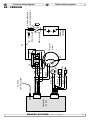
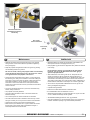
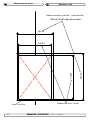
Thruster Systems EN Installation & User Guide NO Installasjons- og brukerveiledning SLEIPNER MOTOR AS P.O. Box 519 N-1612 Fredrikstad Norway Tel: +47 69 30 00 60 Fax: +47 69 30 00 70 w w w. s i d e - p o w e r. c o m s i d e p o w e r @ s l e i p n e r. n o Made in Norway SIDE-POWER SR(P) 80/185 T SR (P) 100/185 T © Sleipner Motor AS version 1.4 - May 2014 EN Contents Installation instructions Measurements, thruster..............................................................3 Technical specifications...............................................................4 Thruster installation Positioning of the thruster unit ....................................................5 Hatch cut out...............................................................................6 Fitting the hatch ......................................................................... 7 Moulding......................................................................................8 Fitting the electromotor ...............................................................9 Electrical installation..................................................................10 Technical wiring diagram - SR...................................................11 Technical wiring diagram - SRP.................................................12 Maintenance..............................................................................13 Measurements, hatch................................................................14 Template, holes in hatch............................................................15 S-link installation System overview.......................................................................16 Planning & precautions ............................................................17 System schematics - SR...........................................................18 System schematics - SRP.........................................................19 User’s manual General use & alarm indications - SR......................................20 General use & alarm indications - SRP....................................21 Installation checklist................................................................. 22 Important user precautions....................................................... 23 Troubleshooting........................................................................ 24 Warranty statement ............................................................... 26 Spareparts list & drawing ..................................................... 27 Service centres ...................................................................... 28 DECLARATION OF CONFORMITY We, Sleipner Motor AS P.O. Box 519 N-1612 Fredrikstad, Norway declare that this product with accompanying standard remote control systems complies with the essential health and safety requirements according to the Directive 89/336/EEC of 23 May 1989 amended by 92/31/EEC and 93/68/EEC. NO Innhold Installasjonsinstrukser Målskisse, truster........................................................................3 Tekniske spesifikasjoner..............................................................4 Trusterinstallasjon Plassering av enheten ................................................................5 Utskjæring av luke.......................................................................6 Tilpassing av luke ...................................................................... 7 Laminering...................................................................................8 Montering av elektromotor ..........................................................9 Elektrisk installasjon..................................................................10 Teknisk koblingsskjema - SR.....................................................11 Teknisk koblingsskjema - SR.....................................................12 Vedlikehold................................................................................13 Målskisse, luke..........................................................................14 Mal, hull i luke............................................................................15 S-link installasjon Systemoversikt..........................................................................16 Planlegging og forbehold ..........................................................17 Koblingsskjema - SR.................................................................18 Koblingsskjema - SP.................................................................19 Brukermanual Betjening og alarmindikering - SR............................................20 Betjening og alarmindikering - SRP..........................................21 Sjekkliste.................................................................................. 22 Viktige brukerforbehold............................................................. 23 Problemer og løsninger............................................................ 25 Warranty statement ............................................................... 26 Deleliste/tegning .................................................................... 27 Servicesentre ......................................................................... 28 Samsvars erklæring Sleipner Motor AS Postboks 519 N-1612 Fredrikstad, Norge Erklærer at dette produktet med tilhørende standard kontrollsystemer er i samsvar med helse, og sikkerhetskravene i henhold til Direktiv 89/336/EEC FRA 23 Mai 89, korrigert av 92/31/EEC og 93/68/EEC. EN Measurements, thruster Målskisse, truster NO SR(P)80/185T SR(P)100/185T SR(P)80/185T - SR (P) 100/185T version 1.4 - May 2014 3 WATERLINE Min. 185mm Technical specifications EN Motor: Custom made reversible DC-motor. Gearhouse: Seawater resistant bronze. Ballbearing at propellershaft and combination of ballbearing and slide bearing at driveshaft. Motor bracket: Seawater resistant aluminium, galvanicly insulated from motor Tunnel: Tekniske spesifikasjoner NO Motor: Spesialutviklet reversibel DC-motor. Girhus: Sjøvannsbestandig bronsje. Kulelagre på propellaksel. Kule og glidelager komb. på drivaksel. Motorbraket: Sjøvannsbestandig aluminium. Galvanisk isolert fra motor Cross spun with rowing G.R.P tunnel Tunnel: Kryssvevet glassfiber. Propeller: 5 blade skew "Q"-propeller, fibreglass reinforced composite. Propell: 5-blads skew "Q"-propell i komposittmateriale. Batterier: Batteries: Minimum recommended battery capacity (cold crank capacity by DIN/SAE standard) SR 80/185T 12V : 550 CCA DIN/1045 CCA SAE SR 80/185T 24V : 300 CCA DIN/570 CCA SAE SR 100/185T 12V : 750 CCA DIN/1425 CCA SAE SR 100/185T 24V : 400 CCA DIN/760 CCA SAE Minimum anbefalt batteri størrelse. (Kaldstart kapasitet etter DIN/SAE std.) SR 80/185T 12V : 550 CCA DIN/1045 CCA SAE SR 80/185T 24V : 300 CCA DIN/570 CCA SAE SR 100/185T 12V : 750 CCA DIN/1425 CCA SAE SR 100/185T 24V : 400 CCA DIN/760 CCA SAE Max. use: SR: S2 = 3 min. or appr. 7-10% within a limited time frame. Drift tid: SR: S2 = 3 min. eller gjennomsnittlig 7-10% innen en begrenset tidsperiode. load. Remaining run time shown on control panel. SRP: Opp til kontinuerlig driftstid alt etter belastning. Status for kjøretid vises i display Sikkerhet: Safety: Electronic time-delay device protects against sudden change of drive direction. Electric thermal cut-off switch in electromotor protects against over heating (auto reset when electro motor cools down). Elektronisk tidsforsinkelse forhindrer motorskade ved rask retningsendring. Motoren stanser automatisk ved overopphetning (slår seg automatisk på etter nedkjøling). Flexible coupling between electro-motor and driveshaft protects electromotor and gearsystem if propeller gets jammed. Fleksibel kobling mellom drivaksel og motor beskytter gir hvis propell blir blokkert. S-Link panelet slår av trusteren og feller den inn 6 minutter etter siste gangs bruk S-link panel shuts off automatically and retracts thruster 6 minutes after last use. Integrated microprocessor monitors solenoids, reducing wear and risk of solenoid lock-in. Auto-stop of thruster in case of accidental solenoid lock-in or if run signal is continous for more than 3 minutes Integrert microprossessor føler hele tiden på releet, reduserer slitasje og risk for ”heng” på relé. Trusteren vil stoppe automatisk etter 3 minutter om det oppstår ”heng” på relé, eller om trøsteren går kontinuerlig i 3 minutter. SRP: Up to continuous run time depending on 4 SR(P)80/185T - SR (P) 100/185T version 1.4 - May 2014 CENTERLINE, THRUSTER FORWARD PLACEMENT MARKING B A CENTERLINE, HULL FRONT FRONT Reference height, front and aft Mark cut line A Transfer hull shape EN A A FRONT FRONT Positioning the thruster NO Plassering av enheten 1. Find the most forward position where thruster unit will fit, and the top of the deployed thruster tunnel is at min. 185mm. Remove countermould on inside of hull, with min. 20 cm clearence to all sides of the thruster unit to give room for moulding. 1. Finn den fremste posisjonen hvor enheten får plass, og slik at toppen på den utfelte thrustertunnellen havner minst 185mm under vannlinjen. Fjern så evt. innerskrog med minst 10 cm klaring rundt hele enheten for å få plass til innstøping. Place unit where intended, take necessary measurements to check that a complete unit with motor, relay cover and actuator cover fits in the designated space. Plasser enheten der du mener den skal stå, mål og se til at det er plass til en komplett enhet der med motor, relé deksel og deksel over aktuator. 2. Find centerline of boat and centerline of thuster unit and mark accordingly. 2. Finn senter i båten og merk dette samt senter på enheten og merk også dette i begge ender av enheten. Mark guideline/points for longitudinal orientation of thruster unit. Merk også på en hjelpelinje/punkt for senere orientering av enheten i lengderetning. 3. Measure distance from hull to lower part of the straight longitudinal of thruster unit, please observe that distance can vary between the front and aft end wall. Use measurement from back part to draw rear cut line, and front measurement to draw front cut line. The straight longitudinal edges of unit must not be cut (reference point for hull mounting) 4. Position unit to center marks and longitudinal guidelines/marks. 3. Mål fra skroget og opp til nedre del av den rette langsgående kanten på enheten, merk at det kan være forskjellig mål foran og bak. Bruk målet bak for merking av kutt linje bak, respektivt målet foran for kutt linje foran. Bruk målet og trekk en linje langs bakre respektive foran på enheten. Det skal ikke kuttes noe på de langsgående kantene på enhetens kasse, de er på riktig avstand og skal være referanse for montering på skroget. 4. Plasser enhet tilbake på sentermerker, og mot hjelpelinjen/punktet i lengderetningen. SR(P)80/185T - SR (P) 100/185T version 1.4 - May 2014 5 m m 12 OUTLINE, THRUSTER CASING MARK OUTLINE OF THRUSTER CASING Template, hatch 115mm m 115mm 5m Drill holes 32 115mm ? 115mm Drill holes Cutting out the hatch EN Draw outline of complete unit circumference with marker before removing unit 5. Draw a line 12 mm in front of the rear end of unit outline, this marks the aft cut line for the hull. Draw outline of hatch according to measurement drawing on page 12 ( hatch sides 115mm each side of centerline, front cut line 325mm from aft cut line). Align hatch drilling template (page 13) with centerline and aft cutline and mark and drill the four holes used to secure hatch to mechanism. 6. Use appropriate tool and cut out the hatch with a 45 degree chamfer outwards from centre of hatch. NOTE: Secure hatch with duct tape or similar before completing all cuts, to prevent that the hatch drops and get damaged When done cutting, you have the hatch to be fitted to the retract mechanism. Fill edges of hatch and hull with epoxy/cutting to compensate for thickness of cut. 6 NO Utskjæring av luke Marker omrisset av enheten før du tar den ut igjen. 5. Trekk en linje 12mm foran den bakre kanten av omrisset og du har den bakre kuttlinjen for luken. Tegn opp omrisset av luken i henhold til måltegning, luke på side 12 (sidekanter 115mm til hver side av senterlinjen, fremre kutt linje 325mm fremover fra bakre kuttlinje). Bruk bakre kuttlinje og senterlinje i båten som utgangspunkt for lukemalen (side 13) og projiser og bor de fire hullene for å feste skrogdelen til thrusteren 6. Luken kuttes ut med 45 graders vinkel utover, slik at åpningen blir størst på utsiden av skroget. Luken må kuttes ut nøye, med dertil egnet verktøy OBS. Før alle kutt er utført anbefales det å tape fast luken slik at den ikke faller ut når kuttene er utført. Når du har kuttet ferdig skal du ha en pen luke med et tilhørende pent hull. Forsegl kantene på luke og skrog med epoxy og glassfibercutting for å fylle igjen tykkelsen etter kuttet. SR(P)80/185T - SR (P) 100/185T version 1.4 - May 2014 Loosen actuator from front mounting point Hull Thruster casing Cut, 45 degree chamfer outwards Wedges/shims in all four corners EN Fitting the hatch NO Tilpassing av luke 7. Place unit according to marks and check that hull opening is correctly placed and is of correct size. 7. Sett deretter enheten på plass over hullet, og kontroller at hullet er korrekt og i riktig størrelse. Loosen actuator from front mounting point and carefully swing the retracting unit out of hull (people outside hull recommended to control moving part of thruster) Ta av aktuator i fremre innfesting og sving retracten forsiktig ut av skroget. Til denne jobben anbefales det at du har en hjelper på utsiden av skroget for å ta imot den utsvingbare delen på trusteren. Mount the hatch to the retract mechanism, fold mechanism back into hull, and remount actuator. Deretter skrus luken på plass på bunnrammen, og foldes inn og aktuator monteres på igjen. With hach and actuator mounted, use wedges/shims in each corner of thruster grp casing to make the hatch fit tight in the opening. The hatch should be parallel with the hull on all edges, and the gap between hatch and hull should be equal on all four sides. Det er en fordel å se til at luken har en jevn tykkelse over det hele før den skrus fast, dette for en penest og best mulig installasjon. When the casing is secured with the hatch in the correct place with wedges/shims, mould in the casing. Sleipner Motor AS recomends to use resin and fiberglass cutting mixed to a paste to be used between casing and hull before moulding/ laminating the casing to the hull - to avoid resin to flow into the casing, and to avoid the risk of getting the hatch stuck to the opening. Når luke og aktuator er montert, shimses / kiles kassen i hvert hjørne innvendig opp slik at luken passer perfekt i hullet. Luken skal ligge parallelt med skroget rundt og glippen mellom luke og skrog skal være lik hele veien rundt. Når det er gjort, lamineres enheten fast. Sleipner Motor AS anbefaler å bruke f. eks. epoxy og glassfiberkutting blandet til en fast masse som legges mellom enheten og skrog før laminering. Dette for å unngå at det renner epoxy inn i enheten og limer igjen luke til skrog. SR(P)80/185T - SR (P) 100/185T version 1.4 - May 2014 7 Profile, moulding 1 Profile, moulding 2 Profile, moulding 3 EN Moulding Begin grinding from inside of line drawn around thuster unit inside hull, starting with a depth of 2/3 hull thickness moving outwards with decreasing depth. Grind thruster casing in similar manner, deepest on lower edge, decreasing upwards. Grind with power tool or by hand on inside of casing and inside of marking line on hull to accommodate 2-3 layers of WR 9. After grinding and cleaning, place unit in final location and prepare for moulding. Mould the unit thoroughly to the inside of hull and from outside into casing Ref illustration ”Profile, molding 1-3”. 8. The unit is now almost ready to be moulded to the hull (Epoxy and WR - woven rowing - recommended) Before starting to grind the hull and thuster casing, please cover thuster unit and inside of boat carefully. (Note, if the hull has a sandwich construction, all core material must be removed, and be rebuilt with WR by qualified personel) NO Laminering 8. Nå er enheten klar for laminering (Sleipner Motor AS anbefaler epoxy og WR(vevd matte) glassfiber matte). Før du starter med å slipe i skrog og glassfiberkassen på enheten må du være nøye med og maskere alt i båten og på enheten. (NB; Er skroget av sandwich type, må alt av kjernemateriale fjernes helt ut til det ytre skinnet av skrog, for så å bygges opp igjen med WR glassfiber matte) Slipingen starter på innsiden av som rundt enheten streken ble trukket av skroget, og igjennom 2/3 av på innsiden skroget og mindre og mindre lengre ut til du er i null. Det samme gjøres på glassfiber kassen på enheten, slip mest på nedre kant og mindre oppover kasse. Slip også med verktøy eller for hånd på innsiden av glassfiber kassen på enheten og på innsiden av streken på skrog, dette for og få heft til to-tre lag med glassfiber matte her også. 9. Etter sliping og grundig rengjøring plasseres enheten på plass, og du er nå klar for laminering. Enheten lamineres fast grundig på innsiden av skroget, og på utsiden av skroget og inn i kassen. Se illustrasjon ”Profil laminering 1-3”. 8 SR(P)80/185T - SR (P) 100/185T version 1.4 - May 2014 Bolt tightening force (4x): SR80/100: 33 Nm (24 lb/ft) Adjustment screws for end-stop microswitch EN Fitting the electromotor NO End-stop sensor Montering av elektromotor 1.Remove the 4 bolts in the motor bracket. 2.Place the motor gently on the motor bracket. Be careful, the motor is heavy! Ensure that key on axle and keyway in one-piece coupling are aligned. Ensure that you are placing the motor so that the cable terminals on it are available for electric installation later. 3.Fasten the motor to the bracket with the 4 bolts and tighten them. 4.Check if the springs for the brushes sit correctly on the brushes (see through the metal web around the top of the electromotor). 5.Check the drive system by turning the propeller, it will be a little hard to turn (because of the gear reduction and the motor), but you should easily be able to turn it by hand. 6. Remove solenoid cover and plug the cable from the actuators and sensors to the unoccupied plug in the controlbox located underneath the solenoids. Put cover back in place. 1. Fjern de 4 boltene i motorbraketten. 2. Plasser motoren på braketten. Plasser motoren slik at releene er tilgjengelige for tilkobling senere. Ta hensyn til at motoren er tung når den bæres og håndteres. Sjekk at kilespor i gummikobling og kile på aksel er på linje. 3. Fest motoren til braketten med de fire boltene. 4. Sjekk at børstefjærene sitter korrekt på børstene (gjøres ved å se gjennom gitteret på siden av motoren). 5. Test installasjonen ved å dreie på propellen. Det vil være motstand pga. girutveksling og motor, men det skal enkelt la seg gjøre å dreie propellen for hånd. 6. Ta av reledekslet og plugg in ledningen fra aktuator og sensorer til den ledige kontakten på kontrollboksen under hovedreleene. Sett dekslet tilbake på plass. End-stop Micro-Switch adjustment 1.Remove actuator mechanism cover 2.Close retract mechanism manually, and hold it in the closed position 3.Losen the screws on the end stop microswitch 4.Adjust microswitch so that it engages and fasten screws, to ensure that the correct retract end position is defined NB! Paint the gearhouse and propeller with antifouling for propellers to prevent growth of barnacles or similar which would reduce the performance dramatically. Do not paint the propeller shaft, the zincanodes or the end face of the gearhouse. Justering av mikrobryter for endestopp 1. Ta av dekslet over aktuatormekanismen 2. Steng retract-mekanismen manuelt og hold den i lukket posisjon 3. Løsne skruene på mikrobryteren for endestopp 4.Juster mikrobryteren slik at den akkurat utløses og fest skruene for å definere den korrekte stillingen for en innfelt thruster NB! Do not run the thruster for more than very short bursts without being in the water. NB! If the boat is still being built when the electromotor is installed, it must be covered up to avoid dust from the building going into the motor and the solenoids. This cover must be removed before the thruster is being used. NB ! Påfør bunnstoff på girhus og propell for å unngå vekst som kan virke sterkt hemmende på thrusterens effekt. Sinkanoder propellaksling og tetninger skal ikke stoffes. NB ! Thrusteren må kun kjøres i meget korte perioder når den ligger på land. NB ! Hvis båten fortsatt er under bygging når thrusteren blir montert må motoren dekkes til for å unngå at støv og lignende trenger inn i girhus og elektromotor. Dekket må fjernes før motoren tas i bruk. SR(P)80/185T - SR (P) 100/185T version 1.4 - May 2014 9 Fig. 1 B C Fig. 2 A C SR - VERSION D E B A SRP - VERSION Battery & cable recommendations: Model SR80/185T SR100/185T Voltage Nominal Min. battery current CCA draw >7m total + & - 7-14m total + & - 15-21m total + & - 22-28m total + & - 28-35m total + & - 36-45m total + & - Min. Rec. Min. Rec. Min. Rec. Min. Rec. Min. Rec. Min. Rec. mm2 12 V 530 A DIN: 550 SAE:1045 AWG 60 2/0 70 2/0 95 3/0 2x 70 2x 2/0 2x 70 2x 2/0 2x 95 2x 2/0 2x 95 2x 3/0 270* 2x 120 2x 4/0 340* NA NA 24 V 260 A DIN: 300 SAE: 570 mm2 AWG 25 1 35 1 35 1 50 1/0 60 2/0 70 2/0 70 2/0 95 3/0 95 3/0 120 4/0 120 4/0 2x 95 2x 3/0 12 V 740 A DIN: 750 SAE: 1425 mm2 AWG 95 3/0 95 3/0 2x 70 2x 2/0 2x 95 2x 3/0 2x 95 2x 3/0 280* 250* 375* NA NA NA NA 24 V 340 A DIN: 400 mm 35 50 50 70 60 95 95 120 120 2x 95 2x95 2x 120 SAE: 760 AWG 1 1/0 1/0 2/0 2/0 3/0 3/0 4/0 4/0 2x 3/0 2x 3/0 2x 4/0 Minimum and recommended cable dimensions can be identical due to safety margins and cable heat considerations for short cable lenghts. Electrical installation EN NO Elektrisk installasjon • Explanation of electrical table • Forklaring til elektrisk tabell - All cable lengths are the total of A+B+C(+D+E) in Fig. 1. - Kabellengder tilsvarer totallengden A+B+C(+D+E), Fig. 1. - Battery size is stated as minimum cold crank capacity, not Ah. - Min. batterikap. som kaldstartkapasitet (CCA) i Ampere, ikke Ampere - Use slow fuse rated to hold stated Amp-Draw for min. 5 minutes. timer (Ah). • It is important that you use a good cable size and batteries with a 2 * Minimum or recommended cable cross section in mm2 high cranking capacity to feed the thruster, because it is the actual voltage at the motor while running the thruster that decides the output rpm of the motor and thereby the actual thrust. Please see the list below for advised min. sizes of cables and batteries. You can of course use larger cables for even better results. • A main switch that can take the load without noticeable voltage drop must be installed in the main positive lead so the power for the thruster can be turned off independent of the rest when not on board or in emergencies. This should be placed in an easy accessible place and the boats instructions should inform that this should be turned off like the boat’s other main switches. • We also advice to install a fuse in the positive lead for protection against short circuiting of the main cables. This fuse should be of a adequate quality which normally means that it is physically large as these have less voltage drop than the simple / small ones. It should be of the slow type and sized to take the amperage draw for at least 5 minutes. • It is highly recommended to install a Sidepower Automatic Main Switch 897712 (12V) eller 897724 (24V). The AMS will be activated when the panel is turned on, contains an automatic short circuit fuse and a manual emergency stop. The AMS will also provide feedback to the panel regarding evt. faults. • The cable ends must be fitted with terminals and these must be well isolated against contact with anything but the proper connection point. • Terminals must be properly tightened. Secure/hold inner nut when tightening (Fig. 2). Tighten ø10mm / 3/8" bolt with 15 Nm/11lb/ft. 10 - Bruk trege sikringer for å forebygge spenningsfall. • Det er viktig å bruke kabler som er store nok, og et batteri med god kaldstartkapasitet for å drive thrusteren. Det er spenninngen ( i volt) som kommer frem til motoren under kjøring som bestemmer turtallet til motoren og dermed også skyvekraften. Vær vennlig og jamfør listen over for minimum anbefalte kabel, og batteristørrelse. • En hovedstrømbryter som ikke medfører stor spenningsfall må installeres på thrusterens plusskabel. Det bør være mulig å skru av strømmen til thruster uavhengig av resten av det elektriske systemet, når man ikke er om bord, eller i et nødstilfelle. Bryteren bør plasseres på et tilgjengelig sted, og båtens instruksmanual må ta for seg at denne skal skrus av slik som de andre hovedbrytere. • Det må installeres sikring på pluss strømkabelen for å beskytte mot kortslutning av hovedstrømkablene. Sikringen bør være av høy kvalitet, noe som vanligvis betyr at de er fysisk store, for å unngå spenningsfall som ofte er resultatet av å bruke mindre, enklere sikringer. Sikringen skal være en treg type som tåler amper trekket til elektromotoren i minimum 5 min. • Det anbefales å bruke Sidepower automatisk hovedstrømbryter 897712 (12V) eller 897724 (24V).Denne aktiveres når panel slås på, og har også innebygget kortslutningsikring, samt en manuell nødstopp.Den gir også melding til panel ved evt. feil. • Kabelendene kan må påmonteres terminaler og disse må isoleres mot alt som ikke er riktig kontaktpunkt. • Det er viktig att kabelsko trekkes korrekt fast på koblingsbolt. Kontra mutter på koblingsbolt må holdes fast ved tiltrekking (Fig. 2). ø10mm / 3/8’’på motoren dras til med 15 Nm. SR(P)80/185T - SR (P) 100/185T version 1.4 - May 2014 Technical wiring diagram NO SR(P)80/185T - SR (P) 100/185T EN Teknisk koblingsskjema SR - VERSION version 1.4 - May 2014 11 12 SR(P)80/185T - SR (P) 100/185T Technical wiring diagram SRP - VERSION EN NO Teknisk koblingsskjema version 1.4 - May 2014 Check and relubricate with waterproof grease if neccessary Zinc anode, retract mechanism Zinc anode, gearleg EN Maintenance » Retighten the bolts holding the gearhouse to the motor bracket during the first on-land service with the specified bolt tightening force (see page 9). » Keep the propeller and gearhouse clean from growth by painting with antifouling before every season. PS! The zinc anode, sealing and propeller shafts must absolutely not be painted. Be careful that you don’t fill paint in the “tracks” in the gearhouse that the propeller hub moves in. » Change the zinc anode before every season, or when about half the anode is gone. Always use a sealant on the screw holding the zincanode to ensure that it does not fall off. Please observe that in some waterconditions it can be necessary to install an extra zincanode to ensure that it lasts for the whole period between regular service lifts of the boat. Consult your dealer for information on how to do this. » As a part of the seasonal service of your boat, and before every season, always check that: NO Vedlikehold » Etterstram boltene som holder girhuset sammen med braketten ved første på-land servicen med oppgitt moment (s. 9). » Hold propellen og girhuset fritt for algevekst ved å påføre bunnstoff før hver sesong. PS ! Sinkanoder, tetninger og propellaksel skal ikke påføres bunnstoff, pass på så det ikke kommer bunnstoff i gjengesporene til propellmutteren. » Skift sinkanode før hver sesong, eller når ca. halvparten av sinkanoden har tæret bort. Bruk Locktite eller lignende på skruen til sinkanoden for at den ikke skal falle av. Ta i betraktning at under noen vannforhold er det nødvendig å montere en ekstra sink-anode for å være sikker på at de skal vare i hele perioden mellom vedlikehold. Ta kontakt med din forhandler for informasjon om hvordan å gjøre dette. » Som en del av det periodiske vedlikeholdet av din båt, og før hver sesong må følgende ting sjekkes: • Propellen sitter godt festet. • Boltene som holder elektromotoren til braketten sitter. • The propeller is securely fastened • At universalleddet i retract-mekansimen er smurt • The bolts holding the electric motor to the motor bracket are fastened correctly. • Skottet der baugpropellen er montert skal være rent, og tørt. Hvis det er vann i skottet må lekkasjen finnes og tettes. • The universal joint in the retract mechanism is lubricated • Alle elektriske tilkoblingspunkter er rene, og godt festet. • The area where the thruster is installed is clean and dry. If there are signs of water you must try to find the source and eliminate it. • All electrical connections are clean and fastened firmly. • Pass på at batteriene er i god stand slik at de kan gi høy spenning til trusteren. Redusert spenning vil gi redusert effekt på trusteren. • Make sure that your batteries are in a good condition so that the thruster gets a good voltage. Old or bad batteries will give a reduced performance from the thruster. SR(P)80/185T - SR (P) 100/185T version 1.4 - May 2014 13 Measurements, hatch EN NO Målskisse, luke Measurements, outside - gelcoat side Measurements, inside Inner cut line 14 SR(P)80/185T - SR (P) 100/185T version 1.4 - May 2014 Template, holes in hatch EN Rett inn etter indre bakre kuttmarkering for luke Align with inner rear cut-out line, hatch Mal, hull i luke NO SR(P)80/185T - SR (P) 100/185T version 1.4 - May 2014 15 Example of wiring Wiring of S-link system Wiring of S-link system Explaining S-link S-link is aExplaining ”CanBus” basedS-link control system e Example Example S-linkfull is aintelligent ”CanBus”communication based control system with with full intelligent between all units incommunication the system, much like between all network. units in the system, much like a computer a computer network. Main advantages include: -MainRound, compactinclude: and waterproof plugs with advantages Bow Automatic tion 00% Power Control unique keying to and avoid faulty hookup - thruster Round, compact waterproof plugs with mainswitch supply panel number of commands or information unique keying to avoid faulty hookup Wiring- of Unlimited S-link system transfer onnumber a singleofcable Unlimited commands or information ing of S-link system Proprietary Sleipner commands, but built 100% NO Bow EN S-link system overview transfer on a single cable S-link systemoversikt Automatic thruster mainswitch on NMEA 2000 standard Sleipner but built S-link 100% Bow Automatic S-link cable parts er et ”CAN”-basert kontrollsystem med full intelligent kommunikasjon S-link is a- ”CAN”Proprietary based control system with full commands, intelligent communication Example of wiring mellom alle enheter i systemet, på samme måte som et datanettverk. between all unitson in the system, much like a computer network. thruster mainswitch NMEA 2000 standard Wiring of S-link system cable (spur) Example Power of wiring Main advantages include: Wiring of S-link Mustunique be one in each system, - Round, compact and waterproofsystem plugs with keying and color coding to avoid faulty hookup delivered in the length of 2,5m - Unlimited number of commands or information a single cable Part #:transfer 6 1328onwiring Backbone cables Example - Proprietary Sleipner commands, but built 100% onof NMEA 2000 standard Forms the main cables ”loop” around the boat Backbone Part #: 6Example 1320-xxM (xx=length) of wiring Forms the main ”loop” around the boat T-connector Blant hovedfordelene: - Runde, kompakte og vanntette plugger med unik “keying” og fargekoding for å unngå feilkoblinger - Ubegrenset antall kommandoer eller informasjonsfllyt i en enkel kabel - Proprietære Sleipner kommandoer, men 100% basert på NMEA 2000 standarden S-link cable parts S-link cable parts Power cable (spur Must be one in each(spur system Power cable delivered in the length of 2, 0,2 m BACKBONE cables Part #: 6 1320-xxMMust (xx=length) be one for each spur, m Forms the main “loop” around the2,0 boat. 0,2 m Part #: 6 1320-xxM (xx=length) 4,0 m including the power cable 2,0 m 6 1320-0,2M (0,2m) 7,0 m Part #: 6 1326 4,0 m 6 1320-2M (2,0m) 15,0 m 7,0 m 6 1320-4M (4,0m) 20,0 m (one for each component, no 15,0 m 6 1320-7M (7,0m) ossible 6 1320-15M (15,0m) 20,0 m Must be one in each end 6 1320-20M (20,0m) BACKBONE kablerMust be one in each system Part rundt #: 6 1328 Danner “hovedsløyfen” båten. delivered iin the length of 2, Art. nr: 6 1320-xxM (xx=lengde) Part #: 6 1328 6 1320-0,2M (0,2m) 6 1320-2M (2,0m) 6 1320-4M Must (4,0m)be one for each spur, 6 1320-7M (7,0m) including the power cable 6 1320-15MMust (15,0m) be one for each spur, #: 6 1326 6 1320-20MPart (20,0m) including the power cable T-connector T-connector End terminator SpurAutomatic cables of the backbone ”loop” Power Bow Control Part #: 6 1326 Must be used to connect all parts to the backbone cable (one for each component,SPUR no kabler SPUR cables Spur cables Part #: 6 1327 thruster mainswitch supply panel Must be used to connect all parts to the exeptions), recommended to be asPower short as practically possible Endalleterminator Må benyttes for å koble komponenAutomatic Control Must be used to connect all parts to the backbone cable (one for each component,tene no til backbone-kabelen ( en for hver backbone cable ( one compoPartfor#:each 6 1321-xxM (xx=length) Must be one in each end exeptions), recommended to be assupply short as practically possible End terminator r mainswitch panel nent, no exeptions), recommended be komponent, uten unntak), å ha 0,4to m of the anbefalt backbone ”loop” Partpossible. #: 6 1321-xxM (xx=length) as short as practically 1,0 m 0,4 m Bow Part #: 6 1321-xxM (xx=length) Automatic 3,0 m 6 1321-0,4M (0,4m) nk cable parts 1,0 m hruster 6 1321-1M (1,0m)mainswitch 5,0 3,0 m m Bow Automatic 6 1321-3M (3,0m) able parts Power cable 5,0 m (spur) thruster 6 1321-5M (5,0m) mainswitch Must be one in each system, Power supply Power supply Must be one in each end så korte lengder som mulig. #:backbone 6 1327 ”loop” Control Art. nr: 6 1321-xxMPart of(xx=length) the 6 1321-0,4M (0,4m) panel Part #: 6 1327 Control 6 1321-1M (1,0m) 6 1321-3M (3,0m) panel 6 1321-5M (5,0m) Power cable (spur) POWER cable delivered in the length of 2,5m Must be one in each system, 2.5m Part #:each 6length 1328 Must be one in system, Part #: 6 1328 nk cable parts delivered in the length of 2,5m nk cable Part parts #: 6Power 1328 cable (spur) POWER kabel Må være en i hvert system, lengde 2.5m Art. nr: 6 1328 T-connector Power cable (spur) T-connector Must be one in each system, Must be one forlength each spur, T-CONNECTOR delivered in the of 2,5m Must be one for each spur, including including the power Part #: 6 1328 Must be one in each cable system, power cable Part #: each 6 1326 Must be one for spur, delivered in the length of 2,5m Part #: 6 1326 including the power cable mponent, no T-CONNECTOR Må benyttes for hver spur-kabel, inkludert Power-kabel Art. nr: 6 1326 Part #: 6 1328 Part #: 6T-connector 1326 End terminator Must be one for each spur, Must be one eachcable end BACKBONE EXTENDER T-connector including the in power terminator of the backbone ”loop” ConnectsEnd two backbone cables to extend Part 1326 Must#: be6one for each spur, lenght Must be one in end Part #:each 6 the 1327 including power cable of the backbone mponent,Part no#: 6 1322 Part #: ”loop” 6 1326 Part #: 6End 1327 terminator mponent, noTERMINATORMust be one in each end END End terminator Must be one in each end the backbone of theofbackbone ”loop” “loop” Must#: be6one in each end Part 1327 Part #: 6 1327 of the backbone ”loop” Part #: 6 1327 no 16 SR(P)80/185T - SR (P) 100/185T BACKBONE EXTENDER Kobler sammen to backbone-kabler for å øke lengden Art. nr: 6 1322 END TERMINATOR Må benyttes i hver ende av backbone”hovedsløyfen” Art. nr: 6 1327 version 1.4 - May 2014 Example of the control wiring with S-link system for boats with one control position and one retractable thruster. You need: S1=_____ 2 x 6 1327 End terminators 3 x 6 1326 T-connectors 1 x 6 1328 Power spur 2 x 6 1320-xxM Backbone cables 2 x 6 1321-xxM Spur cables BB2=___ S2=_____ BB1=___ Positive, pos &Negative neg Shield +& ground EN S-link planning & precautions NO S-link planlegging og forbehold Routing the Backbone: Plan routing of the backbone so that lenght of spur cables will be kept at a minimum. Ruting av Backbone: Planlegg leggingen av “backbone”-kabelen slik at lengdene på “spur”-kablene blir kortest mulig. Avoid routing the S-link cables close to equipment that might cause interference to the S-link signals, such as radio transmitter equipment, antennas, high voltage cables etc. Unngå å legge S-link kabelene i nærheten av ledninger eller utstyr som kan skape forstyrrelser for S-link signalene, slik som radiosendere, antenner, høyspentkabler etc. The backbone MUST be terminated in each end with the 6 1327 End Terminator. “Backbone”-kabelen MÅ termineres i begge ender med 6 1327 “Terminatorplugg” Spur cables: Spur cables can be left unterminated (i.e. routing can be prepared for future additional equipment), make sure to protect open connectors from water and moisture to avoid corrosion in connector . Spur kabler: “Spur”-kabler kan kobles til “backbone”-kabelen uten å termineres (f.eks for klargjøring av fremtidig tilleggsutstyr), sørg for for å beskytte de åpne kontaktene fra fukt for å forhindre korrosjon i kontakten. SR(P)80/185T - SR (P) 100/185T version 1.4 - May 2014 17 S-link system schematics EN SR - VERSION NO S-link koblingsskjema The S-link control system is powered by a dedicated power cable connected to the system backbone as a normal spur cable. S-link systemeter strømforsynt via en dediker strømkabel som kobles til systemets “backbone” som en normal “spur”-kabel. The cable ends connect to battery pos. and battery neg. and the cable shield connects to battery neg. Kabelendene kobles til batteriets pluss- og minuspol og skjermkabelen kobles til batteriets minuspol. The battery pos. must be connected through a 5A fuse. Ledningen som kobles til batteriets plusspol må sikres med en 5A sikring 18 SR(P)80/185T - SR (P) 100/185T version 1.4 - May 2014 NO S-link system schematics EN SRP - VERSION S-link koblingsskjema The S-link control system is powered by a dedicated power cable connected to the system backbone as a normal spur cable. S-link systemeter strømforsynt via en dediker strømkabel som kobles til systemets “backbone” som en normal “spur”-kabel. The cable ends connect to battery pos. and battery neg. and the cable shield connects to battery neg. Kabelendene kobles til batteriets pluss- og minuspol og skjermkabelen kobles til batteriets minuspol. The battery pos. must be connected through a 5A fuse. Ledningen som kobles til batteriets plusspol må sikres med en 5A sikring SR(P)80/185T - SR (P) 100/185T version 1.4 - May 2014 19 Green status LED Green status LED RED status LED RED status LED YELLOW status/on-off LED YELLOW status/on-off LED EN General use & alarm indication - SR NO Betjening og alarmindikering - SR PANEL push both “ON” buttons simultaneously, thruster deploys. GB ON: General use & alarm indication PANEL OFF: push “OFF” button, thruster retracts. PANEL ON: push both “ON” buttons simultaneously, thruster deploys. OperateOFF: thruster by“OFF” pushing red and greenretracts. arrows. PANEL push button, thruster PANEL PÅ: Trykk begge “ON”-knappene samtidlig og trusteren felles ut N Betjening og alarmindikering PANEL AV: Trykk på “OFF”-knappen og trusteren felles inn. PANEL PÅ: Trykk begge “ON”-knappene samtidlig og trusteren felles ut Betjen trusteren av den rødeogogtrusteren grønne pilknappen. PANEL AV: Trykkved på hjelp “OFF”-knappen felles inn. STATUS/ALARM LEDS: Operate thruster by pushing red and green arrows. GREEN LED flashes during deploy phase, Solid GREEN LED indicates thruster deployed LEDS: and ready to operate. STATUS/ALARM RED LED flashes during retract phase, all LEDs whenLED panel/thruster GREEN LED ashes during deploy phase, Solid out GREEN indicates is shut down. thruster deployed and ready to operate. If something unexpected happens whileall deploying/retracting thruster, RED LED ashes during retract phase, LEDs out when panel/thruster theshut LEDs will show alarm codes according to form below: is down. If something unexpected happens while deploying/retracting thruster, the LEDs will show alarm codes according to form below: STATUS OG ALARM LED: Betjen trusteren ved hjelp av den røde og grønne pilknappen. GRØNN LED blinker mens trusteren felles ut, fast lysende GRØNN LED forteller atOG trusteren erLED: ute og klar til bruk. STATUS ALARM RØD LED blinker under innfelling av felles trusteren, allelysende LED-er GRØNN slukkes når GRØNN LED blinker mens trusteren ut, fast LED trusterenatertrusteren inne og er systemet er slått av. forteller ute og klar til bruk. Hvis noe inntreffer mensavtrusteren felles eller inn, vil når RØD LEDuforutsett blinker under innfelling trusteren, alle ut LED-er slukkes LED-ene er vise alarmkoder i henhold tabellen under: trusteren inne og systemet er slåtttilav. Hvis noe uforutsett inntreffer mens trusteren felles ut eller inn, vil LED-ene vise alarmkoder i henhold til tabellen under: LED LED 1�zz 1�zz 2�zz 2�zz 2�zz 2�zz 3�zz 3�zz 3�zz 3�zz Panel alarmalarm indication Panel indication Failure Failure 1 flash YELLOW & GREEN - Pause Thruster, overtemp Retracts 2 flashes YELLOW & GREEN - Pause Thruster, low power Retracts 2 flashes YELLOW & RED - Pause Thruster IPC error Retracts 3 flashes YELLOW & GREEN - Pause Deploy operation obstructed Retracts 3 flashes YELLOW & RED - Pause Retract operation obstructed Aborts retract, deploys and retries to retract 3 times. If operation still is obstructed, retract stops on obstruction 1 flash YELLOW & GREEN - Pause Thruster, overtemp 2 flashes YELLOW & GREEN - Pause Thruster, low power 2 flashes YELLOW & RED - Pause Thruster IPC error 3 flashes YELLOW & GREEN - Pause Deploy operation obstructed 3 flashes YELLOW & RED - Pause Retract operation obstructed 1�zz 1 flash YELLOW & RED - Pause 1�zzz 1 flashes GREEN & RED - Pause Automatic Main Switch Power Actuator failure 1 flashYELLOW, YELLOW & RED - Pause Power failure, 1�zz Power failure, Actuator 3�zzz 3 flashes YELLOW, GREEN & RED - Pause Automatic Main Switch manual override LED 4�zzz 1�zz 2�zz LED 2�zz Panel, alarmindikasjon 4 flashes YELLOW, GREEN & RED - Pause 1 blink GUL & GRØNN - Pause 1�zz 1 blink GUL & GRØNN - Pause Feil Panel has no contact with thruster. Truster, overtemperatur 3 blink & GRØNN 2 blink GULGUL & GRØNN - Pause 2�zz 2 blink GUL & RØD - Pause Thruster IPC feil 3�zz 3 blink GUL & GRØNN - Pause Utfelling av truster hindres 3�zz 3 blink GUL & RØD - Pause Innfelling av truster hindres 1�zz 3 blink GUL & RØD - Pause Thruster, liteUtfellingav strøm Turn off panel, charge batteries. Turn off panel - thruster must be serviced by authorized personel.Turn off panel - thruster must be serviced Retracts authorized personel. by Turn off panel. Go for lower speed/deeper water. Retry. Retracts System shuts down None None None None Turn off panel. Go for lower speed/deeper Press both ON-buttons water. Retry.to deploy thruster. Turn Main-Switch off. Remove obstruction. truster hindres Strømfeil, Aktuator Felles inn Felles inn connections . Retry. Replace fuse onoff Automatic Switch Turn panel.Main Check main switch, fuse, cable connections, cables. Retry. Brukerhandling Turn off panel. Check main switch, fuse, cable connections, Slå av panel, vent 20 minutter. cables. Retry. Slå av panel, lad batteriene. Felles Thrusterreaksjon inn Felles inn Check power Automatic Switch Turntooff panel.Main Check actuator Pull up Automatic Main Switch Trusterreaksjon Felles inn feil Innfelling av thruster hindres 1 v GUL & RØD - Pause Turn off panel, wait for 20 mins. Turn off panel, charge batteries. Retracts None Truster, lite strøm Truster IPC Feil Thruster, overtemperatur 2�zz 3�zz 3�zz - Pause User action User action Turn off panel, wait for 20 mins. Press both ON-buttons to deploy thruster. Aborts retract, deploys and retries to retract 3 times. If operation still is Turn main switch off. Remove obstruction. Turn off panel. Check actuator connections . Retry. obstructed, retract stops on obstruction Pause 2 blink Panel GUL alarmindikasjon & RØD - Pause reaction System shuts down YELLOW, GREENGREEN & RED - Pause Main fuse blown 2�zzz 4 flashes YELLOW, & REDAutomatic No Switch contact with thruster 4�zzz 2 flashes 2 blink GUL & GRØNN - Pause Thruster reaction Thruster Retracts Felles inn Slå av panel - trusteren Brukerhandling kvalifisert Slå av panel, vent 20 personell. minutter. må repareres av Slå av panel. Kjør saktere Slå av panel, lad opp batteriene. eller på større dybde. Prøvmå igjen . Slå av panel, trusteren repareres av kvalifisert personell. Felles inn Avbryter innfelling, felles ut og prøver å Trykk begge ON-knappene for å felle trusteren kjør saktere eller på større dybde. Prøv igjen. felle inn 3 ganger. Hvis innfellingen Slå av panel, ut. Skru av hovedstrømsbryter. Fjern det som fremdeles er hindret, stopper bevegelsen hindrer bevegelsen. Trykk begge ON-knappene for å felle ut thruster. Skru av Avbryter innfelling, felles ut og prøver å felle inn 3 ved hindringen Felles inn ganger. Hvis infellingen fremdeles er hindret, stopper slår seg av bevegelsen Systemet ved hindringen hovedstrømsbryter. Fjern det som hindrer trusterens bevegelse. Slå av panel. Sjekk elektriske koblinger til 1 blink GUL & RØD - Pause Strømfeil, aktuator System shuts down aktuator. Prøv igjen. Slå av panel. Sjekk elektriske koblinger til aktuator. Prøv igjen. 1�zzz 1 blink GUL, GRØNN & RØD - Pause Feil på automatisk hovedstrømsbryter Ingen 2�zzz 2 blink GUL, GRØNN & RØD - Pause Sjekk elektriske koblinger til hovedstrømbryter. koblinger, kabler. Prøv igjen. Sikring røket, automatisk hovedstrømsbryter Ingen 1�zz 4�zzz 4 blink GUL, GRØNN & RØD - Pause Ingen kontakt med truster NB: THE3 MAIN SWITCH MUST BE TURNED OFF IMMEDIATELY blink GUL, GRØNN & RØD - Pause Automatisk hovedstrømsbryter slått av manuelt Ingen 3�zzz WHEN AN IPC-ERROR OCCURS, TO PREVENT OVERHEATING OF 4 blink GUL, GRØNN & RØD - Pause Ingen kontakt med truster Ingen 4�zzz THRUSTER THE MAIN RELAYS! NB: THE MAIN SWITCH MUST BE TURNED OFF IMMEDIATELY WHEN AN IPC-ERROR OCCURS, TO PREVENT OVERHEATING OF THRUSTER WILL NOT RETRACT WHILE REVERSING AT “HIGH” THE THRUSTER MAIN RELAYS! NB: THE MAINWILL SWITCH MUST THE BE TURNED IMMEDIATELY SPEED. THIS TRIGGER “Retract OFF operation obstructed” WHEN AN IPC-ERROR OCCURS, TO PREVENT OVERHEATING OF ALARM. THRUSTER WILLMAIN NOT RETRACT THE THRUSTER RELAYS! WHILE REVERSING AT “HIGH” SPEED. THIS WILL TRIGGER THE “Retract operation obstructed” IF ALARM IS TRIGGERED, REDUCE SPEED AND PRESS BOTH “ON” ALARM. THRUSTERBEFORE WILL NOT RETRACT WHILE REVERSING AT “HIGH” BUTTONS RETRYING “OFF” BUTTON SPEED. THIS WILL TRIGGER THE “Retract operation obstructed” IF ALARM IS TRIGGERED, REDUCE SPEED AND PRESS BOTH “ON” ALARM. BUTTONS BEFORE RETRYING “OFF” BUTTON Ingen Slå av panel. Sjekk hovedbryter, sikringer, el. Bytt sikring i hovedstrømsbryter. NB: VED IPC-FEIL MÅ HOVEDSTRØMSBRYTER SLÅS AV UMIDTrekk opp rød knapp på hovedstrømsbryter. DELBART FOR Å FORHINDRE VARMEUTVIKLING I TRUSTERENS Slå av panel. Sjekk hovedstrømsbryter, sikringer, kabler. Prøv HOVEDRELER ! NB: VED IPC-FEIL MÅ HOVEDSTRØMSBRYTER SLÅS AV UMIDigjen DELBART FOR Å FORHINDRE VARMEUTVIKLING I TRUSTERENS THRUSTER FELLES IKKE INN VED BAKKING I ”HØY” FART. HOVEDRELER ! MÅ HOVEDSTRØMSBRYTER SLÅS AV UMIDNB: VED IPC-FEIL DETTE VIL UTLØSE ALARM ”Innfelling av thruster hindres”. DELBART FOR Å FORHINDRE VARMEUTVIKLING I TRUSTERENS THRUSTER FELLES IKKE INN VED BAKKING I ”HØY” FART. HOVEDRELER ! HVIS ALARM UTLØSES, REDUSER FARTEN OG TRYKK BEGGE DETTE VIL UTLØSE ALARM ”Innfelling av thruster hindres”. ”ON” KNAPPENE FØRST FØR ”OFF” TRYKKES PÅ NYTT. THRUSTER FELLES IKKE INN VED BAKKING I ”HØY” FART. HVIS ALARM UTLØSES, REDUSER FARTEN OG TRYKK BEGGE DETTE VIL UTLØSE ALARM ”Innfelling av thruster hindres”. ”ON” KNAPPENE FØRST FØR ”OFF” TRYKKES PÅ NYTT. HVIS ALARM UTLØSES, REDUSER FARTEN OG TRYKK BEGGE ”ON” KNAPPENE FØRST FØR ”OFF” TRYKKES PÅ NYTT. IF ALARM IS TRIGGERED, REDUCE SPEED AND PRESS BOTH “ON” BUTTONS 20 BEFORE RETRYING “OFF” BUTTON SR(P)80/185T - SR (P) 100/185T version 1.4 - May 2014 SR80/185T - SR100/185T 1.1.0 - 2010 17 • Connectorforexternal“buzzer”/loudaudiblealarms Speedcontroljoystickfor bowthruster Holdingfunctionforautorunningofbowandstern thrusterstogetherinthe directionofthearrowsat selectedpower Press“+”formoreand “-”forlesspower. Speedcontroljoystickfor sternthruster Informationdisplay,see nextpagefordetails. Pressboth“ON”buttons simultanouslytoactivate controlpanel. Presstode-activate controlpanelorcancelor gobackinmenusystem MENU Presstochange Presstoaccessmenu betweendayand systemandchoose nightlight itemsinmenus SIDE-POWER THRUSTER SYSTEMS EN CONFIDENCE BY CONTROL General use & alarm indication - SRP NO User info, PJC-212 - 1/ Betjening og alarmindikering - SRP 1. Turn main power switch for the bowthruster on. (Always turn off the main power switch when not onboard.) A Side-Power Automatic Main Switch wil turn on/off when the panel is turned on/off 1. Skru på hovedstrømmen (skru alltid av hovedstrømmen når du ikke er om bord i båten). En Sidepower Automatic Main Switch slås på / av når panelet slå på / av. 2. Please take some time to exercise thruster usage in open water to avoid damages to your boat. 2. Det er fordel om baugtrusteren prøves på åpent vann den første gangen. 3. Turn the control panel on by pushing both “ON” buttons on the original Sidepower panel simultaneously. 3. Skru på kontrollpanelet ved å trykke inn begge ”on” knappene på Sidepower panelet. 4. Movethe joystick in the direction you wish the bow to move. Other controls like footswitches or toggle-switches on the throttle can be used. These connected to the S-link control system by a S-link interface (Refer to schematics in interface manual for in- stallation 4. Kjør baugen i samme ønsket retning som du beveger joysticken. Andre kontrollenheter som fotbrytere, eller brytere på gass hendel kan også brukes. Disse tilkobles S-link kontrollsystem via en spesiell interface-boks.(Se skjema i manual for interfaceboks). 5. Depending on the sideways speed of the bow, you must disengage the control device shortly before the bow is in the desired direction, as the boat will continue to move after stopping the bowthruster. How to use a single stern thruster Some boats might however have installed a single stern thruster because of space limitation in the bow. In this case the stern thruster is used in the same way as a single bow thruster or moving the boat’s stern. How to use a bow and stern thruster combined The combination of a bow and stern thruster offers total manoeuvrability to the boat and the opportunity to move the bow and the stern separately from each other. This enables you to move the boat sideways in both directions and to turn the boat around its own axis staying at the same place. Refer to the PCJ control panel manual for detailed instructions. 5. Avhengig av hvor stor fart baugen får sideveis må thrusteren stoppes før baugen er i riktig posisjon, dette fordi baugen vil fortsette sideveis litt etter thrusteren skrues av. Hvordan bruke en enkel hekkthruster Enkelte båter vil av plassmessige, eller andre hensyn bare installere en hekkthruster. I disse tilfeller brukes hekkthrusteren på samme måte som baugthrusteren. Hvordan bruke hekk og baugthruster kombinert Kombinasjonen av baug og hekkthruster gir en total kontroll over båtens bevegelser p.g.a. muligheten til å bevege hakken og baugen uavhengig av hverandre. Båten kan skyves sidelengs og dreies rundt sin egen akse. Se egen brukermanual for PJC betjeningspanel. • Det er også her en fordel å prøve ut systemet på åpent vann. • Again, if in doubt, try in open water first! SR(P)80/185T - SR (P) 100/185T version 1.4 - May 2014 21 EN Checklist Sjekkliste NO Propeller is fastened correctly to the shaft. Propellen er festet til akselen på korrekt vis. Propeller turns freely in tunnel. Propellen roterer fritt i tunnel. The zinc-anode holding screw is tightened well with thread glue. Festeskruen til sinkanoden er festet med gjengelim. Anti-fouling have been applied to the gearhouse and propeller but NOT on the zincanode or the gearhouse lid where the propeller is fastened. Bunnstoff er påført girhus og propell, men ikke på sinkanode, tetninger eller propellaksel. The brush springs are fitted correctly on the brushes in the electromotor (check through the grid around the top end of the motor). Correct drive direction as per controlpanel. All electrical connections are clean, dry and tight, and the correct cable, fuse and main switch sizes have been used. With a ohm meter check that there is no electrical connection between electromotor body and positive terminal on the motor and between the electromotor body and the negative (A1) terminal on the motor. Børstefjærene er riktig plassert mot børstene. Dette sjekkes ved å se gjennom gitteret på siden av motoren. Kontrollpanel gir korrekt kjøreretning på thrusteren. Alle elektriske koblinger er rene, tørre og tette. Korrekte kabler, sikringer og hovedstrømsbryter er brukt. Boltene som festet braket til girhus er festet korrekt. Boltene som festet motor til braket er festet korrekt. The bolts holding the gearhouse and motorbracket together are tightened correctly. The bolts holding the electromotor to its bracket are tightened correctly. The thruster has been installed as per the instructions in this manual and all points in checklist above have been controlled. Thrusteren er installert i henhold til instuksene gitt i denne manualen, og alle punkter i sjekklisten er kontrolert. Signed: ................................................ Date:............................... Signatur: ............................................... Extra pre-delivery tests by installer/yard who does not use other quality control systems ! Anbefalt før leverings test for installør / verft som ikke bruker andre kvalitetskontroll systemer! Thruster type: .................................................. Voltage: .................... Thrustertype: ................................................ Volt: ............................. Serial number: ................................. Date of delivery: ....................... Serienummer: ..................................................................................... Correct drive direction as per control panel: ..................................... Leveringsdato: .................................................................................... Voltage at thruster when running: ...................................................... Korrekt kjørerettning per kontrollpanel: .............................................. Battery cable size used: ..................................................................... Spenning målt på thruster under kjøring: ........................................... The compartment where the thruster is fitted is isolated from general bilge water and has no obvious or suspected risks for flooding. Strømkabler: ....................................................................................... Skottet hvor thrusteren er montert er isolert fra kjølvann og har ingen åpenbar risiko for lekkasje. Other comments by installer: 22 Kommentar fra installør: SR(P)80/185T - SR (P) 100/185T version 1.4 - May 2014 Dato: ................................ EN Important user precautions NO Viktige brukerforbehold • Ensure that you know the location of the main battery switch that disconnects the thruster from all power sources (batteries) so that the thruster can be turned off in case of a malfunction. • Forviss deg om at du kjenner plasseringen av hovedstrømsbryteren til baugtrusteren, som kutter all strøm til trusteren, så trusteren kan skrus av i nødstilfelle. • Always turn the main power switch off before touching any part of the thruster, as an incidental start while touching moving parts can cause serious injuries. • Før berøring av noen del av trusteren må alltid strømmen skrus av. En uønsket start kan volde stor fysisk skade. • Skru alltid av kontrollpanelet etter bruk. • Den maksimale sammenhengende kjøretiden for en elektrisk truster er ca. 3 min. - da vil en føler automatisk skru av motoren når den når en viss temperatur. Dette må tas i betraktning når en manøver planlegges. • Dette betyr at ved manøvere som tar lang tid vil ikke trusteren kunne brukes hele kontinuerlig. Ved manøvere som tar lang tid kan man bruke trusteren i ca 10 % av tiden, avhengig av temperaturen i vannet. • Bruk aldri trusteren når noen er i vannet, trusteren vil trekke gjenstander til seg og kontakt med propellen vil volde alvorlig skade. • Kjør aldri trusteren i mer enn 1 sek. når båten er på land. Uten motstand fra vannet vil thrusteren nå ødeleggende turtall svært fort. • Hvis thrusterne stopper å gi skyvekraft mens motoren er i gang, er det trolig oppstått problemer i girsystemet. Stopp umiddelbart å kjøre motoren, og skru den av. Uten motstand fra vannet vil thrusteren nå ødelegende turtall svært fort. • Når man forlater båten skal alltid hovedstrømsbryteren slås av. • Vi anbefaler å ha motoren i gang når trusteren kjøres. Da vil batterien vedlikeholdes, og det vil være høyere spenning til elektromotoren. Høyere spenning gir høyere turtall og bedre ytelse. • Ytelsen til en baugtruster avhenger av hvilken spenning motoren mottar under kjøring. Kapasiteten til batterier avtar etter hvert som de blir eldre, og dermed også ytelsen til trusteren. Ved å installere nye batterier vil trusteren yte maksimalt igjen. • Kun en kontroll skal brukes av gangen, hvis to kontroller brukes motsatt vei vil trusteren stoppe automatisk. Hvis to paneler opereres samme vei vil ikke dette skje. • Hvis trusteren ikke fungerer tilfredsstillende må feilen lokaliseres og rettes så snart som mulig, for at ikke trusteren skal ta ytterligere skade, skru av hovestrømsbryteren hvis feilen er av elektrisk art. • Always turn the control device off when the thruster is not in use. • The maximum continous usage time of the electrical thruster is approximately 3 minutes. The electromotor has a built in thermal cut-off switch that will shut off the electromotor if it is overheating and re-engage it when it has cooled down some. This should be considered when planning your maneuvering. • This also means that the thruster will limit its total running time per time period so that you can not count on the thruster to hold you in a current and side wind for extensive time periods. Depending on the surrounding temperatures etc. the thruster will be able to run approximately 10 % of the time. • Never use a thruster close to somebody in the water, as the thruster will draw objects close by into the tunnel and contact with the rotating propellers will cause serious injuries. • With the boat on land, only run the thruster for a fraction of a second, as without resistance it will accelerate very fast to a damaging rpm. Also, while the thruster is in air, make sure that the propellers have come to a complete stop before performing a directions change of the thruster, as it might cause damage to the thruster. • If the thruster stops giving thrust while the electromotor is running, chances are that there is a problem in the drive-system. You must then immediately stop trying to run it, and turn it off, as running the electromotor for more than a few seconds without resistance from the propeller, can cause serious damage to the electromotor. • When leaving the boat always turn off the main power switch for the thruster. • We advice to always keep the main engine(s) running while using a thruster. This will keep the batteries in a good charge condition. This will also give better performance to the thruster, as a higher voltage at the thruster results in a higher torque (power) in the electromotor. • Please note that the performance of a thruster strongly depends on the voltage available at the electromotor. This voltage will decrease by time because aging batteries have a reduction of capacity. By installing new batteries the effect of the thruster should be back at the original level. • Make sure that only one control is used at the same time, if two panels are operated in opposite directions at the same time the thruster will not run at all. If they are operated in the same direction the thruster will run in this direction. • If the thruster is not performing or functioning as usual, the cause for this must be found and corrected as soon as possible so to avoid causing any other or further damage to the equipment. You must also turn off the main battery switch immediately in case the problem is of electric origin. • Never store anything (e.g. equipment, sails, ropes etc.) in the same compartment as the thruster. When the thruster runs for a longer period it will get hot and will cause damage. SR(P)80/185T - SR (P) 100/185T version 1.4 - May 2014 23 Troubleshooting EN Before seeking assistance at the help desk of your Side-Power dealer/distributor please perform these tests and make notes of all measurements to ensure that they have as much information as possible to work on. Some error messages and alarms will be shown in the panel display. Please refer to the control panel manual. NB! All check points and solutions must be carried out after consulting the relevant information elsewhere in this manual to understand how the system is intended to work. If you are unable to understand what to check, you must consult a professional. Check Solution Not able to turn panel on with the ON-buttons Check S-link power supply No reaction when operating the panel A system scan must be executed. Refer to control panel manual » The thruster does not start at all or works only in one direction. The flexible coupling between motor and driveshaft or the propeller drive pin might have been damaged. The SR(P)80 og SR(P)100 models have a flexible coupling that can fail. The coupling is visible on the underside of the motor from inside the boat. Run motor and observe the coupling. Replace coupling if neccessary. If it is required to turn the drive shaft by hand, deploy the thruster as normal by turning the control panel on, wait until the thruster stops in deployed position and turn the battery switch off. Remove the fan cover on the motor to be able to turn it. Is the propeller properly attached to the propeller shaft and is the drive pin in place. Attach or replace propeller and/or drive pin Can the drive shaft be turned by hand with the electro motor removed. If the gear leg is damaged, it is recommended to replace the complete unit - not attempt to repair internal gears and bearings. » The thruster does not start at all or works only in one direction. Refer to the control panel manual for detailed explanations of warning and error codes shown on panel display/LEDs. » The thruster has an unexpected low performance. Check voltage at thruster battery when running. If less than 10,5 V / 21V the thruster will not perform at specified effect. Check that all the brush-springs sits correctly on the brushes in the electromotor. If one or more brushes are loose/has no tension from the brush-spring, the performance will be low. Check that the propeller, gearhouse and tunnel is free from growth/ barnacles etc. If there is growth in the tunnel, this will disturb/block the waterflow and especially barnacles on the propeller will greatly reduce performance. 24 SR(P)80/185T - SR (P) 100/185T version 1.4 - May 2014 Problemer og løsninger NO Før du søker hjelp hos din forhandler kan du foreta noen tester, og notere ned resultatet for at forhandleren skal ha mest mulig informasjon til rådighet. Noen feilmeldinger og alarmer vil kunne vises i betjeningspanelet. Vennligst se manualen for panelet. NB ! Alle sjekkpunktene på listen må sammenlignes med informasjon gitt tidligere i manualen for å forstå hvordan systemet skal fungere. Hvis du ikke forstår sjekklisten eller de relevante opplysningene gitt i manualen så må du ta kontakt med profesjonell hjelp. Kontroller Løsning Får ikke slått på panelet med ON-knappene Sjekk strømforsyningen for S-link Ingen reaksjon ved betjening av panel Det må kjøres en system scanning. Se manual for panelet. » Elektromotoren går, men det er ingen skyvekraft. Fleksibel kobling mellom motor og drivaksel, girhus eller drivpinne til propell kan ha blitt skadet Type SR(P)130 og SR(P)170 har fleksibel kobling som vil kunne slure når den er defekt. Koblingen er synlig på undersiden av motoren innvendig. Kjør motor og observer. Skift kobling om nødvendig. Dersom det er behov for å dreie på drivaksel for hånd kjøres denne ned på vanlig måte ved å slå på panelet, vente til den stopper i utfelt posisjon og deretter slå av batteribryteren. Skru av viftedekselet på motoren for å kunne dreie Er propellen festet til propellakselen, og er drivpinne på plass. Fest eller erstatt propellen og drivpinnen. Med elektromotoren avmontert, kan drivakselen vris for hånd for å sjekke om gir, og lager er i orden. I tilfelle girhuset er skadet anbefaler vi skifte girhus, fremfor å prøve å reparere innvendige gir og lagre. » Trusteren går bare i en retning, eller ikke i det hele tatt. Sjekk manualen for ditt panel for beskrivelser av feilmeldinger vist i panelets display/LED » Trusteren yter mindre enn ventet. Mål spenningen på thrusterbatteriet under kjøring. Er spenningen lavere en 10,5V / 21V vil trusteren sunke i turtall og skyvekraften senkes. Sjekk at alle børstefjærene ligger riktig an mot børstene. Trusteren vil ha lav skyvekraft hvis en eller flere børster ikke får trykk fra fjærene. Kontroller propell, girhus og tunnel, og fjern eventuell algevekst og lignende. Algevekst i tunnelen vil redusere vannstrømmen, algevekst på propellen kan redusere ytelsen betydelig. SR(P)80/185T - SR (P) 100/185T version 1.4 - May 2014 25 EN Warranty statement 1.The equipment manufactured by Sleipner Motor AS (The “Warrantor”) is warranted to be free from defects in workmanship and materials under normal use and service. 2.This Warranty is in effect for of two years from the date of purchase by the user. Proof of purchase must be included, to establish that it is inside the warranty period. 3.This Warranty is transferable and covers the product for the specified time period. 4.In case any part of the equipment proves to be defective, other than those parts excluded in paragraph 5 below, the owner should do the following: (a) Prepare a detailed written statement of the nature and circumstances of the defect, to the best of the Owner’s knowledge, including the date of purchase, the place of purchase, the name and address of the installer, and the Purchaser’s name, address and telephone number; (b) The Owner should return the defective part or unit along with the statement referenced in the preceding paragraph to the warrantor, Sleipner Motor AS or an authorized Service Centre, postage/shipping prepaid and at the expense of the Purchaser; (c) If upon the Warrantor’s or Authorized Service Centre’s examination, the defect is determined to result from defective material or workmanship, the equipment will be repaired or replaced at the Warrantor’s option without charge, and returned to the Purchaser at the Warrantor’s expense; (d) no refund of the purchase price will be granted to the Purchaser, unless the Warrantor is unable to remedy the defect after having a reasonable number of opportunities to do so. Prior to refund of the purchase price, Purchaser must submit a statement in writing from a professional boating equipment supplier that the installation instructions of the Installation and Operation Manual have been complied with and that the defect remains; (e) warranty service shall be performed only by the Warrantor, or an authorized Service Centre, and any attempt to remedy the defect by anyone else shall render this warranty void. 5.There shall be no warranty for defects or damages caused by faulty installation or hook-up, abuse or misuse of the equipment including exposure to excessive heat, salt or fresh water spray, or water immersion except for equipment specifically designed as waterproof. 6.No other express warranty is hereby given and there are no warranties which extend beyond those described in section 4 above. This Warranty is expressly in lieu of any other expressed or implied warranties, including any implied warranty of merchantability, fitness for the ordinary purposes for which such goods are used, or fitness for a particular purpose, and any other obligations on the part of the Warrantor or its employees and representatives. 7.There shall be no responsibility or liability whatsoever on the part of the Warrantor or its employees and representatives for injury to any person or persons, or damage to property, loss of income or profit, or any other consequential or resulting damage or cost which may be claimed to have been incurred through the use or sale of the equipment, including any possible failure or malfunction of the equipment, or part thereof. 8.The Warrantor assumes no liability for incidental or consequential damages of any kind including damages arising from collision with other vessels or objects. 9.This warranty gives you specific legal rights, and you may also have other rights which vary from country to country. 26 SR(P)80/185T - SR (P) 100/185T version 1.4 - May 2014 50 12 15 26 29 27 30 23 26 SP 75 Ti / SP 95 Ti / SP 125 Ti SR(P)80/185T - SR (P) 100/185T version 1.4 - May 2014 2.5.1- 2007 5 5 9 12 4 7 6 8 4 3 3 1 15 11 16 25 28 27 24 1 2 14 22 25 21 24 8 11 10 14 20 23 22 6 7 13 18 19 22 2 1 8 3 10 9 8 16 20 17 18 21 1 4 11 5 13 17 19 06/09 < SR 80/185T 12V 24V 06/09 < Part # SR 100/185T 12/04 < SP 75 Ti 7 1462 Propeller washer Propeller drivepin Propeller 4 3 2 1 6 1241 7 1181 7 1350 6 2200 6 1440 6 1180 6 1350 8 0503 8 0610 8 0601 6 1220 7 1080 7 1190 6 1440 4 1260 8 0610 7 1181 7 1350 6 2200 6 1440 6 1180 6 1350 8 0503 8 0610 8 0601 6 1220 7 1080 7 1190 6 1440 4 1260 8 0610 7 1181 6 1241 7 1181 6 1241 7 1181 7 1261 6 1241 7 1181 7 1190 A 6 1241 7 1190 A 6 1241 7 1190 A 7 1260 7 1260 4 1260 4 1260 4 1260 8 0610 Other comments: 4 1260 7 1190 A 8 0610 6 1440 7 1080 8 0601 8 0503 6 1180 6 2200 7 1451 7 1451 N/A N/A 20 0300 20 0300 6 0170 24* 8 0170 12* 8 0170 24* 20 0400 20 0400 6 0180 24* 8 0180 12* 8 0180 24* 8 0500 8 0500 6 2301 6 2300 6 2301 7 1340 7 1340 6 2104 8 0600 6 2103 8 0600 6 2104 7 1462 7 1080 7 1462 7 1080 7 1462 N/A 7 1261 7 1261 7 1261 * Please provide thruster serial number * Please provide thruster serial number when ordering brushes and brush springs w hen ordering brushes and brush springs. 2. Alv.anode Locknut1. Propeller w asher Propeller drive pin Propeller Gasket 3. 5 6 2200 shaft key Anode,9.retract Drive mechanism 6 1180 Propeller shaft seal 8. Complete motor bracket 8 0503 Gasket 7. Complete gearleg 8 0601 Oil drain screw w ith gasket 6. Gearleg bolt 7 1080 Zinc anode 5. Driveshaft key 6 1440 Locknut 4. Complete coupling Gearleg bolt 11. flexible Drive shaft seal 10.stay set Support Electric17. motor Rubber element N/A 16. Oil container w ith holder Brush springs for motor (kit) 6 0170 12* 15. Oil hose w ith hose clam ps Brushes for motor (kit) 6 0180 12* 14. Com plete m otor bracket Actuator, complete 6 2300 O-ring seals in motor bracket 13. End stop sensor kit 6 2103 12. Com plete gearleg 6 7 8 9 10 11 12 13 14 15 16 17 18 6 0101 12 6 Part 0101 24 30. Com plete electric m otor assem bly # Part # Nut for solenoid cover 6 8810 6 8810 29. 12V 12V Ref: 24V 24V Solenoid cover 6 2025 6 2025 28. 27 Complete electric motor assembly 6 0104 12 6 0104 24 8 0105 12 8 0105 24 Complete solenoid kit 6 0131 12 6 0131 24 27. 26 Nut for26. solenoid cover 6 8810 6 8810 41371123 6 8810 41371243 6 8810 Solenoid 25.Cover Internal w iring loom 6 2025 25 Solenoid 6 2025 6 1226B 6 2025 6 1226B 6 2025 Electronic control box 6 1232i 6 1232i 24. 24 Complete solenoid kit 6 0132 12 6 0132 24 6 0132 12 6 0132 24 Solenoid bracket kit 6 0135 6 0135 23. 23 Solenoid 41371123 41371243 1013713 41371243 Key for electric motor shaft 10 1440 10 1440 22. 22 Internal wiring loom 6 1227 61227 6 1227 6 1227 Electric motor N/A N/A 21. 21 Electronic control box 6 1242 6 1242 6 1242 6 1242 Brush springs for electric motor (kit) 6 0170 12* 6 0170 24* 20. 20 Solenoid bracket kit 6 0136 6 0136 8 0136 0136 Brushes for electric motor (kit) 6 0180 12* 6 0180824* 19. 19 Key for18. eletric motor shaftflexible coupling 10 1440 10 1440 7 1450 10 1440 7 1450 10 1440 Com plete Ref: Model period Model period Original model Original model SP 75 Ti Partslist, SR80/185T & SR100/185T 27 SERVICE 28 SR(P)80/185T - SR (P) 100/185T version 1.4 - May 2014 Worldwide sales and service SLEIPNER MOTOR AS P.O. Box 519 N-1612 Fredrikstad Norway Tel: +47 69 30 00 60 Fax:+47 69 30 00 70 www.side-power.com [email protected] SR(P)80_100_v1_4_May_2014 www.side-power.com