1
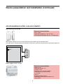
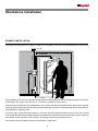
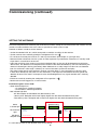
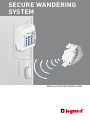
Secure WANDERING
system
1
4
7
C
2
5
8
0
3
6
9
E
INSTALLATION AND USAGE GUIDE
Contents
2
2
Installation principle
System description
3Device presentation and
installation
3
Secure wandering system
6Secure wandering system - auxiliary elements
7Standalone installation
7
Example installation
9Wiring - controllers and antennae
10Operating modes
11SYSTEM installation
11 Example installation
13Wiring - controller/antennae and door unit
14Operating modes
15Commissioning
15 Factory settings
16Parameter setting
18Adjusting the antennae
19Operation
19 Operation in day mode (surveillance)
20Operation in night mode (intruder)
21Illuminated signals
22
22
Characteristics
23
23
Usage codes
Specifications
Control code
Installation principle
SYSTEM DESCRIPTION
Safety instructions
Operation
This product must be installed in accordance with the
installation regulations and preferably by a qualified
electrician. Incorrect installation and operation may
lead to the risk of electric shock or fire. Read the
instructions and consider the product's specific
assembly location before carrying out the installation.
Do not open, remove, alter or modify the device unless this
is specifically stated in the instructions. Legrand products
must be opened and repaired exclusively by personnel
trained and authorised by Legrand. Any unauthorised
opening or repair voids all liability, replacement rights and
warranties.
Only use Legrand brand accessories.
The secure wandering system is a system that allows
any potential escape attempts by confused patients to
be controlled.
Each exit under surveillance is fitted with a standalone
controller which alerts staff when a person wearing a
special wristband tries to go through it. In the event that
there are no supervisory staff near the exit this information
can be transmitted to the BUS/SCS nurse call unit using a
door unit Cat. No. 766 06 configured for this function.
This way nurses receive information on the escapee's
identity and on the door used.
The system can operate using two modes:
• Surveillance mode: An alarm is activated when the
wearer of a wristband is close to the exit and this exit
is open.
• Intruder mode: An alarm is activated when an exit
is opened
Switching from one mode to the other is done manually by
entering a special code into the controller keypad.
The staff have a chaperone code which allows a wristband
wearer to be let through an exit under surveillance
without triggering an alarm.
Operating environment
- This device complies with the directives related to
exposure to radioelectric frequencies when used under
the normal conditions described in the user manual.
Follow the installation instructions described in the
manual.
- Depending on the configuration, this device regularly
transmits radio frequency radiation, the frequency and
power of which comply with ARCEP recommendations.
Using it in an industrial or hospital environment does
not generally pose any problem. However, using it
close to certain sensitive electronic systems may lead
to interference. Please ensure that installation of this
device is limited when in close proximity to any other
electronic equipment.
Two control outputs allow:
• The exit to be locked once a wristband is detected in the
vicinity (provide an electromagnetic lock*).
• An audible or illuminated warning signal to be triggered
when an escape alarm is activated.
* Product to be ordered separately (see p. 4)
2
Device presentation and installation
SECURE WANDERING SYSTEM
This system is used to signal crossing of a door threshold by a resident fitted with a wristband Cat. No. 766 20.
It works with door unit Cat. No. 766 06 configured for secure wandering and allowing acknowledgement.
Door controller Cat. No. 766 22
Technical characteristics
IP 20 - IK 04
• Operating temperature:
0°C to +45°C
• Power supply:
- 12 V=
- 500 mA
• Illuminated signals:
- System power on
- Intruder mode
- Wristband detection
• Audible signals:
- Alarm
- Alarm suppressed by chaperone code
• Functions that can be accessed via the keypad:
- Reset alarms
- Chaperone
- Changeover between surveillance/intruder modes
- System parameter settings
• Controller inputs:
- Adjustable connection
- Volt-free contacts
- Voltage detection
5-24 V=
50 mA to 24 V=
- Door contact (NO/NC)
- Chaperone contact (NO)
- Alarm acknowledgement (NO/NC)
- Mode selection
- Panic alarm (NO)
• Volt-free contact outputs:
- Locking: 1 A - 24 VA/60 V= max
- Alarm: 1 A – 24 VA/60 V= max
• Cable type for link with door unit (system solution):
2 x 9/10th pairs
1
2
1
4
7
C
2
5
8
0
3
6
9
E
3
4
5
6
1 Wristband activation magnet
2 Detection LED
3 Status LED
4 Coded keypad
5 Enter key
6 Cancel key
Normally situated close to the exit, this controller is the
heart of the system.
All auxiliary elements are connected to it.
A 12-button keypad is used to configure and
activate special functions (mode changes, alarm
acknowledgement, etc.).
A buzzer acts as a warning if an escape is detected.
The door controller retrieves the information from antenna
Cat. No. 766 21 and from door contact Cat. No. 431 00 and,
depending on its usage mode, either triggers a nurse call
or locks the door.
When the door is locked it can be unlocked using special
codes.
The coded keypad captures the wristband signal when a
predefined door is crossed.
Requires a modular 12 V= power supply
(Cat. No. 4 131 05).
3
Device presentation and installation (continued)
SECURE WANDERING SYSTEM (CONTINUED)
Antenna Cat No. 766 21
1
2
1 Status LED
2 Detection LED
Placed as close to the exit as possible, ideally 50 cm from the ground at the side of the door latch, this element detects the
presence of a wristband Cat. No. 766 20 and informs the controller Cat. No. 766 22.
The sensitivity and therefore the detection radius (around 1 to 15 m) can be set easily using a screwdriver.
A green indicator light indicates that the antenna power is on.
A red indicator light flashes when a wristband is in the detection zone (see setting the antenna).
The antenna activity is permanently checked by the controller.
Technical characteristics
• Power supply: via door controller Cat. No. 766 22
• Dimensions (H x W x D): 50 x 100 x 40 mm
• Screwed onto the wall
• IP 20 - IK 04
• Operating temperature: +0°C to +50°C
• Cable type (to controllers 766 22): 2 x 9/10th pairs
4
Wristband Cat. No. 766 20
Activated or deactivated
by passing a magnet
over the device.
To be performed close
to the controller
Cat. No. 766 22.
Worn on the wrist or the ankle, this waterproof wristband is fitted with eyelet closures preventing the person under
surveillance from taking it off.
These wristbands are made of anti-allergy plastic that is capable of being in continuous contact with the skin.
The battery has an expected lifetime of more than one year (although replacing the batteries every year is
recommended).
The weatherproof seal (IP 55) allows residents to take baths and showers.
The wristbands can also be cleaned by placing them in an alcohol bath for 5 minutes.
Wristbands must be removed in the following cases:
- If they are faulty or the battery is dead
- When the resident leaves
- When the resident undergoes an MRI (magnetic resonance imaging) exam
To remove the wristband, cut it with a pair of round-end scissors.
When a wristband is immobile it switches to low-consumption mode. This allows the standalone capacity of the battery
to be increased to a maximum 4 years when stored.
Once movement is detected the wristband switches immediately to operational mode.
Technical characteristics
• IP 55 - IK 08
• Anti-allergy
• Frequency: 869.85 MHz
• Tx: 869.85 MHz - Rx: 446.525 MHz
• Radiated power: < 10 mW
• Power supply: 1 x CR2450 3 V battery
• Standalone operation: 18 months with normal usage
• Dimensions (mm): 33 x 40 x 17
• Weight: 28 g in working order
5
Device presentation and installation (continued)
SECURE WANDERING SYSTEM - AUXILIARY ELEMENTS
Door contact Cat. No. 431 00
Technical characteristics
• IP 41 - IK 02
• Operating temperature: -10°C to +70°C
• Cable type (to controllers 766 22): 1 x 9/10th pairs
The magnetic opening sensor must be connected to the "door" input of controller 766 22.
An escape alarm is only generated on the double condition that a wristband and opening of the door are both detected.
766 22
DOOR
Sensor
Power supply Cat. No. 4 131 05
Technical characteristics
• Power: 15 W
• Operating voltage: 12 V
• Current: 1,25 A
• Dimensions: 5 x 17.5 mm modules
• Cable type (to controller 766 22):
2 x 1.5 mm2
• Class II
• Double operating terminal
• Protected by PTC against overloads and
short‑circuits
6
Standalone installation
EXAMPLE INSTALLATION
The diagram below represents a typical installation for a standalone system (ie. not connected to the nurse call unit).
4 131 05
2 x 1.5 mm2
1 x 9/10th pair
1
2
3
4
5
6
7
8
9
T
0
E
766 20
766 21
≈ 0.5 m
≈ 1.20 m
2 x 9/10th pairs
766 22
431 00
766 21
1 - 15 m
The controller Cat. No. 766 22 is normally installed in the immediate vicinity of the exit at a height that allows easy access
to the keypad. The antenna Cat. No. 766 21 is installed at a height of around 50 cm.
If the exit under surveillance is very wide (between 1 to 15 metres) two antennae placed on either side of the passageway
can be connected to the same controller. This avoids having to set the antenna sensitivity too high, which risks wristbands
being detected in adjoining rooms.
As with any radio system the antenna position is crucial for wristband detection performance and it must be installed
carefully. Equally, wherever possible wristbands must be placed in an identical manner on all residents under surveillance
(for example, on the right wrist if the antenna is to their right when they go through the exit).
The maximum distance between antenna and controller is 200 metres.
7
Standalone installation (continued)
EXAMPLE INSTALLATION (CONTINUED)
Outdoor installation:
The secure wandering system is not intended for outdoor installation. However, surveillance of this type of exit is
possible where the installation is adapted:
- The controller must be installed indoors.
- The antenna boxes must be placed in weatherproof enclosures made from non-conductive materials
(plastic, PVC, etc.).
- The enclosure must be protected from direct sunlight to avoid the risk of high internal temperatures.
Selecting a release or lock:
• Door release: flush-mounted installation
- Cable type (to controller 766 22): 2 x 1.5 mm2
- Cat. No. 408 95: 12 V= - 600 mA undervoltage door release - for operation at emergency exits
- Cat. No. 408 98: 12 V±/= - 500 mA shunt trip door release
• Electromagnetic lock: surface-mounted installation
- Cable type (to controller 766 22): 2 x 1.5 mm2
- Cat. No. 767 07: 300 kg lock
- Cat. No. 767 08: 500 kg lock
8
WIRING - CONTROLLERS AND ANTENNAE
766 22
431 00
ST7
ST1
1
1
ALARM
DOOR
LOCK
ST2
1
CHAPERONE
ST3
ST4
1
1
ALR
CLR
NL
1
CONF
ST5
1
IN
EX
4 131 05
DCIN
ST6
SW4
1
1 234
MODE
UGA
047 60
766 21
ST1
766 21
ST1
DS2
DS4
SW1
ST2
DS2
DS4
SW1
ST2
P3
P4
9
P3
P4
Standalone installation
OPERATING MODES
Chaperone
Mode selection
The controller must be set to chaperone mode in
order to allow a wristband wearer to go through an exit
without setting off the alarm.
This is done by entering a code on the keypad or by
activating the chaperone input (via a pushbutton or
keyswitch, etc.).
The chaperone contact must be normally open or normally
non-powered (rest mode).
The changeover from surveillance mode to intruder
mode and back can be controlled by the state of this
input. When the contact is open (or the input is not
supplied with power) the system is in surveillance
mode. When the contact is closed (or the input is
supplied with power) the system is in intruder mode.
The system state can therefore be controlled by an external
device (clock etc.).
When this input is not being used, the changeover from
one mode to the other is achieved by entering a code on
the keypad (see parameter setting).
Acknowledgement
When an alarm is detected, the alarm output and the
buzzer remain active until they are acknowledged.
The alarm is acknowledged by entering a code on the
keypad or by activating the acknowledgement input.
The acknowledgement is processed with each change of
state for this input.
The acknowledgement contact may therefore be of any
type whatsoever (NO/NC or powered/non-powered).
10
System installation
Example installation
The diagram below represents a typical installation for a BUS/SCS system (ie. connected to the nurse call unit).
4 131 05
2 x 1.5 mm2
2 x 1.5 mm2
1 x 9/10th pair
766 07
431 00
766 22
1
2
3
4
5
6
7
8
9
T
0
E
766 20
≈ 0.5 m
766 21
2 x 9/10th pairs
2 x 9/10th pairs
≈ 1.20 m
766 06
766 21
1 - 15 m
The system installation allows the escape to be signalled on the BUS/SCS nurse call unit Cat. No. 766 06 and this way the
information can be forwarded to DECT and tracing (see the BUS/SCS nurse call unit guide).
The controller Cat. No. 766 22 is normally installed in the immediate vicinity of the exit at a height that allows easy access
to the keypad. The antenna Cat. No. 766 21 is installed at a height of around 50 cm.
If the exit under surveillance is very wide (between 1 to 15 metres), two antennae placed on either side of the passageway
can be connected to the same controller. This avoids having to set the antenna sensitivity too high, which risks wristbands
being detected in adjoining rooms.
As with any radio system the antenna position is crucial for wristband detection performance and it must be installed
carefully. Equally, wherever possible wristbands must be placed in an identical manner on all residents under surveillance
(for example, on the right wrist if the antenna is to their right when they go through the exit).
The maximum distance between antenna and controller is 200 metres.
11
System installation (continued)
EXAMPLE INSTALLATION (CONTINUED)
Outdoor installation:
The secure wandering system is not intended for outdoor installation. However, surveillance of this type of exit is
possible where the installation is adapted:
- The controller must be installed indoors.
- The antenna boxes must be placed in weatherproof enclosures made from non-conductive materials
(plastic, PVC, etc.).
- The enclosure must be protected from direct sunlight to avoid the risk of high internal temperatures.
Selecting a release or lock:
Door release: flush-mounted installation
- Cable type (to controller 766 22): 2 x 1.5 mm2
- Cat. No. 408 95: 12 V= - 600 mA undervoltage door release - for operation at emergency exits
- Cat. No. 408 98: 12 V±/= - 500 mA shunt trip door release
• Electromagnetic lock: surface-mounted installation
- Cable type (to controller 766 22): 2 x 1.5 mm2
- Cat. No. 767 07: 300 kg lock
- Cat. No. 767 08: 500 kg lock
12
WIRING - CONTROLLER/ANTENNAE AND DOOR UNIT
ST1
1
766 22
ST7
ST1
1
1
ST2
766 06
431 00
ALARM
DOOR
LOCK
ST2
1
CHAPERONE
ST3
15 16 17 18 19 20
ST4
1
1
ALR
CLR
1
CONF
ST5
ST3
1
1
P5
NL
IN
EX
DCIN
4 131 05
ST6
SW4
1
1 234
MODE
047 60
UGA
766 21
ST1
DS2
DS4
SW1
ST2
DS4
SW1
ST2
P3
13
766 21
DS2
P4
P3
P4
System installation (continued)
OPERATING MODES
Chaperone
Mode selection
The controller must be set to chaperone mode for a
set time period (chaperone period) in order to allow a
wristband wearer to go through an exit without setting
off the alarm.
This is done by entering a code on the keypad or by
activating the chaperone input (via a pushbutton or
keyswitch, etc.).
The chaperone contact must be normally open or normally
non-powered.
For optimum security the controller returns to surveillance
mode once the door is opened and closed. The chaperone
period is cancelled.
The changeover from surveillance mode to intruder
mode and back can be controlled by the state of this
input. When the contact is open (or the input is not
supplied with power) the system is in surveillance
mode. When the contact is closed (or the input is
supplied with power) the system is in intruder mode.
The system state can therefore be controlled by an
external device (clock etc.).
When this input is not being used, the changeover from
one mode to the other is achieved by entering a code on
the keypad.
Acknowledgement
When an alarm is detected the alarm output and the
buzzer remain active until they are acknowledged.
Acknowledgement is via the door unit Cat No. 766 06
by pressing the nurse presence button.
14
Commissioning
FACTORY SETTINGS
For the initial commissioning or following a software update or restoration of the default settings (code 9090) the
controller is started up with the standard operating settings which have the following values:
• Controller address: 1
• Chaperone period: 15 seconds
• Door contact operation: Normally Closed (value 0)
• Door contact time delay: 5 seconds
• Chaperone code: 217
• Acknowledgement code: 369
• Buzzer volume: 2
• Mode selection (surveillance/intruder) via wire input (value 0)
• Locking control: Lock (value 0)
• Direction detection: Deactivated
• Surveillance of the radio elements: Activated (value 0)
• User language: French
• System link protocol: 2G anti-wandering system
• No code filtering (surveillance for all wristbands)
15
Commissioning (continued)
PARAMETER SETTING
The parameters can easily be set for the system using simple codes that provide access to the different
parameter setting steps.
A parameter setting is changed by entering the following on the controller keypad:
• 1 - The setting code (90XX codes)
• 2 - E (confirmation)
• 3 - The setting value
• 4 - E (confirmation)
• C: for cancelling an entry being made.
Important: The system must be in parameter setting mode before codes are entered on the keypad. There are
two ways of doing this:
- By placing a magnet under the controller.
- By entering the access code in the keypad parameter setting mode (9039E). This code is only taken into
account if the locking configuration (CONF) is at position "1.2" (factory position 2 and 3) .
An entry in parameter setting mode is confirmed by an audible signal from the controller lasting 2 seconds.
The system remains in parameter setting mode for 2 minutes and then returns automatically to normal mode.
Entering a valid configuration code extends this period by 2 minutes.
The system remains completely functional in parameter setting mode.
Code:
Parameter
9001
Chaperone period: Period during which the controller will not detect an alarm after a chaperone code
is entered. This period can be set between 1 and 255 seconds.
Example: Chaperone period of 45 s: 9001 E 45 E
Once the door has been opened and closed the controller returns to surveillance mode and the
chaperone time is cancelled.
9002
Chaperone code: Code that must be entered when the system is in surveillance mode in order for the
exit to be crossed with a wristband without an alarm being triggered. This code can be between 1 and
5 digits long. Avoid using codes that start with "90" so as to avoid any of the parameter settings being
changed by mistake.
Example code 12345: 9002 E 12345 E
9003
Acknowledgement code (standalone mode only): Code that must be entered in order to
acknowledge an alarm and stop the buzzer from sounding. This code can be between 0 and 4 digits
long.
Example code 456: 9003 E 456 E
9004
Buzzer volume: Sound level of the buzzer output in the event of an alarm. 0 = no audible signal,
1 = medium volume (75 dB A at 10 cm), 2 = high volume (85 dB A at 10 cm).
Example: Setting the buzzer to medium volume.: 9004 E 1 E
16
Code
Parameter
9005
Mode change mechanism: Allows the user to choose whether the changeover from intruder mode to
surveillance mode is performed by entering codes on the keypad (value 1) or by analysing the mode
selection input (value 0).
Example: Mode selection by entering codes on the keypad: 9005 E 1 E
9006
Locking control: Operation with locking control (value 0) or with release control (value 1).
Example: Electric release connected to the locking control: 9006 E 1 E
9009
Surveillance activation for the radio receivers: Enable (value 1) or disable (value 0) this function.
The green indicator light flashes when this option is enabled and the link with a radio receiver is broken.
Example: Disabling the radio surveillance function: 9009 E 0 E
9010
Adding a wristband number to the surveillance chart: Adds the number stated to the list of
wristbands to be kept under surveillance. The chart may contain 50 numbers.
Example: Adding the number 123 to the list of wristbands to be kept under surveillance: 9010 E 123 E
9011
Deleting a wristband number from the surveillance chart: Removes the number stated from
the chart of numbers under surveillance. If the number to be removed is 0 then all the numbers are
deleted.
If there are no numbers in the chart then the system is open, i.e. detections from all the wristband
numbers are acknowledged.
Example: Deleting the number 123: 9011 E 123 E
Example: Deleting the chart: 9011 E 0 E
9012
Door contact: Using a normally closed (value 0) or normally open (value 1) door contact.
Example: Connecting a normally open door contact: 9012 E 1 E
9013
Setting a time delay for the door contact: Period in seconds that the door contact is still considered
active following its return to the initial status. This period can be programmed for between 1 and 30
seconds. This period is equal to 5 seconds by default.
Example: 10-second time delay: 9013 E 10 E
9014
Immediate restart for the alarm: When this option is confirmed (value 1) an escape alarm can be
restarted immediately following acknowledgement of the alarm. Otherwise the wristband has to leave
the detection zone for at least 20 seconds before a new escape alarm is possible again from this
number.
Example: Immediate restart for authorised alarm: 9014 E 1 E
17
Commissioning (continued)
SETTING THE ANTENNAE
Due to the low power level radiated by the wristband transmitters setting the sensitivity level of the antenna must be
carried out under conditions that are as close as possible to normal system usage.
Proceed as follows in order to set the antenna:
• Set the thumbwheel SW1 to 8, which corresponds to medium sensitivity for the receiver.
• Set the antenna to test mode by placing the configurator ST2 to 2-3
• Fit a wristband in exactly the manner as is worn by the residents (for example, on your right wrist)
• Remove all other wristbands from the system in order to prevent any interference. Place them in standby mode
or put them in a metal box or enclosure.
• Adjust the sensitivity of the antenna using the thumbwheel SW1 so that you will be detected once inside the
desired area. The detection and reception level in relation to the threshold defined by SW1 are indicated by the
antenna indicator lights flashing (see below). Make allowance for a safety margin in order to ensure detection
even if a wristband's radio range is altered (if an unusual obstacle is present for example).
The value 0 corresponds to the receiver's minimum sensitivity level, i.e. the transmitter must be very close
in order to be detected (in the order of a few centimetres). The higher the thumbwheel value the greater the
detection distance. The value F corresponds to the acknowledgement of any signal received that is correctly
decoded.
• Exit the test mode by resetting the configurator ST2 to position 1-2
• Perform one or more trigger tests in normal mode
Illuminated signals in test mode.
• Greenindicator light DS4
- On continuously: Awaiting reception
- Off for 200 ms: Receiving wristband
• Redindicator light DS2
- Off: No reception or level below that determined by SW1
- 100 ms pulse: Reception with a level slightly higher than the threshold determined by SW1
- Two 100 ms pulses: Reception with a level much higher than the threshold determined by SW1
Recommended
detection zone
Green
indicator light
Red indicator
light
Wristband
reception level
Switch to
test mode
Switch to
normal mode
Detection threshold
It is advisable to mark out the detection zone on the ground.
18
Operation
Operation in day mode (surveillance)
This mode is activated using code 9031 or a timing device connected to the "MODE" terminals.
The controller must generate an alarm in the event that a resident fitted with a wristband escapes.
When in rest mode, the power supply indicator light is on constantly and the operation indicator light is permanently off.
The alarm output is active and the locking output inactive.
If a wristband that is on the surveillance list is detected by one of the antennae, this status is signalled by the operation
indicator light flashing slowly. The locking control is also activated if the system is programmed in lock mode. This status is
maintained for 5 seconds following the last detection of the wristband.
If the door is opened while a wristband is detected, the alarm contact changes state, the buzzer is activated and the
operation indicator light flashes (see the diagram on p.21). This status is maintained until the alarm is acknowledged.
Acknowledgement is achieved by typing the acknowledgement code into the keypad or by activating the
acknowledgement contact connected to the controller. This causes the audible signal to stop and the alarm contact
returns to rest mode. The wristband related to the escape that has been acknowledged must be out of the detection zone
for 30 seconds (factory setting) before an escape alarm from this transmitter can be processed again.
The controller must be set to chaperone mode in order to allow a wristband wearer to go through an exit without
setting off the alarm. This is achieved by typing the chaperone code into the keypad or by closing the chaperone contact
connected to the controller. The operation indicator light flashes quickly and the buzzer sounds at the same rate. The lock
output is now inactive even if a wristband has been detected. The exit can be crossed with a wristband without an alarm
being triggered while the controller is in chaperone mode. The controller returns to surveillance mode at the end of a
time delay or when the door is closed (see time delay code for the door contact 9013).
19
Operation (continued)
OPERATION IN NIGHT MODE (INTRUDER)
This mode is activated using code 9030 or a timing device connected to the "MODE" terminals.
This mode is used when the controller needs to generate an alarm if the exit is opened or crossed by anyone (with or
without a wristband).
When in rest mode, the power supply indicator light is on and the function light emits 2 brief pulses every 10 seconds.
The alarm output is active and the lock output is also active if the system is in lock mode.
If a wristband worn by a resident is detected by one of the antennae, this status is signalled by the operation indicators
light flashing slowly.
If the door is opened, the alarm relay is released, the buzzer activated and the function light flashes (see the
diagram on p. 21). This status is maintained until the alarm is acknowledged.
This acknowledgement is achieved by typing the acknowledgement code into the keypad or by activating the
acknowledgement contact connected to the controller. This causes the audible signal to stop and the alarm output to be
reactivated.
The controller must be set to chaperone mode in order to allow someone to cross the exit under surveillance without
the alarm being triggered. This is achieved by typing the chaperone code into the keypad or by closing the chaperone
contact connected to the controller. The operation indicator light flashes quickly and the buzzer sounds at the same rate.
The lock output is now inactive. The controller returns to intruder mode at the end of the adjustable time delay.
20
ILLUMINATED SIGNALS
The controller status is indicated via two indicator lights.
When the green indicator light is on constantly the system is switched on. Flashing indicates that there is a system fault
which requires the controller and the antennae to be checked.
The yellow operation indicator light shows the system status with different types of flashing (see the diagram below).
Intruder mode
Detection
Chaperone
Intruder alarm
Escape alarm
Panic alarm
5s
10s
21
15s
Characteristics
SPECIFICATIONS
Power supply:
• 12 to 24 V=
• 150 mA
Volt-free contact outputs:
• Locking: 1 A - 24 VA/60 V= max
• Alarm: 1 A – 24 VA/60 V= max
Illuminated signals:
• System power ON
• Intruder mode
• Wristband detection
Wristband:
• Frequency: 869.85 MHz
• Radiated power: < 10 mW
• Power supply: 1 x CR2450 3 V battery
• Standalone operation: 18 months with normal usage
• Dimensions (mm): 33 x 40 x 17
• Weight: 28 g in working order
• Sound level
- Volume = 1
75 dB (A) at 10 cm
- Volume = 2
85 dB (A) at 10 cm
Audible signals:
• Alarm
• Alarm suppressed by chaperone code
Functions that can be accessed via the keypad:
• Alarm reset
• Chaperone
• Changeover between surveillance/intruder modes
• System parameter setting
Controller inputs:
• Adjustable connection
- Volt-free contacts
- Voltage detection
> 5-24 V=
> 50 mA to 24 V=
• Door contact (NO/NC)
• Chaperone contact (NO)
• Alarm acknowledgement (NO/NC)
• Mode selection
• Panic alarm (NO)
22
Usage codes
Control CODE
Option of changing the operating mode by entering a code.
A parameter setting is changed by entering the following on the controller keypad:
• 1 - Enter the code
• 2 - E (validation)
- C: permet d’annuler une saisie en cours.
Code
Control
9030
Switch to night mode (intruder)*
9031
Switch to day mode (surveillance)*
9039
Switch to parameter setting mode: This code is only taken into account if the locking configuration
(ST8) is at position "1-2" (factory position 2-3) .
9090
Parameter loading by default: Deletion of all current parameter settings and return to default
parameter settings. The code 9090 must be entered twice in order to prevent incorrect operation.
Example: 9090 E 9090 E
9098
Listing of the system parameter settings: Transmission of the entire settings to the controller
system link.
0000
Controller reset: Resets the controller in the same way as a return of power. The code 9999 must be
set in the parameters in order for this to be taken into account.
Example: 0000 E 9999 E
*When operating mode selection via the keypad is activated each changeover from one mode to another is
memorised. If the power supply is cut, the controller starts up in the last mode that was activated.
The controller starts up in surveillance mode for the initial commissioning.
23
LE04653AB-EN
Head office:
128, av. du Maréchal-de-Lattre-de-Tassigny
87045 Limoges Cedex - France
Tel: +33 5 55 06 87 87
Fax: +33 5 55 06 88 88
www.legrand.com