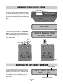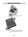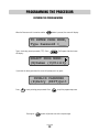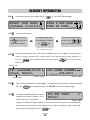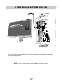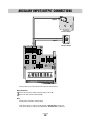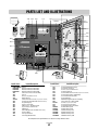
1
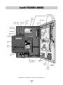
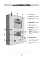
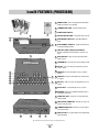
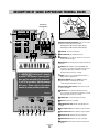
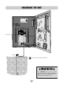
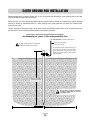
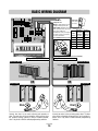
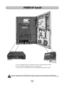
The Chamberlain Group, Inc.
845 Larch Avenue
Elmhurst, Illinois 60126-1196
www.liftmaster.com
IC ON2 6 S E RI E S
TELEPHONE ENTRY SYSTEM
OWNER’S MANUAL
www.liftmaster.com
TABLE OF CONTENTS
Product Overview . . . . . . . . . . . . . . . . . . . . . . . . . . . . . . . . . . . . . . . . . . . . . . . . . . . . . . . . . . . . . . . . . . . . . . . . . . . . . 3
Resident Use . . . . . . . . . . . . . . . . . . . . . . . . . . . . . . . . . . . . . . . . . . . . . . . . . . . . . . . . . . . . . . . . . . . . . . . . . . . . . . . 4-7
Icon26 Features (Inside) . . . . . . . . . . . . . . . . . . . . . . . . . . . . . . . . . . . . . . . . . . . . . . . . . . . . . . . . . . . . . . . . . . . . . . . . 8
Icon26 Features (Outside) . . . . . . . . . . . . . . . . . . . . . . . . . . . . . . . . . . . . . . . . . . . . . . . . . . . . . . . . . . . . . . . . . . . . . . 9
Icon26 Features (Processor) . . . . . . . . . . . . . . . . . . . . . . . . . . . . . . . . . . . . . . . . . . . . . . . . . . . . . . . . . . . . . . . . . . . 10
Mounting Installation . . . . . . . . . . . . . . . . . . . . . . . . . . . . . . . . . . . . . . . . . . . . . . . . . . . . . . . . . . . . . . . . . . . . . . . . . 11
Description of Surge Suppression Terminal Board . . . . . . . . . . . . . . . . . . . . . . . . . . . . . . . . . . . . . . . . . . . . . . . . . . . 12
Grounding the Unit . . . . . . . . . . . . . . . . . . . . . . . . . . . . . . . . . . . . . . . . . . . . . . . . . . . . . . . . . . . . . . . . . . . . . . . . . . . 13
Earth Ground Rod Installation . . . . . . . . . . . . . . . . . . . . . . . . . . . . . . . . . . . . . . . . . . . . . . . . . . . . . . . . . . . . . . . . . . 14
Basic Wiring Diagram . . . . . . . . . . . . . . . . . . . . . . . . . . . . . . . . . . . . . . . . . . . . . . . . . . . . . . . . . . . . . . . . . . . . . . . . . 15
Power-Up Icon26 . . . . . . . . . . . . . . . . . . . . . . . . . . . . . . . . . . . . . . . . . . . . . . . . . . . . . . . . . . . . . . . . . . . . . . . . . . . . 16
Postal Lock Installation . . . . . . . . . . . . . . . . . . . . . . . . . . . . . . . . . . . . . . . . . . . . . . . . . . . . . . . . . . . . . . . . . . . . . . . . 17
RS485 Wiring Configurations . . . . . . . . . . . . . . . . . . . . . . . . . . . . . . . . . . . . . . . . . . . . . . . . . . . . . . . . . . . . . . . . . . . 18
RS485 Daisy Chain Connection Example . . . . . . . . . . . . . . . . . . . . . . . . . . . . . . . . . . . . . . . . . . . . . . . . . . . . . . . . . . 19
RS485 Star Connection Example . . . . . . . . . . . . . . . . . . . . . . . . . . . . . . . . . . . . . . . . . . . . . . . . . . . . . . . . . . . . . . . . 20
Memory Card Installation . . . . . . . . . . . . . . . . . . . . . . . . . . . . . . . . . . . . . . . . . . . . . . . . . . . . . . . . . . . . . . . . . . . . . . 21
Warning and Precautions . . . . . . . . . . . . . . . . . . . . . . . . . . . . . . . . . . . . . . . . . . . . . . . . . . . . . . . . . . . . . . . . . . . . . . 22
Programming the Processor . . . . . . . . . . . . . . . . . . . . . . . . . . . . . . . . . . . . . . . . . . . . . . . . . . . . . . . . . . . . . . . . . . . . 23
Selecting Program Mode . . . . . . . . . . . . . . . . . . . . . . . . . . . . . . . . . . . . . . . . . . . . . . . . . . . . . . . . . . . . . . . . . . . . . . 24
Resident Information . . . . . . . . . . . . . . . . . . . . . . . . . . . . . . . . . . . . . . . . . . . . . . . . . . . . . . . . . . . . . . . . . . . . . . . . . 25
Transmitter/Card Programming . . . . . . . . . . . . . . . . . . . . . . . . . . . . . . . . . . . . . . . . . . . . . . . . . . . . . . . . . . . . . . . . . 26
Area Codes . . . . . . . . . . . . . . . . . . . . . . . . . . . . . . . . . . . . . . . . . . . . . . . . . . . . . . . . . . . . . . . . . . . . . . . . . . . . . . . . . 27
Utility Codes . . . . . . . . . . . . . . . . . . . . . . . . . . . . . . . . . . . . . . . . . . . . . . . . . . . . . . . . . . . . . . . . . . . . . . . . . . . . . . . . 28
Password . . . . . . . . . . . . . . . . . . . . . . . . . . . . . . . . . . . . . . . . . . . . . . . . . . . . . . . . . . . . . . . . . . . . . . . . . . . . . . . . . . 29
Clock/Timer . . . . . . . . . . . . . . . . . . . . . . . . . . . . . . . . . . . . . . . . . . . . . . . . . . . . . . . . . . . . . . . . . . . . . . . . . . . . . . 30-32
Strike Time . . . . . . . . . . . . . . . . . . . . . . . . . . . . . . . . . . . . . . . . . . . . . . . . . . . . . . . . . . . . . . . . . . . . . . . . . . . . . . . . . 33
Talk Time . . . . . . . . . . . . . . . . . . . . . . . . . . . . . . . . . . . . . . . . . . . . . . . . . . . . . . . . . . . . . . . . . . . . . . . . . . . . . . . . . . 33
Greeting . . . . . . . . . . . . . . . . . . . . . . . . . . . . . . . . . . . . . . . . . . . . . . . . . . . . . . . . . . . . . . . . . . . . . . . . . . . . . . . . . . . 34
Volume Adjustment . . . . . . . . . . . . . . . . . . . . . . . . . . . . . . . . . . . . . . . . . . . . . . . . . . . . . . . . . . . . . . . . . . . . . . . . . . 34
Back-Up Memory . . . . . . . . . . . . . . . . . . . . . . . . . . . . . . . . . . . . . . . . . . . . . . . . . . . . . . . . . . . . . . . . . . . . . . . . . . . . 35
Error Messages . . . . . . . . . . . . . . . . . . . . . . . . . . . . . . . . . . . . . . . . . . . . . . . . . . . . . . . . . . . . . . . . . . . . . . . . . . . . . 36
Display Controller Board . . . . . . . . . . . . . . . . . . . . . . . . . . . . . . . . . . . . . . . . . . . . . . . . . . . . . . . . . . . . . . . . . . . . . . . 37
Large Display Battery Back-Up . . . . . . . . . . . . . . . . . . . . . . . . . . . . . . . . . . . . . . . . . . . . . . . . . . . . . . . . . . . . . . . . . . 38
Auxiliary Input/Output . . . . . . . . . . . . . . . . . . . . . . . . . . . . . . . . . . . . . . . . . . . . . . . . . . . . . . . . . . . . . . . . . . . . . . . . . 39
Optional Camera . . . . . . . . . . . . . . . . . . . . . . . . . . . . . . . . . . . . . . . . . . . . . . . . . . . . . . . . . . . . . . . . . . . . . . . . . . . . . 40
Parts List and Part Illustrations . . . . . . . . . . . . . . . . . . . . . . . . . . . . . . . . . . . . . . . . . . . . . . . . . . . . . . . . . . . . . . . . . 41
Approvals . . . . . . . . . . . . . . . . . . . . . . . . . . . . . . . . . . . . . . . . . . . . . . . . . . . . . . . . . . . . . . . . . . . . . . . . . . . . . . . . . . 42
To be installed by Qualified Dealers ONLY!
Icon26 manual
version 3.0
Icon Page
1
Icon Page
2
PRODUCT OVERVIEW
STANDARD FEATURES
• Twenty Six line Large LC Directory.
– Names listed on Directory in alphabetical order.
– 10” LCD screen Sunlight readable and backlit for low light
applications.
• Memory capacity: 250, 500, 1000 names.
• User-friendly programmability via built-in alpha-numeric
keyboard eliminates the need for user's manual.
• Four character alpha-numeric password required to enter
programming mode.
• Programmable Utility key codes for keyless entry.
– 60 Utility key codes available per system.
– Time zones associated with Utility key codes.
• Programmable real-time clock with leap year & daylight savings
compensation.
• 2 programmable 7-day timers for door and gate control.
• Programmable talk time.
• Touch-tones through microphone are ignored by system.
• System mutes tones in speaker during dialing.
• Postal lock capability with programmable strike time.
• Surge protection;
– 6000V, 3000A
– Power input port
– Telephone line port
– RS485 ports
– Relay ports
– Input port
– Immune to 25,000V electrostatic discharge.
• Two output relays with independent strike times.
• Relay output for VCR time lapse recorder to record 5 seconds
per transaction.
• (Optional) camera for security monitoring (High resolution color)
• 32-Device zone control:
– 32 programmable “Groups”.
– 32 programmable 7-day timer “Templates”.
• Standard I/O board with 3 auxiliary inputs controlling 3 corresponding relays.
• Power failure backups:
– Battery backup for complete function for 3 hours.
– Battery enables dial out, program, & display.
– Non-Volatile removable SRAM memory has unlimited
write cycles (unlike EEPROM).
– Non-Volatile Real Time Clock/Calendar.
• High quality voice communication system with background
noise filtering.
• Voice messages (digital) to help & guide user.
• Programmable volume level via modem.
• Non-Volatile PCMCIA memory card
• Two (2) slots for PCMCIA memory cards. Second slot used for
file backup and/or (Optional) “Remote Access Communicator
Card”.
• Double box with built-in full keyboard for data processing.
• By pressing '9' for gate or '5' for door, communication is not lost.
Talk time is extended to avoid unpleasant cutoff between visitor
and resident.
• Both DTMF tone and rotary dial detection.
• (Optional) modem.
• Remote programming via modem using “Elite Pro” windows
based software.
• FCC part 68 ,15 & Canadian DOC approval.
• ETL approved UL 294, UL 1950
SPECIFICATIONS
• Construction: Front and Back Panel: 16 gauge stainless steel.
Processor Containment Box: Gold/zinc plated, powder
coated aluminum (weather resistant finish)
• Entire system is rain resistant.
• Power Input: 12 Vac, 50VA UL listed transformer.
• Operating Environment:
– Temperature: Icon26: -4 F to +135 F
Icon26-HT: -4 F to +165 F
(Heater kit available at additional cost.)
– Relative Humidity: 5% - 95% non-condensing.
• Dimensions: 16" W X 20 1/2" H X 4 3/4" D
• Shipping Weight: Approximately 40 lbs.
• Display protected by heavy duty,anti-reflection scratch resistant glass.
3
2
1
6
5
4
9
8
7
P
0
O
I
HE
ROGR
M
EXIT
Q
D
S
A
SHIFT
X
J
H
G
F
W
ER
Y
T
R
E
ASE
U
P
N ER
V
N
L
K
M
’
CK
P CE
B
C
Z
R
E BA
SPAC
3 Year Warranty
Factory to Dealer
Icon Page
3
RESIDENT USE
The Icon26 System will start and default back to the
“Welcome To” screen (fig a.).
(fig a.)
Use the
button for assistance. (fig b.).
(fig b.)
Use the
keys to access the residence list
in the Icon26’s electronic directory as shown in (fig c.).
The names are listed in alphabetical order by last name.
(fig c.)
Icon Page
4
RESIDENT USE CONTINUED
When the desired name is found, enter the corresponding
STATUS
3-digit code. The system will dial the number assigned to
the resident code entered. (fig d.)
(fig d.)
After connecting, the screen will display the “Talk Time”
STATUS
screen as shown in (fig e.) If the resident wants to allow
access to the visitor, they simply press (or dial) “9” for
vehicular gate entrances, or “5” for door or pedestrian
gate .
(fig e.)
The “Access Granted” screen will appear (fig f.). If the res-
STATUS
ident wants to deny access, they simply hang up the phone.
(fig f.)
Icon Page
5
RESIDENT USE CONTINUED
Entry 1 –
Entry 2 – Door or Pedestrian Gate
Vehicular Gate
By pressing or dialing the number “9” on their digital
or rotary phone,
By pressing or dialing the number “5” on their digital
or rotary phone,
OR
OR
The resident will open the vehicular entrance gate.
The resident will open the door or pedestrian gate.
USING KEY CODES AND UTILITY CODES
(ACTIVE ENTRY ONLY)
RESIDENT 6-DIGIT KEY CODES
STATUS
Residents are assigned a 6-digit, personalized key code for
accessing the facility. To use the key code assigned, the
resident must first push the
key once and enter
their key code. The screen will display “Access Granted”
(fig a.) and access will be allowed. If an incorrect key code
is entered (con’t. next page)
(fig a.)
Icon Page
6
RESIDENT USE CONTINUED
If an incorrect key code is entered, the system will
STATUS
inform the user of the invalid entry (fig b.) The resident
can then re-enter their key code.
(fig b.)
EXAMPLE - KEY CODE 002543 =
0
INDIVIDUAL UTILITY CODES
0
2
5
3
4
STATUS
All systems, no matter what the memory capacity, are
equipped with 60 different Utility codes. To access the
facility within the time zone set, the Utility Company must
first press the
key TWICE and then enter their 4-
digit code. If it is within the programmed time zone for
entry, the screen will display “Access Granted” (fig a.)
and access will be allowed. If, however, it is not within the
time zone for entry, the display will inform the user and
access will not be allowed (fig c.)
(fig c.)
EXAMPLE - UTILITY CODE 8716 =
8
Icon Page
7
7
1
6
Icon26 FEATURES (INSIDE)
Large Display
Contrast Adjustment
Large Display Power Switch
Processor Key
Release / Lock
Processor
Power
Switch
Mounting
Holes (4)
Camera
(Optional)
Power
Backup
Unit
Microphone
Cooling
Fan
Memory Card
Release Buttons
Memory Card
Memory Card
Slot
Knock-Out
LC Display
12V
AC DC
)
)
D
POWER N
COM
NC
NO
COM
NC
NO
Processor
Unit
V DEO
OUT
C
NO
EL L NE GT
REL
N
GND
)
)
D
/ EXI
HRELA
YU
VCR
DOOR
RELA
Y
Key
Lock
CHASS S
GROUND
CAMERA
Dialing
Keys
Y that this unit is properly
R
e provided "chassis ground"
ro
connected to the ground
rod
grounded, lightning damage
eas refer to the owners
ease
or
proper
grounding
r u c t i o n s
el teent yphone com
Programming
Keys
AN
F
KBRD
Y
IRELA
U
MADE N USA
TE
A GA
RELA
Y
RELA
Y
DOOR
P
Surge Suppressor
Terminal Board
Postal Lock
Setup
External
Keypad
External
Speaker
All components and specifications are subject to change without notice.
Icon Page
8
Stainless
Steel Door
Icon26 FEATURES (OUTSIDE)
13
5
1
2
6
7
1
EXTERNAL MICROPHONE
2
KEY LOCK - Opens the Processor Containment Box to access the Processor.
3
HELP KEY - With digital voice messages
to help guide the user.
4
EXTERNAL SPEAKER
5
DISPLAY WINDOW - Heavy-duty, protective lens.
6
KEYPAD LIGHTING - Lights
dialing keys for easy visibility.
7
PHONE DIALING KEYS - Used to dial residents / key codes
8
SCROLL KEYS - Scrolls through names in
alphabetical order on screen.
9
UNLOCK KEY - Residents and utility personnel use this key with their key code to
open gate.
10
HANG-UP KEY - Pressed when user
wants to hang up.
11
ACCESS FOR POSTAL LOCK
12
16 GAUGE STAINLESS STEEL DOOR Heavy-duty and weather resistant.
8
3
9
up
10
11
4
12
13 CAMERA (OPTIONAL) - For security monitoring.
All components and specifications are subject to change without notice.
Icon Page
9
Icon26 FEATURES (PROCESSOR)
1000
MEMORY CARD - Stores all programmed information.
(Different memory sizes available)
2
COMMUNICATOR CARD - Card for RS485 devices.
3
POWER ON/OFF SWITCH
4
CARD RELEASE BUTTONS - Eject Cards when pressed.
5
MAIN MEMORY CARD SLOT - Holds Main Memory
Card.
6
RS485 MEMORY CARD SLOT - Holds RF Communicator Card or Backup Memory.
7
TWO LINE, LARGE LIQUID CRYSTAL DISPLAY Displays information and instructions, two lines at a
time.
8
DIRECTION KEYS - Move cursor to desired position
within screens.
9
PROGRAM KEY - Sets Processor to the program mode.
Remote Access RS485
COMMUNICATOR CARD
500
250
capacity
1
2
4
5
6
1
Main Memory Card Slot
RS485 Memory Card Slot
3
7
10 EXIT KEY - Press this key to go back to the previous
screen / menu.
8
9
10
11
12
13
EXIT
ERASE
Q
SHIFT
W
A
E
S
Z
SPACE BAR
ENTER
PROGRAM
D
X
3
4
5
6
7
8
9
0
T
F
C
2
HELP
R
Y
G
V
11 ERASE KEY - Erases information screens no longer
needed.
1
U
H
B
I
J
N
K
M
L
’
14
12 ENTER KEY - Registers information into memory after
it is typed.
15
13 HELP KEY - Helps user while in programming or user
modes.
P
O
BACK
SPACE
14 SCROLL KEYS - Scrolls through screens / menus.
15 KEYBOARD - Works like standard keyboard to type in
information and names.
16 PHONE JACK (RJ11) - Connects to surge suppressor
terminal board.
17 INPUT/OUTPUT CONNECTOR - Connects to surge suppressor terminal board.
18 COMMUNICATION PORT - Connects to surge suppressor terminal board.
19
18
17
19 PARALLEL PORT - To communicate with Large Display
Controller Board.
16
All components and specifications are subject to change without notice.
Icon Page
10
MOUNTING INSTALLATION
Installation on Wall
Remove the Processor Unit from the Processor Containment Box and bolt the Processor Containment Box to the recess in the
wall using the four mounting holes. Feed the power and phone lines through the knockout in the back of the box to make all
wire connections.
Mounting Holes (4)
3 1/4"
3/4
9 1/2"
"
Wall
2 1/8"
13"
2O
2C
2OM
O
C
OM
ND
2N
Wire
Knock
Out
AUX
OTPT REAYS
12V
C/C
AUX
NPT
O
OM
+)
()
ND
C
O
OWER N
+)
()
GND
S85 3)
VIEO
OUT
RS48 (1)
+)
()
ND
GE
EY
TL LNE N
N
ND
RS48 (2)
Wire
Knock
Out
OOR
EAY
VC
VO
+)
()
GND
S85 4)
CHSSS
GROND
PSTL
SWTH
/
EX
IPU
CMER
VCR
ELY
t s MANDATORY that his unit i poperly
grounded The provided "chassi ground"
wire must be connected to he grund rod
f unit is not grounded lightnn damage
will occur Please refer to th owners
manual for proper gounding nstuctons
5 1/2"
ltenrphnecm
AN
KRD
LGT
MADE N USA
AU
RE
UX 2
ELY
GAE
RLAY
DOR
RLAY
8 3/8 "
3 7/8"
Front View
Side View
201/2"
NOTE: Be sure to install the unit at normal eye level.
16"
4 3/4 "
Be sure to read and follow all LiftMaster Elite instructions before installating and operating any LiftMaster Elite
products. LiftMaster Elite is not responsible for improper installations or failure to comply with local building codes.
All components and specifications are subject to change without notice.
Icon Page
11
DESCRIPTION OF SURGE SUPPRESSION TERMINAL BOARD
2-NO
2-NC
2-COM
1-NO
1-NC
1-COM
GND
2-IN
1-IN
Knockout for
Incoming Wires
2
(+)
(-)
GND
RS-485 (1)
(+)
(-)
GND
(+)
(-)
GND
RS-485 (2)
RS-485 (3)
RS-485 (4)
3
POWER IN
4
5
Removable Screw Terminal Connectors for Easy Wiring.
1 AUX OUTPUT RELAYS/AUX INPUT: Inputs can be used for
COM
NC
NO
COM
NC
NO
(+)
(-)
GND
Postal Lock and/or Exit switch operations.
VIDEO
OUT
TEL LINE IN
V-C
V-NO
AUX
INPUT
IN
GND
7
12V
AC/DC
GATE
RELAY
2 POWER IN: 12 Vac to the Entry Phone.
CHASSIS
GROUND
9
Auxiliary Input 1-IN activates auxiliary Relay 1
Auxiliary Input 2-IN activates auxiliary Relay 2
DOOR
RELAY
CAMERA
POSTAL / EXIT VCR
SWITCH INPUT RELAY
12V
AC/DC
AUX
OUTPUT RELAYS
6
POWER IN
1
8
3 TELEPHONE LINE: Tip and Ring Connection.
11
4 GATE RELAY: For use with gate operator to control access
through main vehicular gate.
10
5 DOOR RELAY: For allowing access through pedestrian gate
or door.
6 VIDEO OUT: Camera video output standard BNC cable
connection for use with time lapse VCR. Each time access
is granted, the VCR relay is activated for 5 seconds,
allowing recording of all access to facility.
It is MANDATORY that this unit is properly
grounded. The provided "chassis ground"
wire must be connected to the ground rod.
If unit is not grounded, lightning damage
will occur. Please refer to the owners
manual for proper grounding instructions.
7 RS485: Connect to corresponding RS485 terminals (-, +,
GND) of remote security devices.
8 CHASSIS GROUND: Entry Phone MUST be properly
grounded. Refer to “Grounding the Unit” and
“ Earth Ground Rod Installation” sections.
9 POSTAL SWITCH/EXIT SWITCH : Connection of a postal
lock or exit switch.
10 VCR RELAY: For use with time lapse VCR. Each time
MADE IN USA
access is granted, the VCR relay is activated for 5 seconds,
allowing recording of all access to facility.
11 CAMERA PORT: For optional camera video input.
12 FAN LED: Indicates fan is activated.
13 KEYBOARD LIGHT LED: Indicates keyboard lights have
FAN
KBRD
LIGHT
AUX 1
RELAY
AUX 2
RELAY
GATE
RELAY
DOOR
RELAY
power.
POWER
14 AUX 1 RELAY LED: Indicates auxiliary 1 relay is activated.
15 AUX 2 RELAY LED: Indicates auxiliary 2 relay is activated.
12
13
14
15
16
17
18
16 GATE RELAY LED: Indicates gate relay is activated.
17 DOOR RELAY LED: Indicates door relay is activated.
18 POWER LED: Indicates Phone system has 12 Vac power
Icon Page
12
present.
-NO
-NC
-COM
-NO
-NC
-COM
ND
-N
GROUNDING THE UNIT
NO
COM
NC
NO
+)
-)
GND
RS 485 (2)
COM
+)
-)
GND
RS 485 4)
POWER N
VIDEO
OUT
TEL L NE N
N
GND
+)
-)
GND
RS 485 (1)
RS 485 3)
Chassis Ground
12V
AC/DC
AUX
NPUT
+)
-)
GND
V-C
V-NO
AUX
OUTPUT RELAYS
GATE
RE A
DOOR
R LAY
HASS S
ROUND
CAMERA
FAN
KBRD
L GHT
AUX 1
RE AY
AUX 2
R LAY
GATE
RELAY
DOOR
RE AY
P W R
Ground Rod
Refer to the next page for ground rod installation.
It is MANDATORY that this unit is properly
grounded. The provided "chassis ground" wire
must be connected to the ground rod. If unit is not
grounded, lightning damage will occur.
Icon Page
13
EARTH GROUND ROD INSTALLATION
Proper grounding gives an electrical charge, such as from an electrical static discharge or a near lightning strike, a path from
which to dissipate its energy safely into the earth.
Without this path, the intense energy generated by lightning could be directed towards the Telephone Entry System. Although
nothing can absorb the tremendous power of a direct lightning strike, proper grounding can protect the Telephone Entry
System in most cases.
The type and length of earth ground rods vary by region. Contact the building inspector’s office in the municipality where you
plan to install the unit for correct grounding materials and installation procedures.
Before digging, contact local underground utility locating companies.
Avoid damaging gas, power, or other underground utility lines.
to the “Chassis Ground” of Telephone Entry System
For the correct wire gauge,
consult the local code
The earth ground rod must be located within
3 feet from the Telephone Entry System.
The ground wire must be a single, whole piece of
wire. Never splice two wires for the ground wire.
If you should cut the ground wire too short,
break it, or destroy its integrity, replace it with a
single wire length.
For the correct depth
consult the local code
Not responsible for improper installation
or failure to comply with all necessary
local building codes.
For the correct diameter, consult the local code
Icon Page
14
BASIC WIRING DIAGRAM
2-NO
2-NC
2-COM
1-NO
1-NC
1-COM
GND
2-IN
1-IN
TIP
RING
12V
AC/DC
(+)
(-)
GND
RS-485 (1)
(+)
(-)
GND
(+)
(-)
GND
RS-485 (2)
VIDEO
OUT
TEL LINE IN
IN
GND
RS-485 (3)
POWER IN
RS-485 (4)
COM
NC
NO
COM
NC
NO
(+)
(-)
GND
TIP
RING
AUX
INPUT
V-C
V-NO
AUX
OUTPUT RELAYS
Transformer
12 Vac (50VA)
Telephone Line:
(Provided)
MUST be a dedicated line for the
Telephone Entry System unit
ONLY! NOTE: Installation where
Polarity does not matter
fiber optic phone lines are present
12 Vac
16.5 Vac
may require additional
(50 VA)
(50 VA)
modifications from your telephone
Maximum Maximum
Wire
provider. Contact your provider
Distance
Distance
Gauge (Provided)
(Optional)
for more information.
30 Ft
50 Ft
Use 18 AWG wire where possible 24 AWG
GATE
RELAY
DOOR
RELAY
CHASSIS
GROUND
CAMERA
POSTAL / EXIT VCR
SWITCH INPUT RELAY
85 Ft
20 AWG
75 Ft
135 Ft
18 AWG
125 Ft
220 Ft
16 AWG
185 Ft
345 Ft
Removable Screw Terminal Connectors for Easy Wiring.
Entry 1 Gate Relay Terminal Connection
Normally Open
Vehicular Gate
45 Ft
12V
AC DC
POWER IN
It is MANDATORY that this unit is properly
22 AWG
Entry 2 Door Relay Terminal Connection
Normally Closed
Pedestrian Gate
Conduit
Conduit
Maglock
Master Gate Operator
(Strike Open Input)
OR
Access Door
OR
Solenoid
Entry Door
Maglock
Dial
Dial
Connect two wires to the main vehicular gate operator or
door. The gate relay will be activated by either pressing 9 on
the resident's phone, entering a utility or resident keycode,
Gate 7-day timer or ElitePro remote programming software.
Icon Page
15
Connect two wires to the secondary gate or door. The door
relay will be activated by either pressing 5 on the resident's
phone, Door 7-day timer or ElitePro remote programming
software.
POWER-UP Icon26
FAN
KBRD
L GHT
A
R
AUX 2
R LAY
GA E
RELAY
DOOR
R LAY
P
Processor
Power Switch
Large Display
Power Switch
1. Turn on large display using the “LCD power” switch on the battery back-up module.
2. Turn on processor using the power switch on the top right.
3. To turn unit off, turn off both processor and large display battery back-up module.
Be sure to read and follow all LiftMaster Elite instructions before installing and operating any LiftMaster Elite
products. LiftMaster Elite is not responsible for improper installations or failure to comply with local building codes.
Icon Page
16
POSTAL LOCK INSTALLATION
These parts are used only when postal access to your facility is required. The postal lock mechanism must be obtained by application
to your local post office.
Postal Lock
Switch Assembly
Stainless Steel
Front Panel of
Entry Phone
Switch Assembly
Mounting Holes
(Mount with Postal
Lock on Entry Phone
Front Panel)
Postal Lock
Side View
Postal Lock
Switch Assembly
Postal Lock
Switch Wires (2)
AN
BRD
L GHT
AU
RE
AUX 2
R LAY
GA E
R LAY
OR
RE AY
Switch Assembly
Mounting Holes
Front View
2-NO
2-NC
2-COM
1-NO
1-NC
1-COM
GND
2-IN
1-IN
Installation:
(+)
(-)
GND
RS-485 (2)
1
Open the front panel of the Telephone Entry System and remove the hole plug.
2
(Retain nuts and washers) Install the postal lock with the sliding bolt oriented
away from the speaker.
3
Install the enclosed plate end switch assembly over the sliding bolt so that
when the bolt is extended it will activate the switch as shown in the diagram.
4
Fasten by using the enclosed flat washer, lock washer, and nut on each of the
four studs. Adjust the plate and switch location as the nuts are tightened to
ensure switch activation when the bolt is extended.
5
Connect the two wires from the postal lock switch to the postal/exit connector
on the surge suppressor terminal board. Note that polarity or color coding is
not required. When the postal lock is engaged, the system’s gate relay is
activated for a duration according to the programmed “Gate Strike Time”.
6
Test operation by activating the lock. Ensure that full extension of the sliding
bolt will not bend or break the switch.
COM
NC
NO
COM
NC
NO
(+)
(-)
GND
POWER IN
TIP
RING
(+)
(-)
GND
RS-485 (1)
IN
GND
(+)
(-)
GND
RS-485 (3)
RS-485 (4)
12V
AC/DC
AUX
INPUT
VIDEO
OUT
TEL LINE IN
V-C
V-NO
AUX
OUTPUT RELAYS
GATE
RELAY
DOOR
RELAY
CHASSIS
GROUND
POSTAL / EXIT VCR
SWITCH INPUT RELAY
CAMERA
It is MANDATORY that this unit is properly
grounded. The provided "chassis ground"
wire must be connected to the ground rod.
If unit is not grounded, lightning damage
Icon Page
17
RS485 WIRING CONFIGURATIONS
“Daisy Chain” wiring configuration
Configuration #1
(Recommended method for superior data transmission)
• Up to 31 RS485 devices supported
• Maximum distance from the last RS485 device to the Telephone Entry System is 4000 Ft.
• Turn “ON” the terminator switch ONLY for the last device installed in the RS485 line.
• Use 22 AWG twisted pair shielded wire
Turn Terminator Switch “ON”
for Last Device on Wire Run
Gnd
+
–
4000 Ft Max.
Each RS485 device must have a unique “Device ID Number” set by using the rotary switches on the device. (Refer to specific RS485 Instruction sheets).
Configuration #2
“Star” wiring configuration
• Maximum number of wire runs allowed is 7
Turn Terminator Switch “ON”
for Last Device on Wire Run
Turn Terminator Switch “ON”
for Last Device on Wire Run
• Maximum number of RS485
devices present on ALL wire runs
is 31.
4000 Ft Max.
• Maximum distance from the last RS485 device
(per wire run) to the Telephone Entry Syetem is
4000 Ft.
– + Gnd
Wire Run
Turn Terminator Switch “ON”
for Last Device on Wire Run
• Use 22 AWG twisted pair shielded wire
Turn Terminator Switch “ON”
for Last Device on Wire Run
Turn Terminator Switch “ON”
for Last Device on Wire Run
Turn Terminator Switch “ON”
for Last Device on Wire Run
Turn Terminator Switch “ON”
for Last Device on Wire Run
Each RS485 device must have a unique “Device ID Number” set by using the rotary switches on the device. (Refer to specific RS485 Instruction sheets).
Icon Page
18
2-NO
2-NC
2-COM
1-NO
1-NC
1-COM
GND
2-IN
1-IN
RS485 DAISY CHAIN CONNECTION EXAMPLE
Main M
AUX
INPUT
(+)
(-)
GND
(+)
(-)
GND
RS485 (1)
(+)
(-)
GND
(+)
(-)
GND
RS485 (2)
RS485 (3)
ard Slot
RS485 Memory Card Slot
RS485 Card Release Button
12V
AC/DC
AUX
OUTPUT RELAYS
RS485 (4)
POWER IN
COM
NC
NO
COM
NC
NO
capacity
VIDEO
OUT
TEL LINE IN
V-C
V-NO
COMMUNICATOR CARD
IN
GND
Remote Access RS485
GATE
RELAY
DOOR
RELAY
CHASSIS
GROUND
POSTAL / EXIT VCR
SWITCH INPUT RELAY
CAMERA
NOTE: To support RS485 devices you must insert the RF
communicator card in the RS485 memory card slot
BEFORE turning on the processor.
It is MANDATORY that this unit is properly
grounded. The provided "chassis ground"
wire must be connected to the ground rod.
If unit is not grounded, lightning damage
f r to the owners
Gnd
–
+
Use 22 AWG Twisted Pair Shielded Wire
+
–
Gnd
Keypad
RS485 Remote
Device 1
+
–
Gnd
+
–
Gnd
Stand-Alone Receiver
RS485 Remote
Device 2
Card Reader
RS485 Remote
Device 3
Icon Page
19
Universal Interface Board
RS485 Remote
Last Device
1-COM
GND
2-IN
1-IN
12V
AC/DC
Remote Access RS485
COMMUNICATOR CARD
capacity
YS
)
)
(+)
(-)
GND
RS485 (1)
( )
()
ND
(+)
(-)
GND
RS485 (2)
Main M
Card Slot
POWER IN
VIDEO
OUT
TE
IN
GN
RS485 (3)
RS485 Memory Card Slot
AUX
INPUT
COM
NC
NO
COM
NC
NO
AU
OUTPUT
RS485 (4)
GATE
RELAY
NE IN
V-C
V NO
2-NO
2-NC
2-COM
RS485 STAR CONNECTION EXAMPLE
DOOR
RELAY
CHASSIS
GROUND
RS485 Card Release Button
POSTAL / E
SWITCH INP
NOTE: To support RS485 devices you must insert
the RF communicator card in the RS485 memory
card slot BEFORE turning on the processor.
It i
gro
wi
If u
MANDATOR
ded. The p
must be con
t is not gro
CAMERA
VCR
RELA
hat
vide
cte
ded
s unit is properly
"chassis ground"
o the ground rod.
ightning damage
r to the owners
Gnd
–
+
Gnd
–
+
+
Gnd
Keypad
RS485 Remote
Device 3
–
–
+
Gnd
Stand-Alone Receiver
RS485 Remote
Device 4
Card Reader
RS485 Remote
Device 2
Use 22 AWG Twisted Pair Shielded Wire
Icon Page
20
Universal Interface Board
RS485 Remote
Device 1
MEMORY CARD INSTALLATION
Main Memory Card Slot
Turn power on and insert Memory Card into Main Memory Card Slot (Main Memory Card in back slot, Backup
Memory Card in front slot.) (fig a.) Push it all the way in
until card “snaps” into place and the release button pops
up. The screen should display the “Welcome Screen”
(fig b.)
RS485 Memory Card Slot
Main Memory Card Release Button
(fig a.)
WELCOME
(fig b.)
If the screen continues to display the “Insert Memory
Card” screen (fig c.) then eject memory card by pressing the corresponding release button down and reinsert
Memory Card into main slot (fig d.). Otherwise continue with programming.
Insert Memory Card
IN MAIN SLOT
(fig c.)
Push Button
Card Pops Out
(fig d.)
VIEWING THE SOFTWARE VERSION
Memory Capacity
To view the memory capacity of the system or to view
the software version currently running on the system in
operation an information screen is accessible on all
Dial Code systems for easy reference. Turn power off
and insert Memory Card in Main Memory Slot. Turn
power on and the information screen should display as
seen in (fig e.)
DIAL CODE LC-250
REV. 1.00_
(fig e.)
Software Version Number
Icon Page
21
WARNINGS AND PRECAUTIONS
500
Do not touch the terminals on the RAM Cards.
Do not bend, drop or expose to impact.
3
2
1
6
5
4
9
8
7
P
0
O
I
U
P
HEL
ER
ENT
RAM
R
G
PRO
EXIT
E
SE
Q
A
T
SHIF
CE
SPA
D
S
X
J
H
G
F
W
ERA
Y
T
V
N
L
K
M
’
K
BACCE
SPA
B
C
Z
BAR
The Telephone Entry System is only water resistant when the Stainless Steel Door is closed and locked. Do not expose the Processor
Unit or the open Processor Containment Box to rain, snow, or harsh
weather conditions. Do not drop the Processor or expose it to
impact.
Icon Page
22
PROGRAMMING THE PROCESSOR
ENTERING THE PROGRAM MODE
When the Processor unit is turned on and the
button is pressed, the screen will display:
TO ENTER PROG MODE,
Type Password >____
Type in the factory present password (7777). Press
will display:
. The Program Selection Screen
SELECT PROG MODE:
(N)Names (U)Utility
If you enter the wrong password, the screen will prompt you to try again:
INVALID PASSWORD
(R)Retry (EXIT)Quit
Press
R
to retry entering your password. Press
Pressing the
to quit the programming menu.
button will provide users with a help message.
Icon Page
23
SELECTING PROGRAM MODE
LIST OF PROGRAM MODES:
1
Names
N
Program or edit Resident Names
2
Utility
U
Program or edit Utility Codes
page 28
3
Password*
P
Program New Password ( recommended )
page 29
4
Clock/Timer
C
Program System Clock and Seven Day Timers
5
Strike Time
S
Program relay output time ( for 2 relays )
page 33
6
Talk TIme
T
Program length of Talk Time
page 33
7
Greeting
G
Program custom Welcome Screen Message
page 34
8
Volume
V
Program Volume level
page 34
9
Backup
B
Backup of memory card
page 35
page 25-27
pages 30-32
*We recommend you customize your password to avoid unauthorized programming (see “Password” section)
To select a Program Mode, press the corresponding letter from one of the nine options.
Use the
keys to scroll through the nine different Program Modes.
SELECT PROG MODE:
(N)Names (U)Utility
SELECT PROG MODE:
(T)Talk Time
SELECT PROG MODE:
(P)Password
SELECT PROG MODE:
(G)Greeting
SELECT PROG MODE:
(C)Clock/Timer
SELECT PROG MODE:
(V)Volume (B)Backup
SELECT PROG MODE:
(S)Strike Time
Pressing the
button will provide users with a help message.
IMPORTANT NOTE: While in the help screens, programming will be disabled.
To continue programming, press the
button to exit the help screens first.
Icon Page
24
RESIDENT INFORMATION
STEP
1
In the Program Selection Screen (fig a.), Press the
SELECT PROG MODE:
(N)Names (U)Utility
N
key. The screen will display (fig b.):
PROG A NEW NAME
PROG BY CODE:___
(fig a.)
STEP
2
N
(fig b.)
You now have three options:
To program by name, press
the
N
key and the first
empty code will display.
To program by code, enter
OR
a three digit code* and press
the
To view or edit an existing name
OR
key.
or code, use the
keys to scroll through Directory.
* The unit will only accept codes within it’s
range - depending on memory capacity.
STEP
3
Type in the desired Resident name, LAST name first, followed by the first name (fig c.). If the code you have
selected is already used, there will be a name already. You can edit the name by simply typing over it.
Press the
key to complete the entry. You may also use the
keys to move the cursor
within a code.
Resident code
005 LastNAME,First
Jones, Robert_
Resident name
STEP
STEP
005 PHONE NUMBER:
_-___-496-2634
(example - fig c.)
(example - fig d.)
4
Type in the desired Resident phone number (fig d.). If you need to enter an area code refer to the area code page.
5
An individual six digit Resident Key code may be
Press the
key to complete the entry. The “KEY CODE” screen will be displayed. (fig e.)
005 KEY CODE:
005123
assigned to each resident . Residents can use
their Key Code to access the premises.
(example - fig e.)
Assignment of Resident Key Codes is optional. The first three digits of the Key Code is the assigned Directory
Code. Assign the last three digits (numeric characters only) to create an individual Key Code. If using the RF
Card, proceed to Step 6 (fig e.). Press the
key.
Icon Page
25
TRANSMITTER/CARD PROGRAMMING
STEP
6
To complete entry, press the
key to return to the program selection screen.
To program RF devices ( i.e. transmitters/cards etc.) continue on to Step 7.
NOTE: To enable the transmitter/card programming feature, you must insert the communicator card
in the “backup” slot before you turn on unit. (refer to “Memory Card Installation” section)
STEP
7
Use
keys to view and
005 TRANSM/CARD#1:
___-_____ (S) SCAN
program up to 10 transmitter or card
codes associated to the directory code.
005 TRANSM/CARD#2:
___-_____ (S) SCAN
To program a transmitter or card code
you may enter the code manually using
the keypad or you may scan the
••
••
transmitter/card code.
STEP
8
005 TRANSM/CARD#10:
___-_____ (S) SCAN
To scan a card code, press and release
the
S
key and activate the card
as shown in fig a.
Touch the card to the card reader
to activate remote device
Model ECR485B
To scan a transmitter code, press and
S
release the
(fig a.)
key and activate
the transmitter as shown in fig b.
EX T
ERASE
Q
SH FT
SPACE BAR
ENTER
ROGRAM
W
A
E
S
Z
X
3
5
6
7
8
Y
G
V
9
(fig b.)
0
T
F
C
2
4
HELP
R
D
1
U
H
I
J
N
B
M
L
’
Processor
STEP
9
P
O
K
BACK
SPACE
er
STAND-ALONE
RECEIVER
Model ERRB485
Press button on transmitter to activate remote device
Repeat steps 7 and 8 for up to ten devices per directory code. After the last device has been programmed,
press
or
key to return to the program selection screen.
NOTE: The time zones and restrictions associated with transmitter/card codes can only be programmed remotely using the
EMS modem software.
Icon Page
26
AREA CODES
005 PHONE NUMBER:
_-___-___-____
PREFIX FIELD
AREA CODE FIELD
(fig a.)
In special applications, it is necessary to enter area codes for Resident Phone Numbers. Area codes are
entered from the Phone Number screen (fig a.).
005 PHONE NUMBER:
1-___-___-____
(fig b.)
Use the
key to enter the area code and prefix field (fig b.). The Prefix defaults to “1” for normal
11-digit dialing. Where necessary, you can change the prefix to any number. To choose 8, 9, or 10-digit
dialing, when no prefix is needed, press
while in the prefix field. Then type the required
number of digits in the area code field followed by the phone number. Press the
key to
continue with the entry as described in the “Resident Information” section.
To erase “Resident” information, press the
key. Press the
key for assistance.
IMPORTANT NOTE: While in the help screens, programming will be disabled.
To continue programming, press the
button to exit the help screens first.
Icon Page
27
UTILITY CODES
A 4-digit Utility Code (numeric characters only) may be assigned to “Utility Companies” such as delivery, telephone, construction companies, water, power, etc. These utilities can use their individual code to access the premises
within the time zone that you program. Each system, no matter what the memory capacity, is equipped with 60
available Utility Codes and time zones.
STEP
1
In the Program Selection Screen (fig a.),
U
Press the
SELECT PROG MODE:
(N)Names (U)Utility
key. The screen will
display (fig b.):
STEP
2
(fig a.)
You now have two options:
PROG UTILITY CODE> N
View/Edit Codes >
(fig b.)
To program a new Utility Code, press
N
the
key and type in a 4 digit
code. If the code entered is used, type
Use the
or edit existing Codes. The last screen
OR
will display memory spaces available.
in another.
STEP
3
Press the
Select a code that you wish to edit.
key or the
UTILITY CODE:4762
NAME:FedEx
key to enter code. Type the name of the
utility in the screen that follows and
press the
keys to view
(example - fig c.)
key or
(fig c.).
STEP
4
Enter the desired time zone in the
4762 TimeZone
09:00AM To 05:00PM
screen that follows (fig d.)
Use the
keys to move the
(example - fig d.)
cursor. To view the previous screen, use
the
key. Press the
key to complete your transaction.
For “User Mode” operation, Refer to the “Resident Use” Section.
To erase “Utility” information, press the
key. Press the
key for assistance.
IMPORTANT NOTE: While in the help screens, programming will be disabled.
To continue programming, press the
button to exit the help screens first.
Icon Page
28
PASSWORD
The factory present password is 7777. We suggest that you customize it.
In the Program Selection Screen (fig a.), Press the
P
SELECT PROG MODE:
(P)Password
key.
(fig a.)
To customize a password, type in a four character
password (it may be alphanumeric characters).
Press the
NEW PASSWORD:
****
key to enter the new
password. It will be displayed by asterisk (*) for
security (fig b.) (To leave the password
unchanged, press the
(fig b.)
key.)
A confirmation screen will appear (fig c.). Type in
the same password and press the
RE-ENTER PASSWORD:
****
key.
If you enter a different password, the password will
not be confirmed and you will have to repeat the
(fig c.)
transaction.
Always remember your password! This password is required to enter the Program Mode. If you
lose your password, you will need to contact the manufacturer to reissue a new password.
Pressing the
button will provide users with a help message.
IMPORTANT NOTE: While in the help screens, programming will be disabled.
To continue programming, press the
button to exit the help screens first.
Icon Page
29
CLOCK/TIMER
The Clock/Timer allows you to set the date and time, and to program gates and doors to be opened or closed whenever
specified. This clock is equipped with 100 year calender, auto leap year compensation and daylight savings.
In the Program Selection Screen (fig a.), Press the
C
SELECT PROG MODE:
(C)Clock/Timer
key.
(fig a.)
Use the
PROG CLOCK/TIMER
(1)Date & Time
keys to scroll between
the three different menu choices (fig b.). Select the
number of your choice or press the
PROG CLOCK/TIMER
(2)Gate Timer
key while on the selection of your choice.
CAUTION: Make sure to set the Date and Time
before programming the clock timers for the
door and gate.
PROG CLOCK/TIMER
(3)Door Timer
(fig b.)
1. DATE AND TIME
Use the
1
the
key to set the Date and time, use
DATE>02-11-2000
Time>07:31am p=pm
keys to move the cursor. Press the
key to enter your input.(fig c.)
Use the
(fig c.)
Today Is THURSDAY
Use
To Select Day
keys to select the
current day of the week. Press the
key
to enter your input. (fig d.)
Select daylight savings by pressing
yes or
N
for no. The
(fig d.)
Y
for
Daylight Savings>y
(Y)Yes (N)No
key will
complete the date and time entry. (fig e.)
(fig e.)
Icon Page
30
CLOCK/TIMER CONTINUED
2./ 3. DOOR AND GATE TIMERS
Press
2
3
to program Gate Timers Menu. Press
to program the Door Timers Menu.
Setup New Timers> N
View/Edit Timers>
Use
See next page for instructions
USE ARROWS TO VIEW / PROGRAM
INDIVIDUAL TIME ZONES
SUN G Tmr1: ON F=off
07:00am -> 05:00pm
to view and program timer(s) for
Sunday through Saturday. Move the cursor
to time and type in the setting. Two timers can be set
MON G Tmr1: ON F=off
08:00am -> 04:30pm
for each day of the week following the procedure below.
(fig a.)
••
•
SAT G Tmr1: ON F=off
07:00am -> 05:00pm
(fig a.)
Program timers 1 and 2 for any day of the week (fig b. & c.)
Press
N
to turn timer 1 ON or press
F
to
turn timer 1 OFF. Press the
key. Type the
desired timer 1 setting. For am type
A
type
P
Press
SUN G Tmr1: ON F=off
07:00am -> 05:00pm
(fig b.)
For pm
SUN G Tmr2: ON F=off
07:00am -> 05:00pm
to program the timer 2.
(fig c.)
To program the second timer, repeat the above procedure. Press the
key when complete.
To exit “Timers” screen, press the
key for assistance.
key. Press the
IMPORTANT NOTE: While in the help screens, programming will be disabled.
To continue programming, press the
button to exit the help screens first.
Icon Page
31
CLOCK/TIMER CONTINUED
2./ 3. DOOR AND GATE TIMERS, continued’
Press
2
to program Gate Timer Menu Press
3
to program the Door Timers Menu
PRESS N TO PROGRAM SETS OF
TIME ZONES
Setup New Timers> N
View/Edit Timers>
See previous page for instructions
Program timers 1 and 2 for any day of the week (fig d.)
Press
N
turn timer 1 OFF. Press the
. Press
to
(fig d.)
key. Type the
desired timer 1 setting. For am type
P
F
to turn timer 1 ON or press
GATE Tmr1: ON F=off
__:__am -> __:__pm
A
,For pm type
to program the timer 2.
GATE Tmr2: ON F=off
__:__am -> __:__pm
To program the second timer, repeat the above
procedure. Press the
key when complete.
Timer 1 & 2 settings can be copied to any day(s) of the
COPY Timers1,2 To
Workdays(y) Sun(n)
week. Select the day(s) of the week to be copied.
Press
Y
to select day or press
select day of week. Press
N
to not
COPY Timers1,2 To
Mon(n) Tue(n) Wed(n)
when complete.
(fig e.)
COPY Timers1,2 To
Thr(n) Fri(n) Sat(n)
(fig e.)
To exit “Timers” screen, press the
key. Press the
key for assistance.
IMPORTANT NOTE: While in the help screens, programming will be disabled.
To continue programming, press the
button to exit the help screens first.
Icon Page
32
STRIKE TIME
Strike Time sets the amount of time your gate or door relay will be held open.
In the Program Selection
SELECT PROG MODE:
(S)Strike Time
Screen (fig a.), Press the
S
key.
The strike time can be set for
Door Strike Time > D
Gate Strike Time > G
both gates and doors (fig b.)
Press the
D
(fig a.)
Press the
key to set the Door Strike Time. Type in
G
(fig b.)
key to set the Gate Strike Time. Type in
a time from 1 to 99 seconds (fig c.). Press the
a time from 1 to 12 seconds (fig d.). Press the
key to enter your selection.
key to enter your selection.
GATE STRIKE TIME:
[01-12] 05 Seconds
DOOR STRIKE TIME:
[01-99] 10 Seconds
(fig d.)
(fig c.)
GATE NAME/LOCATION
North Side Gate
DOOR NAME/LOCATION
South Entry Door
(fig f.)
(fig e.)
For either the Gate or Door Strike TIme, you may now type in a name and location (up to 13 characters) to which you want
the programmed strike time applied. (fig e.) and (fig f.) Press the
key to complete the transaction.
TALK TIME
You can set the amount of time to talk on the Entry Phone at 20, 40, or 80 seconds.
SELECT PROG MODE:
(T)Talk Time
TALKTIME IS 20 SEC
(B)40 Sec (C)80 Sec
(fig h.)
(fig g.)
In the Program Selection Screen (fig g.), Press the
B
for 40 seconds, or
C
T
key. Choose the desired Talk Time, press
for 80 seconds (fig h.). Press the
Icon Page
33
A
for 20 seconds,
key to confirm your entry.
GREETING
Use the Greeting Screen to customize the Welcome message.
In the Program Selection Screen (fig a.), Press
the
G
key.
SELECT PROG MODE:
(G)Greeting
(fig a.)
Type the name of the facility and press the
FACILITY NAME:
Woodbridge Meadows
key to complete your entry. The
system will automatically center your entry on
the Welcome screen.(fig b.)
(fig b.)
VOLUME ADJUST
Use the Volume Screen to adjust both call and unit message volume levels.
In the Program Selection Screen (fig c.), Press
the
V
key.
SELECT PROG MODE:
(V)Volume (B)Backup
(fig c.)
Use the
keys to adjust the
volume to the desired level (fig d.). Press the
key to complete the entry.
CALL VOLUME>
___________ +
(fig d.)
Volume at unit speaker for visitor/tenant
communication.
Use the
keys to adjust the
volume to the desired level (fig e.). Press the
key to complete the entry.
UNIT MSG VOLUME>
___________ +
(fig e.)
Unit messages. Ex: access granted, invalid
entry, etc.
Pressing the
button will provide users with a help message.
IMPORTANT NOTE: While in the help screens, programming will be disabled.
To continue programming, press the
button to exit the help screens first.
Icon Page
34
BACK-UP MEMORY
Main Memory Card Slot
RS485 Memory Card Slot
Back-Up Memory Card Release Button
(fig a.)
NOTE: You must have an extra memory card (sold separately)
installed in the RS 485 Slot (fig a.) of the Processor in order
to perform the backup process.
SELECT PROG MODE:
(V)Volume (B)Backup
In the Program Selection Screen (fig b.),
Press the
B
key.
Insert additional memory card in the
Backup Slot.
(fig b.)
NOTE: Back-up Memory card must be
the same size or greater than the Main
Memory card being backed up.
MAIN Card Updated On
05-15-01 03:50am
(fig c.)
The screens will display when the cards
were last updated. (fig c.) and (fig d.)
Use the
BACKUP Card Updated
02-11-01 04:20am
keys to scroll
through the information.
Press the
(fig d.)
key to Backup.
Press the
key to exit the backup
process (fig e.).
(ENTER) To Backup
(EXIT) To Quit
(fig e.)
Pressing the
button will provide users with a help message.
IMPORTANT NOTE: While in the help screens, programming will be disabled.
To continue programming, press the
button to exit the help screens first.
Icon Page
35
ERROR MESSAGES
OUT OF RANGE CODES: If the processor detects one
or more 3-digit codes present on the memory card
inserted that cannot be accessed, an error message is
displayed. (fig a.) Codes that cannot be accessed by
the limitation of the system being used cannot be
edited.
Codes Detected out
of Range, See Manual
(fig a.)
LOW BATTERY If the battery backup is reaching it’s
minimal charge level, a battery icon with a “B” next to
it will display in the top right corner of the
display. (fig b.) An alert beep will accompany this
icon. The batteries must be charged to continue.*
WELCOME
If the battery backup level reaches it’s minimal charge,
an error message will display (fig c.) and the system
will become non-functional until the battery backup is
charged by using the plug in transformer.*
Battery Is Low
It Must Be Recharged
B
(fig b.)
(fig c.)
LOW BATTERY ICONS: If a battery icon appears in
the top right corner of the display and the letter next
to it is an “M” or a “C”, as shown in (fig d.) and (fig
e.), contact Manufacturer for instructions.
WELCOME
C
(fig d.)
WELCOME
M
(fig e.)
*IMPORTANT NOTE: In order to charge the battery in the Dial Code System, the processor MUST be plugged in to the
transformer and the processor MUST BE ON. If the power is off on the processor, the battery will not be charging.
Icon Page
36
DISPLAY CONTROLLER BOARD
7
10
8
1
Display Contrast
Adjustment
2
Power Input
Overvoltage
3
Battery
BATT
Power
OVRV
BUSY
4
5
Power
POWER
11
9
LED Indicators
6
1
12 VAC Input
2
12 VAC Output - (Not used)
3
Battery - (On/Off switch input)
4
Input/Output
5
Comm Port - (Connected to processors parallel port)
6
Sensor Input
7
Large Display Contrast Adjustment (Clockwise-Lighter Contrast, Counterclockwise-Darker Contrast)
8
Batt
9
Power
10
OVRV
11
Busy
ON: System is working using battery power.
OFF: System is working using transformer power.
ON: System has power (Transformer, Battery).
OFF: System has no power (Transformer, Battery).
ON: Incorrect transformer voltage (Overvoltage).
OFF: Proper transformer voltage (Transformer plugged in).
ON: LED flashes when receiving data from processor.
OFF: No data being received from processor.
Icon Page
37
LARGE DISPLAY BATTERY BACK-UP
OVRV
BUSY
T-100 is a built-in battery back-up module for the Large Display Controller Board. It provides the system with 3
to 5 hours of battery operation.
NOTE: “LCD Power” switch must always be turned ON for large display to operate.
Icon Page
38
AUXILIARY INPUT/OUTPUT CONNECTIONS
Input 2
Postal Lock
Connection Example
1-IN
2-IN
Exit Switch
Connection Example
2-NO
2-NC
2-COM
1-NO
1-NC
1-COM
GND
2-IN
1-IN
GND
Input 1
(+)
(-)
GND
(+)
(-)
GND
RS-485 (2)
POWER IN
COM
NC
NO
COM
NC
NO
(+)
(-)
GND
RS-485 (1)
IN
GND
(+)
(-)
GND
RS-485 (3)
RS-485 (4)
12V
AC/DC
AUX
INPUT
VIDEO
OUT
TEL LINE IN
V-C
V-NO
AUX
OUTPUT RELAYS
GATE
RELAY
DOOR
RELAY
CHASSIS
GROUND
CAMERA
POSTAL / EXIT VCR
SWITCH INPUT RELAY
It is MANDATORY that this unit is properly
i
und"
Auxiliary inputs can be used for Postal Lock and/or Exit switch operations.
Wiring Instructions:
1 Connect one terminal of a switch to Auxiliary Input (1-IN, or 2-IN)
2 Connect the other terminal to Ground (GND).
Note:
Auxiliary Input 1-IN activates auxiliary Relay 1
Auxiliary Input 2-IN activates auxiliary Relay 2
Strike Time of Relay 1 is equal to the programmable “Gate Strike Time” of processor
Strike Time of Relay 2 are equal to the programmable “Door Strike Time” of processor
Icon Page
39
OPTIONAL CAMERA
1
Part # ICON26CAMERA
This compact, optional color camera is only 22 mm x 26 mm and is
capable of 10-bit DSP, 330 line resolution output.
1 Connect camera to surge suppression terminal board with cable
supplied with camera.
2 Connect a BNC cable from a time lapse recorder or monitor to the
Video Out connector on the surge suppression terminal board.
2-NO
2-NC
2-COM
1-NO
1-NC
1-COM
GND
2-IN
1-IN
For further detailed installation instructions please refer
to the installation sheet supplied with the camera.
(+)
()
GND
(+)
()
GND
RS 485 (2)
RS 485 (4)
COM
NC
NO
COM
NC
NO
(+)
()
GND
RS 485 (1)
POWER IN
N
GND
(+)
()
GND
RS 485 (3)
2
12V
AC DC
AUX
NPUT
VIDEO
OUT
TEL LINE IN
V-C
V-NO
AUX
OUTPUT RELAYS
GATE
RELAY
DOOR
RELAY
CHASSIS
GROUND
POSTAL / EXIT VCR
SWITCH INPUT RELAY
CAMERA
1
Icon Page
40
PARTS LIST AND ILLUSTRATIONS
T109 T010
T103
T135
T111
Icon
Camera
T150SPT
T011
T180
Remote Access RS485
COMMUNICATOR CARD
capacity
Memory
Card
T104
RS485
Card
T106
T020
T148
T030
T003
T029
2-NO
2-NC
2-COM
1-NO
1-NC
1-COM
GND
2- N
1- N
12V
AC/DC
AUX
OU PUT RELAYS
AUX
NPUT
+)
()
GND
(+)
(-)
GND
RS4 5 1)
+)
()
GND
(+)
(-)
GND
RS4 5 2)
VID O
OUT
T L L NE N
N
GND
RS 85 3)
POWER N
COM
NC
NO
COM
NC
NO
LC Processor
RS 85 4)
VC
V NO
T027
GATE
RE AY
DOOR
R LAY
T140
CHASS S
GROUND
CAMERA
POSTAL / EX T VCR
SW TCH INPUT RELAY
T025
It is MANDATORY
properly
ATORY that this unit is pr
grounded The
"chassiss gr
ground"
T e provided "chass
wire must be connec ed o the groun
ground rod
ot grounded lightning da
If unit is not
damage
will occur Please refer to the oowners
manual for proper grounding instructions
el teen ryph ne com
T137
T132
MADE IN U A
T032
AN
KBRD
L GHT
A
RE
AUX 2
RELAY
GATE
RELAY
DOOR
RELAY
P
T012SPT
T160
T114
T026
T000
T044
Icon26 Part #
ICON26CAMERA
RFCARD4K
RFCARD8K
RFCARD16K
T000
T003
T010
T011
T012SPT
T020
T025
T026
T027
T029
T030
T036
T044
T103
T104
Icon26 Description
Icon26 Part #
Camera
RS485 Communicator Card 4000
RS485 Communicator Card 8000
RS485 Communicator Card 16000
Transformer 12 Vac 50 VA (Provided)
Keylock
Processor Key Release / Lock
Battery Back-Up
9-Pin Comm Port Connector (Surge Protection Terminal)
LC Complete Internal Metal Box (Processor Box)
Programming Keys
Postal Lock Assembly
LCD Processor - No Memory Card
Key for Internal / External Lock
LCD Display
Heater Pad Option (Pre-Installed in Processor)
Speaker 4 OHM
Icon Keylock Bracket
Icon Display Window Glass
T106
T108
T109
T111
T114
T132
T135
T137
T140
T148
T150SPT
T160
T180
T25MEM
T50MEM
T150MEM
T250MEM
T500MEM
T1000MEM
Icon26 Description
Icon Display Window Assembly
Icon Stainless Steel Door
Icon Processor Containment Box
Icon Battery Back-Up
Icon External Box Connection Kit (Surge Protection Terminal)
Icon External Front Door, W/O Display
Icon LC External Box Assembly
Icon Keypad Light
GLCD Metal Keypad Complete W/ Lighting
Temp / Light Sensor Cable (GLCD)
Icon Fan (Surge Protection Terminal)
Icon Surge Protection Board
Icon Display HT W/ Control Board
25 Name Memory Card
50 Name Memory Card
150 Name Memory Card
250 Name Memory Card
500 Name Memory Card
1000 Name Memory Card
All components and specifications are subject to change without notice.
Icon Page
41
T108
APPROVALS
The Chamberlain Group, Inc.
Complies with Part 68, FCC Rules
UL STD 294, 5th Ed.
UL STD 1950, 3rd Ed.
FCC Part 15 - Tested to comply with
FCC standards for home or office use
This Class B digital apparatus meets all requirements of
CANADIAN Interference Causing Equipment Regulations.
Instruction to the User:
This equipment has been tested and found to comply with the limits for a class 13 digital device, pursuant to
part 15 of the FCC Rules. These limits are designed to provide reasonable protection against harmful
interference in a residential installation. This equipment generates, uses and can radiate radio frequency energy
and if not installed and used in accordance with the instructions, may cause harmful interference to radio
communications. However, there is no guarantee that interference will not occur in a particular installation. If
this equipment does cause harmful interference to radio or television reception, which can be determined by
turning the equipment off and on, the user is encouraged to try to correct the interference by one or more of the
following measures:
* Reorient or relocate the receiving antenna.
* Increase the separation between the equipment and receiver.
* Connect the equipment into an outlet on a circuit different from that to which the receiver is connected.
* Consult the dealer or an experienced radio/TV technician for help.
In order to maintain compliance with FCC regulations, shielded cables must be used with this equipment.
Operation with non-approved equipment or unshielded cables is likely to result in interference to radio and TV
reception. The user is cautioned that changes and modifications made to the equipment without the approval of
manufacturer could void the users authority to operate this equipment.
"Notice: The Industry Canada (IC) label identifies certified equipment. This certification means that the
equipment meets telecommunications network protective, operational and safety requirements as prescribed in
the appropriate Terminal Equipment Technical Requirements document(s). The department does not guarantee
the equipment will operate to the users satisfaction.
Before installing this equipment, users should ensure that it is permissible to be connected to the facilities of the
local telecommunications company. The equipment must also be installed using a acceptable method of
connection. The customer should be aware that compliance with the above conditions may not prevent
degradation of service in some situations.
Repairs to certified equipment should be coordinated by a representative designated by the supplier. Any repairs
or alterations made by a user to this equipment, or equipment malfunctions, may give the telephone
communications company cause to request the user to disconnect the equipment.
User should ensure for their own protection, that the electrical ground connections of the power utility, telephone
lines and internal metallic water pipe system, if present, are connected together. This precaution may be
particularly important in rural areas."
Caution: Users should not attempt to make such connection themselves, but should contact the appropriate
electric inspection authority, or an electrician, as appropriate.”
"Notice: The Ringer Equivalent Number (REN) assigned to each terminal device provides an indication of the
maximum number of terminals allowed to be connected to the telephone interface. The termination on a
interface may consist of any combination of devices subject only to the requirement that the sum of the Ringer
Equivalent Numbers of all the devices does not exceed 5."
Icon Page
42
114A2894F
© 2011, The Chamberlain Group, Inc.
All Rights Reserved