1
1 Contents: So ware Requirements pg. 3 Set‐Up Instruc ons pg. 3 Installing Mul ‐Touch Driver pg. 4 Opera ng Mul ‐Touch Screen pg. 5 Mul ple display configura on for single touch screen pg. 6‐8 Troubleshoo ng Tips pg. 9‐10 Cleaning Instruc ons pg. 11 Warranty pg. 11 Regulatory Compliance pg. 12 How to Get Support pg. 12 2 So ware Requirements Set Up Instruc ons Connecting the Cables
USB: Connect the computer to the multi-touch screen, and everything on your operating system will work with hand
gestures.
Note: The USB cable is labeled “1 of 2” and “2 of 2”. They must be plugged in correctly for your multi-touch screen to
function. A prompt should pop-up, saying “new hardware found.”
“1 of 2”
the multi-
must be plugged into
touch overlay.
“2 of
2”must be plugged into
Installing PQ Labs Mul ‐Touch Driver Kit Connecting the Cables
Driver: Installing the driver will allow the computer and display monitor to recognize the multitouch overlay. Follow the simple instructions below to
complete your installation.
It’s very important to check both components to be
installed: Driver and Platform.
Total space required is 8.2MB
Read over the licensing agreement carefully and
accept the terms of agreement to continue.
In a few minutes, installation of the Driver and
Platform should be complete. You’ll need to reboot your
computer for the effects to take place.
4 Opera ng the Mul ‐Touch Screen Mouse Actions
PQ Labs Multi-Touch G3 Overlays provide full mouse functionality—
click, drag, double-click and right-click
Single click is performed by tapping your finger
once the screen
Double click is performed by tapping your finger
twice on the screen quickly
Drag is performed by touching and moving your
finger across the screen without lifting off
Right click is performed by touching and holding
your finger in one position for a short time.
The sensitivity of the cursor, double-click, as well as size of the touch input can be adjusted on
the PQ Labs Multi-Touch Platform.
Calibration and Screen Doctor can also be located on the PQ Labs Multi-Touch Platform for brisk
resolution to most response problems
Operating Notes
The touch screen does not require pressure to sense a touch
PQ Labs overlay offers true multi-touch, with no ghost points or
limitations. Operate at any angle, with up to 32 touch points at the
same time.
When moving objects with your index finger, make sure your other fingers are not interacting with the touch screen, as it
may confuse the sensors.
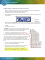
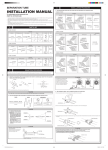
5 Mul ple display configura on for single touch screen When the computer detects more than one display monitors, there are two basic premises for configuring the pla orm to support a certain single touch screen to support mul ‐display:
All the display monitors should be in the same display resolu on.
The first display monitor should be primary or main display. The base point of first display monitor should be (0,0), as pictured below:
We’ll use “touch screen ‘ira100624007’” for this example, and we’ll configure it to be a “1 row, 2 column” mul ‐
display screen like the picture above. (For a 2 row, 1 column array the row/column numbers should be filled in ac‐
cordingly).
Exit the Mul Touch Pla orm. “ira100624007” is a simple screen and, most likely, only one digi zer is installed in the computer so we might need to install another digi zer. Right‐click on “My Computer” and select “Proper es”, then click on “Device Manager”.
Verify the number of “PQLabs Mul Touch Screen” items open in the “Human interface devices” (pictured below). If the number of “PQLabs Mul Touch Screen” items doesn’t match the num‐
ber of monitors you plan to use, then find “PQIntallTouch.exe” in the driver set‐
up directory (usually located in “C:\ProgramFiles\PQLabs\Mul TouchDriver”), and run it once. Then verify, using the “Device Manager”, that the monitor quan ty matches the number of “PQLabs Mul Touch Screen” instances that are ac ve.
Go to the setup directory of Mul TouchPla orm and find the “mtsvrset.xml”, and then open to modify it.
Find the element <mul _display_screen_manager> in the “mtsvrset.xml”. Add the serial number in the <mul _display_screen> elements: <multi_display_screen serial_number="ira100624007"
configure_name="ira100624007"></multi_display_screen>
6 (Con nued)
Find the element <mds_configure>. Edit the text as follows: <mds_configure name="ira100624007" total_row="1" total_col="2"
display_monitor_mode="respective">
<sub_display_screen row_in_matrix="0" col_in_matrix="0">
<calibration point_0_x="" point_0_y=""
point_1_x="" point_1_y=""
point_2_x="" point_2_y=""
point_3_x="" point_3_y="" />
</sub_display_screen>
<sub_display_screen row_in_matrix="0" col_in_matrix="1">
<calibration point_0_x="" point_0_y=""
point_1_x="" point_1_y=""
point_2_x="" point_2_y=""
point_3_x="" point_3_y="" />
</sub_display_screen>
</mds_configure>
Since there are two monitors in this scenario, we needed to create two <sub_display_screen> in the <mds_configure>. Save the “mtsvrset.xml” and start the Mul TouchPla orm, click the “Restore” bu on in the “Calibra on” group. Then you can see the value of calibra on points in last step will be filled in like this: <mds_configure name="ira100624007" total_row="1" total_col="2"
display_monitor_mode="respective">
<sub_display_screen row_in_matrix="0" col_in_matrix="0">
<calibration point_0_x="512" point_0_y="1024" point_1_x="1536" point_1_y="1024"
point_2_x="512" point_2_y="3072" point_3_x="1536" point_3_y="3072" />
</sub_display_screen>
<sub_display_screen row_in_matrix="0" col_in_matrix="1">
<calibration point_0_x="2560" point_0_y="1024" point_1_x="3584" point_1_y="1024"
point_2_x="2560" point_2_y="3072" point_3_x="3584" point_3_y="3072" />
</sub_display_screen>
7 Descrip on of Element Inputs <multi_display_screen>
<multi_display_screen serial_number="" configure_name=""></multi_display_screen>
serial_number It is the serial number of single touch screen which supports mul _display_screen, you need to specify the serial number here.
configure_name The name of “mds_configure”, which specifies how to organize the mul _display_screen. One serial_number can only map with one <mds_configure> <mds_configure>
<mds_configure name="" total_row="" total_col="" display_monitor_mode="">
<sub_display_screen row_in_matrix="" col_in_matrix="">
<calibration point_0_x="" point_0_y=""
point_1_x="" point_1_y=""
point_2_x="" point_2_y=""
point_3_x="" point_3_y="" />
</sub_display_screen>
</mds_configure>
name Indicates the configure name. Generally it’s the serial number of the touch screen or a name defined by the user. The name is the iden ty of each unique <mds_configure> so it should be named differently than any addi onal <mds_configure> that you create.
total_row/total_col indicates the display matrix, for example, ‘total_row=”1” total_col=”2” ‘ indicates two monitors side‐by‐side.
display_monitor_mode The value can be one of {“blent”, “respec ve”}, while the “blent” is default value. blent: all the physical display monitor are connected to PC by a "Mul View Blender"(hardware),and the oper‐
a ng system can only detect one display monitor.
8 respec ve: the opera ng system will detect every monitor individually. sub_display_screen Every <sub_display_screen> belongs to one touch digi zer. Each digi zer will be bound with one display monitor. The posi on of sub_display_screen in the monitor matrix is specified by “row_in_matrix” and “col_in_matrix”(in range of [0,…, total_col]). The “calibra on” in this element stores the calibra on points posi on of the sub_display_screen. There are always four points, and the origin (0,0) is located at the top le corner. Troubleshoo ng
This section provides some diagnostic tests and solutions that you can apply in the event there is a problem with the touch
monitor. If the problem persists or you require additional support, contact Horizon Display support department at
(888) 737-4674 or by emailing [email protected].
Touch monitor does not respond to touches
Make sure the USB cable is connected to the monitor and the computer.
If the problem still persists, try plugging the monitor into a different USB port on the computer.
Touch produces erratic responses on screen
This can occur if the touch monitor has not been calibrated correctly. To fix the problem, recalibrate the touch monitor.
Unable to calibrate the touch monitor
If you have a problem calibrating your touch monitor contact Horizon Display for support.
“Uninstalling and reinstalling the USB device
1.
From the Start menu computer select: Settings/Control Panel/System (in traditional view) and then click on
Hardware tab. You should now enter the Device Manager application.
2.
Right click on [USB Composite Device] and then click on [Properties].
3.
Once on the Properties screen, verify that the location refers to the touch monitor.
4.
Close the Properties screen.
USB not recognized” message appears on screen
This message can appear if the USB port on the computer
does not recognize the monitor. This is often resolved by utilizing a different USB port on the computer.
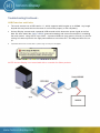
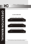
Troubleshoo ng Con nued... USB Extension and Limits
The touch screens use a USB version 1.1, which supports cable lengths up to 15 feet. Any length
beyond this may cause the touch screen to not function properly or fail completely.
Horizon Display recommends a powered USB extender which boosts the power signal as well as
data. We have tested the Gefen USB200 (powered extender) and we were successful in extending
the touch screen using CAT5E up to 300 ft. A powered USB hub (any generic will work) on the Receiving Unit was required for the high powered device to work as well. See diagram below for setup.
If powered devices are not used then a “power surge on hub port” will appear.
NOTE: Horizon Display is not associated with or a reseller for Gefen products.
10 Cleaning Instruc ons
Recommended cleaning solution consists of a 70% or higher isopropyl alcohol in conjunction with a fine micro-fiber cloth.
DO NOT spray/pour alcohol directly to screen; apply to cloth first.
Wipe lightly in one direction. Do not buff aggressively or wipe in a circular motion.
Warranty Informa on Damaged Goods
In the event of damage to this Product or packaging you should immediately advise the shipper and the reseller who sold you
the product. Retain all original packaging. Future shipment of this product in incorrect packaging may void your warranty.
Limited Warranty
1) Horizon Display a division of Horizon Technology, LLC (hereinafter 'Horizon Display'), warrants its products to be free from
defects in material and workmanship during the warranty period and subject to the conditions set forth below. Horizon Display
warrants its products as to form, fit and function, not specific application and to meet the performance and testing parameters
defined in the product's associated customer quotation, purchase order and/or contract between Horizon Display and customer.
If a product proves to be defective in material or workmanship during the warranty period, Horizon Display, at its sole discretion
will repair or replace the product with a similar product provided that a Horizon Display return materials authorization number
(RMA) was issued prior to the return of the product. Replacement parts and or units may include remanufactured or product
refurbished to manufacturers specifications. The replacement unit will be covered by the balance of the time remaining on the
original limited warranty. Warranty period can be found in your original invoice.
2) Horizon Display provides a limited warranty on all custom integrated solutions including; integrated computer products,
integrated storage solutions and integrated display solutions as well as all distributed products including storage and display
products. Warranty terms are for repair at Horizon Display's Integration facility in Lake Forest, CA. Freight expense from the
customer to the repair depot will be the liability of the customer. The freight expense to return the product back to the customer
will be the liability of Horizon Display. The warranty period begins upon the ship date reflected on Horizon Display's invoice. The
balance of the original warranty as detailed in section 1 will cover repairs and or replacements made under the warranty.
3) This warranty is limited to the original purchaser of the product and is not transferable As detailed in section 1, repairs and
replacements will be covered by the balance of the time remaining on the original limited warranty. The original Horizon Display
invoice must accompany all warranty requests. Horizon Display shall be under no liability at all under this warranty if the total
price for the product has not been paid.
4) Warranty period can be found in your original invoice.
5.) Definition of DOA (dead on arrival) - Horizon restricts the DOA period to not exceed 10 days from receipt by customer. This
grace period allows ample time to test product and verify it has been delivered in the condition quoted. If the product fails at any
time within this period, Horizon Display is liable for freight charges to return product and for shipping the replacement/repaired
product. If at any time the product is installed, mounted, or altered, the DOA period ends.
11 How to get Service?
Please contact Horizon Display at (888)737-4674 or email ([email protected]), Monday-Friday 9-5PM (PST) for support.
While on the phone with the technician, every attempt will be made to resolve your issue. If the issue cannot be resolved, the
Horizon Display technician will provide additional instructions as to how to get the unit back to original operation. This may include shipping the unit back to Horizon Display’s Factory Service Center in Lake Forest, CA. If a technician must be dispatched
and the unit fails because of issues related to software, operating system, and/or operator error related the client may be billed
for time and travel expenses. If a product is being retuned to Horizon Display an RMA and instructions will be provided.
Regulatory Compliance Informa on Federal Communication Commission (FCC) Statement
This equipment has been tested and found to comply with the limits for a class A digital device, pursuant to part 15 of the FCC
Rules. These limits are designed to provide reasonable protection against harmful interference when the equipment is operated
in a commercial environment. This equipment generates, uses, and can radiate radio frequency energy and, if not installed and
used in accordance with the instruction manual, may cause harmful interference to radio communications. Operation of this
equipment in a residential area is likely to cause harmful interference in which case the user will be required to correct the
interference at his own expense.
This device complies with Part 15 of the FCC Rules. Operation is subject to the following two conditions: (1) this device may not
cause harmful interference, and (2) this device must accept any interference received, including interference that may cause
undesired operation.
Changes or modifications not expressly approved by the party responsible for compliance could void the user’s authority to
For Customer Support please contact Horizon Display at (888) 737‐4674 [email protected] Or visit us at www.horizondisplay.com/support 12