1
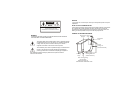
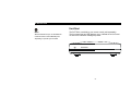
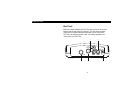
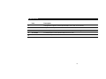
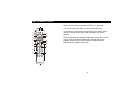
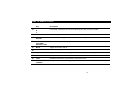
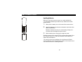
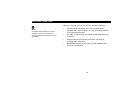
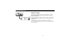
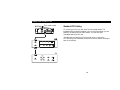
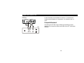
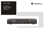
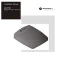
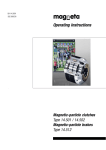
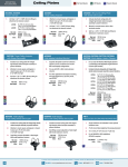
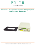
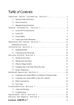
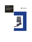
DCT700
User Guide
REPAIRS
CAUTION
RISK OF ELECTRIC SHOCK
If you find the unit in need of repair, contact your cable system operator for repair or
replacement.
NOTE TO CATV SYSTEM INSTALLER
CAUTION: TO REDUCE THE RISK OF ELECTRIC SHOCK,
DO NOT REMOVE COVER (OR BACK).
NO USER-SERVICEABLE PARTS INSIDE.
REFER SERVICING TO QUALIFIED SERVICE PERSONNEL.
This reminder is provided to call the CATV system installer’s attention to Article 82040 of the NEC that provides guidelines for proper grounding and, in particular,
specifies that the cable ground shall be connected to the grounding system of the
building, as close as possible to the point of cable entry as practical.
EXAMPLE OF ANTENNA GROUNDING
WARNING
TO REDUCE THE RISK OF FIRE OR ELECTRIC SHOCK, DO NOT EXPOSE
THIS APPLIANCE TO RAIN OR MOISTURE.
bäÉÅíêáÅ=ëÉêîáÅÉ dêçìåÇ
ÉèìáéãÉåí
Åä~ãé
^åíÉåå~=äÉ~Ç=
áå=ïáêÉ
The lightning flash with arrowhead symbol, within an equilateral triangle,
is intended to alert the user to the presence of uninsulated “dangerous
voltage” within the product’s enclosure that may be of sufficient
magnitude to constitute a risk of electric shock to persons.
^åíÉåå~
ÇáëÅÜ~êÖÉ=ìåáí=
Ekb`=pÉÅíáçå=UNMJOMF
The exclamation point, within an equilateral triangle, is intended to alert
the user to the presence of important operating and maintenance
(servicing) instructions in the literature accompanying the appliance.
This installation should be made by a qualified service person and should
conform to all local codes.
dêçìåÇáåÖ
Åä~ãéë
dêçìåÇáåÖ=ÅçåÇìÅíçêë
Ekb`=pÉÅíáçå=UNMJONF
mçïÉê=ëÉêîáÅÉ=ÖêçìåÇáåÖ
ÉäÉÅíêçÇÉ=ëóëíÉã
Ekb`=^êíáÅäÉ=ORMI=m~êí=eF
kb`Zk^qflk^i=bib`qof`^i=`lab
Important Safety Instructions
1
2
3
4
5
6
Read these instructions.
All the safety and operating instructions
should be read before the appliance is
operated.
7
Keep these instructions.
The safety and operating instructions should
be retained for future reference.
Heed all warnings.
All warnings on the appliance and in the
operating instructions should be adhered to.
Follow all instructions.
All operating and use instructions should be
followed.
Do not use this apparatus near water.
Apparatus shall not be exposed to dripping
or splashing and no objects filled with
liquids, such as vases, shall be placed on
the apparatus.
Clean only with dry cloth.
Unplug this product from the wall outlet
before cleaning. Do not use liquid cleaners
or aerosol cleaners. Use a dry cloth for
cleaning.
8
9
Do not block any ventilation openings.
Install in accordance with the
manufacturer’s instructions.
Slots and openings in the cabinet are provided
for ventilation and to ensure reliable operation
of the equipment and to protect it from
overheating. The openings should never be
blocked by placing the product on a bed, sofa,
rug, or similar surface. Equipment should
never be placed in a built-in installation such
as a bookcase or rack unless proper
ventilation is provided.
Do not install near any heat sources such
as radiators, heat registers, stoves, or
other apparatus (including amplifiers) that
produce heat.
Do not defeat the safety purpose of the
polarized or grounding-type plug.
A polarized plug has two blades with one wider
than the other. A grounding-type plug has two
blades and a third grounding prong. The wide
blade or the third prong are provided for your
safety. If the provided plug does not fit into
your outlet, consult an electrician for
replacement of the obsolete outlet.
10
11
12
Protect the power cord from being walked
on or pinched particularly at plugs,
convenience receptacles, and the point
where they exit from the apparatus.
Power supply cords should be routed so that
they are not likely to be walked on or pinched
by items placed upon or against them.
Use only attachments/accessories
specified by the manufacturer.
Do not use attachments not recommended
as they may cause hazard.
Unplug this apparatus during lightning
storms or when unused for long periods of
time.
This will prevent damage to the video product
due to lightning and power line surges.
13
Refer all servicing to qualified service
personnel.
Servicing is required when the apparatus
has been damaged in any way, such as:
17
~= Power-supply cord or plug is damaged
Ä= Liquid has been spilled or objects have
fallen into the apparatus
Å= The apparatus has been exposed to rain or
moisture
Ç= The apparatus does not operate normally
É= The apparatus has been dropped.
14
15
16
Power lines
An outside antenna system should not be
located in the vicinity of overhead power
lines or where it can fall into such power
lines or circuits. When installing an outside
antenna system, extreme care should be
taken to keep from touching such power
lines or circuits, as contact with them may
be fatal.
Overloading
Do not overload wall outlets and extension
cords as this can result in a risk of fire or
electrical shock.
Object and liquid entry
Never push objects of any kind into this
equipment through openings as they may
touch dangerous voltage points or short-out
parts that could result in a fire or electrical
shock. Never spill liquid of any kind on the
product.
18
Replacement parts
When replacement parts are required be sure
the service technician has used replacement
parts specified by the manufacturer or have
the same characteristics as the original part.
Unauthorized substitutions may result in fire,
electric shock, or other hazards.
Safety check
Upon completion of any service or repairs to
this video product, ask the service technician
to perform safety checks to determine that the
product is in proper operational condition.
19
Battery usage
Notwithstanding any information provided by
Motorola in this manual regarding the use of
batteries, the end user assumes all
responsibility and liability to use and dispose of
batteries in accordance with all applicable
laws, rules and regulations. Motorola will not
be liable to anyone for the end user's failure to
use and/or dispose of batteries in the proper
manner and in accordance with such laws,
rules and regulations, or for any defect
contained in batteries that may cause injury
damage to persons or property.
Regulatory Information
Declaration of Conformity
This device complies with Part 15 of the FCC rules. Operation is subject to the
following two conditions: (1) This device may not cause harmful interference, and (2)
this device must accept any interference received, including interference that may
cause undesired operation.
This equipment has been tested and found to comply with the limits for a Class B
digital device, pursuant to part 15 of the FCC Rules. These limits are designed to
provide reasonable protection against harmful interference in the residential
installation. This equipment generates, uses and can radiate radio frequency energy
and, if not installed and used in accordance with the instructions, may cause harmful
interference to radio communications. However, there is no guarantee that
interference will not occur in a particular installation.
According to 47 CFR, Parts 2 and 15 for Class B Personal Computers and
Peripherals; and/or CPU Boards and Power Supplies used with Class B
Personal Computers, Motorola, Inc., 6450 Sequence Drive, San Diego, CA
92121, 1-800-225-9446, declares under sole responsibility that the product
identifies with 47 CFR Part 2 and 15 of the FCC Rules as a Class B digital
device. Each product marketed is identical to the representative unit tested and
founded to be compliant with the standards. Records maintained continue to
reflect the equipment being produced can be expected to be within the variation
accepted, due to quantity production and testing on a statistical basis as
required by 47 CFR 2.909. Operation is subject to the following condition: This
device must accept any interference received, including interference that may
cause undesired operation. The above named party is responsible for ensuring
that the equipment complies with the standards of 47 CFR, Paragraphs 15.107
to 15.109.
If the equipment does cause harmful interference to radio or television reception,
which can be determined by turning the equipment off and on, the user is
encouraged to try to correct the interference by one of the following measures:
Canadian Compliance
Federal Communications Commission Radio and Television Interface Statement for a
Class ‘B’ Device
•
Increase the separation between the equipment and the affected receiver
•
Connect the equipment on a circuit different from the one the receiver is on
•
Ensure that the cover plate for the security card is secured and tight
Changes or modification not expressly approved by the party responsible for
compliance could void the user’s authority to operate the equipment.
This Class B digital apparatus meets all requirements of the Canadian
Interference-Causing Equipment Regulations. Cet appareil numérique de la
classe B respects toutes les exigences du Règlement sur le matériel brouilleur
du Canada.
DCT700
DCT700
Tested To Comply
With FCC Standards
NOTICE
THEFT OF SERVICE IS A CRIME. INSTALLING THIS DEVICE WITHOUT
PERMISSION OR UNAUTHORIZED TAMPERING, MODIFYING OR
ALTERING IT IN ANY WAY MAY SUBJECT YOU TO CIVIL OR CRIMINAL
PENALTIES. CHECK WITH YOUR LOCAL CABLE COMPANY.
FOR HOME OR OFFICE USE
US Patent - 4476584, 4546387, 4575755, 4621285, 4558464, 4603349, 4613901,
4634808, 4712238, 4792973, 4864615, 4933898, 5083293, 5144664,
5111504, 5406228, 5497112, 5485577, 5091782, 5068724, 5093720,
5376968, 5345408, 5565922, 5517250, 5566089, 4908859, 5396518,
5511096, 5511082, 4631603, 4819098, 4577216, 5363408
This device complies with part 15 of the FCC Rules. Operation is subject to the
following two conditions: (1) This device may not cause harmful
interference, and (2) this device must accept any interference received,
including interference that may cause undesired operation.
Copyright © 2003 Motorola, Inc.
This device incorporates a copyright protection technology that is protected by U.S. patents and other intellectual property rights. Use of the copyright protection technology
is granted by Macrovision for home and other limited pay-per-view uses only, unless otherwise authorized by Macrovision. Reverse engineering or disassembly is prohibited.
All rights reserved. No part of this publication may be reproduced in any form or by any means or used to make any derivative work (such as translation, transformation or
adaptation) without written permission from Motorola, Inc.
Motorola reserves the right to revise this publication and to make changes in content from time to time without obligation on the part of Motorola to provide notification of such
revision or change. Motorola provides this guide without warranty of any kind, either implied or expressed, including but not limited to, the implied warranties of
merchantability and fitness for a particular purpose. Motorola may make improvements or changes in the product(s) described in this manual at any time.
MOTOROLA and the Stylized M Logo are registered in the US Patent & Trademark Office. Manufactured under license from Dolby Laboratories. "Dolby" and the double-D
symbol are registered trademarks of Dolby Laboratories. All other product or service names are the property of their respective owners. MediaCipher is a registered
trademark of Motorola, Inc.
CONTENTS
Introduction ........................................................... 2
Front Panel ....................................................... 3
Rear Panel........................................................ 4
Using the Remote Control.................................... 6
Installing Batteries .......................................... 10
Basic Operation................................................... 11
Turning Power On and Off.............................. 11
Changing Channels ........................................ 11
Electronic Program Guide .............................. 12
Audio/Video Connections...................................13
Connecting your DCT700 ...................................14
Standard TV Cabling.......................................14
Standard VCR Cabling....................................15
Composite Baseband and S-Video.................16
Composite VCR Cabling .................................17
Stereo Cabling Diagram (VCR to Stereo).......18
Stereo Cabling Diagram (TV to Stereo)..........19
Troubleshooting ..................................................20
INTRODUCTION
The DCT700:
•
Supports services such as an EPG, IPPV
and VOD
•
Reclaims bandwidth allocated to analog
channels
•
Combats analog piracy
•
Offers compatibility with MediaCipher
conditional access technology
•
Provides a real-time return path
The DCT700 requires a remote control to operate
(remote control sold separately).
Congratulations on receiving the DCT700 digital consumer terminal,
one of the most advanced interactive digital cable terminals available
today. It’s simple to set up and easy to operate.
The DCT700 can provide an Electronic Program Guide (EPG) menu
that allows you to conveniently select and view programs. You can also
purchase Pay-Per-View special events, recent movies, or Video on
Demand. Video on Demand is similar to renting a video, including the
ability to pause, rewind, and fast-forward.
This guide introduces you to the features and operation of the DCT700.
Access to the DCT700 features is gained through the electronic
program guide.
To get the most out of your DCT700, be sure to read your
electronic program guide instruction manual and remote control
User Guide.
2
INTRODUCTION
Front Panel
NOTE
We recommend that you use the Motorola
universal remote control DRC450 (sold
separately) to operate your DCT700.
The DCT700 is controlled by your remote control (sold separately).
The front panel has two LED displays: one to indicate the unit is turned
on and one to indicate a message is present.
ON
MESSAGES
3
INTRODUCTION
Rear Panel
Before you begin installing the DCT700, take a moment to become
familiar with the rear panel connections. The rear panel includes
connectors for system cabling and a power cord to connect the
DCT700 to an electrical power outlet. For cabling diagrams, see
“Connecting Your DCT700”.
1
2
TO
TV/VCR L
+
+
+12V
DC
R
AUDIO
RF IN
3
4
4
VIDEO
5
INTRODUCTION
Item
Description
1
AUDIO OUT
Left/right audio outputs to connect the DCT700 to a TV, VCR, or A/V receiver.
2
VIDEO
Composite video output to connect the DCT700 to a TV, VCR, or A/V receiver.
3
RF IN
A coaxial input that is connected to the cable wall outlet, see Connecting the DCT700.
4
TO TV/VCR
A coaxial output to connect the DCT700 to the TV or VCR.
5
Power
This is the DC power connection.
5
USING THE REMOTE CONTROL
1
Use the remote control to operate the DCT700, TV, and VCR.
Your remote control may differ from the one illustrated here.
AU DIO
2
3
4
5
6
7
8
VCR/D VD CA BLE
HELP
PAGE
11
12
LOCK
PAGE
INFO
EXIT
14
15
16
OK
M ENU
VOLUME
9
10
TV
PO WER
LAST
CH ANNEL
FAVOR ITE
THEM E
LIST
CA NCEL
A
B
C
1
2
3
4
5
6
7
8
TV/VCR
REW
PAUSE
RECORD
19
The table following this drawing describes the functions of the remote
control. Some of the features described in the table may not be
available. Check with your service provider to determine which
features are being offered in your area.
20
9
ENTER
0
DAY
STOP
17
18
For information on operating and programming your remote control,
refer to the remote control User Guide supplied by your service
provider.
DAY
PLAY
21
F.FWD
13
6
USING THE REMOTE CONTROL
Key
Description
1
AUDIO, VCR/DVD,
CABLE, OR TV
Selects a device to control. The selected mode will remain active until you press another key.
2
HELP
Displays the help screen.
3
POWER
Turns the currently selected device on or off.
4
PAGE ▲ PAGE ▼
Pages through menu screens and the program guide.
5
EXIT
Exits a menu or program guide.
6
◄ ▲ ► ▼ CURSOR
Moves the cursor around the program guide and menu screens.
7
OK
Selects menu options, Pay-Per-View events or programs from the program guide.
8
GUIDE
Displays the program guide.
9
VOLUME +
VOLUME -
Increases or decreases the volume of the VCR, TV, or audio device. The device must be selected
before you can increase or decrease the volume.
7
USING THE REMOTE CONTROL
Key
Description
10
A
B
C
Functionality is determined from services offered by your cable TV service provider.
11
NUMBER KEYS
Use to directly select a channel.
12
TV/VCR or
BYPASS
When in VCR mode, toggles between television and VCR. Bypass is not available.
13
STOP, PAUSE,
PLAY, REW,
RECORD, F.FWD
Controls the VCR/DVD or CD player.
14
MUTE
Toggles the sound on and off.
15
LOCK
Use to limit viewing of selected programs or to view the Pay-Per-View menu.
16
INFO
Displays the current channel and program information (not supported by all applications).
17
MENU
Displays the main menu.
18
LAST
Recalls the last channel or goes back one screen in the menu.
19
CHANNEL +
CHANNEL -
Changes the channels by moving up or down.
8
USING THE REMOTE CONTROL
Key
Description
20
FAVORITE
Displays preset favorite cable channels.
21
ENTER/MUSIC
Displays digital music channel menus. On some TV models press to enter channels.
9
USING THE REMOTE CONTROL
Installing Batteries
Before you can use the remote control, you must install two AA
(1.5-volt) alkaline batteries (provided with your Motorola universal
remote control):
1
2
+
Slide open the battery door on the back of the remote control.
Insert the batteries in the direction indicated on the inside of the
battery compartment.
Batteries installed incorrectly can cause battery leakage and
corrosion that will damage the remote control.
+
3
Slide the battery door closed until it snaps into place.
Point the remote control at the DCT700, and then press POWER. If the
DCT700 does not turn on, check the orientation of the batteries or
replace with new batteries.
Your remote control may be different from the Motorola DRC450
Universal Remote Control illustrated here. Refer to the remote control
User Guide for details on installing batteries.
10
BASIC OPERATION
Turning Power On and Off
NOTE
The DCT700 requires a remote control to
operate.
To turn the DCT700 on or off, be sure it is in cable mode by pressing
CABLE on your remote control and then press POWER.
Changing Channels
Be sure the remote control is in cable mode and enter the number of
the channel you want to tune using the numeric keys, or press
CHANNEL + or – on the remote control to step through the channel
selection.
11
BASIC OPERATION
Electronic Program Guide
The electronic program guide displays information about TV programs
and enables you to access features such as Parental Control or
Pay-Per-View. Electronic program guides vary with each service
provider. Reference the electronic program guide instruction manual
for detailed instructions.
12
AUDIO/VIDEO CONNECTIONS
Before you begin to hook up your DCT700, review the following:
NOTE
It is important to remember not to place
anything on top of the DCT700 and to
provide for adequate ventilation to prevent
overheating.
•
For basic cable connections, use 75-ohm coaxial cables
equipped with F-type connectors. You can find coaxial cables in
your local electronics store.
•
For audio or video outputs, use cables equipped with RCA-type
connectors.
•
Disconnect power from the DCT700 before connecting or
changing cable connections.
•
Do not place anything on top of the DCT700, especially other
home video components.
13
CONNECTING YOUR DCT700
From cable outlet
DCT700
TO
TV/VC R L
+
+
Standard TV Cabling
+12V
DC
R
RF IN
AUDIO
VIDEO
TV
AUDIO
IN
i
CABLE IN
AUDIO
OUT
o
VIDEO IN
S-VIDEO IN
VIDEO OUT
S-VIDEO OUT
Use 75-ohm coaxial cables to connect your DCT700 to a TV. This is
the most common cable connection, and it provides all of the basic
features of the DCT700.
If you are connecting the coaxial TO TV/VCR connector on the DCT700
to the coaxial CABLE IN connector on the TV, you must tune your TV to
channel 3 or 4.
The illustrated connections will not provide stereo. Connect the
DCT700 using RCA baseband connectors to receive stereo (illustrated
later in this section).
14
CONNECTING YOUR DCT700
From cable outlet
DCT700
TO
TV/VCR
+
+
To connect your VCR, you will need 75-ohm coaxial cables. The
illustrated VCR connection enables you to record the program you are
watching, including Pay-Per-View events. You can also view
videotapes just as you do now.
+12V
DC
R
AUDIO
RF IN
CABLE IN
CABLE OUT
AUDIO
IN
Standard VCR Cabling
VIDEO
The illustrated connections will not provide stereo. Connect the
DCT700 using RCA baseband connectors to receive stereo (illustrated
later in this section).
L
AUDIO
OUT
R
L
VIDEO
IN
R
S-VIDEO
IN
VIDEO
OUT
S-VIDEO
OUT
TV
AUDIO
IN
i
CABLE IN
AUDIO
OUT
o
VIDEO IN
S-VIDEO IN
VIDEO OUT
S-VIDEO OUT
15
CONNECTING YOUR DCT700
DCT700
TO
TV/VCR
L
+
+
In these illustrations the baseband connectors on entertainment
components are labeled R for right audio, L for left audio, and V or
VIDEO.
+12V
DC
R
AUDIO
RF IN
VIDEO
Composite Baseband
TV
Connecting the DCT700 using the RCA-type baseband outputs
®
enables you to experience stereo and Dolby Surround sound when
available.
AUDIO
IN
i
CABLE
IN
AUDIO
OUT
o
VIDEO IN
S-VIDEO IN
VIDEO OUT
S-VIDEO OUT
16
CONNECTING YOUR DCT700
DCT700
Composite VCR Cabling
TO
TV/VCR
+
+
+12V
DC
This diagram illustrates how to connect the DCT700 to a VCR using
the audio connectors on the VCR.
R
RF IN
CABLE IN
CABLE OUT
AUDIO
AUDIO
IN
L
AUDIO
OUT
VIDEO
R
L
VIDEO
IN
R
S-VIDEO
IN
VIDEO
OUT
S-VIDEO
OUT
TV
AUDIO
IN
i
CABLE IN
AUDIO
OUT
o
VIDEO IN
S-VIDEO IN
VIDEO OUT
S-VIDEO OUT
17
CONNECTING YOUR DCT700
Stereo Cabling Diagram (VCR to Stereo)
DCT700
TO
TV/VC R L
+
+
This diagram illustrates how to connect the DCT700 to a stereo using
the audio connectors on the VCR. The VCR sound is played through
the stereo.
+12V
DC
R
AU DIO
RF IN
CABLE IN
CABLE OUT
AUDIO
IN
L
AUDIO
OUT
VIDEO
R
L
VIDEO
IN
R
S-VIDEO
IN
VIDEO
OUT
S-VIDEO
OUT
TV
AUDIO
IN
o
CABLE IN
AUDIO
OUT
i
VIDEO IN
S-VIDEO IN
VIDEO OUT
S-VIDEO OUT
STEREO
AUDIO
IN
i
AUDIO
OUT
o
18
CONNECTING YOUR DCT700
Stereo Cabling Diagram (TV to Stereo)
DCT700
TO
TV/VCR
+
+
This configuration provides for the TV sound to play through the
stereo.
+12V
DC
R
AU DIO
RF IN
CABLE IN
CABLE OUT
AUDIO
IN
L
AUDIO
OUT
VIDEO
R
L
VIDEO
IN
R
S-VIDEO
IN
VIDEO
OUT
S-VIDEO
OUT
TV
AUDIO
IN
i
CABLE IN
AUDIO
OUT
o
VIDEO IN
S-VIDEO IN
VIDEO OUT
S-VIDEO OUT
STEREO
AUDIO
IN
i
AUDIO
OUT
o
19
TROUBLESHOOTING
Before calling your service provider, review the troubleshooting guide. This information is to help you quickly solve a
problem. If your problem still exists, contact your service provider.
Problem
Possible Solution
No sound
Press MUTE on the remote control to restore the volume level.
Check that the stereo is set to the proper input source.
Turn on your VCR.
Make sure the TV or stereo volume is set to an appropriate level.
No picture
Check to be sure that all cables are connected properly (hand-tighten if
necessary).
If connected through the baseband RCA video connection, make sure the cables
are connected properly.
If you are watching TV using your VCR, be sure your VCR is powered and
running.
Picture or sound is noisy on one channel
Reconnect the cable and hand-tighten if loose.
Sound from only one stereo speaker
Hand-tighten or reconnect the cables properly. Be sure wires are not frayed and
plugs are not bent or broken.
20
TROUBLESHOOTING
Problem
Possible Solution
No power
Reconnect the power cord. Be sure the DCT700 is plugged into an outlet that is
always live.
Remote control does not work
Press CABLE on the remote control to ensure the remote control is in cable mode.
Change the batteries in your remote control according to the instructions in the
section, “Installing Batteries.”
Be sure that nothing is on the DCT700 or blocking a clear line of sight between it
and the remote control.
21
512555-001
12/03
English
MGBI