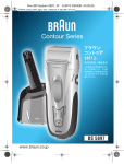
1
Portable Air Conditioner with
Heat Pump Technology
PH4-13R-01
Operating Instructions
3092402
®
© 2008 Soleus Air International
Thank you for choosing a Soleus Air Portable Air Conditioner with Heat Pump Technology. This
owner's manual will provide you with va luable information necessary for the proper care and
maintenance of your new product. Please take a few moments to thoroughly read the instructions and
familiarize yourself with all the operational aspects of your new Soleus Air Portable Air Conditioner
with Heat Pump technology.
For your own records, please attach a copy ofy~)Ur sales receipt to this manual. Also, write the store
name/location, date purchased, and serial number below:
Store Name: _ _ _ _ __ _ _ _ __ _ _ _ _ _ _ _ __ _ _ _ _
Location: _ __ _ _ _ _ _ __ _ _ _ _ _ _ _ __ _ __ _
Date Purchased: _ _ _ _ _ _ _ _ __ _ _ _ _ _ _ _ __ _ __
Seria l N umber (located on back of unit): _ _ _ _ _ _ _ _ __ _ _ __
IMPORTANT INSTRUCTIONS
Before installing and using your portable air conditioner, please read this owner' s manual carefully. Store this
manual in a safe place for future reference.
I) Always place the unit on a level surface.
2) Never use or store gasoline or other flammable vapor or liquid near this unit unless instructed by this
manual.
3) Maintain at least 10 inches (25 cm) clearance space around this unit. Do not block or cover air inlet or
outlet grilles.
4) The unit must be connected to a correctly grounded power supply.
5) Do not start or stop the unit by inserting or pulling out the power plug.
6) Do not use an adapter plug or extension cord.
7) Do not use the unit in the immediate surroundings ofa bath, a shower or a swimming pool.
8) Do not insert anything into the air outlet. Do not obstruct air inlet or outlet grills unless instructed by this
manua1.
9) Do not It:t I;hi ldrcn play ncar this unit.
10) Always inspect the cord for signs of damage bcfore use. If the power cord is damaged, it must be replaced
by the manuracturer or a qualified service technician.
11 ) When cleaning the unit, always tum the unit ofT and unplug the power cord.
12) When the unit is not in use. always remove thc vcnting kit from window.
2
PACKAGE CONTENTS
Portable Air Conditioner
Exhaust Hoses (2)
Hose Adapters (2)
Wi ndow Kit Adapter (2)
Air Intake and Outlet Covers (2)
Remote Control
AAA Batteri es (2)
Window Kit· 4 Sl iding Panels ( I dua l hose panel, I single hose panel , 2 extension panels)
Air Intake Vent for Single Hose Insta llation (Add itional Accessory) (\)
Owner' s Manual
SPECIFICATIONS
•
The cooling capac ity is measured at an ambient temperature of DB 86 of, \VB 78 of.
•
Noise level is measured at a distance of 3.28 ft away from the front of the unit, when Ihe unit is in cooling mode.
•
Power consumption is measured when the fan runs at the highest speed setting.
•
These specifications are for reference only. For actual data, please refer to the rating label on the back oflhe unit.
•
[Cthe environment temperat ure is higher than the max operating temperature or lower than the minimum operating temperature,
the air conditioner may not wo rk properly.
MODEL
PH4-13R-Ol
COO LIN G CAPAC ITY
13,000 BTUIH
HEATI NG CAPAC ITY
12,500 BTUI H
DEHUMIDIFIER CAPACITY
60 plsJDay
COOLING
HEATING
AIR FLOW VOLUME
POWER
POWER SOURCE
1390W
llBOW
225 CFM
115 V- 60 HZ
11 AND 1 12.5 AMP
HEATING 1 COOLING
SO UND PRESSURE LEVEL
50 dB(A) at Ihe lowest fan speed
NET WEIG HT
BB Lbs
OPERATI NG
TEMP
COOLI NG
60.B1' -107 .61'
HEATING
231' -89.61'
UNIT
19" W X32.25" H x 18.5" D
PACKAGE
22 .6" W X34 .3" H x 21 .4" D
DIME NS IONS
REFRIGERANT
R22
3
LCDI POWER CORD AND PLUG
This air conditioner is eq uipped with an LCD I (Leakage Current Detection and Interruption) power cord and
plug as required by US National Electric Code 440.65. This cord consists of a length of shielded flexible cord
with no termination on the load side and a LCDI attachment plug on the line side.
The LCD I power cord and plug will remove the supply source via electrical disconnect (circuit trip) if the
nominal current leakage between the cord shield and e ith er load conductor exceeds a predetermined va lue.
The cord will remain de-energized until the devise has been manually reset. This is intended to reduce the ri sk
of a fire in the power cord or combustible materials nearby. The cord shields arc not grounded and they must
be considered a shock hazards if exposed. The cord shie ld must not be connected to ground or to any exposed
metal.
The test and reset buttons on the LCDI Plug are used to check if the plug is functioning properly. To tesl:
1. Plug power cord into wall o utlet
2. Press TEST Button, circuit should trip, cutting powcr to the air conditioner
3. Press RESET button for use
If test button is pressed and unit can st ill be turned on, current leakage has been detected. Do not use the air
conditioner or attempt to reset the LCDI Plug. Contact Soleus Air Customer Scrvice for troubleshooting
recommendations.
I
RESET
TEST
,
,-
/
WARNING:
I. DO NOT press the TEST button while the air conditioner is operating.
2. The TEST and RESET buttons should not be used as "ON" and "OFF" switches .
3. The cord and plug are not intended to offer protection to externally connected loads o r supp ly circuits.
4. The cord and plug are intended for indoor use on ly.
4
PARTS & ASSEMBLY
PARTS
EXHAUST HOSES
~,\Ml)LHose
E)(haust Hose
1?;~L..~:)~:"'-__ Window Kit
Adaptor
WINDOW KIT
,
ASSEMBLY & INSTALLATION
INSTALLATION
When the unit is operating as an air conditioner, heater, or dehumidifier, the unit draws in fresh outdoor air and exhausts
hot air (in AC or dehumidifier mode) or cool air (in Heat mode) out orthe room to complete the air exchange. When the
unit is operating in fan mode, no outdoor air exchange takes place. The window kit and exhaust hose do not need to be
installed when the un it is used as a fan.
NOT E: T he supplied w indow kit can be insta lled in sliding w indows a nd sliding glass doors up to 8 ft. lon g
(approx im ate length).
MOUNTING THE EXHAUST HOSES
•
Choose a suitable location, near a grounded electrical outlct and su itable window or door. Remove
packaging and locate components.
•
•
Extend both ends of the exhaust hoses approximately 6 inches.
Screw the window kit adapter onto one end of the exhaust hose clockwise. Screw Ihe hose adapter onlo
•
Remove outlet covers from the back of the unit by screwing them counter-clockwise, then lifting up.
•
Mount the exhaust hoses onto the back of the unit by lock ing the hose adapters into place.
the o ther end of the exhaust hose clockwise. Repeat o n the o lher exhaus t hosc.
5
DUAL HOSE WINDOW KIT INSTALLATION - To quickly and efficientty cool a large area .
NOTE: The air conditioner in the images below may differ from the air conditioner you purchased. These
images are for your reference and show how to connect any Soleus Air dual hose air conditioner.
Installation of the Venting Kit
Innov.uv. prodloICtI for. dMner,
men comfol'table world.
FOR DUAL HOSE PORTABLE AIR CONDITIONERS
The venting kit must be Inst.lled In order lor thfI unit to
work correctly in the air conditioning, heating 01'
dehumidifying mode. The venting kit does not need to be
used while the unit is fennlng.
m
The window kit has been designed to into most vert/cIII
and horizontal window openings. The window lUI CIJIJ also
be used in a sliding door.
1. Choose a S4.1itable location, neer a gtOl.lnded e\ec:tricaI
outlet and e S4.1iteble window or do<w. Remove
packaging and locate components. (figure a)
2. Remove the outlet covers from the bad!. of the unit by
screwing them counter-clockwi ... then lifting up.
(fIgure b)
3. Pull out one end of the exhaust hose, then SCIeW on
the adapter clockwise. Repeat on other exhaust hose..
(figure c)
4. Pull out the opposite end of the exhaust hose. u.n
screw on the window kit adapter clockwise. Repeat on
other exhaust hose. (figure d)
5. Mount the exhaust ho... onto the back of the unil
(figure e)
6. Open the window or door and adjust the length of the
window kit to fit the opening. (figure f) It necessary.
mark the kit and cut down one end to properly fit the
opening. (figures g & h)
7. Attech the window kit adapters to the window kit.
(figure i) Close the window Ot door tighUy. (figure j)
Vour Portable Air CondlUonar ia now,..cty to cooIl
NOTE: When using the vendngsyatem, keep thfI uhausr
hose 8S shott and straight 8S possible. The exhaust hose
can be shortened, but it is not recommended to inaeue
the length of the exhaust hose. Do not use an exten4lon
COI'd with your porl,able air conditioner.
When using to a sliding door, It Is recommend to milt.
the air outlet up to air Inlet
6
SINGLE HOSE EXHAUST & WINDOW KIT INSTALLATION
When you want quick spot cooling, install the PH4- 13R-O I using the single hose window kit installation.
For Single Hose Installation
Install on ly the left exhaust hose over the circular air out let (th is out lct will be on the left side of the unit when
you are facing the back of the unit). Cover the right circular air intake using the exhaust intake cover. After
installing the hose remove the square air intake cover on the back of the unit and in sta ll the square air intake
vent with removable/washab le filter.
EXhaustHoselnSUU~",::.~d
____~~~~~;-"~====:m=E=!r""""
onto circular air 0
on left side
Exhaust cover Installed
over circular air intake on
+----=-'7--- right side
i~iEgg
..........
........
Air Intake Vent-
Air Intake Cover
"Additional Accessory
For Single Hose Window Kit Installation
To install the window kit, follow the same directions on page 6 for dual hose installation, but instead of using
the dual hose window kit panel, use the single hose panel pictured below.
Single Hose Window Kit Panel
8
CONTROL PANEL, DISPLAY, & OPERATING INSTRUCTIONS
CONTROL PANEL & MULTI·COLOR DISPLAY
FAN SPEED SUnON
CONTROL PANEL
SWING BUnON
POWER BunON
TIMER BUTTONS
MODE BunON
TEMP SELECT
MUL TI·COLOR DISPLA Y
AUTO
AIC
D HUM.
FAN
HEAT
O........
FANSPEED
TEMPERATURE
AND TIMER
.u:."":'::'--il-I- INDICATOR
OSCILLATION ON/OFF
SLEEP MODE
ON/OFF
BUCKET FULL
TIMER ON
TIMER OFF
COMPRESSOR ONIOFF
,
I
9
OPERATING INSTRUCTIONS
CONTROL PANEL BUTTONS (Refer to the images on page 9)
1) Power On and Off - Press the POWER button once to manually turn the unit on . Press the POWER
hutton once morc to turn the unit off.
2) Mode Selection - Press the MODE Button repeated ly to cycle between the different modes: Auto mode,
Air Conditioner, Dehumidifier, Fan only, and Heater.
3) Fan Speed Control - Press the FAN SPEED Button to cycle through the different fan speeds: High,
Medium, and low . The fan speed can be visuall y distinguished by the speed of the fan icon on the front
panel. There is an additional auto speed setting that is enabled in only heatin g and cool ing modes. This
speed is next setting after low when pressing th e speed control button. The speeds will cycle through in thi s
order: Low, Medium , High , Auto. Each change in speed will be associated with a "beep" sound from the
unit.
4) Temperature - Se lect the des ired temperature by pressing either T or .. key when using the unit in
cooling or heating mode. T he temperature indicator flashes to display the desircd temperature setting. A ficr
the te mperature is set, the unit wi ll display this temperature setting until it is changed by the user. The
Multi-color display shows temperature in Cels ius or Fahrenheit. Pressing the " and ... buttons sim ultaneously wi ll change the temperature select between OF and °c.
5) Timer - To program the timer, press the TIMER ON button until the di spl ay shows a flashing " (9-+1 "
Press the .. or T button s to change the clock to the desired time for the unit to automatically turn on.
Press the TIMER OFF button and the display on the un it will flash " C9 -+ 0 ". Press the .. or T
buttons to change the clock to the desired time for the unit to automatically tu rn off. The TIMER OFF
ind icator will flash for 3 seconds to activate the times you programmed.
NOTE: The timer will also remember your settings when it is set. If you set the tim er while in A ir Conditi oning mode, the timer will automatically turn the unit on and off in air conditi oning mode according to the des ired programmed times. The timer will also remember the temperature sett ings, fan speed, and osci llation setting . The timer works when the unit is in Air Conditi oner mode, Heating mode, Dehumidifier mode, Fan
mode, and Auto mode
OPERATING THE UNIT USING THE CONTROL PANEL
Air Conditioner Mode
I) Install the exhaust hoses and window kit properly (see pages 6, 7 & 8).
2) Plug the Power Cord into an electrical outlet.
3) Turn on the unit by pressing the POWER button on the control panel.
4) Press the Mode button until the"
*
" icon appears on the Multi-color display
5) Press the .. or T buttons until the desired room temperature appears on the control panel
display. The temperature ranges from 61 °F _ 88 OF (16 "c _3 1 "C).
6) Select the desired fan speed by pressing the FAN SPEED button.
10
NOTE: During hot days, the unit wil l cool the room most efficiently by setting the temperature at the lowest
setting and the fan speed on high. Reducing the length of the exhaust duct, insulating the exhaust hose and
window kit, and keeping direct sunlight to a minimum will also improve the cooling efficiency.
NOTE: When the unit is running on cooling mode, the exhaust hoses are required and must be
vented outside using the supplied window kit.
Dehumidifier Mode
I) Install the exhaust hoses and window kit properly (see pages 6, 7 & 8).
2) Plug the Power Cord into an electrical outlet.
3) Turn on the unit by pressing the POWER Button on the control panel.
4) Press the MODE button until the"
0 " appears on the control panel display.
NOTE: The unit operates at low fa~ speed during dehumidifier mode. The unit cools room slightly during
the dehumidification. Keep the windows and doors closed to aid the effectiveness ofthe unit in removing the
moisture from the room.
NOTE: When the unit is running on dehumidifier mode, the exhaust hoses are required and must
be vented outside using the supplied window kit.
NOTE: The unit will not perform in dehumidifier mode when the room temperature is lower than 61 °F.
Fan Mode
I) Plug the Power Cord into an electrical outlet.
2) Turn on the unit by pressing the POWER button on the control pane l.
2f5 "
3) Press the MODE button until the"
icon appears on the control panel display.
4) Select the fan speed by pressing the FAN SPEED button.
5) To circulate more air, press the SWING button on the remote control. The louvers will oscillate in our
exclusive WAVEFLO® pattern which moves the louvers up and down to increase air circulation.
NOTE: It is not necessary for the exhaust hoses and window kit to be installed to operate the unit in fan mode.
Heating Mode
I) Install the exhaust hoses and window kit properly (see pages 6, 7 & 8).
2) Plug the Power Cord into an electrical outlet.
3) Turn on the unit by pressing the POWER button on the control panel.
~ "icon
appears on the control panel display.
4) Press the MODE button until the"
S) Press the'" or ... buttons until the desired room temperature appears on the control panel display. The
o
temperature ranges from 61 F - 88 F (16 C - 31 C).
6) Select the fan speed by pressing the FAN SPEED button. It is recommended to set the fan speed to low.
0
0
0
NOTE : When heal mode is selected, the unit will shut down for 3-5 minuWs,
th~n
start in healing mode.
NOTE: When the unit is running on heating mode, the exhaust hoses are required and must be
vented outside using the supplied window kit.
"
Auto Mode
I) Install the exhaust hoses and window kit properly (see pages 6, 7 & 8).
2) Plug the Power Cord into an electrical outlet.
3) Turn on the unit by pressing the POWER button on the control panel.
<-
4) Press the MODE button until the" \!
by pressing the FAN SPEED button.
" icon appears on the control panel display. Select the fan speed
NOTE: During AUTO mode, the unit operates in Heating mode when the room temperature is below 68 of,
Dehumidifier mode when the room temperature is between 68 of to 80 of. And Air Conditioner mode when
the room temperature is above 80 of.
Sleep Mode (This mode can only be selected when using the Remote control)
I) To set Sleep mode, make sure the unit is in Air Conditioner mode or Heating mode.
2) Press the SLEEP Button on the remote control. The " :) " icon appears on the control panel display.
3) When in SLEEP mode, the fan will run on low to keep fan noise at a minimum.
4) When in Air Conditioner mode, the temperature setting will gradually increase to 2 of above the original set
temperature for 6 hours. After 6 hours the temperature setting wi ll return to, the set temperature.
5) When in Heating mode, the temperature setting wi ll gradually decrease to 2 F below the original set temperature for 6 hours. After 6 hours, the temperature setting will return to the set temperature.
6) When in Dehumidifier mode, the temperature will not change when Sleep mode is selected.
Compressor Indicator
The" OQ " icon will light up on the control panel display when the compressor turns on . The ;,
turn off when the compressor shuts off.
cD " icon will
12
Emergency Condensate Holding Tank
When the room temperature is low and the indoor humidity is high, the air cond itioner may not be able to
evaporate some of the moisture fast enough. When this happens, the water will accumulate in an emergency
condensate tank inside the unit. Once the emergency condensate tank is full, the unit will automatically shut
off and the" t;j " will appear on the control panel display . To empty the condensate tank, unscrew the screw
plug at the bottom back of the unit. You will need a small pan, approximately I" high to catch the water coming out of the condensate tank. Once the condensate tank is drained, the unit will begin work ing within a few
minutes . The emergency condensate tank holds approximately 1.5 Liters of water. Another option is to purchase a sma ll hose from a hardware store that can fit around the 5/8" drain plug on the back of the unit and
drain the unit into a gravity drain or larger pan for continuous drainage.
To resume operation quickly, empty the water container according to the fo ll owing steps:
I. Turn the unit ofT. Do not move the unit when the water container is full.
2. Place the drain pan accessory under the drainage port at the back of the unit.
3. Remove the screw plug from the drain hole. The condensate water will drain out automatically. When the
drain pan is full, screw the screw plug back onto the drainage hole to stop the water flow. Empty the drain
pan. Repeat until all the water is emptied.
Once the water container has been emptied, screw the plug back onto the drain hole. Do not allow the
water to drip continuously into the drain pan, as it might easily overflow.
SCREW PLUG
DRAIN HOLE
13
OPERATING THE UNIT USING THE REMOTE CONTROL
REM OTE CON TROL
- -t- LCD DISPLAY
MODE BUTTON
POWER BUnON
FAN SPEED _ _ _~
"-r~
SWING (LOUVER _ _ __
OSCILLATION)
"t-=i j b==-
TEMP SETTING
...::,_.:
::::----;1---
TIMER ON
SLEEP BUTTON
HOUR $ELECTER
"
'.,N'UTE SELECTER
14
REMOTE CONTROL OPERATING INSTRUCTIONS
I) Power On and Off -If the unit is already on, press the POWER (I/O) button on the remote while pointing the remote away from the unit. This will turn the remote on. If the unit is off, now press the POWER
(1/0) button once to manually turn the unit on. Press the Power button once more to turn the unit off.
When you press the POWER button the upper right square on the remote control LCD Display will light
up. When in Air Conditioner, Heating, and Auto mode, the selected temperature will appear on the remote
control display. When the unit is in Fan mode and Dehumidifier mode you will see the " ••" icon instead of
the set temperature. This shows that temperature selection is not available when the unit is in Fan or Dehumidifier mode.
2) Mode Selection - Press the MODE Button repeated ly to cycle between the different modes: Auto, Air
Conditioner, Dehumidifier, Fan on ly, and Heater mode. The upper left square on the Remote control display will light up showing which mode is selected. In Air Conditioner mode the display wi ll show
"COOL", in Heating mode the display will show " HEAT", in Dehumidifier mode the disp lay will show
" DRY", in Fan mode the display wi ll show "FAN", and in Auto mode the display will show "AUTO".
3) Fan Speed - Press the FAN speed button to cycle through low, medium, and high fan speeds. The display on the remote control will show LOW, MED, & HIGH under the "SPEED" label on the remote control LCD display. There is an additional auto speed setti ng that is enabled in only heating and cooling
modes. This speed is next setting after low when pressing the FAN speed button on the remote control.
The speeds will cycle through in this order: High, Medium. Low, Auto. Each change in speed will be associated with a "beep" sound from the unit. The remote control will not display "AUTO" under the speed
label. Once Auto fan speed is selected the unit will beep and there will not be a fan speed displayed on the
remote control.
4) Temperature Setting - When the unit is in Air Condit ioner or Heating mode you can select your desired
temperature. Press the.&. or ... to select your desired temperature setting. The temperature on the LCD display on the remote control will increase or decrease accordingly. Pressing the'" and'" buttons simu ltaneously will change the temperature select between OF and
0c.
5) SLEEP MODE - See "SLEEP MODE" on page 12.
6) SWING - To turn on the exclusive WA VEFLO® oscillat ion, press the SWING button on the remote
contro\. Once you press SWING. the louvers on the unit will osc illate up and down. The bottom left
"icon when WAVEFLO® oscillation (SWING) is
square of the remote control display will show the"
selected.
...............
7) TIMER - To program the timer, first press the T-ON button. Once T-ON is pressed the auto-on timer will
blink in the bottom right rectangle of the remote control display. Press the MIN and HOUR buttons to
change the clock to the desired time for the unit to automatically turn on. The minutes will increase by 10
with each press of the MIN button and the hours will increase by I with each press of the HOUR button.
Press the T-OFF button and the remote control display will flash the desired auto-off timer. Press the MIN
and HOUR buttons to change the clock to the desired time for the unit to automatically turn off. The timer
is set when the auto-ofT time stops flashing and the words "ON" and "OFF" are displayed next to the time.
8) CLOCK - To set the clock on the remote control, hold down either the MIN or HOUR button until the
displayed time flashes on the remote control display. Change the minutes by pressing the MIN button and
change the hours by pressing the HOUR button.
15
MAINTENANCE
Note: Make sure power is off and the power cord is not plugged into an electrical outlet prior to
performing any maintenance on the unit.
Clean or replace filter - If the air filter is blocked with a dust, the airflow volume may reduce. It is
recommended to clean the filter once every two weeks or as needed.
1) Remove the filter from the filter com partment on the back of the unit.
2) Wash the air filter by immersing it gently into warm water w ith a neutral detergent. Rinse the filter
and dry it thoroughly out of sunlight.
3) Slide the filter back into the filter compartment after it is thoroughly dried.
4) If the filter is torn or unusable, order a new filt er by call ing the customer serv ice number on the
warranty page of this manual.
Clean the unit Ho using
I) Keep the unit from being exposed directly to the sun to prevent co lor fading.
2) C lean the surface with a damp cloth and dry it with a soft towel.
Storing the Unit for an Extended Period of Time or Transporting the uni t
I) Empty any excess water by unplugging the water drainage stop in thc back of the unit (located at
the bottom).
2) Unplug the unit.
3) The unit should be stored in a cool dry place.
DISCLAIMER
ALL INFORMATION AND THE TECHNICAL SPECIFICATIONS PRESENTED IN THIS USER'S MANUAL ARE THE
PRESENTATION OF THE MANUFACTURER. SOLEUS INTERNATIONAL HAS NOT CONDUCTED INDEPENDENT
TEST TO THE INFORMATION AND THE SPECIFICATIONS PRESENTED HEREWITHIN.
16
WARRANTY
One Year Limited Warranty
Soleus International Inc. warrants the accompanying Soleus Air PH4-1 3 R Portable Air Conditioner with Heat Pump
technology to be free of defects in material and workmanship for the applications specified in its operation instruction
for a period of ON E (I) year from the date of original retail purchase in the United States.
If the unit exh ibits a defect in normal use, Soleus International Inc. will, at its option, e ither repair or replace it, free of
charge within a reasonable time after the unit is returned during the warranty period.
As a condition to any warra nty service obligation, the consumer must present this Warranty Certificate along with a
copy of the original purchase invoice.
TillS WARRANTY DOES NOT COVER:
•
•
•
•
•
Damage, accidental or otherwise, to the unit while in the possession of a consumer not caused by a defect in
material or workmanship.
Damage caused by consumer misuse, tampering, or fai lure to follow the care and special handling provisions
in the instructions.
Damage to the finish of the case, or other appearance parts caused by wear.
Damage caused by repairs or alterations of the un it by anyone other than those authorized by Soleus Intemationall nc.
Freight and Insurance cost for the warranty service.
ALL WARRANTIES, INCLUDING ANY IMPLIED WARRANTY OF MERCHANT ABILITY ARE LIMITED TO
ONE-YEAR DURATION OFTHI $ EXPRESS LIMITED WARRANTY. SOLEUS INTERNATIONAL INC.
DISCLA IMS ANY LIAB ILITY FOR CONSEQUENTIAL OR INCIDENTAL DAMAGES AND IN NO EVENT
SHALL SOLEUS INTERNATIONAL INC'S LIABILITY EXCEED THE RETAIL VALUE OF THE UN IT FOR
BREACH OF ANY WRITTEN OR IMPLIED WARRANTY WITH RESPECT TO THIS UNIT.
Thi s warranty covers only new products purchased from our authorized dealers or retailers. It does not cover used, salvaged, or refurbished products.
As some states do not a llow the lim itation or exclusion of incidental or consequential damages, or do nOI allow
limitation on implied warranties, the above limitations and excl usions may not apply to you. T his warranty gives you
specific legal rights, and you may also have other rights that vary from state to state.
For Technical Support and Warranty Service
Please Call (888) 876-5387
Or Write To:
Soleus International Inc.
20035 E. Walnut Dr. N .
City of Industry, CA 91789
www.soleusair.com
17