1
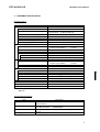
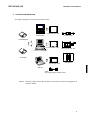
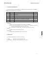
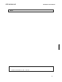
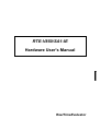
RTE-V850/SA1-IE
Hardware User's Manual
RealTimeEvaluator
RTE-V850/SA1-IE
Hardware User's Manual
CONTENTS
1.
INTRODUCTION ................................................................................................................2
2. MAIN FEATURES ..............................................................................................................3
3.
HARDWARE SPECIFICATION ..........................................................................................4
4.
SYSTEM CONFIGURATION ..............................................................................................5
5.
INSTALLATION..................................................................................................................6
6.
SETTING THE DIP SWITCH..............................................................................................7
7. DISPLAY LED ....................................................................................................................7
8. CONNECTING WITH THE USER SYSTEM .......................................................................8
Switching power on .......................................................................................................................... 8
Switching power off.......................................................................................................................... 8
9. PRECAUTIONS................................................................................................................10
Precautions for connecting the user system.................................................................................... 10
Handling the RTE-V850/SA1-IE...................................................................................................... 10
Confirming connection with the host system ................................................................................... 10
Differences between the RTE-V850/SA1-IE and the V850/SA1 (real chip)....................................... 10
Cautions related to delay time........................................................................................................ 11
NQPACK set consumables ............................................................................................................ 11
1
RTE-V850/SA1-IE
Hardware User's Manual
1. INTRODUCTION
The RealTimeEvaluator-V850/SA1-IE (hereafter called the RTE-V850/SA1-IE) is an in-circuit emulator
for the NEC RISC microcomputer V850/SA1.
Using a dedicated emulator chip in the RTE-V850/SA1-IE
has made it highly transparent, compact, and lightweight.
The RTE-V850/SA1-IE is supported by two debug monitors, GHS's Multi and Kyoto Microcomputer's
PARTNER. Users can select either debug monitor according to the operating environment of their system.
Both monitors run on Windows 95.
The host system for the RTE-V850/SA1-IE must be the PC98 series or DOS/V machine that has the
environment in which either of the debug monitors mentioned above can run.
The host system and the
RTE-V850/SA1-IE are connected via the interface card for a dedicated PCMCIA card or for the desktop
machine.
The RTE-V850/SA1-IE is supposed to come with the following items. Make sure that you received all
these items.
1. RTE-V850/SA1-IE main unit : One each
2. RTE for Win32 setup disk
: One each
3. User's manual
:
One each
4.
:
One each
5. RTE-PS01 power supply unit :
One each
6. NQPACK set
One each
Grounding clip
:
In addition to the above items, the following are required in using the RTE-V850/SA1-IE. They are not
standard accessories.
7. Interface kit (interface card and cable set) selected from:
•
PC card interface kit
•
PC98 desktop PC interface kit
•
DOS/V desktop PC interface kit
8. Debugger selected from:
•
GHS C + Multi + Midas server
•
PARTNER/Win
2
RTE-V850/SA1-IE
Hardware User's Manual
2. MAIN FEATURES
One of two source-level debuggers can be selected.
Users can select either Multi of Green Hills Software (GHS) or PARTNER of Kyoto Microcomputer.
GHS's Multi supports seamless debugging in an C/C++ integrated environment.
Meanwhile,
PARTNER supports the C language of both GHS and NEC (CA850), allowing users to set up the tool
environment as they like.
Both debuggers are provided with sufficient functions as a high-level language debugger. Simply
clicking the mouse on the source enables running programs, setting break points, and inspecting variables.
Highly transparent emulation functions are provided.
Use of a dedicated emulation chip in the RTE-V850/SA1-IE enables controlling emulation without using
functions in the V850/SA1. Almost all signal lines can be connected directly to the chip. As a result, the
emulation functions are provided with both functionally and electrically high transparency.
The standard configuration provides a sufficient emulation memory capacity.
The standard memory configuration of the RTE-V850/SA1-IE matches 256 Kbytes of ROM and 8
Kbytes of RAM internal to the V850/SA1 and 2 Mbyte of memory external to the V850/SA1. Any area can
be accessed with no wait state.
A realtime trace function is provided.
The RTE-V850/SA1-IE has a realtime trace function useful in debugging a built-in system.
The
realtime trace function can trace 32K cycles of any types including internal memory access cycles, as
driven by events.
A dedicated communication card is available for communication with the host.
Three different communication cards are available. The PC card usable in the RTE-V850/SA1-IE is a
Type-2 card specified in PCMCIA Ver2.1/JEIDA Ver4.2. It can be used in the PC98 series and DOS/V
machine that have a card slot.
In desktop machines, cards based on the C bus and ISA bus can be used.
3
RTE-V850/SA1-IE
Hardware User's Manual
3. HARDWARE SPECIFICATION
Emulation section
Target device
Emulation function
Clock frequency
Clock source
V850/SA1
Internal ROM emulation capacity
Internal RAM emulation capacity
External memory emulation capacity
External memory mapping unit
Memory mapping type
Break function
Event setting
Step break
Manual break
Fail-safe break
Write protection
Guard area
Trace function
Event setting
17 MHz
Automatic switching between external and internal
clocks (internal: 17 MHz/32.768 kHz)
256 KB
8 KB
2 MB
64 KB*1
RAM, ROM, GUARD, USER
Execution address condition : 14 points
Access cycle condition
: 4 points
Available
Available
Available
Available
Trace memory
Trace delay
Time measurement function
Measurement start
Measurement stop
Resolution
Maximum measurement time
Number of functions
Internal RAM realtime display
Pin mask function
Bus timeout function
Voltage operating range
Execution address condition : 2 points
Access cycle condition
: 3 points
150 bits x 32K words
0-7FFFh
At the beginning of execution
Till the occurrence of a break
2 CPU clock cycles
2*232 CPU clock cycles
1 ch
1 KB
RESET, NMI, WAIT-, HLDRQ
Available
3.3 V
*1 0x000000-0x0fffff: 1 MB in 64 KB units, 0x100000-0xffffff: 1 MB in 64 KB units or one block (1
MB) only
Host and interface sections
Item
Target host machine
Debug monitor
Interface
Power supply
Description
PC-98 series
DOS/V machine
GreenHills
: Multi
Kyoto Microcomputer : PARTNER/Win
PC card Type-2 (PCMCIA Ver2.1/JEIDA Ver4.2 or higher), C bus, and
ISA bus
AC adapter (input = 100 V and output = +5 V, 2 A)
4
RTE-V850/SA1-IE
Hardware User's Manual
4. SYSTEM CONFIGURATION
The system configuration of this product is shown below.
PC98 interface card
PC98 series
Power supply
PARTNER/Win
PC-AT interface card
RTE-xxxx-IE main unit
PC-AT or compatible
GHS Multi
PC interface card
NQ pack set
Note PC
Cable
(accompanying the interface card)
Remark
Each PC system must be able to offer an environment in which the debugger to be
used can operate.
5
RTE-V850/SA1-IE
Hardware User's Manual
5. INSTALLATION
The product is installed according to the following procedure.
1.
Installing the interface card
→ Refer to the applicable manual for the interface card to be used.
2.
Installing RTE for Win32
→ Refer to the applicable manual for RTE for Win32.
3.
Initializing RTE for Win32
(1)
Start chkrte32.exe, and initialize the following parameters.
RTE :
V850/SA1-IE
I/F-1 :
<<Specify the interface card you want to use.
I/F-2 :
<<Specify an IO port as required.
→ Refer to the applicable manual for RTE for Win32 for details.
4.
Installing the debug monitor
→ Refer to the applicable manual for the target monitor.
5.
Connecting with the user system
→ See Section 8 in this manual.
The setup of this system (exemplifying use of the PC card) is shown below.
Dedicated AC adapter
RTE-V850/SA1-IE main unit
100 VAC
Midas lab
Real Time Evaluator
V
POWER
USER POWER
PC card interface
User interface section
Grounding clip
8
5
6
RTE-V850/SA1-IE
Hardware User's Manual
6. SETTING THE DIP SWITCH
A switch on the back of the RTE-V850/SA1-IE is used to specify the emulation mode. It should be set
according to the configuration of the user system.
SW1
Symbol
Function
Initial value
1
Factory use
Always ON
ON
2
Factory use
Always OFF
OFF
3
Factory use
Always ON
ON
4
Factory use
Always OFF
OFF
5
Factory use
Always ON
ON
6
CLKAUTO
Used to switch the clock supplied to the V850/SA1
OFF
7
No use
Always OFF
OFF
8
Factory use
Always ON
ON
[CLKAUTO]
This switch contact is used to switch the clock supplied to the V850/SA1.
OFF: The clock pulse is supplied from the user system if it is connected.
If the RTE-
V850/SA1-IE is used standalone, its internal clock is used.
ON:
The internal clock is always used. (The internal clock frequency is 17 MHz.)
[No use]
This switch contact should always be set to OFF.
[Factory use]
This switch contact should always be set to the initial value.
7. DISPLAY LED
The following LEDs are on the top surface of the main unit.
POWER
:
USER POWER :
Lights when the RTE system power is on.
Lights when power is supplied to the user system.
7
RTE-V850/SA1-IE
Hardware User's Manual
8. CONNECTING WITH THE USER SYSTEM
Connect the RTE-V850/SA1-IE with a personal computer while referring to the applicable manual for
the interface kit used between them.
To connect the RTE to the user system, first install its accompanying NQPACK in the user system while
referring to the NQPACK technical document, then connect the RTE-V850/SA1-IE.
[Caution]
Before connecting the CPU section, attach a grounding clip leading to the RTE-V850/SA1-IE
main unit to a signal ground of the user system.
Switching power on
1.
Switch on power to the host personal computer.
2.
Connect a power supply dedicated to the RTE to the power supply jack of the RTEV850/SA1-IE.
3.
Switch on power to the user system.
4.
Start the debug monitor.
Switching power off
1.
Exit the debug monitor.
2.
Switch off power for the user system.
3.
Remove the power cord from the RTE-V850/SA1-IE power supply jack.
4.
Switch off power for the host personal computer.
[Caution]
When connecting the RTE-V850/SA1-IE to the user system, take care about pin 1. If the
connection is incorrect, all connected devices may get damaged.
The following figure shows how the RTE-V850/SA1-IE is connected to the user system. For details of
the PACK, refer to its accompanying technical document.
8
RTE-V850/SA1-IE
Hardware User's Manual
Tip of the RTE-V850/SA1-IE
1 pin
Type-F YQ socket
YQ pack guide screw
To a ground
Solder
YQ pack
NQ pack
User system
9
RTE-V850/SA1-IE
Hardware User's Manual
9. PRECAUTIONS
This section summarizes the precautions you should observe when using the RTE-V850/SA1-IE.
Precautions for connecting the user system
1)
Do not use the RTE-V850/SA1-IE with the user system power switched off. Otherwise, the user
system may get damaged or fail to operate normally.
2)
After the user system power is switched off, if you want to continue using the RTE system, basically
restart it from scratch.
3)
Otherwise, the RTE system may hang up.
If the processor in the user system fails to operate normally (because, for example, a reset is active),
the RTE system may also fail to start up or may hang up with specific commands.
Handling the RTE-V850/SA1-IE
[Warning]
Do not touch the exposed device on the top surface of the main unit by bare hands. It gets very
hot.
If you touch it, you may get burned.
[Caution]
The electrodes of the device are connected to the internal power supply. Do not touch it with
any electrically conductive stuff.
Otherwise, the main unit may get damaged.
Similarly, do not touch exposed socket pins at the bottom of the tip section with metal when
power is being supplied. Otherwise, the main unit may get damaged.
Confirming connection with the host system
Immediately after installation, run chkrte32.exe to select and set up the host interface card and RTE
system, then perform connection tests.
Refer to the RTE for Win32 Installation Manual for details.
Differences between the RTE-V850/SA1-IE and the V850/SA1 (real chip)
The real chip does not output CLKOUT immediately after it is reset, while the RTE-V850/SA1-IE
outputs CLKOUT.
If the user system uses CLKOUT, set software so that CLKOUT is output when the
software is stored in ROM.
The real chip allows the memory address output mode register (MAM) to be read and written, while the
RTE-V850/SA1-IE allows the resister only to be written.
For the RTE-V850/SA1-IE, the subclock is factory-set to 32.768 kHz. Note that an oscillation circuit
on the target is not used. Also note that P114, the dual-function pin for XT1, is used as a normal input port
even if the subclock is used.
10
RTE-V850/SA1-IE
Hardware User's Manual
Cautions related to delay time
Almost all signals are connected directly between the CPU in the IE and the user system (see Appendix
B). However, a delay of about 3 ns (typical) may occur due to the wiring length required in getting to the
tip and the capacity, compared with direct CPU connection. The user system must be designed so as to
accommodate this delay.
NQPACK set consumables
(1)
100-pin type-F YQ socket
YQS-100SDF
(2)
100-pin YQ pack
YQP-100SD, with guide screws
(3)
100-pin NQ pack
NQP-100SD
[Remark]
The sockets shown above are consumables. They should be replaced regularly, for example
after about 50 cycles of insertion/removal.
However, a soldered socket at the lower surface of
the RTE-V850/SA1-IE cannot be replaced. If it is expected that it is subjected to frequent
insertion/removal, install a 100-pin YQ socket previously for protection purposes.
11
RTE-V850/SA1-IE
Hardware User's Manual
- Memo -
RTE-V850/SA1-IE Hardware User's Manual
M763MNL01
Created on November 10, 1997. Rev1.00
12