1
HIPLM User Manual
A general user guide
v.1.0
By
Dominic Carrier
&
Dominic Lepage
Last updated: 15th September 2012
Table of contents
Introduction ......................................................................................................................................... 1
General introduction to the hyperspectral system ................................................................................... 1
Hyperspectral Imaging .............................................................................................................................. 1
Conjugate-Space Imaging .......................................................................................................................... 2
User Manual – Common Tasks.............................................................................................................. 3
Step 1 – General Start-up Procedure ........................................................................................................ 3
Step 2 – Procedure for Spatial Imaging ..................................................................................................... 3
Step 3 – General Closing procedure .......................................................................................................... 5
Alternative Step 2 – Procedure for Conjugate Imaging............................................................................. 6
User Manual – Advanced Details .......................................................................................................... 7
Software Usage and Troubleshooting ....................................................................................................... 7
Operating Mode Switch (PL, EL and Fluo) ................................................................................................. 8
Routine Alignment Procedure ................................................................................................................... 8
Detailed description ........................................................................................................................... 10
Overview ................................................................................................................................................. 10
Laser floor ................................................................................................................................................ 12
Beam homogeniser platform .................................................................................................................. 14
Microscope tower ................................................................................................................................... 18
Imaging module ....................................................................................................................................... 21
Hyperspectral box ................................................................................................................................... 23
Appendix 1 - HIPLM control with PHySpec .......................................................................................... 25
Adding the HI device ............................................................................................................................... 25
Adding the camera .................................................................................................................................. 25
HI control ................................................................................................................................................. 25
Acquisitions ............................................................................................................................................. 26
Cube rectification .................................................................................................................................... 26
HIPLM User Manual
Introduction
General introduction to the hyperspectral system
The hyperspectral photoluminescence mapper (HIPLM) is a specially modified microscope system.
The instrument captures 2D images of a sample (XY image) spectrally dispersed in a 3rd dimension as a
function of the collected light’s energy (E). The final images produced by the system are stored within a
cube of data, generating a “hyperspectral” cube in which each volume pixel (voxel) corresponds to a
coordinate in (x, y, E).
Although this process is conceptually quite simple, the technique employed to produce those images
rapidly, efficiently and with great quality is not as straightforward. The hyperspectral measurement
process will be explained in the next sub-sections.
Alternatively the HIPLM system installed in the Laboratory for quantum semiconductors and photonbased bionanotechnology (QS-Group) possesses a second imaging mode of operation. In the normal
mode of imaging, the images recorded by the camera are direct images of the sample, which
corresponds to a XY image. The second imaging mode, called Conjugate-space imaging, modifies the
light's path inside the HIPLM system and allows the camera to observe the angular distribution of the
light emitted by the inspected elements, a kxky image instead of a XY image. This imaging mode is
discussed in last sub-section of this introduction.
Hyperspectral Imaging
An hyperspectral image is a collection of greyscale 2D images, where each image expresses the
intensity distribution of a specific wavelength. Instead of taking one intensity image for the whole
spectrum (as a normal camera would), each image is first sent through a special spectrometer, in order
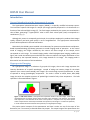
to separate its energy (wavelengths) components. The result is similar to a Red, Green, Blue (RGB)
image, but with the complete spectrum of probed light instead of only three components. The RGB
separation is illustrated below in figure 1.
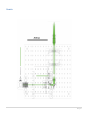
Figure 1 - RGB color scheme - Conceptual color separation within a full color image. Each color is
represented with an intensity image, where the white color represents a full intensity, and a black
color represent a total absence of the color at that position. Computer uses only three specific
colors to represent the commonly used visible color spectrum, but as light is a continuous spectrum,
it can be measured and stored much more precisely in an hyperspectral image.
The precise optical concepts of the spectrometer and how it works are out of the scope of this
document, but it is necessary to describe what they output. The output image of the spectrometer has
1|26
the same morphology as the input one, which means that there is a direct correspondence between the
input and output pixels. That said, the snapshots produced by the system during the measurements are
not an intensity image at a specific wavelength (as illustrated in the left part of figure 2), but a
continuous image in wavelength along the x-axis (figure 2, right part).
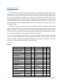
Figure 2 - Hyperspectral imaging - The left part illustrate the final output of the HIPLM system, consisting of a
sequence of images, where each image represent the intensity distribution of the light at that specific wavelength.
The right part illustrates the snapshot taken by the HIPLM system at a specific central wavelength, before postprocessing into the final hyperspectral image. The snapshots are called "unrectified" images, since the x-axis is
multiplexed with its wavelength content.
Conjugate-Space Imaging
For the readers unfamiliar with the Fourier transform and its application in optics, the concept could
by simplified by stating that instead of observing the spatial disposition of the objects in the image, this
secondary mode of operation observes at which angle the light is reflected/emitted/scattered by all the
object in the image. The polar and azimuthal angles of scattering are therefore mapped as a function of
energy. This mode of operation is therefore quite practical for the direct measurements of the
dispersion relation of any light. The schematic in figure 3 illustrates this concept.
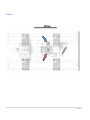
Figure 3 – Schematics of Conjugate-space
Imaging - All the light emitted from a
specific point on the object will collect to
an image point in the real imaging (left),
whereas all the light emitted from a
specific angle from all parts of the object
will collect at a specific position in the
Fourier plane (right).
2|26
User Manual – Common Tasks
Step 1 – General Start-up Procedure
All the procedures of this guide consider that the user is comfortable with the usage of the related
software, but mostly the PHySpec software, as it is necessary in the sample's alignment. If not, see
Appendix 1 for basic details of operation , consult the respective software manual for further details or
ask the laboratory manager.
•
•
•
Log-in the system and inscribe details in the logbook
Check the workstation for anomalies (abandoned liquids / samples). If required:
o Safely dispose and clean the workstation
o Make note the anomalies in the logbook
o Email the lab manager regarding the anomaly
Check that all the equipment is correctly powered on
o Keithley voltmeter
o SC-10 Shutter control (shutter closed)
o Power bar of the hyperspectral imager and Apogee camera (identified)
o Laser(s) (if required), at the appropriate power. Follow the laboratory laser safety
procedures at all times.
o White light lamp intensity(if required)
Step 2 – Procedure for Spatial Imaging
1 – Sample Alignment and Focus
•
•
•
•
•
•
•
•
•
•
•
•
Put on clean nitrile gloves
Place the sample on the stage, under the microscope objective
Open PHySpec, initialize the system and load the latest calibration files
Open the white light lamp up to an appropriate intensity (up to half the maximum is good)
Set the HI to 760nm if imaging in the NIR; 760nm is an appropriate wavelength to be able to
simultaneously see a large portion of the image with the white light.
Adjust if imaging in the VIS.
Start the "Video mode" of the camera to about 1 sec exposure (gives a good trade-off between
FPS and brightness for most QW samples).
Roughly adjust the focus to allow the observation of features on the sample or sample holder
Move the sample with the XYθ stage until it is completely visible in the image display (or
appropriately positioned for the experiment)
Adjust finely the focus using the Z-stage to obtain the sharpest image possible of the sample's
surface
Stop the "Video mode" of the camera
Turn off the white light lamp
3|26
2 – Optimal parameters evaluation
•
•
•
•
Align sample and adjust focus (described previously)
Before proceeding with the hyperspectral image acquisition, it is important to set-up the
following parameters:
o Camera binning
o Set the camera resolution to 16bits
o [Optional] Camera temperature control: should not be set to below 2°C for extended
period. Lower values will causes condensation and formation of ice crystals on the
camera front glass.
Determine the appropriate acquisition time
o Move the HI grating to the sample's emission wavelength, and manually open the laser
shutter
o Adjust the laser power to the wanted value, if not already selected.
o Select the "Manual" acquisition mode and produce a single image exposure
o Adjust the acquisition time and repeat exposure to obtain the highest intensity without
producing image saturation (use the cursor tool to check the intensity of the bright
zones). Saturation occurs at a value of about 216, or 65535. The higher the average
intensity of your image, the better signal-to-noise ratio you will get. The noise floor is
dependant of the camera temperature, but it lies around 1200-1400 intensity unit, with
a typical variance of about 150.
o Close the laser shutter
Once your acquisition time is determined, acquire a dark image measurement. This single image
is used to get the average background noise of the CCD.
o Select the "Dark" acquisition mode
o Adjust the exposure time (identical to the final measurements)
o Select the number of images to acquire in order to obtain the camera thermal
background noise profile (the images will be averaged). Usually, the shorter the
exposure, the higher this number will be. Below a 5 sec exposure, we suggest at least 11
to 21 images. At longer exposure, reduction to about 3-5 is tolerable.
o Save the Dark Image (In the image display, select "File > Save Image")
3A – Single Measurement – PHySpec
•
•
•
•
Align sample and adjust focus (described previously)
Evaluate optimal acquisition parameters (described previously)
Load the latest calibrations files (if not done previously)
Proceed with your sample acquisition
o Select the "Automatic" acquisition mode
o Setup the desired acquisition wavelength range and step size between images
o Setup the acquisition time
o Specify the cube name and description details
o Open the laser shutter
o Start the acquisition
4|26
•
•
o Upon completion of the acquisition, close the shutter
Export data
o Right-click on the cube name and rectify the cube
o Right-click on the cube to get a preview of the rectified cube in PHySpec
o [Optional] Export the RAW data (File > Export Cube...)
o Export the Rectified data (same window)
o Save the Dark Image (Open the dark image display > File > Save Image)
[Optional] Post-processing steps
o Refer to the PHySpec user manual for the post-processing capabilities of the software
3B – Multiple hyperspectral measurements – LabView program
•
•
•
•
•
•
•
•
Align sample and adjust focus (described previously)
Evaluate optimal acquisition parameters (described previously)
Close PHySpec
Open the LabView program
Load the latest calibrations files (if not done previously)
Setup the acquisition parameters in the Acquisition Window
Specify the output folder
Start the acquisition
3C – Real-Time hyperspectral snapshots – Matlab program
•
•
•
•
•
•
•
Align sample and adjust focus (described previously)
Evaluate optimal acquisition parameters (described previously)
Before closing PHySpec, setup the HI wavelength to the desired central wavelength
Close PHySpec.
Open the Matlab program
Setup your acquisition parameters
Start the acquisition
Step 3 – General Closing procedure
•
•
•
•
•
•
•
Put on clean nitrile gloves
Remove all samples and liquids from the HIPLM stage
Make sure to properly clean all spills
Check the workstation for samples or garbage and make sure to dispose of your tools, samples
and liquids and to clean the workstation for the next user.
Close ALL the box doors correctly
Check that all the fragile equipment is correctly powered off
o Laser(s)
o White light lamp
o Peristaltic pump
o Laser shutter is on the closed state or turned off
Log-off the system and inscribe details in the logbook
5|26
Alternative Step 2 – Procedure for Conjugate Imaging
As mentioned in the introduction, the HIPLM system allows for the imaging of the conjugate (Fourier)
space of an image, thus allowing the direct observation of the angular emissions of a sample. The
procedure to do so is as follow, and supersedes or adds to the previously defined "Step 2 – Procedure
for Spatial Imaging". The following procedure is a guideline only, and you should consult the laboratory
manager prior to engaging in any conjugate imaging experiments. Refer to the Imaging module
schematics for more information.
1 – Sample Alignment and Focus
The sample alignment and focus steps are exactly identical to the procedure described in the spatial
imaging section. As the conjugate imaging is non-trivial, alignment and focus in the conjugate space is a
challenge at best, so those steps are done in the real space before switching to the Fourier space.
Added – Imaging Mode Switch
After the sample is aligned, the trained HIPLM operator will switch the system from the Spatial
imaging mode to the Angular imaging mode. Consult the "Switching the Imaging Mode from Real to
Fourier Space" section.
2, 3A-3C – Parameters evaluation and Image acquisition
Once the switch in operation mode is completed, from this point on the procedure of parameters'
adjustment and image acquisition is identical to the previous section ("Step 2 – Procedure for Spatial
Imaging", subsection 2, 3A, 3B and 3C). Conceptually, the image acquisition procedure stays the same,
even if the image in itself was modified by a switch to the optical light path.
Details – Switching the Imaging Mode from Real to Fourier Space
The following steps should be done by trained personnel only, as the kinetic mirror is located in the
midst of very sensitive optical elements. Touching any of those elements may misalign the whole
system or produce visual artefacts in the output image.
Those steps are written here as a reference. EXTREME CARE is required.
•
•
•
•
Put on clean nitrile gloves and make sure to button your lab coat’s sleeves.
Open the side-door of the HIPLM box, giving access to the homogenization stage and the mirror
floor
With the permission of the lab manager, slide the right hand OVER the imaging mirror (blue
arrow in schematics) until the index or major finger touches the TOP of the kinematic mirror (red
arrow in schematics).
While holding the mirror mount, FLIP DOWN the kinematic mirror (red arrow) to go from RealSpace imaging to Conjugate-Space imaging (flip up the mirror to come back to Real-Space
imaging).
o The kinematic mirror is spring-actuated. DO NOT let the mirror go freely. Use the hand
to accompany the mirror all the way down or up, while twisting the wrist around the
imaging mirror (blue arrow).
6|26
o
•
•
Take extreme care to NOT touch the imaging mirror (blue arrow). Any dust, scratch or
irregularity WILL BE imaged directly by the camera, thus greatly degrading the output
image quality.
Remove the hand from the system while avoiding the imaging mirror (blue arrow)
Carefully close the side door of the HIPLM box, making sure there is no gap left
User Manual – Advanced Details
Software Usage and Troubleshooting
PHySpec (v.1.15.1)
•
•
•
•
Make sure the HI was correctly initialized (distinctive noise and status message in the
application)
Make sure the camera was added to the software (under the menu: Camera > Add Camera ;
selecting the Apogee driver should identify the camera to add or display "Already Added")
Make sure the latest calibration files are loaded.
Consult the PHySpec software manual for its specific usage.
LabView Multi-Acquisition
•
•
•
All the required equipments are initialized automatically. You should hear the HI system
initializes (buzzing sound of a stage moving to its extrema 3 times) and hear the Keithley
voltmeter initializes to its pre-recorded default configuration (with two loud beeps).
If no error were displayed, the system should be ready to go.
Consult the LabView software manual for its specific usage.
Matlab Real-Time Pseudo-Imaging
•
•
The scripts automatically initialize and load the required equipments. If no errors were
displayed on the command prompt and asks the user to proceed, the program is ready to work.
Consult the Matlab scripts documentation for its specific usage.
Troubleshooting
Those steps describe ways to reinitialize the system to a known and working condition, in the case a
software problem arises. They should be done IN THE SPECIFIED ORDER, as the risk of damaging or
misaligning the system increases with each step.
•
•
•
If the HI imager, the camera, the shutter control or the Voltmeter did not add correctly, verify
that the equipment is correctly powered on; try to restart the application.
If the problem persists, try to reboot the computer. The communication ports may get stuck,
and a reboot will clear the system's ports
If the problem persists, try to power-cycle the hardware. If accessible, use the power button or
the power key. If the power button is not accessible (for the HI and camera), use the switch on
the power bar to cut down the power for about 15 seconds before activating it again (be sure to
7|26
•
choose power bar dedicated to those equipments). As the camera and the HI are sensitive
equipment, they should never be powered down while executing a task.
If the problem persists (for the HI), ask the designated lab technician to do a power-cycle of the
HI using the switch inside the box. DO NOT ATTEMPT this yourself. The switch is located close
to optical components; touching them may misalign the system.
Operating Mode Switch (PL, EL and Fluo)
The HIPLM can be used for multiple applications. Those applications consist primarily in PL
(photoluminescence), EL (electroluminescence) and Fluo (fluorescence). In order to increase the quality
of the measurements, it is possible to fine-tune the utilized optical components to collect more light or
filter undesired light. The two main optical components to change are the beam splitter and the
collection optical filters (located after the microscope turret and the beam splitter).
Since changing between those operating modes requires modifying optical components, alignment of
the beam splitter and a spectral calibration are necessary after each modification. Refer to the
schematics of the Microscope tower for more information.
If necessary:
•
•
Change beam splitter in cage cube (red arrow): Hot/cold mirror, beam splitters, etc.
Change Optical filters (blue arrow): Laser filters, thermal noise filters, VIS/NIR filters, etc.
Routine Alignment Procedure
Those procedures are destined to the trained personnel in charge of maintaining the HIPLM system.
They should not be attempted by an untrained user.
Spectral Calibration
The following procedure describes the way to do a spectral calibration and its related calibration files.
Those are necessary for yielding acceptable precision in the measurement and rectification process of
the hyperspectral images.
•
•
•
•
•
•
•
•
•
•
Remove the goniometer from the XYθ stage
Make sure the laser shutter is closed
Put on clean nitrile gloves
Carefully remove the optical filters, located after the microscope turret and the beam-splitter
On the XY stage, install the calibration lamp (Neon lamp), using the provided optical post and
screw, right below the microscope objective (preferably 10x)
Over the lamp, insert the diffuser and the small sheet of white paper (for better diffusion)
The Z-adjustment should bring the white paper sheet quite close to the microscope objective
(not more than 5mm to 1cm away), out of focus of the objective (again for diffusion purpose).
Turn on the neon lamp
Open PHySpec
Start the calibration sequence for both gratings, using a 10 sec acquisition time and the default
settings for CCD and pixel size (see PHySpec software manual for details)
8|26
o
•
•
•
•
•
Using a dielectric hot-mirror as a beam-splitter may cause intensity variations in the
Neon peaks. Those variations may confuse the calibration algorithm. Be sure to use the
adequate reference calibration file, associated to the installed beam-splitter/mirror
Verify the calibration by moving the HI to spectral lines and verifying that the image at that point
is centered on the line. Suggested lines:
o VIS grating line A: 585.249nm
o VIS grating line B: 724.25nm
o IR grating line A: 743.89nm
o IR grating line B: 885.09nm
Export the calibration files to the latest calibration folder (c:\HIPLM\Latest Calibrations\)
Turn off the Neon lamp and remove it from the XY-stage
Carefully reinstall the optical filters (if required by the operating mode)
Reinstall the goniometer on the XYθ stage.
Angular Alignment
Changing the beam-splitter requires a simple realignment of the system, in order to have the
microscope objective image projected appropriately on the CCD.
•
•
•
•
•
•
•
•
•
•
Put on clean nitrile gloves
Turn on the white light lamp and place a white paper sample on the stage
Do a rough positioning and focus of the paper sample (at 760nm, for example)
Switch the system's imaging mode to Conjugate Space (easier to align)
Using an appropriate Hex key, loosen the four screws of the beam-splitter cap, but do not
remove them completely (loosen by about half a turn to a turn)
Using your hand, turn the beam-splitter cap about 1/8 of a turn (45°) in either direction. This
should bring the cap to a position where it will be possible to remove it by sliding it out
Slide out the beam-splitter cap and its attached beam-splitter/mirror. Be careful to have a linear
lateral movement (perpendicular to the cap) to prevent the optical component to touch the side
of the beam-splitter box
Take the new beam-splitter cap and new optical component (mirror or beam-splitter) and insert
them in the beam-splitter box, preventing the optics to touch the box's sides
Rotate the cap assembly of about 45 degree until the image is back within the CCD field of view
(using the "Video Mode")
Carefully align the white visible circle within the frame of the image. The center of the circle
should coincide as much as possible with the center of the image.
o To align vertically, only carefully rotate the cap assembly within the beam-splitter box
socket. Slight movement will have a amplified effects, so a minute manipulation is
required.
o To align horizontally, you will have to pull out the assembly and adjust the mirror's
inclination in relation to the beam-splitter cap. Great care must be taken so that the
surface of the mirror coincides with the center of the beam-splitter cap, so that the
9|26
•
•
•
•
•
projected image is centered on the optical axis before but also after the beam-splitter
assembly.
Once adequately aligned, hold the cap in place with one hand while you tighten back the screws
to fix the cap assembly back in place.
Verify that the alignment is still adequate after tightening the screw. Correct if necessary
Close the while light lamp and remove the white paper sample
Switch the system back to the Real-Space imaging mode
Proceed with a full spectral calibration (mandatory)
Detailed description
Overview
Description
Due to its multipurpose applications, the HIPLM system is composed of several modules which can be
adjusted independently. Each of those modules is to be aligned on their own and between themselves if
the system falls out of alignment.
The system is divided into five modules: First the Laser floor, where all the light sources are installed.
The light pump used for PL or fluorescence is then coupled into the second module, the Beam
homogeniser platform. This platform enables a homogeneous illumination of the substrates over the
field of view. It is also possible to switch the illumination to a single hot spot on this floor. The
Microscope tower is the third section, where most of the collection and injection optics is installed along
with interchangeable filters. The lower section of the Microscope tower is only sector that should be
accessible to the unspecialized HIPLM users. The collected PL or EL from this tower is then sent to the
Imaging module, where the advanced user can switch to the conjugate space imaging for SPR studies.
The last module consists of the Hyperspectral box containing the Volume Bragg Grating from Photonetc
Inc and the Apogee Camera. Each module will be discussed in more details in the coming sections.
10 | 2 6
Schematics
11 | 2 6
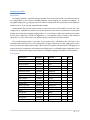
Laser floor
Description
The laser floor is designed to support four (4) different illumination sources, which can be employed
as various PL pumps or fluorescence. Each source is coupled to a pair of mirrors mounted on a standard
and kinetic (flipper) mounts. Those are employed to align independently each source with the last two
mirrors of the laser floor. These last two mirrors are aligned with the rest of the system and should NOT
be disturbed when installing a new source. All the sources are finally coupled into a multimode optical
fibre (not shown) and led to the Beam Homogenizer.
To switch between light sources to another, open the side of the environmental box and select the
kinetic mirror corresponding to the desired light source.
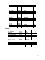
List of parts
Description
Flipper mount
Thread adapter
Height spacer
Mirror
Height spacer
Cage plate
Cage rod
Laser filter
Mirror mount
Mirror mount
Mounting base
Post mounting
Breadboard
Mounting base
Lens tube
Lens tube
DPSS Laser 1
Supplier
Newfocus
Thorlabs
Thorlabs
Thorlabs
Thorlabs
Thorlabs
Thorlabs
Thorlabs
Thorlabs
Thorlabs
Thorlabs
Thorlabs
Thorlabs
Thorlabs
Thorlabs
Thorlabs
Viasho
Part No.
9891M-L
AP6M4M
BA2S7/M
BB1-E02
CLCPB1/M
CP08/M
ER6
FL532-10
KCB1
KS1
LCPB1/M
MA4/M
MB6090/M
PB2/M
SM1L05
SM1T20
VA-II-N-532
QTY
3
3
4
8
4
4
4
2
1
4
4
4
1
7
2
1
1
12 | 2 6
Schematics
13 | 2 6
Beam homogeniser platform
Description
The beam homogeniser is a complex module designed to generate a uniform illumination at the field
of view of any microscope objective and thus, independently of the laser source. The functioning is
illustrated in the “Principle of beam homogenization” subsection and goes roughly as follows:
A) A laser source is coupled into the multimode fibre. Most lasers have a pseudo-Gaussian spatial
distribution I(x) and a sharp angular/wavevector distribution in I(k). The phase of laser beam
ϕ(x,k) is almost unique (coherent).
B) After the 5m of the multimode fibre, independently of the input, the spatial distribution I(x) is a
Gaussian defined by the fibre coupler. However, speckle pollutes the distribution, as natural
coherent interferences statistically occur. The wavevectors of the light are cleaned and is virtually
collimated, due to the fibre size and the collimation system. The phase ϕ(x,k) is now randomized.
C) The rotating diffuser is placed after a lens where the wavevectors are broadened. Following the
rotating diffuser, the spatial distribution is still the same, but the wavevector distribution is
broadened and the speckles time averaged (60hz).
D) A kaleidoscope is place at the focal point of a secondary lens, which projects a time smoothed
spatial Gaussian at the kaleidoscope input. The time-independent speckle is now in the
wavevector space.
E) At the kaleidoscope output, a spatially distributed flat-top (2%) illumination is present. The phase
ϕ(x,k) is further randomized. The time-independent speckle effect is distributed between the
two planes (spatial I(x) and conjugate I(k)) and minimized by the time-average.
F) A collection optics resizes the beam and projects the appropriate object at the back focal plane of
the microscope objective. A flat-top (2%) can then be projected at the objective’s field of view.
The translation stage can be moved to take the rotating diffuser and the focusing lenses out of the
optical path. This will result in a focusing of the light source into a hot spot on the sample. This can be
employed for laser surface modifications or for alignment purposes.
List of parts
General:
Description
Rotating diffuser
Acromat lens
Acromat lens
Thread adapter
Thread adapter
Thread adapter
Mirror
Cage plate
Height spacer
Cage rod
Supplier
SUSS
Tholabs
Tholabs
Tholabs
Tholabs
Tholabs
Tholabs
Tholabs
Tholabs
Tholabs
Part No.
60-1105-911-000
AC254-075-A
AC254-100-A
AP25E6M
AP4M3M
AP6M4M
BB1-E02
CP08/M
CPB1/M
ER1
QTY
1
1
1
4
2
1
2
8
6
4
14 | 2 6
Cage rod
Cage rod
Cage rod
XY lens mount
Mirror mount
Kinematic mount
Best form lens
Best form lens
Translation stage
Breadboard
Breadboard
Mounting post
Mounting base
Post Spacer
Mounting base
Lens tube
Lens tube
Translation Mount
Translation Stage
Tholabs
Tholabs
Tholabs
Tholabs
Tholabs
Tholabs
Tholabs
Tholabs
Tholabs
Tholabs
Tholabs
Tholabs
Tholabs
Tholabs
Tholabs
Tholabs
Tholabs
Tholabs
Tholabs
ER10
ER12
ER4
HPT1
KCB1
KMCP/M
LBF254-050-A
LBF254-100-A
LT1/M
MB2025/M
MB3045/M
P1
PB2/M
PS5/M
SCPB1/M
SM1T20
SM1V05
SM1Z
TBB0606/M
12
4
4
1
2
1
3
1
1
1
1
4
1
1
2
1
5
2
1
Kaleidoscope:
QTY
6
2
Thorlabs
Thorlabs
Thorlabs
Edmund
Edmund
Part No.
PS3
CP02/M
MAP1030100A
ACL2520-A
MB1015/M
NT64-915
NT65-835
Supplier
Thorlabs
Thorlabs
Thorlabs
Part No.
F220SMA-A
AD11F
M24L05
QTY
2
2
1
Description
1/2'' Mount post
Cage Plate
Supplier
Thorlabs
Thorlabs
Achromatic Doublet Pair
Aspheric Condenser
Breadboard
Rod mount
Silica Hex light pipe
1
2
1
1
1
Fibre setup
Description
SMA Collimation
SM1 Adapter
5m Multimode fiber
15 | 2 6
Principle of beam homogenization
16 | 2 6
Schematics
17 | 2 6
Microscope tower
Description
The microscope tower is where an important fraction of the HIPLM optics takes place. When using
the system for PL, the homogenized light pump comes at the top and passes through a hot mirror (or
cold for other uses) located in the cage cube. The pump reaches the microscope objective (MO) in place
where the transmitted light is homogeneous at the focal point of the MO. The emitted PL is collected by
the MO and reflected by the hot mirror in place. In EL mode, it is recommended to use a silver mirror for
a flatter broadband response. Appropriate filters are placed at the exit of the cage cube, such as laser
and thermal filters, and are indicated by the blue arrow in the schematics. The PL signal is then sent to
the Imaging module.
Common users have access to the lower section of the Microscope tower through two doors placed
in the environmental box. Users can change the MO by rotating the objective turret and position their
samples in XYZθφ, i.e. the 3 spatial axis, polar and azimuthal angles. Not indicated in these schematics
are the tubes coming in and out of the peristaltic pump, located outside the environmental box. Various
tubes reach the sample holder and are used to control injection of liquids.
Also, note that operating a mode switch (EL, PL, Fluo) or basic angular alignment of the system might
involve a change in beam-splitter (see Operating Mode Switch or Routine Alignment Procedure
sections). This filter is located in the cage cube, indicated by a red arrow in the schematics. Follow the
procedures described in the previous sections if this is necessary.
List of parts
General:
Description
Cover plate
Rotatable platform
Mirror
Cage cube
Cage adapter
Cage rod
Filter mount
Mirror mount
Best form lens
Shorpass filter
M.O. 10x
Hot mirror
Long pass
Objective turret
Mounting post
Mounting base
Post spacer
Supplier
Thorlabs
Thorlabs
Thorlabs
Thorlabs
Thorlabs
Thorlabs
Thorlabs
Thorlabs
Thorlabs
Edmund
Edmund
Edmund
Edmund
Thorlabs
Thorlabs
Thorlabs
Thorlabs
Part No.
B1C
B3C
BB2-E02
C4W
CP07T
ER4
FFM1
KCB2
LBF254-100-A
NT47-590
NT58-516
NT64-469
NT64-513
OT1
P30/M
PB2/M
PS3
QTY
1
1
1
1
2
4
1
1
1
1
0
1
1
1
2
4
1
18 | 2 6
Base plate
Thread adapter
Lens tube
Translation Mount
Thorlabs
Thorlabs
Thorlabs
Thorlabs
PT101
RMSA2
SM1L03
SM1Z
Description
Angle plate
Goniometer
Breadboard
Translation stage
Linear&Rotation stage
Supplier
Thorlabs
Thorlabs
Thorlabs
Thorlabs
Thorlabs
Part No.
AP90/M
GNL10/M
MB1515/M
PT1/M
XYR1/M
1
4
3
1
Stage:
QTY
1
1
1
1
1
19 | 2 6
Schematics
20 | 2 6
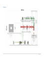
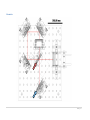
Imaging module
Description
The imaging module is accessible through the side of the environmental box. This platform is where
the imaging plane at the camera is decided between normal imaging, for standard XY mapping , or
conjugate imaging, for kXkY mapping. This later mode is employed for the construction of the dispersion
relation in I(E, kX, kY) of any light scattered under the MO.
As described in the previous section, there are two critical items in this module. The first one is the
imaging mirror, indicated by the blue arrow in the schematics. This mirror is positioned at a focal point
of both the normal and conjugate imaging modes: i.e. a real image is visible when placing a lens paper
on this mirror. While this is useful for alignments, it is an important source of noise in the measured
signal (PL,EL or Fluo): if this mirror is scratched or dusty, it will show in the collected data.
The second important part on this floor is the kinetic mirror, indicated by the red arrow in the
schematics. When this mirror is in the erect position, the light is directly sent to the imaging mirror and a
XY map is sent to the hyperspectral imager. When the mirror is down, the optical path is elongated as to
project the Fourier components of the MO to the imaging mirror. A conjugate space cartography is then
sent to the hyperspectral imager. The procedure for conjugate imaging is described in a section above.
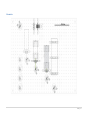
List of parts
Description
Flipper mount
Thread adapter
General clamp
Cage rod
Cage rod
Kinematic mount
Miror mount
Cage plate
Cage adapter
Mounting base
Breadboard
Nikon Tube lens
Mounting base
Mirror
Post spacer
Post spacer
Post spacer
Tube Lens Adapter
Supplier
Newfocus
Tholabs
Tholabs
Tholabs
Tholabs
Tholabs
Tholabs
Tholabs
Tholabs
Tholabs
Tholabs
Edmund
Tholabs
Tholabs
Tholabs
Tholabs
Tholabs
UdeS
Part No.
9892M-L
AP6M4M
CL5
ER3
ER4
KMCP/M
KS2
LCP01/M
LCP02
LCPB1/M
MB3030/M
NT58-520
PB2/M
PF20-03-P01
RS03
RS05
RS075
Homemade
QTY
1
1
2
4
4
4
4
1
1
1
1
1
7
5
4
4
7
1
21 | 2 6
Schematics
22 | 2 6
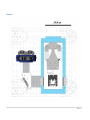
Hyperspectral box
Description
This last module contains Photonetc Inc hyperspectral imager (HI) and the CCD camera. The HI
contains two sets of Volume Bragg Gratings (VBG) which are designed to work from 400-740nm (VIS)
and 740-1000nm (NIR) respectively. The HI enables the spectral spreading of the image on the camera,
while preserving the XY or kXkY dimensions. Hyperspectral cubes are then reconstituted with the various
software programs presented in the sections above.
List of parts
Due to Non-Disclosure Agreements with Photonetc Inc, the authors will not specify the system in great
detail in this section. However, it is important for the advanced user and lab managers to know about
the following:
•
•
•
Input/Output tube-lenses: Nikon Tube lens (Edmund), part# NT58-520
Protected silver mirror employed inside the HI
The camera is an ALTA F32 from Apogee: the technical sheet is available here.
23 | 2 6
Schematics
24 | 2 6
Appendix 1 - HIPLM control with PHySpec
Figure A1.1 - PHySpec interface - Specific sub-windows are opened by selecting the appropriate tabs
on the left column and pressing the related button. The HI device control is found under "Devices >
HI000132000", the camera parameters under "Parameters > Apogee", and the acquisition window
under "Acquisition > Apogee".
Adding the HI device
•
•
Open the communication port (under the menu communication). This should be done
automatically when the program opens and it should detect automatically which port to use.
Open the device list and search for devices (menu "Devices > Devices list..." and button "Search
for devices"). Again, this should be done automatically at program startup.
Adding the camera
•
•
Select menu "Camera > Add camera..."
Select the appropriate driver and camera (in this case, Apogee and Alta U32 respectively).
HI control
•
In the Hyperspectral imager control window, input the desired central wavelength and press
"GO" to bring the HI grating in the adequate position. The display's central line should be
centered at the current wavelength if the calibrations are accurate.
25 | 2 6
Acquisitions
Manual
•
•
•
•
Select the manual acquisition mode in the Apogee acquisition window
Move the grating to the desired position
Select the exposure time
Press "Expose" for a single image, press "Video mode" for a continuous image feed
Automatic
•
•
•
•
•
Select the automatic acquisition mode in the Apogee acquisition window
Specify the wanted wavelength limits and step for your acquisition
On the Exposure tab, specify the exposure time for your images
Input a cube name for the acquisition run
Press "Start" to launch the acquisition sequence
Cube rectification
Upon completion of an automatic acquisition (a full unrectified cube), it is necessary to rectify it in
order to produce a practical hyperspectral image. To do so, right-click on the data button ("Data tab >
Cube name") and select rectify.
After rectification, it is important to save your data, by exporting them (menu "File > Export cube...").
26 | 2 6