1
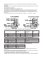
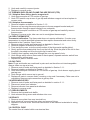
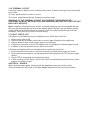
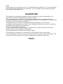
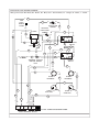
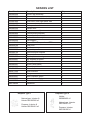
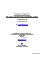
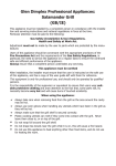
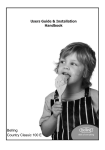
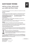
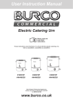
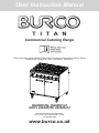
User Instruction Manual
T I T A N
Commercial Catering Range
These instructions cover the Burco Titan Dual Fuel 6 Burner Commercial Catering Range
RG90DF/NG, RG90DF/LP, SKU’s 444440350, 444440414
RG90DF/NG, RG90DF/LP
SKU’s 444440350, 444440414
Glen Dimplex Professional Appliances
Stoney Lane, Prescot, Merseyside, L35 2XW
Tel: 0844 815 3755
www.burco.co.uk
INTRODUCTION
This appliance must be installed by a competent person in compliance with the installation
and servicing instructions and national regulations in force at the time.
Particular attention must be paid to the following:
Gas Safety (Installation & Use) Regulations.
Health and Safety at Work etc Act.
Adjustment must not be made by the user to parts which are protected by the
manufacturer.
Users of this appliance should be conversant with the appropriate provisions of the
Regulatory Reform Order (Fire Safety) and the requirements of the Gas Safety
Regulations, in particular, the need to service the appliance on a regular basis to ensure
the continued safe and efficient performance of the appliance.
Always ensure that a competent person undertakes any servicing.
This appliance must be earthed.
After installation, the installer must ensure that the user is instructed on the safe use of this
appliance, and has a copy of the user guide left with them for reference.
This equipment is only for professional use, and should only be operated by
qualified persons.
It is the responsibility of the supervisor or equivalent to ensure that users wear suitable
protective clothing and draw attention to the fact that some parts will, by necessity,
become very hot and will cause burns if touched accidently.
If the appliance is fitted with castors, please take care to ensure that the front castors are
locked when the appliance is in use. Take care when moving the appliance.
When using the appliance:
99 Always ensure that pan bases are dry, and flat before using them on the hob.
99 Always position pans over the centre of the burner, and turn the handles to a safe
position so they cannot be knocked or grabbed.
99 Always use pans which are the correct size for this appliance (125mm - 420mm).
99 Always take care when removing food from the oven as the area around the cavity may
be hot.
99 Always use oven gloves when handling any utensils which have been in the oven as
they will be hot.
99 Always make sure that the oven shelves are secured correctly.
88 Never use double pans, rimbased pans, old or misshapen pans, or any pan which is
not stable on a flat surface.
88 Never leave cooking fat, or oil, unattended.
88 Never use the hob for any other purpose than cooking food.
88 Plastic cooking utensils can melt if they come into contact with a warm hob. Never
leave them close to, or on top of, the hob.
88 Never leave the burner alight without a pan covering it. This causes a fire hazard.
88 Do not place items on the door while it is open.
88 Do not wrap foil around the oven shelves.
88 Do not drape tea towels near the oven while it is on, this will cause a fire hazard.
88 Do not use this appliance to heat anything other than food items, and do not use it for
heating the room.
WARNING - DOMESTIC TYPE FLEXIBLE RUBBER TUBE CONNECTIONS
MUST NOT BE USED WITH THIS APPLIANCE. ONLY TUBE COMPLYING
WITH BS669 PART 2. SPECIFICATION FOR CORRUGATED METALLIC
FLEXIBLE HOSES FOR CATERING APPLIANCES, SHALL BE USED.
WARNING - WHEN APPLIANCES ARE STORED FOR LONG PERIODS PRIOR
TO INSTALLATION, ESPECIALLY IN DAMP CONDITIONS, THE INSULATION
RESISTANCE OF THE ELEMENTS MAY FALL TO AN UNACCEPTABLE
LEVEL. (I.E. BELOW 2 MEGOHM).
SHOULD THIS OCCUR, IT IS RECOMMENDED THAT THE ELEMENTS BE
SWITCHED ON FOR AN HOUR, THEN ALLOWED TO COOL. THIS PROCESS
BEING REPEATED AS NECESSARY TO RESTORE THE REQUIRED INSULATION
RESISTANCE.
Installation Clearances
• No shelf, overhang, cupboard, or cooker hood should be less than 1200mm above the
pan supports, but please check this with the hood manufacturers instructions.
• The appliance must have a clearance of 100mm from any combustible material
(wooden cabinets etc). At the rear, the appliance can be pushed back until the gas rail
support bracket touches the wall.
These appliances must be installed and serviced by a competent person as stipulated by
the Gas Safety (Installation & Use) Regulations.
IMPORTANT
The installer must ensure that the installation of the appliance is in conformity with these
instructions and National Regulations in force at the time of installation. Particular attention
MUST be paid to:
• Gas Safety (Installation & Use) Regulations
• Health And Safety At Work etc Act
• Local and National Building Regulations
• Regulatory Reform Order (Fire Safety)
• Detailed recommendations are contained in Institute of Gas Engineers published
documents: IGE/UP/1, IGE/UP/2
• BS 6173 and BS 5440-2
• In IE, IS 820 Non-domestic Gas Installations
These appliances have been CE-marked on the basis of compliance with the Gas
Appliance Directive for the Countries, Gas Types and Pressures as stated on the Data
Plate. Pay particular attention in order not to disturb the air combustion admission or the
combustion products evacuation of the appliance.
WARNING - TO PREVENT SHOCKS ALL APPLIANCES, WHETHER GAS OR
ELECTRIC, MUST BE EARTHED.
On completion of the installation, these instructions should be left with the Engineer-inCharge for reference during servicing. After installation / service these Instructions should
be handed over to the User, having had a demonstration of the operation and cleaning of
the Appliance.
INSTALLATION AND SERVICE GUIDE
IT IS MOST IMPORTANT THAT THESE INSTRUCTIONS BE CONSULTED BEFORE
INSTALLING AND COMMISSIONING THIS APPLIANCE. FAILURE TO COMPLY WITH
THE SPECIFIED PROCEDURES MAY RESULT IN DAMAGE OR THE NEED FOR A
SERVICE CALL.
PREVENTATIVE MAINTENANCE CONTRACT
In order to obtain maximum performance from this unit we would recommend that a
Maintenance Contract be arranged. Visits may then be made at agreed intervals to carry
out adjustments and repairs.
WEEE directive registration no. WEEE/DK0059TT
At end of unit life, dispose of appliance and any replacement parts in a safe
manner, via a licenced waste handler. Units are designed to be dismantled
easily and recycling of all material is encouraged whenever practicable.
SECTION 1 - INSTALLATION AND SERVICE GUIDE
UNLESS OTHERWISE STATED, PARTS WHICH HAVE BEEN PROTECTED BY THE
MANUFACTURER ARE NOT TO BE ADJUSTED BY THE INSTALLER.
1.1 SITING
The appliance should be installed on a level, fireproof surface, in a well lit and draught free
position.
Should the floor be of combustible material, then local fire requirements should be checked
to ensure compliance. There should be a minimum vertical clearance of 1200mm above
the top of the pan supports.
Important
If the appliance is to be installed in suite formation with other matching appliances, the
instructions for all models must be consulted to determine the necessary clearances to any
combustible rear wall or overlying surface.
Some appliances require greater clearances than others, and the largest figure quoted
in the individual instructions will therefore determine the clearance of the complete suite
adjoining appliances.
The oven discharges vertically through the vent at the hob rear. There must be no direct
connection of the flue to any mechanical extraction system or the outside air.
Hotplate burners discharge combustion products directly into the room. Siting the
appliance under a canopy is the ideal arrangement.
1.2 VENTILATION
Adequate ventilation, whether natural or mechanical, must be provided to supply sufficient
fresh air for combustion and allow easy removal of combustion products which may be
harmful to health. Recommendations for Ventilation of Catering Appliances are given in
BS5440-2.
For multiple installations the requirements for individual appliances should be added
together. Installation should be made in accordance with local and/or national regulations
applying at the time. A competent installer MUST be employed.
1.3 GAS SUPPLY
The incoming service must be of sufficient size to supply full rate without excessive
pressure drop. A gas meter is connected to the service pipe by the Gas Supplier. Any
existing meter should be checked by the Gas Supplier to ensure that the meter is of
adequate capacity to pass the required rate of the appliance in addition to any other gas
equipment installed.
Installation pipe work should be fitted in accordance with IGE/UP/2. The pipe work should
be of adequate size but not smaller than the gas inlet connection on the appliance, i.e. Rp
3/4 (3/4” BSPP female). An isolating cock must be located close to the appliance to allow
shut-down during an emergency or servicing of the gas supply. Tubing shall comply with
the national requirements in force and shall be periodically examined and replaced as
necessary.
The installation must be tested for gas tightness. Details of this procedure can be found in
IGE/UP/1.
1.4 ELECTRICAL SUPPLY
This appliance is suitable for AC supplies only.
The standard unit terminal arrangement is for use on a two phase supply (with neutral),
terminal block 1. By adding the links, positioned between L1, L2 and L3 on terminal
block 2, the range can be converted for single phase. Refer to wiring diagram for further
information.
The electrical ratings are 230V, 4.8kW 400V 2N˜ (4.8kW) L1 = 2.4 kW/ L2 = 2.4kW
1.5 HEAT INPUTS - ELECTRICAL / NATURAL AND PROPANE GAS
Gas Heat Input
(kW net)
Country Gas
GB/IE
Natural gas (G20)
GB/IE
Propane (G31)
Hotplate
6.1 kW
5.4 kW
Total
36.6 kW
32.4 kW
Gas Heat Input,
Low Setting
(kW net)
Hotplate
1.0 kW
1.0 kW
Electrical Input,
(kW)
Oven
4.8 kW
4.8 kW
1.6 INJECTOR & BYPASS STAMPINGS - NATURAL AND PROPANE GAS
Injector Stamping
Bypass Screw Stamping
Country Gas
Hotplate
Hotplate
GB/IE
Natural gas (G20) 193
48 adj. out
GB/IE
Propane (G31)
120
48 screwed in
1.7 GAS PRESSURE ADJUSTMENT - NATURAL AND PROPANE GAS
Country Gas
Gas Pressure
GB/IE
Natural gas (G20) 20 mbar
GB/IE
Propane (G31)
37 mbar
Pressure test point is located towards the centre of gas manifold situated behind front
control facia.
Connect a manometer and check that supply pressure is correct when the oven burner is
ignited and then turned to the highest temperature setting.
1.8 BURNER ADJUSTMENT - NATURAL AND PROPANE GAS
Hotplate and oven burners are fitted with fixed bypass screws and set aeration apertures,
NO ADJUSTMENT is possible.
SECTION 2 - ASSEMBLY AND COMMISSIONING
2.1 ASSEMBLY
Assembly of Ranges
Note: The following paragraphs should be read as applicable to the unit being assembled.
1. If the appliance is supplied with feet: Unpack appliance and place unit in position using
the feet adjusters to level appliance.
2. Open oven door, pull out shelves and loose base panel. Check burner spark igniter
arrangement is correctly located and secured. Ensure ALL packing etc. is removed
from oven. Replace all parts in reverse sequence.
3. Check hotplate, remove packing, etc. from hob area and ensure that all burners
and pan supports are secured in position. The hotplate burner caps fit loosely upon
aluminium skirts of lift-off construction.
2.2 CONNECTION TO GAS SUPPLY
Connect appliance to gas supply. Test for gas tightness.
The integral gas supply downstream of gas valve may be checked by applying leak
detection spray with burner lit. Appliance inlet connection terminates at upper rear RH side
in Rp 3/4 (3/4” BSPP female).
2.3 CONNECTION TO ELECTRICAL SUPPLY
The cable entry is located at the bottom rear of the unit and must be connected using a
20mm conduit. A removable plate is provided at the outer back panel to allow access to
terminal block. A suitably rated isolating switch with contact separation of at least 3mm on
all poles must be fitted to the installation. Wiring should be executed in accordance with
current electrical regulations.
WARNING - This appliance must be earthed. An earth terminal is provided on Terminal
Block 1.
2.4 COMMISSIONING THE APPLIANCE
Important: Prior to operation, ensure ALL packing material has been removed.
2.4.1 Setting the gas pressure
1. It is necessary to check the gas pressure during commissioning and a suitable
pressure gauge must be connected to pressure test point towards the centre of the gas
rail behind the facia.
2. Now turn on main gas valve at supply to unit.
3. Turn on 4 hotplate control knobs to their maximum positions. Push and hold and
ensure supply pressure is correct.
4. Disconnect pressure gauge from test point. Replace test point sealing screw and test
for gas tightness.
2.4.2 Checking the performance of the controls
1. Light each hotplate as detailed in Section 2.4.3. Check ignition is smooth and without
delay. Repeat operation several times.
2. Place a thermometer in centre of oven and select 225°C on thermostat knob. Allow
oven to heat up and check temperature is 225 +/- 15°C.
If temperature reading is outside specified range, there may be a faulty thermostat, in
which case the unit should be serviced (see thermostat replacement and calibration
procedure). Turn OFF electrical supply and allow a sufficient cool down period before
removing thermostat.
2.4.3 Lighting sequence
Important: Prior to operation, ensure ALL packing material has been removed from
appliance.
Hotplate
1. Ensure mains gas is turned on.
2. To light hotplate burners, press knob and turn to full flame position. Ignite burners
using taper or match. Hold in knob for 5 - 10 seconds and then release. Check burner
remains lit and turn knob to required position.
3. To turn the hotplate off, turn knob to OFF position.
Oven
1. Switch on electrical supply at mains. Green neon indicator should illuminate.
2. Turn oven thermostat knob clockwise, the fans should rotate clockwise. Amber neon
indicator will illuminate when setting is higher than actual oven temperature.
3. Thermostat will cycle on/off in order to maintain set temperature.
4. To turn oven off, turn knob to OFF position.
2.5 INSTRUCTION TO USER
Whenever possible, the installer should ensure that the user thoroughly understands the
instructions for lighting, cleaning and correct use of the appliance.
It is also important to ensure that the location of the gas isolating cock is made known to
the user, and that the procedure in an emergency is demonstrated.
SECTION 3 - SERVICING
IMPORTANT: BEFORE ATTEMPTING ANY SERVICING, ENSURE ISOLATING COCK IS
TURNED OFF AND CANNOT BE INADVERTENTLY TURNED ON, AND ISOLATE THE
ELECTRICAL SUPPLY.
AFTER ANY MAINTENANCE TASK, CHECK APPLIANCE TO ENSURE THAT IT
PERFORMS CORRECTLY AND CARRY OUT ANY NECESSARY ADJUSTMENTS AS
DETAILED IN SECTION 1.
After carrying out any servicing or exchange of gas carrying components ALWAYS
CHECK FOR GAS TIGHTNESS!
Electrical wiring diagram is included at the back of this handbook.
3.1 REMOVAL OF CONTROL PANELS AND BURNERS
Various panels are removed as follows:
3.1.1 Removal of fascia panel
1. First remove all control knobs.
2. Open oven doors and remove the two screws from the underside of the fascia panel.
3. Remove the two screws at each end of the fascia panel.
4. Lastly remove the 3 fixing screws from the front of the fascia panel.
5. Fascia panel can now be removed from the appliance.
3.1.2 Removal of the hotplate
1. Remove all pan supports, burner caps and burner skirts.
2. Using the front left hand and right hand burner apertures lift the front of the hotplate
upwards to an angle of approximately 45° and then pull the hotplate forward.
3. The hotplate should now be free from the rear vent and can be removed from the
appliance.
3.1.3 Replacement of hotplate burner (jet holder)
1. Remove hotplate as detailed on the previous page.
2. Disconnect the hotplate pipe from the chosen burner by undoing the compression nut
at the burner.
3. Remove the two fixing screws holding the hotplate burner in place.
4. The burner can now be removed from the appliance.
5. The new hotplate burner is to be fitted in the reverse order.
3.1.5 Cleaning
Burners should be cleaned periodically to maintain maximum performance. Open top
burners should be cleaned as detailed in User Instructions.
3.2 INJECTORS
3.2.1 Hotplate
1. Remove burner caps and skirts.
2. Undo and carefully remove injector.
3. Replace in reverse order.
3.3 THERMOCOUPLES AND FLAME FAILURE DEVICE (FFD)
3.3.1 Hotplate flame failure device magnet unit
1. Undo thermocouple at FFD section of gas tap.
2. Undo FFD section cap at rear of gas tap and withdraw magnet unit and replace in
reverse order.
3.3.2 Hotplate thermocouple
1. Remove hotplate as detailed in Section 3.1.2.
2. Remove nut securing thermocouple sensor to burner support bracket and pull
thermocouple through support bracket from underside.
3. Undo thermocouple connection at FFD section of gas tap and carefully remove
thermocouple.
4. Replace in reverse order, take care not to overtighten thermocouple.
3.4 OVEN THERMOSTAT
Thermostat calibration: The thermostat does not require calibration. If centre oven
temperature is outside specified tolerances then replace thermostat and return faulty
thermostat to the Customer Care Centre.
1. Remove control knobs and facia panel as detailed in Section 3.1.1.
2. Remove hotplate as detailed in Section 3.1.2.
3. From inside the oven, note the route/location of the thermostat capillary/phial.
4. Gently pull the thermostat phial free from the left clip. Slide the phial to the left to free
the phial’s clenched end from the right clip’s locator hole.
5. Carefully feed capillary and phial through the oven top panel’s hole.
6. Undo fixings which secure thermostat to fascia panel, separate selector switch from
thermostat by pulling apart.
7. Replace all parts in reverse order.
3.5 GAS TAPS
Note: Plugs and bodies are machined in pairs and are therefore not interchangeable.
Always clean one tap at a time.
1. Remove control knobs and facia panel as detailed in Section 3.1.1.
2. Remove hotplate as detailed in Section 3.1.2.
3. Undo thermocouple connection at FFD section of gas tap. Undo burner supply pipe at
gas tap rear.
4. Undo fixings which secure tap to gas rail.
5. Replace all parts in reverse order, renewing o-ring seal if necessary. Take care not to
overtighten thermocouple connection at gas tap rear.
3.6 NEON INDICATORS
1. Remove control knobs and facia panel as detailed in section 3.1.1.
2. Disconnect wires from indicator.
3. Remove indicator from panel and withdraw.
4. Replace in reverse order.
3.7 OVEN ELEMENTS
1. Remove shelves and back baffle.
2. Undo element fixing screw and withdraw into oven.
3.8 RELAYS
1. Remove cover plate from rear terminal box.
2. Undo electrical connections from relay and remove fixings.
3. Replace in reverse order. Electrical connections to be restored as detailed in wiring
diagram.
3.9 CONTROL FUSE
The control fuse is located within rear terminal box.
3.10 THERMAL CUTOUT
A thermal cutout is fitted to oven chamber back panel. Access is through outer back panel
cover plate.
To reset, press button in centre of cutout.
To remove, undo bracket fixings. Replace in reverse order.
WARNING: IF THE THERMAL CUTOUT HAS TRIPPED, THE REASON FOR
OVERHEATING MUST BE IDENTIFIED AND REMEDIED BEFORE PUTTING THE UNIT
BACK INTO SERVICE.
Note: If space is restricted at rear of unit, overheat safety trip may be accessed through
the oven compartment by removal of fan support panel. Slacken top and bottom fixings
of fan baffle and tilt baffle forward to remove. Undo fan support panel fixings and fold
sideways. Take care not to strain electrical wiring.
3.7 FAULT CHECK LIST
If a flame is not established on any hotplate burner, follow this check list:
1.
2.
3.
4.
5.
Check mains gas is ON.
Check pressure at pressure test point to ensure gas is flowing to the appliance.
If gas is present then check burner injector for blockage.
If injector is clear then check FFD magnet unit is engaging and allowing gas to pass.
If a flame is still not present then re-check from start.
If a flame is established but not maintained then follow this check list:
1. Check thermocouple sensor is secured correctly and that burner ports are clean.
2. Check that thermocouple is not damaged and is securely fixed to FFD section of gas
control.
3. Check FFD is energising and maintaining flame.
4. If after carrying out the above, the burner is still not maintaining the flame then check
magnet unit within control.
SECTION 4 - SPARES
When ordering spare parts, always quote the appliance type and serial number.
This information will be found on the data badge attached on the rear of the product.
USER’S GUIDE
SECTION 1 - ABOUT YOUR APPLIANCE
All models are fitted with flame failure devices to shut off gas supply to burners if flames
are extinguished.
The oven is thermostatically controlled.
All taps are the safety type with fixed HIGH and LOW settings.
Hotplate controls
Control knob markings are as indicated below.
Off
High
Low
Oven thermostat
The oven is thermostatically controlled.
The control knob markings are in degrees celsius.
Off
50
100
150
200
250
Temperature increments
These controls are identified by the symbols (shown below) which are on the facia.
Left hand
hot plate burners
Heating
Centre
Right hand
hot plate burners hot plate burners
On
Oven Control
Front burner symbol
Rear burner symbol
SECTION 2 - LIGHTING AND OPERATION
Hotplate
1. Press and turn knob to full flame position.
2. Light burner using taper or match and continue to hold knob in for a further 5 - 10
seconds before release.
3. Burner should remain lit but if burner goes out return to Step 1 and repeat ignition
procedure.
4. When burner remains lit, turn knob to required position.
To turn the hotplate off, turn knob to OFF position.
IMPORTANT INFORMATION
PLEASE READ THE FOLLOWING VERY CAREFULLY....AVOID MIS-USE!
(MIS-USE OF THIS PRODUCT CAN BE HARMFUL).
Guidance Rules for the SAFE USE of a gastronome pan on the hotplate, Size 2/1 or
1/1 gastronome pans.
• Whenever two or more hotplate burners are operated below a gastronome pan, the
heat input of each burner should be reduced.
• If only two burners are to be used, we recommend you use one front burner and one
rear burner as a pair.
• On a six burner hotplate, we recommend you use the two central burners.
• With the pan in position, light one burner and turn its control knob anti-clockwise to a
position no greater than midway between the large & small flame symbols.
• Repeat this procedure for the remaining required burners.
• Slowly rotate the control knob of each burner in use, to fine tune the flame sizes to the
desired heat inputs.
• The aim is to make all burner flame patterns look identical.
• This will ensure that the heat is evenly distributed to the pan and its contents.
• On no account should any flame be licking up the sides of the pan or elongated in
anyway.
• If any flames are lengthening, keep viewing the flames whilst turning the relevant
burners’ control knob anti-clockwise towards the small flame symbol, until rectified.
• If burning propane, ensure there is no excessive yellow tipping which could lead to soot
deposits and/or poor combustion.
• BE SAFE, WHEN USING A GASTRONOME PAN ON THE HOTPLATE....ALWAYS
HEAT THE CONTENTS GENTLY AND EVENLY....TURN FLAMES DOWN.
Oven
1. Ensure main supply is on. Green mains ON indicator should illuminate.
2. Turn control knob clockwise to desired setting. Amber HEATING indicator will light and
remain lit until temperature is reached.
3. Do not leave doors open for longer than is necessary to load or unload oven.
To turn the oven burner off, turn thermostat control knob to ‘O’ position.
Warning: The area around the oven will become very hot while the oven is in use.
Take care when opening the oven doors.
SECTION 3 - COOKING HINTS
Hotplate
The pan supports will safely accommodate pans from 125mm diameter up to 420mm
maximum.
Note: For maximum efficiency, place pan centrally over burner head and adjust control
setting to avoid flames licking up pan sides.
Shelves
Two cooking shelves are supplied which can be supported in any of four different positions
within the oven. When two shelves are being used, these should be positioned so that at
least one single shelf space is left between them. Always push shelves into oven until the
stops hit the rear of the supports.
Tray sizes
A 900mm wide oven will accommodate a 2/1 gastronorm tray. Single trays or dishes
should be placed centrally. Trays must not be allowed to overhang the shelf in any
direction as this will adversely affect heat circulation. In particular, NEVER block the space
beyond the rear shelf upstand.
Preheat time
Allow at least 15 minutes from lighting a cold oven before a full load of food may be
cooked. Put food in quickly and close the doors firmly.
SECTION 4 - CLEANING AND MAINTENANCE
All surfaces are easier to clean if spillages are removed before they become burnt on and
if units are cleaned daily.
Stainless steel surfaces
These surfaces should be cleaned with hot water and detergent then dried and polished
with a soft cloth.
Cleaning agents containing bleach, abrasives or caustic chemicals will damage or mark
the stainless steel surfaces and must not be used.
Vitreous Enamel Surfaces
Approved cleaning agents which have the mark of the Vitreous Enamel Association are
recommended.
It is advisable to clean daily after use. Wipe clean the vitreous enamel surfaces while
they are still warm using a soft cloth and hot soapy water. Badly stained, removable parts
should be soaked in hot water with an approved detergent. If the parts are not removable
from the unit the application of warm water with approved detergent using nylon or scotch
cleaning pads will give good results.
Hotplate
Burner cleaning should be carried out daily. Burner efficiency will be reduced significantly if
recommended cleaning is not carried out.
1. Remove pan supports and hotplate burner caps Wash all parts with hot soapy water
according to detailed instructions enclosed at end of section.
2. After washing, dry all parts well and ensure all water is removed from inside burner
head.
3. The hob may be lifted off for cleaning purposes. Using the front left hand and right hand
burner apertures lift the front of the hotplate upwards to an angle of approximately 45°
and then pull the hotplate forward.
4. Re-fitting the hotplate: Rest hotplate on the top of the appliance at 45° and slide back
until the rear flange is under the vent trim. Then lower the hotplate onto the side panels.
5. Dry off the pan supports by hand. NEVER LEAVE THESE TO DRY NATURALLY.
Hotplate Burners
The following instructions should be followed when:
• A spillage has occurred on the burner.
• The burner fails to light or stay alight.
• At the end of each day or cooking period.
Caution: Parts may be hot therefore protection to avoid burns should be used.
1. Remove pan support.
2. Remove burner cap and skirt by lifting upward.
3. Thoroughly clean with soap and water. Ensure all burner ports are clean and free from
food or cleaning material debris.
Important: Stubborn debris lodged in ports can be removed using a non metal implement
such as a cocktail stick. The base should be cleaned of debris using a soft brush. Dry
burner caps with soft cloth and blow through the ports to ensure there is no blockage.
4. Clean any spillage from burner skirts, ensuring all food and cleaning material debris is
removed. Dry burner skirts thoroughly, taking care not to damage the flame sensor.
Important: Do not allow any spillage or cleaning material debris to enter the large hole in
the burner skirts.
5. Replace burner caps and skirts upon burner base and ensure the cap location fits
within burner skirt notches. When burner head is properly located, it will not rotate.
6. Light burner to check that it operates correctly.
Note: Ensure that all parts are dried thoroughly prior to relighting.
Note: This process should be followed prior to calling for a Service Engineer.
Failure due to lack of proper cleanings may result in work being charged for.
Oven
Clean while oven is warm but not hot. The enamelled base plate lifts out. The shelf guides
can be removed by removing the four fixings. The oven base is removed by lifting at the
front, and pulling towards you.
GUARANTEE
This appliance is guaranteed against defective materials or faulty workmanship, for a
period of 12 months on labour and 36 months on parts.
This guarantee is given subject to the appliance being used in accordance with the
instructions supplied, and on the supply voltage marked on the rating label. The guarantee
is subject to fair wear and tear conditions.
The guarantee does not cover consequential damage arising out of any failure
acceptable under guarantee, nor does it cover damage resulting from misuse, accident or
unauthorised alterations to the appliance.
Proof of purchase will be required.
In any communication with the supplier or manufacturer, quote the model and serial
number marked on the appliance rating label.
This guarantee does not affect your statutory rights.
The products are intended for commercial use as detailed in these instructions.
The Company has a policy of continuous improvement in product quality and design. The
Company therefore reserves the right to change the specification at any time.
FAQ’s
TITAN DUAL FUEL WIRING DIAGRAM
Wiring colour code: Bk - Black, Bn - Brown, Bu - Blue, Gn/Y - Green/Yellow, Or - Orange, W - White, Y - Yellow.
691
R
TOP
TRAY
EARTH
POINT
Y
Y
Bk
POWER
INDICATOR 683
GREEN
Gn
Y
Bn
680
HEATING
INDICATOR
AMBER
Bk
T’STAT
21
2
1
690
R
Or
681
684
Bn
1 P1
SELECTOR
Bn
Bu
A
7
4
1
Or
B
9
6
3
680
Y
692
683
687
Bn
2A FUSE
Bn
689
689
Or
680
682
THERMAL CUTOUT
MANUAL RESET
150C
Bu
OPERATING
RELAY
Bk
689
690
Bn
Bn
Bk
2 P2
681
691
Bu
Or
W
A
7
4
1
B
9
6
3
687
Bu
Bk
SAFETY
RELAY
W
688
W
689
693
Bk
683
Bk
Bk
OVEN
ELEMENT
Y
Y
681
683
680
OVEN
STIR FAN
689
685
690
691
L1
R
L2
681
OVEN
STIR FAN
Bk
Bu
Bk
N4
N5
Bu
L3
INLET TERMINAL BLOCK
686
OVEN
ELEMENT
686
Bk
Bn
Bn
685
FIT ALL LINKS FOR SINGLE PHASE
Y
Bk
SPARES LIST
Part Number
082982600
082982500
532991800
532991900
502991600
503058100
082983500
012980500
082983800
082983802
080125000
082984000
081367387
083056100
082986700
502992900
082980700
082558001
083064900
083064901
082983600
082983601
082233900
081581800
082971300
083055600
082930601
082930602
083055700
082758300
Description
Burner cap assembly
Burner skirt
Oven door outer left hand side
Oven door outer right hand side
Door oven inner panel
Facia panel
Handle door
Hotplate assembly
Control knob (hotplate)
Control knob (oven)
Locknut thermocouple brass
Pan support
Screw M3x6 Torx pan head BZP
Seal oven
Shelf oven
Support tap rail rear
Thermocouple hotplate
Thermostat oven
Tap hotplate natural gas
Tap hotplate propane
Wheel (no brake)
Wheel (with brake)
Selector switch
Oven stir fan
Oven element
Relay
Neon indicator green
Neon indicator amber
Thermal cutout 150C
Handbook
Hotplate Type 1
Natural gas, Injector &
Holder 082982400 x6
Propane, Injector &
Holder 082982401 x6
Qty
6
6
1
1
2
1
2
1
6
1
6
3
1
1
2
1
6
1
1
1
2
2
1
2
2
2
1
1
1
1
Hotplate Type 2
Holder
082982402 x6
Natural gas, Injector
083128101 x6
Propane, Injector
083128100 x6
Customer helpline
For spares and after-sales service please contact
Burco on:
T: 0844 815 3755
F: 0844 815 3748
E: [email protected]
Glen Dimplex Professional Appliances
(A Division of Glen Dimplex Home Appliances)
Stoney Lane,
Prescot,
Merseyside L35 2XW
www.burco.co.uk
082758301 © 05.2011