1
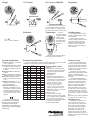
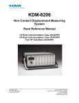
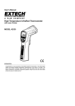
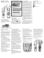
Digital CLAMP
Meters SC66 SC67
!
WARNINGS
!
Clean the exterior with clean dry
cloth. Do not use liquid.
Battery Replacement: When the
multimeter displays “
“ the battery
must be replaced. Disconnect and
unplug leads, turn meter off, and remove
the battery cover. Replace the battery
with a NEDA type 1604 9V battery.
General: Disconnect the test leads
before opening the case. Inspect the
test leads for damage to the insulation
or exposed metal. Replace if suspect.
Never ground yourself when taking
electrical measurements. Do not touch
exposed metal pipes, outlets, fixtures,
etc., which might be at ground potential.
Keep your body isolated from ground
by using dry clothing, rubber shoes,
rubber mats, or any approved insulating
material. When disconnecting from
a circuit, disconnect the “RED” lead
first, then the common lead. Work with
others. Use one hand for testing. Turn
off power to the circuit under test before
cutting, unsoldering, or breaking the
circuit. Keep your fingers behind the
finger guards on the probes. Do not
measure resistance when circuit is
powered. Do not apply more than rated
voltage between input and ground.
All Voltage Tests: All voltage ranges
will withstand up to 600VDC or 600VAC.
Do not apply more than 600VDC or
600VAC.
AC Tests: Disconnect the meter from
the circuit before turning any inductor
off, including motors, transformers, and
solenoids. High voltage transients can
damage the meter beyond repair. Do not
use during electrical storms.
Hi voltage indicator
Field OF calibration
DISCONNECT AND UNPLUG
TEST LEADS before opening case.
TEST NCV FUNCTION ON
KNOWN LIVE WIRE before using.
DO NOT APPLY VOLTAGE
greater than 30VAC or 60VDC to the
thermocouple or the jacks when the
rotary dial is on OF.
REMOVE THE THERMOCOUPLE
when taking voltage measurements.
DISCONNECT THE TEST LEADS
when taking temperature measurements.
DO NOT APPLY VOLTAGE TO
THE JACKS when the rotary dial is
on microamps. Even low voltages
can cause a current overload and
blow the fuse. Replace blown fuse to
regain function.
Maintenance
General description
Models SC66 and SC67 have
special features for the HVAC/R
service technician who wants to carry
one instrument.
For your safety...
Symbols used:
Caution, risk of electric shock
! Caution, refer to manual.
Ground
Double insulation
OPERATOR’S MANUAL
Non-contact voltage
(NCV)
With the NCV tab on the tip of the
clamp close to an AC voltage, press
the NCV button, the NCV LED will
light and the beeper will beep. The
closer you get to AC voltage, the
louder the beep. The NCV function is
sensitive enough to detect 24VAC on
thermostats.
Microamps DC
For measuring the flame diode
current in a heater control.
The clamp meter is protected by
a PTC resistor, not a fuse. When an
overload occurs on µADC, reset the
PTC by disconnecting from the circuit
for at least 30 seconds.
Capacitance
For motor-start and motor-run
capacitors. Disconnect the capacitor
from power first. Short the terminals
to discharge the capacitors.
Disconnect any resistors that might
be between the terminals of the
capacitor.
Auto power off
To extend the life of your battery,
the meter automatically turns off after
approximately 60 minutes.
In any VAC/VDC range when you
touch a voltage greater than 30V, the
beeper will beep and the red Hi-V LED
will blink. BE CAREFUL!
MAX hold for safety
Before measuring voltage, press
MAX button and keep your eyes on
your test point. Then when you’ve
disconnected, read the display.
Current measurements
The fixed jaw is longer than the
moveable jaw to make it easier to select
just one wire from a bundle. With the
jaws closed, separate one wire using
the long fixed jaw. Slide it to the corner
where the two jaws meet. Then open the
jaws to let it in. You can select the wire
without having to hold the jaws open.
Temperature
Plug any K-type thermocouple
directly into the meter to measure
temperature. Temperature measurement
will be accurate even in fast changing
environments because of excellent
temperature compensation. One
thermocouple is included. No adapter is
required.
Display oC or oF
Remove back of meter and locate
jumper on lower right corner of PCB
(marked OC). Place a jumper over the
pins to display oC.
For accuracies of ±1°F calibrate the
meter to a known temperature. A glass
of stabilized ice water is very close to
32°F and is usually very convenient.
1. Connect thermocouple.
2. Select the 200°F range.
3. Remove back case. Hold the battery
in place with a rubber band.
4. Stabilize a large cup of ice water.
5. Immerse the thermocouple probe and
let it stabilize.
6. Adjust VR3 (lower right corner of
PCB) to get close to 32°F then adjust
VR4(above VR3) to get within 0.1°F
of 32°F.
7. To calibrate in OC, close the jumper
that is below VR3.
VR4
VR3
Jumper
Using & storing test leads
Because the wire insulation is
silicone, you can use your test leads
in very cold weather and they will stay
flexible. They will also take a bump of
a soldering iron without melting.
Snap the probes into the back to
keep them out of the way.
Use the single test probe holder
on clamp to make voltage testing
easy.
For convenient lead storage, wrap
the leads as shown.
Voltage
AC Current
DC Current <200µADC
Capacitance
DISCHARGE
A PTC resistor, not a fuse, protects
your clamp meter. When an overload
occurs on µADC, do not apply current
for at least 30 seconds to reset the PTC.
Resistance
Temperature
V = IR
volts = current x resistance
Insure the
temperature being
measured is stable.
Maintain good
contact between
the thermocouple
and what’s being
measured.
CAPACITOR
Selecting ranges
For DC voltage, set the meter to
the VDC parameter instead of VAC
as shown above.
For all ranges and functions
choose a range just above the value
you expect. If display reads “OL”
(overload), select a higher range.
If display shows less than three
numbers, select a lower range for
better resolution.
Disconnect test leads from voltage
before plugging thermocouple in.
v37
General specifications
Indicators: Low battery. Overrange:
“OL” is displayed.
Environmental: Operating temperature 32°F to 122°F, storage 0°F
to 140°F with batteries removed,
RH<80%.
Measurement rate: 2.5 times/sec
nominal.
Battery: 9V NEDA 1604; 150 hours
typical with carbon zinc (installed).
Auto power off: Meter automatically turns off after approximately
1 hour.
Temperature coefficient: 0.1 X
(specified accuracy) per °F above
82°F and below 64°F.
Industry specifications: IEC/
EN61010-1, IEC/EN61010-2-32,
Cat III (600V for SC66 and SC67)
class 2 and pollution degree 2, in
accordance with IEC-664 indoor
use. UL listed to UL3111. C-Tick
certified.
This instrument complies with
the requirements of the following
European Community Directives:
89/336/EEC (Electromagnetic
Compatibility) and 73/23/EEC (Low
Voltage) as amended by 93/68/EEC
(CE Marking).
Functional specifications
Accuracy specifications @ 74°F±8°F, relative humidity less than 75%. Accuracy
specified as ±% of reading ± number of least significant digits.
Function Range
Accuracy
/resolution
SC66
3%+5 / 0.1 (1)
×
SC67
AAC
200
20
3%+5 / 0.01
×
VAC(2,3)
200
1.2%+3 / 0.1
×
×
600
2%+5 / 1
×
×
VDC(2)
20
0.5%+1 / 0.01
×
200
0.5%+1 / 0.1
µADC(4)
200
1%+1 / 0.1
×
×
°F (5)
200°F
1°F / 0.1
×
×
×
×
×
1000°F 1%+1.5°F / 1
MFD (6)
200
Hi-V (7)
Beep
& LED
NCV (8)
+24V
Ohms(9)
200
1%+3 / 0.1
200k
1%+3 / 0.1k
×
×
Continuity
(10)
Beep
&LED
Beep
&LED
MAX hold
(11)
×
×
Diode test
×
×
3%+5 / 0.1
×
×
×
×
×
×
×
×
Notes to chart on left:
50-60Hz
Input impedance is 560Kohms on
volts ranges, 10Mohm on millivolts
ranges. All ranges will withstand
600VAC/600VDC.
(3) 50Hz-500Hz.
(4) Protected by PTC (positive temperature coefficient) resistor. If an
overload occurs on microamps DC,
disconnect from circuit for 30 seconds so the PTC can reset.
(5) Accuracy 1OF (32OF to 120OF);
1%+1.5OF (-4OF to 750OF);
2%+4OF (-30OF to -4OF, 750OF to
1000OF); all withstand 30V max.
(6) Test frequency 34Hz at <3.5V. Will
withstand up to 500V.
(7) Turns on >30V.
(8) Senses 24VAC to 600VAC.
(9) 0.3VDC typical open circuit voltage.
(3V on 200ohm range). Withstands
up to 500V on any ohms range.
(10) Turns on <100 ohms within 100mS.
Will withstand up to 500V.
(11) Holds highest reading.
(1)
(2)
www.fieldpiece.com
Limited warranty
This meter is warranted against
defects in material or workmanship
for one years from date of purchase.
Fieldpiece will replace or repair the
defective unit, at its option, subject to
verification of the defect.
This warranty does not apply to
defects resulting from abuse, neglect,
accident, unauthorized repair,
alteration, or unreasonable use of the
instrument.
Any implied warranties arising
from the sale of a Fieldpiece product,
including but not limited to implied
warranties of merchantability and
fitness for a particular purpose, are
limited to the above. Fieldpiece
shall not be liable for loss of use of
the instrument or other incidental or
consequential damages, expenses,
or economic loss, or for any claim of
such damage, expenses, or economic
loss.
State laws vary. The above limitations
or exclusions may not apply to you.
Obtaining service
Call Fieldpiece Instruments for
one-price-fix-all warranty service
pricing. Send check or money order
for the amount quoted. Send the
meter freight prepaid to Fieldpiece
Instruments. Send proof of date
and location of purchase for inwarranty service. The meter will be
repaired or replaced, at the option of
Fieldpiece, and returned via least cost
transportation.