1
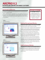
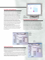
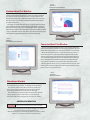
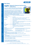
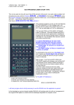
TEST, MEASUREMENT & SAFETY
Engineering Software
ARCPRO V.2
ELECTRICAL ARC HAZARD ASSESSMENT SOFTWARE
ARCPRO v.2 is a software program developed to calculate the thermal
parameters of electrical arcs. The program is designed to aid in the
selection of protective clothing by defining the arc hazard for workers
who may be accidentally exposed to electrical arcs. The user can then
specify clothing that will withstand the level of predicted arc hazards.
OSHA regulations have made it necessary for employers to
ensure that clothing worn by workers exposed to electrical arcs
must not contribute to the extent of an injury. OSHA requires
utilities and industries to show compliance with such regulations
if there is an accident.
ARCPRO v.2 is designed to provide the user with calculations including
heat exposure, total heat flux and heat energy on a surface at various
distances from an electric arc. The software is used to predict the
potential arc hazard in a particular work environment and thus it
can help in choosing the appropriate protective clothing. Beyond
selection of clothing, ARCPRO can be used to modify work practices
to remove staff from hazardous areas. The ARCPRO v.2 computer
program is based on a state-of-the-art electrical arc model.
Temperature-dependent gas properties, the electrode materials
and configuration are taken into account in the model.
Most of the calculation results are provided in numeric and
graphic forms on the screen and can be sent to a printer. Users
provide several input parameters describing the arc and then
simply click on menu items to run calculations and view results.
The typical input to the program includes arc current, arcing gap,
and distance from their working conditions. The typical output
from the computer program includes the total energy available,
the heat and heat flux at any location around the arc, an illustration
of the zone in which a particular fabric will ignite, radiated heat
flux, convected heat flux, second degree burn criteria and
waveforms of the arc current, arc voltage, and arc diameter.
HD ELECTRIC COMPANY
1475 LAKESIDE DRIVE • WAUKEGAN, ILLINOIS 60085 U.S.A.
P H O N E 8 4 7 . 4 7 3 . 4 9 8 0 • FA X 8 4 7 . 4 7 3 . 4 9 8 1 • w e b s i t e : w w w. H D E l e c t r i c C o m p a n y. c o m
ARCPRO V.2
ELECTRICAL ARC HAZARD ASSESSMENT SOFTWARE
Initial Screen and Menu Bar
ARCPRO v.2 starts out with a title screen that welcomes you to the program. After
you continue from the title page a menu bar appears. The menu bar is located at the
top of each ARCPRO v.2 window.
Selections from the menu are easily made using a mouse. The menu bar allows users
to save results of calculations, load previous cases, print graphics screens, perform heat
calculations, analyze clothing performance and view the results in all other windows.
The menu bar also has a “Help” section that offers comprehensive on-screen assistance
in using ARCPRO v.2.
ARCPRO v.2 Package
The ARCPRO v.2 software is
accompanied by a user manual,
a hardware security key, a user
license and limited warranty, and an
acknowledgment and registration
form. ARCPRO v.2 requires 2MB of
hard disk space and operates in
Windows 3.1 or greater.
FIGURE 1
ARCPRO v.2
Total Heat Flux Window
Total Heat Flux (and input) Window
FIGURE 2
ARCPRO v.2
Ignitable Clothing Window
The Total Heat Flux Window (Figure 1) is the main window in ARCPRO
v.2 and is used to input arc parameters, run a calculation, and view the
total heat flux results. The range of current is 0.2 to 100kA.
When calculations have been completed the Total Heat Flux Window
will appear as shown in Figure 1. Heat flux results are shown in the
results box, located under the Status Bar. The initial total heat flux
value that appears in the result box is for a specific distance from
the arc that was defined in the input. Arc Energy, Arc Voltage and
Maximum Heat Flux values correspond to the initial inputs.
The display on the bottom left of the screen is a graph of the heat
flux magnitude as it varies with radial distance away from the center
of the arc. Colors are associated with heat flux magnitude as defined
by the Heat Zone Legend in the center of the screen.
On the bottom right of the screen is a Heat Flux Contour chart.
This is a two-dimensional area graph with heat flux magnitude as
indicated by colored contour bands. The precise heat flux value at
any location in this space can be determined by moving the mouse
to the desired location and clicking the mouse button. In the upper
right hand corner of the chart is a position indicator that shows
the R (radial) and Z (vertical) coordinates and the heat flux at that
location, in the form Flux (R, Z) = value.
Cloth Performance Windows
The Cloth Performance Windows include the Ignitable Clothing
Window (Figure 2) and the Fire Retardant Clothing Window (Figure 3).
Both windows display the energy from the arc and allow the user
to compare this to the thresholds for fabrics. The Cloth Selected
box gives the name of the current database and a summary for
selected clothing.
Ignitable Clothing Window
The Ignitable Clothing Window displays heat energy (as
opposed to heat flux) at various distances from the arc as well
as the zone within which a particular article of clothing will
ignite under the input arc conditions. Heat energy results for
the particular input data are shown in the result box.
The display on the left side of the screen is a graph of the
magnitude of the heat as it varies with the radial distance
away from the center of the arc. The red zone indicates the
distances at which the heat is greater than the 50% ignition
threshold for the selected clothing. The magenta zone
indicates the distances at which the heat is greater than the
10% ignition threshold for the selected clothing. The dark
blue zone indicates the distances at which the heat is greater
than the 1% ignition threshold for the selected clothing. The
light blue zone indicates the distance at which the heat is
below the specified ignition threshold.
On the right side of the screen is a Heat Contour chart.
This is a two-dimensional area graph. The precise heat
magnitude at any location in this space can be determined
by moving the mouse to a desired location and clicking
the mouse button.
FIGURE 3
ARCPRO v.2
Fire Retardant
Clothing Window
Fire Retardant Clothing Window
The Fire Retardant Clothing Window (Figure 3) allows the user
to view the heat energy (Time Integral of Heat Flux) at various
distances from the arc and to assess the zones of arc thermal
protection for Fire Retardant Clothing selected from a database.
The heat energy results appear in the Results Box and in the two
graphs. The Heat Threshold legends for the two graphs indicate
the zones where heat exceeds the following thresholds: the Arc
Thermal Protective Value (ATPV), the ATPV 95%, and the ATPV 95%
points. The ATPV for fire retardant clothing is the minimum incident
thermal energy that causes the onset of a second-degree burn.
FIGURE 4
ARCPRO v.2
Ignitable
Clothing
Database
FIGURE 5
ARCPRO v.2
Fire Retardant Clothing Database
Clothing Databases
Clothing databases are provided for both Ignitable and Fire Retardant Clothing. For each category there are two types of databases; a non-editable internal
database and an open user database. The clothing databases describe clothing
parameters. The parameters represented are: manufacturer, material, weight,
construction, coating and color.
For Ignitable Clothing, the parameters include Thresholds of Ignition (Figure
4). For Fire Retardant Clothing, the parameters include the Arc Thermal Protective Values (ATPV) and the Heat Attenuation Factors (HAF) (Figure 5). The Ignition
Threshold and the Arc Thermal Protective Values are based on arc testing of
clothing according to standard testing procedures.
FIGURE 6
ARCPRO v.2
Radiated Heat Flux Window
Radiated Heat Flux Window
The Radiated Heat Flux Window (Figure 6) shows the component
of total heat flux that is transferred to a surface by thermal radiation,
the major mechanism of heat transport in arcing situations. Arc
Energy, Radiated Energy and Radiated Heat Flux for the case input
data are shown in the result box. Maximum Radiated Heat Flux is
also shown in this box.
The display on the left side of the screen is a graph of the magnitude
of the radiated heat flux as it varies with the radial distance away from
the center of the arc. Colors are associated with heat flux magnitude as
defined by the legend in the center of the screen. On the right side of the
screen is a Heat Flux Contour chart. This is a two-dimensional area graph
with heat flux magnitude indicated by colored contour bands.
FIGURE 7
ARCPRO v.2
Convected Heat Flux Window
Convected Heat Flux Window
The Convected Heat Flux Window (Figure 7) shows the component
of total heat flux that is transferred to a surface by convection. Arc and
Convection Energy for the case input data are shown in the result box.
On the left side of the screeen is a Heat Flux Contour Chart. This is a
two-dimensional area graph with heat flux magnitude indicated by
colored contour bands. Convection is time dependent. The left-hand
chart shows the magnitude of convective heat flux at the instant that
the arc extinguishes. The heat flux magnitude associated with each
color contour is specified in the legend in the center of the screen.
On the right side of the screen is another Heat Flux Contour chart
showing the maximum magnitude of convective heat flux at every
point in space at any point in time.
FIGURE 8
ARCPRO v.2
Waveforms Window
Waveforms Window
The Waveforms Window (Figure 8) shows the time varying
waveforms for the arc current, arc voltage and arc diameter.
The numeric values to the left on the screen are the root
mean square (rms) quantities associated with the current
and voltage, and the mean value of the arc diameter.
The calculated arc voltage includes the anode and cathode
voltage drops that have a dependency on the electrode
materials as well as the voltage drop across the arc column.
ORDERING INFORMATION
ARCPRO2.01
Electrical Arc Hazard Assessment Software
Upgrades from previous ArcPro versions are available, contact HDE
* Due to a policy of continuous improvement, HD Electric Company reserves the right to
change product designs and specifications without notice.
HD Electric Company products are available through HDE sales representatives worldwide.
Printed in U.S.A. © HD Electric Company 2013 • Bulletin No. ARC-300b