1
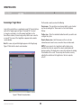
OmniViewIP*
5216K/5232K
User Manual
PM00020ea - F1DP2XXGea
*OmniView is a registered trademark of Belkin International, Inc.
Table of Contents
Table of Contents
sections
1
2
3
4
5
6
1 Introduction . . . . . . . . . . . . . . . . . . . . . . . . . . . . . . . . . . . . . . . . . . . 1
3 Web Interface . . . . . . . . . . . . . . . . . . . . . . . . . . . . . . . . . . . . . . . . . 15
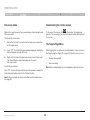
Key Features . . . . . . . . . . . . . . . . . . . . . . . . . . . . . . . . . . . . . . . . . . . . . .
System Contents . . . . . . . . . . . . . . . . . . . . . . . . . . . . . . . . . . . . . . . . . .
System Requirements . . . . . . . . . . . . . . . . . . . . . . . . . . . . . . . . . . . . . .
Terminology . . . . . . . . . . . . . . . . . . . . . . . . . . . . . . . . . . . . . . . . . . . . . .
Unit Display Diagrams . . . . . . . . . . . . . . . . . . . . . . . . . . . . . . . . . . . . . .
LED and button table . . . . . . . . . . . . . . . . . . . . . . . . . . . . . . . . . . . . . . .
Connector table . . . . . . . . . . . . . . . . . . . . . . . . . . . . . . . . . . . . . . . . . . .
Logging In to the Web Interface . . . . . . . . . . . . . . . . . . . . . . . . . . . . .
SSL certificate notes . . . . . . . . . . . . . . . . . . . . . . . . . . . . . . . . . . . . . .
Logging in . . . . . . . . . . . . . . . . . . . . . . . . . . . . . . . . . . . . . . . . . . . . . . .
Connecting to a target server . . . . . . . . . . . . . . . . . . . . . . . . . . . . . . .
Configuring the System . . . . . . . . . . . . . . . . . . . . . . . . . . . . . . . . . . . .
Network > Configuration . . . . . . . . . . . . . . . . . . . . . . . . . . . . . . . . . . .
LAN . . . . . . . . . . . . . . . . . . . . . . . . . . . . . . . . . . . . . . . . . . . . . . . . .
OmniView IP Central Access Appliance 5000HQ . . . . . . . . . . . . . . . .
Administration > User Settings . . . . . . . . . . . . . . . . . . . . . . . . . . . . . .
Adding a user . . . . . . . . . . . . . . . . . . . . . . . . . . . . . . . . . . . . . . . . . . . .
Editing a user . . . . . . . . . . . . . . . . . . . . . . . . . . . . . . . . . . . . . . . . . . . .
Deleting a user . . . . . . . . . . . . . . . . . . . . . . . . . . . . . . . . . . . . . . . . . . .
Blocking a user . . . . . . . . . . . . . . . . . . . . . . . . . . . . . . . . . . . . . . . . . . .
Administration > Server Name Edit . . . . . . . . . . . . . . . . . . . . . . . . . . .
Administration > Serial Settings . . . . . . . . . . . . . . . . . . . . . . . . . . . . .
Administration > Server Access List . . . . . . . . . . . . . . . . . . . . . . . . . .
Security > Settings . . . . . . . . . . . . . . . . . . . . . . . . . . . . . . . . . . . . . . . .
Security > SSL Certificate . . . . . . . . . . . . . . . . . . . . . . . . . . . . . . . . . .
Maintenance > Switch Upgrade . . . . . . . . . . . . . . . . . . . . . . . . . . . . .
Maintenance > SIM Upgrade . . . . . . . . . . . . . . . . . . . . . . . . . . . . . . . .
Restore Factory Settings . . . . . . . . . . . . . . . . . . . . . . . . . . . . . . . . . . .
Set Time and Date . . . . . . . . . . . . . . . . . . . . . . . . . . . . . . . . . . . . . . . .
Back Up and Restore . . . . . . . . . . . . . . . . . . . . . . . . . . . . . . . . . . . . . .
Saving Changes and Logging Out . . . . . . . . . . . . . . . . . . . . . . . . . . . .
2
4
4
5
6
6
6
2 Installation . . . . . . . . . . . . . . . . . . . . . . . . . . . . . . . . . . . . . . . . . . . . 7
Pre-Installation Guidelines . . . . . . . . . . . . . . . . . . . . . . . . . . . . . . . . . . . 7
Avoiding general rack-mounting problems . . . . . . . . . . . . . . . . . . . . . . 7
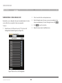
Rack-mounting the SMB 216 IP KVM Switch . . . . . . . . . . . . . . . . . . . . 8
Connecting the System . . . . . . . . . . . . . . . . . . . . . . . . . . . . . . . . . . . . . 9
The Server Interface Modules (SIMs) . . . . . . . . . . . . . . . . . . . . . . . . . 10
Connecting a PS/2 SIM . . . . . . . . . . . . . . . . . . . . . . . . . . . . . . . . . . . . 11
Connecting a USB SIM . . . . . . . . . . . . . . . . . . . . . . . . . . . . . . . . . . . . 11
Connecting to the network . . . . . . . . . . . . . . . . . . . . . . . . . . . . . . . . . 12
Connecting the CAT5 cables . . . . . . . . . . . . . . . . . . . . . . . . . . . . . . . . 12
Connecting the local console . . . . . . . . . . . . . . . . . . . . . . . . . . . . . . . 12
Connecting the power supply . . . . . . . . . . . . . . . . . . . . . . . . . . . . . . . 12
Setting the IP Address . . . . . . . . . . . . . . . . . . . . . . . . . . . . . . . . . . . . . 13
OmniViewIP 5216K/5232K
i
15
15
16
17
17
17
18
18
19
20
20
20
20
21
21
22
23
24
24
25
25
26
26
27
Table of Contents
Table of Contents
sections
1
2
3
4
5
6
4 Remote Access . . . . . . . . . . . . . . . . . . . . . . . . . . . . . . . . . . . . . . . 28
5Local Access . . . . . . . . . . . . . . . . . . . . . . . . . . . . . . . . . . . . . . . . . 44
Accessing a Target Server . . . . . . . . . . . . . . . . . . . . . . . . . . . . . . . . . .
The toolbar . . . . . . . . . . . . . . . . . . . . . . . . . . . . . . . . . . . . . . . . . . . . . .
Switching to a different server . . . . . . . . . . . . . . . . . . . . . . . . . . . . . . .
Changing the performance settings . . . . . . . . . . . . . . . . . . . . . . . . . .
Adjusting the video settings . . . . . . . . . . . . . . . . . . . . . . . . . . . . . . . .
Refresh . . . . . . . . . . . . . . . . . . . . . . . . . . . . . . . . . . . . . . . . . . . . . . . . .
Manual video adjust . . . . . . . . . . . . . . . . . . . . . . . . . . . . . . . . . . . . . . .
Auto video adjust . . . . . . . . . . . . . . . . . . . . . . . . . . . . . . . . . . . . . . . . .
Keyboard key sequences . . . . . . . . . . . . . . . . . . . . . . . . . . . . . . . . . . .
Synchronizing mouse pointers . . . . . . . . . . . . . . . . . . . . . . . . . . . . . .
Aligning the mice pointers . . . . . . . . . . . . . . . . . . . . . . . . . . . . . . . . . .
Manual settings . . . . . . . . . . . . . . . . . . . . . . . . . . . . . . . . . . . . . . . . . .
Calibrating mice pointers . . . . . . . . . . . . . . . . . . . . . . . . . . . . . . . . . . .
Adjustments in general . . . . . . . . . . . . . . . . . . . . . . . . . . . . . . . . . . . .
Globe icon menu features . . . . . . . . . . . . . . . . . . . . . . . . . . . . . . . . . .
Virtual media . . . . . . . . . . . . . . . . . . . . . . . . . . . . . . . . . . . . . . . . . . . . .
Full-screen mode . . . . . . . . . . . . . . . . . . . . . . . . . . . . . . . . . . . . . . . . .
Disconnecting the remote session . . . . . . . . . . . . . . . . . . . . . . . . . . .
The Targets Page Menu . . . . . . . . . . . . . . . . . . . . . . . . . . . . . . . . . . . .
Changing the password . . . . . . . . . . . . . . . . . . . . . . . . . . . . . . . . . . . .
Event log . . . . . . . . . . . . . . . . . . . . . . . . . . . . . . . . . . . . . . . . . . . . . . . .
Downloading the log . . . . . . . . . . . . . . . . . . . . . . . . . . . . . . . . . . . . . .
Clearing the log . . . . . . . . . . . . . . . . . . . . . . . . . . . . . . . . . . . . . . . . . .
The OSD . . . . . . . . . . . . . . . . . . . . . . . . . . . . . . . . . . . . . . . . . . . . . . . .
Navigating the OSD main window . . . . . . . . . . . . . . . . . . . . . . . . . . . .
Selecting a computer . . . . . . . . . . . . . . . . . . . . . . . . . . . . . . . . . . . . . .
Moving the confirmation label – F1 . . . . . . . . . . . . . . . . . . . . . . . . . . .
Tuning – F5 . . . . . . . . . . . . . . . . . . . . . . . . . . . . . . . . . . . . . . . . . . . . . .
The Settings window – F2 . . . . . . . . . . . . . . . . . . . . . . . . . . . . . . . . . .
DDC – F10 . . . . . . . . . . . . . . . . . . . . . . . . . . . . . . . . . . . . . . . . . . . . . . .
Saving changes to the settings . . . . . . . . . . . . . . . . . . . . . . . . . . . . . .
OmniViewIP 5216K/5232K
28
29
29
29
30
30
31
32
32
34
34
36
38
38
39
40
42
42
42
43
43
43
43
44
44
44
45
45
46
47
47
6Additional Information . . . . . . . . . . . . . . . . . . . . . . . . . . . . . . . . . 48
Technical Specifications . . . . . . . . . . . . . . . . . . . . . . . . . . . . . . . . . . .
Video Resolution and Refresh Rates . . . . . . . . . . . . . . . . . . . . . . . . . .
Safety 50
User Manual Feedback . . . . . . . . . . . . . . . . . . . . . . . . . . . . . . . . . . . .
Product Registration . . . . . . . . . . . . . . . . . . . . . . . . . . . . . . . . . . . . . .
Information . . . . . . . . . . . . . . . . . . . . . . . . . . . . . . . . . . . . . . . . . . . . . .
ii
48
49
50
50
51
Introduction
Table of Contents
sections
1
2
3
4
5
6
Congratulations and thank you for purchasing the Belkin OmniView IP 5216K/5232K Switch with the latest in IP KVM technology.
This Switch provides a simple, quick, remote server management solution for medium to large-size businesses. The Switch allows
two remote digital users and one local analog user to access and control your servers over the Internet via a standard web browser.
Combine the Switch with the Belkin Central Access Appliance 5000HQ to address the management and administration needs of
more users accessing more servers across geographical locations.
The innovative technology in the OmniView IP 5216K/5232K Switch combines hardware and software technology to deliver highperformance remote access, and enables you to troubleshoot servers faster and more efficiently, reducing server downtime and
service costs in mission-critical environments.
Belkin’s distinctive technology provides IT professionals:
•
Immediate video synchronization, allowing access through the entire boot sequence, when troubleshooting is most critical. •
Immediate video display and keyboard output to intercept systems at their earliest status upon power-up or reboot.
•
Instantaneous access between multiple sessions over IP. Users experience immediate access when switching between attached systems,
eliminating the delay when managing time-sensitive system access and repair.
This User Manual provides all the details you’ll need to install and operate your new OmniView IP 5216K/5232K Switch, in addition
to expert troubleshooting advice—in the unlikely event of a problem. For quick and easy installation, please refer to the Quick
Installation Guide included in your packaging.
We appreciate your business and are confident that you will soon see for yourself why over 1 million Belkin OmniView KVM
products are in use worldwide.
OmniViewIP 5216K/5232K
1
Introduction
Table of Contents
sections
1
2
3
4
5
6
Key Features
High-Performance Remote Access
•
Access, switch, view, and control faster than before
•
Switch from one remote server to another instantly
•
Quicker performance over the Internet and congested networks
•
View all the information displayed during the post and boot process
Web-Browser Based
The Switch allows you to access your KVM switch and all connected servers from any computer connected to the LAN, WAN, or
Internet using Firefox® or Microsoft Internet Explorer ®.
Out of Band—BIOS-Level Access
The Switch allows you to remotely access the basic input/output system (BIOS) of your servers to make changes and perform
reboots, regardless of network connectivity or server condition.
User-Friendly Interface
The web-based interface allows you to set up and change the Switch’s functions quickly and easily through your web browser,
without having to install additional software onto your servers.
Remote Serial Access
The Switch provides support for up to two serial devices, such as a managed power distribution unit (PDU), so you can remotely
perform hard reboots of your servers.
OmniViewIP 5216K/5232K
2
Introduction
Table of Contents
sections
1
2
3
4
5
6
Virtual-Media Technology
The Switch provides virtual-media support for up to two servers. This allows the remote user to copy files from a USB or CD-ROM
drive to a target server that may be anywhere in the world. Or boot a remote server from a local USB or CD-ROM drive.
Enhanced Security
The IP device provides 128-bit Secure Sockets Layer (SSL) authentication and password protection to prevent unauthorized access
to your servers and protect data transferred over the Internet. The data communication is also protected with AES
256-bit encryption.
Scalable Centralized Management
Additional Switches can be added as your data center grows and the entire inventory can be managed under the Belkin Central
Access Appliance 5000HQ. This is ideal for corporations operating servers at multiple sites such as testing labs, campuses, branch
offices, and multi-floor facilities.
Video Resolution
The Switch supports video resolutions of up to 1600x1200@75Hz for both local and remote consoles.
Flash-Upgradeable
Flash upgrades allow you to obtain the latest firmware updates for your Switch. These firmware updates ensure that the Switch is
compatible with the latest devices.
OmniViewIP 5216K/5232K
3
Introduction
Table of Contents
sections
1
2
3
System Contents
•
1 OmniView IP 5216K/5232K Switch
•
1 AC Power Cable
•
1 Serial-to-RJ45 Interface Cable
•
1x User Manual CD
•
1 Quick Start Guide
•
1 Set Rack-Mount Brackets and Screws
•
Schuko and UK power Connector
4
5
Servers
•
PS/2 and USB computers/servers
•
VGA, SVGA, or XGA monitors
Keyboards and Mice
•
USB-compatible
Monitors
•
CRT and LCD (with VGA, SVGA, or XGA monitors)
Remote-Client Browser
The Switch may be accessed remotely over a TCP/IP connection from
computers using the following web browsers and OS platforms:
System Requirements
Host Computer Operating-System (OS) Platforms
The Switch is compatible with CPUs running on, but not limited to, the
following OS platforms:
Windows
•
Windows® 2000, XP, Server 2003 and 2008, Vista®
• Firefox 3.0 and above**
•
Microsoft DOS 5.x and above
Linux (major distributions only)
•
Red Hat® Linux® 8.x and above
• Firefox 3.0 and above**
•
Sun™*
•
Novell 5.x
**Firefox support may require a firmware upgrade. Visit
www.belkin.com/support for more information.
•
Sun Solaris™ 8.x and above*
• Microsoft Internet Explorer 6.0 and above with ActiveX® support
®
®
Server Interface Modules
Connecting the Switch to a server requires a custom Belkin OmniView
SMB Server Interface Module and a standard CAT5 patch cable.
*USB server interface module required
OmniViewIP 5216K/5232K
6
4
Introduction
Table of Contents
sections
1
2
3
5
Terminology
OmniView sMb server Interface Modules:
F1DP101AeaAP (PS/2 style)
F1DP101AeaAU (USB style)
F1DP101AeaAS (Legacy Sun, miniDIN8 style)
F1DP101AeaAP-8P (PS/2 style, 8-pack)
F1DP101AeaAU-8P (USB style, 8-pack)
Below are some terms and their meanings used in this guide.
CAT5 Cables
Belkin highly recommends you use Belkin Category 5e, FastCAT™ 5e,
or Category 6 Patch Cables for your OmniView IP 5216K/5232K Switch
to help ensure the superior performance of your video. These Cables
offer the highest quality possible to ensure optimal data and video
transmission.
Belkin UTP Patch Cables:
A3L791-XX-YYY (CAT5e)
A3L850-XX-YYY (FastCAT 5e)
A3L980-XX-YYY (CAT6)
Note: Use CAT6 solid cables for optimal video at longer lengths.
Product codes and availability may vary.
OmniViewIP 5216K/5232K
4
5
Term
Meaning
Target server
The computers/servers that are accessed
remotely via the Switch.
Client computer
The PC running a remote session.
Remote session
The process of remotely accessing and
controlling target servers connected to the
Switch from a user workstation.
6
Introduction
Digital
Table of Contents
sections
1
2
3
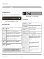
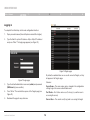
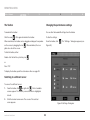
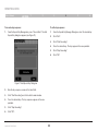
Unit Display Diagrams
4
J<I@8C(
5
6
J
<
I
)
CF:8CLJ<I
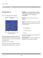
Figure
1 illustrates the front panel of the OmniView IP 5232K Switch.
Digital
GFN<I
(''$)+'M8:,'&-'?q
MD(
MD)
Figure 2 OmniView IP 5232K Switch – rear view
Connector table
Figure 1 OmniView IP 5232K Switch – front view
J<I@8C(
J
<
I
)
Connector
LED and button table
Function
CF:8CLJ<I
GFN<I
(''$)+'M8:,'&-'?q
LED
MD(
Function
Solid: Server is connected to and powered on
Port
Local Console
Connect a keyboard, video, and mouse to
operate the Switch locally.
Serial 1
Connect any serial device.
Serial 2
Connect any serial device.
Analog
MD)
Fast Blink: When a port is being accessed remotely
LAN
Connect to 10/100Mb Ethernet. Yellow LED
illuminates when connected to a LAN. Green
LED illuminates when a remote session is
in progress.
Server Ports
Connect to servers via SIMs (Server
Interface Modules).
VM1
Connect to server on server port 1 via
USB cable.
VM2
Connect to server on server port 2 via
USB cable.
Lj\i(
Analog
Slow Blink: When a port is being accessed locally
Ready
Solid Green: When unit is available for use
Link
Blinking Green: Unit is connected to the network
Power
Power Indicator
Lj\i(
GFN<I
(''$)+'M8:,'&-'?q
Lj\i)
GFN<I
(''$)+'M8:,'&-'?q
Note: The port LEDs flash in series during boot up and during
system upgrades. Allow approximately 45 seconds for boot up.
OmniViewIP 5216K/5232K
6
Lj\i)
INSTALLATION
Table of Contents
sections
1
2
3
Pre-Installation Guidelines
•
Place cables away from fluorescent lights, air conditioners, and
machines that are likely to generate electrical noise.
•
Place the Switch on a flat, clean, and dry surface.
•
The Switch is not intended for connection to exposed
outdoor lines.
•
Ensure that the maximum distance between each computer and
the Switch does not exceed 100 ft. for SIMs.
5
6
Mechanical loading
Mount the equipment in the rack in such a way that a hazardous
condition is not achieved due to uneven mechanical loading.
Circuit overloading
When connecting the equipment to the supply circuit, consider the
effect that overloading of circuits might have on over-current protection
and supply wiring.
Reliable electrical grounding of rack-mounted equipment should be
maintained. Provide attention to supply connections other than direct
connections to the branch circuit (e.g., use of power strips).
Avoiding general rack-mounting problems
Elevated operating ambient temperature
The operating ambient temperature of the rack environment may be
greater than the room ambient when installing into a closed or multiunit
rack assembly. Install the equipment in an environment compatible with
the maximum rated ambient temperature.
Reduced airflow
Install the equipment in a rack in such a way that the amount of airflow
required for safe operation is not compromised. Leave a gap of at least
5cm/2 inches on each side of the Switch.
OmniViewIP 5216K/5232K
4
7
INSTALLATION
Table of Contents
sections
1
2
3
Rack-mounting the SMB IP KVM Switch
5
6
Place the brackets toward the front of the unit so that the unit can be
mounted front facing; or place the brackets toward the rear of the unit
so that it can be mounted rear facing on the back of a rack. Figure 4
illustrates the bracket connected for rear facing. Screw the bracket to
the Switch using the screws provided.
Rack-mount the Switch using the supplied rack-mount kit. The brackets
can be placed in two possible positions (see Figure 3).
Figure 3 Bracket positions
OmniViewIP 5216K/5232K
4
Figure 4 Bracket connected
8
INSTALLATION
Table of Contents
sections
1
2
3
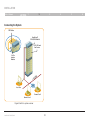
Connecting the System
CAT5 Cables
OmniView IP
5216K/5232K Switch
PS/2, USB, and
Sun Servers
Server
Interface
Modules
N
/WA
LAN
TCP/IP
Local User
Remote User 1
Remote User 2
Figure 5 Switch’s system overview
OmniViewIP 5216K/5232K
9
4
5
6
INSTALLATION
Table of Contents
sections
1
2
3
4
5
6
The Server Interface Modules (SIMs)
Each computer/server is directly connected to the Switch via the appropriate SIM using CAT5 cables in a star configuration. No external power is
needed at the remote SIMs. The SIMs draw their power from the computer’s keyboard port (PS/2 SIM) or from the USB port (USB SIM). The figures
below illustrate the SIM PS/2 and USB.
Figure 6 USB SIM2 (part no. F1DP101A-AU)
OmniViewIP 5216K/5232K
Figure 7 PS/2 SIM (part no. F1DP101A-AP)
10
INSTALLATION
Table of Contents
sections
1
2
3
Connecting a PS/2 SIM
Power down the server
2.
Connect the mouse connector to the computer’s mouse port.
3.
Connect the keyboard connector to the computer’s keyboard port.
4.
Connect the video connector to the computer’s VGA port.
5.
6
The USB SIM supports Windows 2000 and later, Sun, SGI, and all
modern Linux distributions. The connections for USB SIM are exactly
the same. Figure 9 illustrates the USB SIM and its connections.
To connect the USB SIM:
Power on the server.
1.
Connect the video connector to the server’s VGA port.
2.
Connect the USB connector to the server’s USB port.
SIM PS/2
SIM USB
Figure 8 PS/2 SIM connections
OmniViewIP 5216K/5232K
5
Connecting a USB SIM
Figure 8 illustrates the PS/2 SIM connections.
1.
4
Figure 9 USB SIM
11
INSTALLATION
Table of Contents
sections
1
2
3
4
5
6
Connecting to the network
Connecting the power supply
Connect the network cable to the LAN port of the Switch. This must be
done before powering on the Switch.
1.
Using the power cord provided, connect the Switch to a socket
outlet with a grounding connection. Only use the power cord
supplied with the unit.
Connecting the CAT5 cables
2.
Power on the Switch. Allow approximately 45 seconds for boot up.
1.
Connect one connector to the SIM’s RJ45 port.
2.
Connect the other connector to an available server port on
the Switch.
3.
Follow the steps above for each computer.
Connecting the local console
To operate the system locally, connect a local console to the Switch:
1.
Connect the monitor’s cable to the Switch’s console monitor port.
2.
Connect the keyboard’s cable to the Switch‘s console
keyboard port.
3.
Connect the mouse’s connector to the Switch’s console
mouse port.
OmniViewIP 5216K/5232K
12
INSTALLATION
Table of Contents
sections
1
2
3
Setting the IP Address
2.
4
5
6
Press “F2”. The Settings window appears (see Figure 11).
By default, the Switch boots with an automatically assigned IP address
from a DHCP (Dynamic Host Configuration Protocol) server on the
network. The DHCP server provides a valid IP address, gateway
address, and subnet mask.
You can identify the IP address from the OSD at the local position. You
can set the IP address locally via the OSD where there is no DHCP
server as follows:
1.
From the local keyboard, press “Scroll Lock”. The OSD Main
window appears (see Figure 10).
Figure 11 Settings window
In the Settings window, navigate downward using the Tab key. At the
bottom of the window, press “Tab” to go to the top of the window.
Change settings by typing in the selected area or by pressing the space
bar—whichever is relevant.
Figure 10 OSD Main window
OmniViewIP 5216K/5232K
13
INSTALLATION
Table of Contents
sections
1
2
3
Changing the network parameters
Enable DHCP – When a DHCP server is active on the same network to
which the Switch is connected, DHCP provides automatic IP assignment.
When DHCP is disabled (Recommended) – You can assign a fixed IP
address to the Switch.
Consult your network administrator regarding the use of the DHCP.
When DHCP is disabled, enter the IP Address, Subnet Mask, and
Gateway as given by your network administrator.
Once the IP address is satisfactory, log in to the web interface to
complete the configuration, as explained in the next section.
(Network parameters can also be changed from the remote GUI as
explained on page 17).
OmniViewIP 5216K/5232K
14
4
5
6
WEB INTERFACE
Table of Contents
sections
1
2
3
4
5
6
Logging In to the Web Interface
SSL certificate notes
Client computer operating system. Windows 2000 or higher, with
Internet Explorer 6.0 or later version. 128-bit encryption support is
required.
When first connecting, two browser security warnings appear. Click
“Yes” to proceed.
The first warning disappears upon the first Switch client installation,
when Belkin’s root certificate is installed.
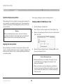
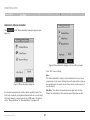
Windows Vista Note! To log in to the web configuration interface with
Windows Vista, run Internet Explorer as “administrator.” To do this,
right-click the Internet Explorer icon on the task bar and select “Run” as
“administrator.” See figure below.
On first connection, install the Belkin certificate and ActiveX control. You
must be logged in as an administrator on your computer to install the
ActiveX control. Once the ActiveX control is installed, all types of users
can log in.
Figure 12 Select Run as administrator
OmniViewIP 5216K/5232K
15
WEB INTERFACE
Table of Contents
sections
1
2
3
4
5
6
Logging in
To complete the initial setup via the web configuration interface:
1.
Open your web browser (Internet Explorer version 6.0 or higher).
2.
Type the Switch’s system IP address—http or https://IP address/ and press “Enter”. The login page appears (see Figure 13).
Figure 14 Targets page
By default, an administrator can access all connected Targets, so they
all appear on the Targets page.
Figure 13 Login page
Columns:
3.
Type the default administrator user name (admin) and password
(SMBremote) (case-sensitive).
4.
Press “Enter”. The web interface opens at the Targets page (see
Figure 14).
Port Status – Port status can be on, off, or busy (i.e., another user is
accessing the server).
5.
Bookmark the page for easy reference.
Current User – The current user (if any) who is accessing the target.
OmniViewIP 5216K/5232K
Server Name – The server name can be changed in the configuration
settings to give the server an identifiable name.
16
WEB INTERFACE
Table of Contents
sections
1
2
3
4
5
6
Connecting to a target server
Network > Configuration
To connect to a target, click the desired target in the Server Name
column. The screen of the target appears inside the remote console
window. The “Accessing a Target Server” section on page 28 explains
how to conduct a remote session. The following sections first explain
how to configure the system.
Consult your network administrator for the network settings if necessary.
Device Name – Type a name for the Switch.
TCP Ports – Choose any three TCP ports between ports 800 to 65535.
When the Switch is a standalone system, the ports do not have to be
consecutive. (The port numbers can be changed from Central Access
Appliance, if needed.)
Configuring the System
Configuring the system includes setting network parameters, user and
security settings, and maintenance.
Notes
The firewall or router security access list must enable inbound
communication through the selected TCP ports for the Switch’s
IP address.
From the menu, click “Configuration”. The “Network > Configuration”
page, including the Configuration menu, appears:
For client computer access from a secured LAN, the selected ports
should be open for outbound communication.
Figure 15 Network > Configuration page
OmniViewIP 5216K/5232K
17
WEB INTERFACE
Table of Contents
sections
1
2
3
LAN
5
6
OmniView IP Central Access Appliance 5000HQ
Under LAN in Figure 14, is the following:
OmniView IP 5000HQ is a centralized, IP-based system for secure
control of servers and network devices, power, and user administration
in the datacenter environment. The 5000HQ combines out-of-band,
KVM-via-IP access with modern IT standards and requirements. It is the
most comprehensive remote server maintenance solution available in
the market today.
Enable DHCP – When a DHCP server is active on the same network
to which the Switch is connected, DHCP provides automatic IP
assignment.
When DHCP is disabled (Recommended) – You can assign a fixed IP
address to Switch.
Enable OmniView IP 5000HQ – Check this option to allow the Switch
to be remotely managed by Central Manager Appliance 5000HQ.
Consult your network administrator regarding the use of the DHCP.
When DHCP is disabled, enter the IP Address, Subnet Mask, and
Default Gateway for LAN, as given by your network administrator.
These parameters can be configured locally from the OSD as explained
on page 14.
OmniViewIP 5216K/5232K
4
Manager Auto Discovery – When checked, 5000HQ automatically
detects the Switch if it resides on the same network segment.
Manager IP – If the Switch resides on a different segment, type the
static IP address of the 5000HQ management appliance. (We advise
typing the static IP address of the 5000HQ management appliance even
if the Switch resides on the same network segment as the 5000HQ
management appliance.)
18
WEB INTERFACE
Table of Contents
sections
1
2
3
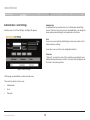
Administration > User Settings
4
5
6
Administrator
An administrator has unrestricted access to all windows and settings
and can “take over” any active session. An administrator can change the
name and password and target server permissions of all users.
From the menu, click “User Settings” and Figure 16 appears.
User
A user can access/control permitted target servers, but cannot use the
advanced mouse settings.
A user has no access to the web-configuration interface.
View only
“View only” can view the screen of the currently accessed target server
without keyboard and mouse control. A “view only” indicator appears on
the viewer’s local mouse pointer.
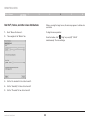
Figure 16 User Settings
On this page, an administrator creates and edits users.
There are three levels of user access:
•
Administrator
•
User
•
View only
OmniViewIP 5216K/5232K
19
WEB INTERFACE
Table of Contents
sections
1
2
3
4
5
6
Adding a user
Editing a user
To add a user:
To edit a user:
1.
1.
Select the user from the user drop-down menu.
2.
You can now change all the parameters—user name, permission,
password, and blocking status (see the “Blocking a user” section).
Click
Click
and type a name and a password. The password
must be at least six characters (letters or numbers), and must not
include the user name, even if other characters are added.
Note! The following “special” characters: &, <, >, ”, {, and } cannot
be used for either the user name or password.
3.
Depending on the security level chosen, the user name and
password parameters are different. See the “Security > Settings”
section on page 23.
Deleting a user
2.
Select the permission type from the “Permission” box.
To delete a user:
3.
Click
and the user will appear in the list of users. The
Permission column shows the user level (Administrator, User, and
View Only). The Status column shows whether the user is blocked
or unblocked (explained in the “Blocking a user” section).
1.
Select the user from the list.
2.
Click
.
3.
Click
to save any changes.
. The changes are saved.
Blocking a user
An alternative to deleting a user entry completely is blocking a user.
This means that the user’s name and password is stored, but the user is
unable to access the system. Check “Block” to block a user, and then
click
to save any changes. Uncheck “Block” and click
to
allow the user access.
OmniViewIP 5216K/5232K
20
WEB INTERFACE
Table of Contents
sections
1
2
3
Administration > Server Name Edit
2.
Give the servers connected to the Switch unique names, so that users
accessing the system can identify the servers easily.
To do so:
1.
4
5
6
In the “Server Name” section, change the name of the connected
servers by selecting the server name and typing a new name. Click
to save changes.
Administration > Serial Settings
From the menu, click “Server Name Edit”. The Switch Configuration
window appears (see Figure 17).
Where you have a serial device connected to the system, you must
configure the serial (RS232) settings.
To do so:
From the menu, click “Serial Settings”. The Serial Settings page will
appear (see Figure 18).
Figure 18 Serial Settings
For each serial device connected, type a device name and choose the
correct device parameters.
Figure 17 Switch Configuration
OmniViewIP 5216K/5232K
21
WEB INTERFACE
Table of Contents
sections
1
2
3
Administration > Server Access List
2.
3.
By default, access is allowed to all servers for administrators. For other
users, define the access rights of each user separately.
4
5
Select a user from the user drop-down menu.
Check the target servers the user can access (according to his or
her access permissions). To select all target servers, click
.
To do so:
4.
Click
1.
5.
Repeat the steps above for additional users.
From the menu, click “Server Access List”. The Access List
Configuration window will appear (see Figure 19).
Figure 19 Server Access List Configuration
OmniViewIP 5216K/5232K
22
6
to save the selection.
WEB INTERFACE
Table of Contents
sections
1
2
3
4
5
6
Security > Settings
Password Policy
Configure the security features, such as Account Blocking, Password
Policy, and Idle Timeout, as explained below.
For local and remote users, you have the option of a standard or high
security level of password. The table below shows the parameters of the
two options.
From the Security section, click “Settings”. The “Security > Settings”
page appears (see Figure 20).
Standard
security policy
High security policy
6 characters or
more
8 characters or more, must include at least 1
digit and 1 uppercase letter, and 1 “special”
character as follows: !@#$%^*()_-+=[]’:;?/
Must not include
the user name
Must not include the user name
Check the box to enable the high security password policy. If left
unchecked, the standard security policy applies.
OSD password enabled – For the local user, access to the OSD can
be password enabled or disabled (default), with the option of a standard
or high security level of password as explained above. Select the check
box to enable password.
Figure 20 Security Settings
Note! The user access permissions are the same whether access is
done locally or remotely.
Security Settings fields:
Idle Timeout – Select the timeout inactivity period after which the user
is disconnected from the system. Choose “No Timeout” to disable
timeout.
Account Blocking – Decide on the number of attempts to log in with a
wrong user name or password, after which there is a time lock or a
total block.
OmniViewIP 5216K/5232K
Click
23
to save any security changes.
WEB INTERFACE
Table of Contents
sections
1
2
3
4
5
6
Security > SSL Certificate
Maintenance > Switch Upgrade
You can install an SSL certificate.
To do so:
Upgrade the Switch firmware to take advantage of new features.
Download the firmware from the support section of Belkin’s website at
www.belkin.com/support. Save the firmware file on the client computer.
From the menu, select “SSL Certificate”. The Install SSL Certificate page
appears (see Figure 21).
From the menu, select “Switch Upgrade”. The Upgrade window will
appear, showing the current firmware version (see Figure 22).
Figure 22 Firmware Upgrade
Figure 21 Install SSL Certificate page
Certificate File – Browse to locate the “cer” file (.ssl format).
Private Key File – Browse to locate the “private key” file (.pem format).
Key Password – Type the key password.
Click
1.
Locate and upload the firmware file.
2.
Verify the current and uploaded version of the firmware.
3.
Click
to begin the upgrade process. The unit will reboot
automatically. You should see the Login page reappear after about
two minutes.
Note!
. The certificate installs. The device restarts automatically.
Depending on the type of firmware upgrade type, the following settings
may be erased: user settings, server names, and mouse and video
adjustments. For more information, refer to the firmware release notes.
The network settings will remain intact.
OmniViewIP 5216K/5232K
24
WEB INTERFACE
Table of Contents
sections
1
2
3
4
5
6
Maintenance > SIM Upgrade
Restore Factory Settings
Upgrade the SIM firmware to take advantage of new features. Download
the firmware from the support section of the Belkin website at www.
belkin.com/support. Save the firmware file on the client computer.
You can restore the Switch to the factory settings. This restores the
original Switch parameters, resetting all the information added by
the administrators, including network settings*, servers, users, and
passwords, etc.
1.
From the menu, select “SIM Upgrade”. The Upgrade window
should appear, showing the current firmware version (see
Figure 23).
2.
Select the servers connected to the SIM you wish to upgrade.
To restore factory settings:
3.
Verify the current version of the firmware by clicking
1.
4.
Locate and upload the firmware file.
5.
Press
*You have the option to preserve network settings, explained below.
Warning! Once reset the data cannot be retrieved.
.
From the menu, select “Restore Factory Settings”. The Restore
Factory Settings page appears (see Figure 24).
and the firmware upgrades.
Figure 24 Restore factory settings
Figure 23 SIM Upgrade
OmniViewIP 5216K/5232K
25
2.
Check the box if you want to preserve network settings.
3.
Click
.
WEB INTERFACE
Table of Contents
sections
1
2
3
4
6
5
Set Time and Date
Back Up and Restore
The time and date set feature is used when recording log events. To set
the time and date:
You can back up all configuration data to restore it at a later date. To
do so:
From the menu, select “Time & Date” and Figure 25 appears.
From the menu, select “Backup & Restore” and Figure 26 appears.
Figure 26 Backup & Restore
To back up the configuration data, click
Figure 25 Set Time & Date
Type the appropriate parameters.
OmniViewIP 5216K/5232K
to save the file.
To restore the configuration data, browse to locate the file and press
. The device restarts.
26
WEB INTERFACE
Table of Contents
sections
1
2
3
Saving Changes and Logging Out
To save any configuration changes, click the relevant button on the
current page. This could be
or just
.
To restart the Switch, press
.
To exit the Configuration menu and close the session, click
.
Only one administrator can log in to the Configuration area at a time.
After the idle timeout (see the “Security > Settings” section on page 23),
the session terminates.
OmniViewIP 5216K/5232K
27
4
5
6
Remote Access
Table of Contents
sections
1
2
3
Accessing a Target Server
5
6
On the remote console you have the following:
Server name – The currently accessed server identity can be checked
any time by looking at the “Server name” on the Internet Explorer
title bar.
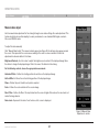
Log in to the web interface, as explained on page 16. The web interface
opens at the Targets page (see Figure 14 on page 16). To connect
to a target or serial device, click the desired target/device in the
Server Name column. (A server being used by another user cannot be
accessed.) The screen of the target/device appears inside a remote
console window.
Toolbar icon – This is the minimized toolbar from which you switch and
configure the system.
Remote Session icon – Hold the mouse over the icon to view
information about current server, connection time, and video mode.
Note! For a user, only permitted targets appear on the Targets page.
Figure 27 illustrates the remote console window.
NOTE: If a user connects to a target device with a higher screen
resolution than the local computer, the remote viewer window will
display a portion of the target device screen, with scroll bars for viewing
the remainder of the screen. The user may view the entire screen by
adjusting the resolution on the target device, the local computer,
or both.
Figure 27 Remote Console window
OmniViewIP 5216K/5232K
4
28
REmote AcCESS
Table of Contents
sections
1
2
3
4
5
The Toolbar
Changing the performance settings
To maximize the toolbar:
You can alter the bandwidth settings from the toolbar.
Click the arrow
To alter the settings:
. Click again to minimize the toolbar.
When maximized, the toolbar can be dragged and dropped to anywhere
on the screen, by dragging the icon
. When minimized, the icon
glides to a side of the screen.
From the toolbar, click . The “Settings...” dialog box appears (see
Figure 28).
To hide the toolbar, either:
Double-click the Switch system tray icon
.
or
Press “F9”.
To display the toolbar, repeat the action above. Also see page XX.
Switching to a different server
To connect to a different server:
1.
From the toolbar, click
or right-click
. A list of available
servers appears. The currently connected server is highlighted
in bold.
2.
Click the desired server name. The screen of the selected
server appears.
OmniViewIP 5216K/5232K
6
Figure 28 Settings.. Dialog box
29
REmote AcCESS
Table of Contents
sections
1
2
3
4
5
Bandwidth
Adjusting the video settings
Choose from the following options:
To change the video settings:
Adaptive – Automatically adapts to the best compression and colors
according to the network conditions. (Not recommended because
network parameters may change frequently, impacting on user
experience.)
From the toolbar, click
Low – Select “Low” for high compression and 16 colors.
Medium – Select “Medium” for medium compression and 256 colors.
Medium is recommended when using a standard Internet connection.
Refresh
•
Manual Video Adjust
•
Auto Video Adjust
. You have the following options:
Each option is explained below.
High – For optimal performance when working on a LAN, select “High”.
This gives a low compression and high colors (16-bit).
Refresh
Custom – You can choose your own compression and color levels.
Click “OK”. The screen of the last accessed target server appears.
OmniViewIP 5216K/5232K
•
6
Select “Refresh” to refresh the video image. Refresh may be needed
when changing the display attributes of a target server.
30
REmote AcCESS
Table of Contents
sections
1
2
3
4
5
6
Manual video adjust
Use the manual video adjustment for fine-tuning the target server video settings after auto adjustment. This
feature should also be used for adapting to a noisy environment, a non-standard VGA signal, or when in
full-screen DOS/CLI mode.
To adjust the video manually:
Click “Manual Video Adjust”. The manual controls appear (see Figure 29). A red frame also appears around
the screen. This represents the screen area according to the server’s screen resolution. Perform the
adjustments inside and relative to this frame.
Brightness/Contrast – Use the scales to adjust the brightness and contrast of the displayed image. Move
the sliders to change the displayed image. Click in the area of the sliders for fine-tuning.
For the following controls, choose the appropriate measurement.
Horizontal Offset – Defines the starting position of each line on the displayed image.
Vertical Offset – Defines the vertical starting position of the displayed image.
Phase – Defines the point at which each pixel is sampled.
Scale – Defines the scale resolution of the session image.
Select Filter – Defines the filter of the input video from the server. A higher filter reduces the noise level, but
makes the image heavier.
Noise Level – Represents the video “noise” when a static screen is displayed.
Figure 29 Manual Video
Adjustments controls
OmniViewIP 5216K/5232K
31
REmote AcCESS
Table of Contents
sections
1
2
3
4
5
Auto video adjust
To adjust the video automatically:
Click “Auto Video Adjust”. The process takes a few seconds. If the
process runs for more than three times, there is an abnormal noise level.
Check the video cable and verify that no dynamic video application is
running on the target server’s desktop.
Perform the procedure where necessary for each target server or new
screen resolution.
Keyboard key sequences
Click
. A list of defined keyboard sequences appears. When
clicked, these transmit directly to the target server, and will not affect
the client computer.
Figure 30 Special Key Manager box
For example, select “Ctrl-Alt-Del” to send this 3-key sequence to the
target server to initiate its shutdown/login process.
To add a predefined sequence:
1.
Click “Add Predefined”. A list of sequences appears.
To add a keyboard sequence:
2.
Select the desired sequence and click “OK”. The sequence
appears in the Special Key Manager box.
3.
Click “OK”. The sequence appears in the Keyboard Key
sequence list.
Click “Add/Remove”. The Special Key Manager box appears (see
Figure 30).
OmniViewIP 5216K/5232K
32
6
REmote AcCESS
Table of Contents
sections
1
2
3
4
5
6
To record a key sequence:
To edit a key sequence:
1.
1.
From the Special Key Manager Dialog box, select the desired key.
2.
Click “Edit”.
3.
Click “Start Recording”.
4.
Press the desired keys. The keys appear in the area provided.
5.
Click “Stop Recording”.
6.
Click “OK”.
From the Special Key Manager box, press “Record New”. The Add
Special Key dialog box appears (see Figure 31).
Figure 31 Add Special Key Dialog box
2.
Give the key sequence a name in the Label field.
3.
Click “Start Recording” and click inside the main window.
4.
Press the desired keys. The key sequence appears in the area
provided.
5.
Click “Stop Recording”.
6.
Click “OK”.
OmniViewIP 5216K/5232K
33
REmote AcCESS
Table of Contents
sections
1
2
3
4
5
Synchronizing mouse pointers
Server-mouse settings for common operating systems:
When working at the client computer, two mouse pointers appear: the
client computer’s is on top of the target server’s. The mouse pointers
should be synchronized. The following explains what to do if they are
not synchronized.
Windows 2000, XP, 2003 Server, Vista
Warning
Before synchronizing mouse pointers, make sure that mouse
acceleration is disabled on all attached target servers (explained
below); otherwise, mouse synchronization may not work.
6
1.
Go to the Windows “Control Panel”.
2.
Select “Mouse” and then navigate to the “Pointer Options” tab.
3.
Make sure the pointer speed slider is in the exact center between
“Slow” and “Fast”.
4.
Uncheck “Enhance Pointer Precision”. In Windows 2000, set the
mouse acceleration to “None”.
Aligning the mice pointers
Before attempting to synchronize the mouse pointer, make sure that
mouse-acceleration settings for the server are properly configured in all
attached servers. Below is a list of common operating system mouseacceleration settings.
Note for Windows Servers
1. W
indows enables mouse acceleration at the login screen by
default. Make sure you are logged in to windows to check
mouse synchronization.
2. M
ouse acceleration can only be disabled on a per Windows
user basis. If you log in to Windows with a different user name,
then you will have to disable mouse acceleration separately for
that user as well.
OmniViewIP 5216K/5232K
34
REmote AcCESS
Table of Contents
sections
1
2
3
4
5
6
Red Hat®, Fedora, and other Linux distributions
When accessing the target server, the mice may appear at a distance to
each other.
1.
Go to “Mouse Preferences”.
To align the mouse pointers:
2.
Then navigate to the “Motion” tab.
3.
Set the “Acceleration” to five clicks from left.
4.
Set the “Sensitivity” to three clicks from left.
5.
Set the “Threshold” to two clicks from left.
OmniViewIP 5216K/5232K
From the toolbar, click “ / Align” or press (left) “Ctrl+M”
simultaneously. The mice will align.
35
REmote AcCESS
Table of Contents
sections
1
2
3
4
5
6
Manual settings
2.
If the mouse settings on the target server were ever changed, or when
the operating system on the target server is Windows XP, 2003 Server,
Vista, or 2008 Server, or Linux, Novell, SCO UNIX®, or Sun Solaris, you
must configure the mouse manually.
Select the target server’s operating system and click “OK”.
Instructions and sliders appear. Note: You must do this
configuration on every port.
3.
Follow the instructions and set any relevant sliders to the same
values as set in the target server’s “Mouse Properties” window.
To manually configure the mouse:
4.
Check USB if the SIM you are using is USB type.
1.
Click “OK”. The mouse pointers should be synchronized. There will be
no need to perform this setup unless you change the server attached to
the particular port.
From the toolbar, click “
/ Manual Settings”. The “Mouse
Settings” dialog box appears (see Figure 32).
Figure 32 Mouse Settings Dialog box
OmniViewIP 5216K/5232K
36
REmote AcCESS
Table of Contents
sections
1
2
3
4
5
6
Advanced – Mouse emulation
Click
Figure 33).
and the “Mouse Emulation” dialog box appears (see
Figure 34 Mouse Emulation dialog box for use with touch pads
Press “OK” to save settings.
Note:
This “Mouse Emulation” setting is used to determine the correct reset
sequence for a local mouse. Setting it incorrectly may lead to a jumpy or
non-operational local console mouse after a remote user disconnects it
from the Switch.
Figure 33 Mouse Emulation dialog box
Max Rate - This defines the maximum mouse report rate. For Sun
Solaris, the default value is 20 in order to support older Sun versions.
If a 2-button mouse (older mice without wheel capability, most of the
touch pads, trackballs, or integrated keyboards with mice used in most
of the rack drawers) is connected to the local KVM port of the Switch,
set the “Mouse Emulation” to “Standard Mouse” (see Figure 34).
OmniViewIP 5216K/5232K
37
REmote AcCESS
Table of Contents
sections
1
2
3
4
Calibrating mice pointers
Adjustments in general
A target server may have a different mouse pointer speed to the client
computer. Calibrating automatically discovers the mouse speed of the
target server and aligns the two pointers.
The above adjustments, namely:
•
Performance settings
To perform the calibration when the target server’s operating system is
Windows NT® 4, 2000, or 98:
•
Video settings
•
Keyboard key sequences
•
Synchronizing mouse pointers
From the toolbar, click “
/ Calibrate”. The Switch saves this
alignment so calibration is only needed once per target server.
If the video noise level is above zero, calibration may not work. Go to
“Video Adjustment” and try to eliminate the noise by pressing “Auto
video adjust” and/or adjusting the bars in manual video adjust. Then
perform the mouse calibration.
may have to be performed twice for each target.
Note! If the mouse settings on the target server were ever changed, you
must synchronize mouse pointers manually, as explained below.
OmniViewIP 5216K/5232K
5
38
6
REmote AcCESS
Table of Contents
sections
1
2
3
Globe icon menu features
5
6
Hide Toolbar – Check this option to hide the toolbar from the next
reconnection onward. To toggle the toolbar on and off, press “F9” or
double-click the system tray icon
.
Right-click the globe icon
and a menu appears. From this menu you
can access the connected devices. You also have the following features:
Full-Screen Mode – Check this option to make the remote session
screen appear in full-screen mode from the next reconnection onward.
To toggle the full-screen mode on and off, press “F11” (also see the
next section).
Disconnect – You can disconnect the session by clicking “Disconnect”.
About – Click “About to verify the Client, Firmware and Switch” file
versions installed on your Switch.
Virtual Media – Click this option to mount virtually any removable mass
storage devices connected to the client computer onto the target server.
Local Settings – Click “Local settings” and the “Client Configuration”
dialog box appears (see Figure 35).
Figure 35 Client Configuration dialog box
Pointer Type – From the drop-down menu, you can change the client
computer mouse pointer to appear as a dot or to not appear at all.
OmniViewIP 5216K/5232K
4
39
REmote AcCESS
Table of Contents
sections
1
2
3
Virtual media
4
5
6
Mounting a Drive
1.
With virtual media, you can virtually mount removable mass storage
devices connected to the client computer onto the target server.
Click “Virtual Media” and the “Virtual Media” dialog box appears
(see Figure 36). All connected mass storage devices appear in the
“Local Drives” section.
This includes:
•
Floppy drives
•
CD-ROMs
•
DVD-ROMs
•
ISO images of CD\DVD
•
USB flash drives (disk on key tokens)
•
Miscellaneous USB memory sticks/cards identified by the operating
system as removable mass storage devices
Setup
Virtual media is only supported by server ports 1 and 2. You must
connect a separate USB cable to VM ports 1 and 2 located on the back
of the Switch and match to the corresponding servers connected to
server ports 1 and 2.
OmniViewIP 5216K/5232K
Figure 36 Virtual Media
40
2.
Select the device to be mounted and click “Mount”. A remote
device warning should appear.
3.
Click “OK”. The device mounts onto the target server and
appears as a removable or CD/DVD drive of the target server. It
also appears in the “Mounted Drives” section in Figure 36. Once
mounted, you can use the device during the remote session as if it
is connected to the target server.
REmote AcCESS
Table of Contents
sections
1
2
3
Mounting an ISO file
An ISO image (.iso) is a disk image of an ISO 9660 file system, and
refers to any optical disc image, even a UDF image. In addition to the
data files in the ISO image, it also contains all the file system metadata,
including boot code, structures, and attributes. All of this information
is contained in a single file. These properties make it an attractive
alternative to physical media for the distribution of software that requires
this additional information as it is simple to retrieve over the Internet.
Because virtual media emulates USB 1.1 over a TCP connection, it has a
number of limitations that govern the virtual-media compatibility
and operation.
•
Virtual media emulates USB 1.1. It doesn’t emulate USB 2.0.
•
Virtual media redirects the client’s local DVD/CD or removable
mass storage devices to a target server during the open client
session only. This means if the remote client session disconnects,
the mounted drives will be automatically dismounted from the
target server.
•
Maximum data transfer speed of the virtual media doesn’t
exceed 5.0Mbps.
OmniViewIP 5216K/5232K
41
5
6
•
Only drives identified by the client’s operating system as drives
with removable storage can be mounted as virtual media. Many
USB-attached hard disks identify themselves to the operating
system as hard-disk drives and can’t be used for virtual-media
mounting.
•
Booting from a mounted virtual-media drive is possible only if the
target server supports booting from USB-attached storage.
•
Currently, it is not possible to boot a target server from Linux
distribution mounted as virtual media.
•
Windows CD/DVD, or its modifications such as Winternals ERD
Commander, WinPE, BartPE, or similar, can be used for booting
the target server when mounted as virtual media.
•
Mounting removable mass storage devices such as USB flash
drives (disk on key tokens) or miscellaneous USB memory sticks/
cards will remove them from the client’s operating system and
redirect them with read/write access permissions to the target
server to ensure the integrity of write operation.
•
Connection timeout will not occur at the time the virtual media
remains mounted.
To mount an ISO file, click “Mount ISO File”, locate the file, and mount it.
Things to know about operation of the virtual media
4
REmote AcCESS
Table of Contents
sections
1
2
3
4
5
6
Full-screen mode
Disconnecting the remote session
Work on the target server as if you are working on a local computer with
full-screen mode.
To disconnect the session, click
on the toolbar. The Login page
appears. You can re-log in, or close the browser window to disconnect
the session.
To work in full-screen mode:
1.
Ensure that the client’s computer has the same screen resolution
as the target server.
The Targets Page Menu
2.
Press “F11”. The Internet Explorer window disappears, leaving the
Internet Explorer menu bar at the top.
When logging in to the system as an administrator or a user, you reach
the Targets page (see Figure 14 on page 16). From the menu, you can:
3.
Right-click the Internet Explorer menu bar and check “Auto-Hide”.
The Internet Explorer menu bar disappears. You are in
full-screen mode.
To exit full-screen mode:
Change the password
•
See an event log
Note! Only an administrator has the configuration option in the menu.
Press “F11”, or place the mouse at the top of the window to display the
Internet Explorer toolbar and click the “Restore” button.
Note! Full-screen mode can also be activated from the toolbar menu
(see page 29).
OmniViewIP 5216K/5232K
•
42
REmote AcCESS
Table of Contents
sections
1
2
3
4
5
6
Changing the password
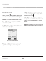
To change the password, click “Password” from the menu and the
following appears.
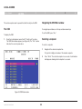
Figure 37 Events log
Navigate through the event pages using the forward or backward
arrows, marked as (A) in Figure 37.
Figure 36 Password
From the drop-down menu, marked as (B) in Figure 37, choose the
number of events that will appear on each page (10–40).
Type a new password according to the password policy set (see
page 19).
Downloading the log
Event log
You can download and save the log.
To do so, click
and save as a “.csv” file. The file can be
viewed using Microsoft Excel® or compatible software.
To see a log of all system events:
From the menu, select “Event Log” and the following screen appears.
Clearing the log
To clear the log, click
to save the log.
OmniViewIP 5216K/5232K
43
. A prompt appears asking if you first want
LOCAL ACCESS
Table of Contents
sections
1
2
3
4
5
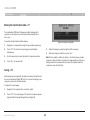
This section explains how to operate the Switch locally via the OSD.
Navigating the OSD Main window
The OSD
To navigate up and down, use the up and down arrow keys.
6
To exit the OSD, press “Esc”.
To display the OSD:
1.
Selecting a computer
From the local keyboard, press the left “Scroll Lock” key twice.
The OSD Main window appears (see Figure 38). The “Pwr” column
indicates the server is powered on.
To select a computer:.
Figure 38 OSD Main window
OmniViewIP 5216K/5232K
44
1.
Navigate to the desired computer line.
Or, type the 2-digit port number of the desired computer.
2.
Press “Enter”. The selected computer is accessed. A confirmation
label appears showing which computer is accessed.
LOCAL ACCESS
Table of Contents
sections
1
2
3
4
5
6
Moving the Confirmation label – F1
The confirmation OSD label that appears briefly showing which
computer is currently accessed can be positioned anywhere on
the screen.
To position the label from the Main window:
Figure 39 Image Tuning label
1.
Navigate to a computer line using the up and down arrow keys.
2.
Press “F1”. The selected screen image and confirmation
label appear.
3.
Adjust the image by using the right and left arrow keys.
4.
When the image is satisfactory, press “Esc”.
3.
Use the arrow keys to move the label to the desired position.
4.
Press “Esc” to save and exit.
Note! Picture quality is relative to distance. The farther away a remote
computer is from the Switch, the lower the image quality, and the more
tuning needed. We recommend that you place the higher-resolution
computers closer to the Switch.
Tuning – F5
Video tuning may be required if the distance between the Switch and
the server is between 50 and 100 feet. You can tune the image of any
computer screen from the Main window.
To adjust the screen image:
1.
Navigate to the computer line you wish to adjust.
2.
Press “F5”. The screen image of the selected computer appears
together with the Image Tuning label (see Figure 39).
OmniViewIP 5216K/5232K
45
LOCAL ACCESS
Table of Contents
sections
1
2
3
The Settings window – F2
4
5
6
5000HQ MNG – Press the space bar to toggle between enabling and
disabling management by the 5000HQ. When enabled, the Switch is
remotely managed by OmniView IP Central Management
Appliance 5000HQ.
Press “F2”. The Settings window appears (see Figure 40).
5000HQ ADD – Here you can change the static IP address of
the 5000HQ.
HOT KEY – Pressing “Scroll Lock” twice in quick succession will make
the OSD appear. You can replace “Scroll Lock” with any of the other
hot-key options following:
Figure 40 Settings window
Ctrl, Ctrl (left Ctrl key only)
•
Ctrl, F11 (left Ctrl key only)
•
Print Screen
Press the space bar to toggle between options. To display the OSD in
the future, press the new hot key.
In the Settings window, navigate downward using the “Tab” key. At
the bottom of the window, press “Tab” to go to the top of the window.
Change settings by typing in the selected area or by pressing the space
bar, whichever is relevant.
KEYBOARD LANGUAGE – Press the space bar to toggle between the
language options. It can be changed to French or German.
From this window, you can do the following:
Changing the network parameters from the OSD is explained with the
initial configuration in the “Setting the IP Address” section on page 13.
OmniViewIP 5216K/5232K
•
46
LOCAL ACCESS
Table of Contents
sections
1
2
3
4
5
DDC – F10
Saving changes to the settings
Display Data Channel (DDC) is a VESA standard for communication
between a monitor and a video adapter.
To save changes to the settings and return to the Main window,
press “Esc”.
From the Settings window, input the DDC information of the monitor
connected to the Switch into the memories of all connected SIMs when
first installing the system.
To input the DDC information:
Press “F10”. “Please wait” flashes a few times and disappears. The
monitor’s DDC information is sent to all SIMs.
Updating the DDC information
Update the DDC information in any of the following circumstances:
•
When replacing the monitor connected to the Switch
•
When adding a new SIM to the system
•
When reconnecting an existing SIM that was temporarily used in a
different system
To update the DDC information, repeat the steps as set out above.
OmniViewIP 5216K/5232K
47
6
Additional information
Table of Contents
sections
1
2
3
4
5
Technical Specifications
Target Server
Operating Systems
Dimensions (H x D x W)
44 x 270 x 431mm/1.7 x 10.6 x 17 in.
Power Input
100–240VAC, 0.8A, 50/60Hz
Operating Temperature
0° C to 40° C/32° F to 104° F
Storage Temperature
-40° C to 70° C/-40° F to 158° F
Humidity
80% non-condensing relative humidity
Windows, Novell, Linux, Sun Solaris
Client Computer
Windows 2000 or higher with IE 6.0 or higher and ActiveX
Target Server
Up to 1600x1200@85Hz
Resolution
Client Computer
Recommended - resolution should be higher than on the
target server
Distance from Switch to SIMs
Up to 30m/99 ft.
Video and Mouse Synchronization
Both auto and manual modes
Security
PS/2 SIM
USB SIM
VGA - HDD15
VGA - HDD15
KM - MiniDIN6
KM - USB
System - RJ45
System - RJ45
Power
From keyboard port
From USB port
Local KVM Connection – Screen HDD15, Keyboard/
Mouse – 2 USB
Product Weight
100g/0.20 lbs.
Servers – RJ45
Shipping Weight
172g/0.38 lbs.
2.343kg./5.165 lbs.
Dimensions
65 x 25 x 25mm/0.21 x 0.08 x 0.08 in.
Connections
128-bit SSL encryption, 256-bit AES encryption
Ethernet – RJ45 – 10/100bps auto-sensing
Serial – RJ45 x 2
Connections
Weight
OmniViewIP 5216K/5232K
48
6
Additional information
Table of Contents
sections
1
2
3
4
6
5
Video Resolution and Refresh Rates
Hz
56
640x480
60
65
x
66
70
72
x
x
x
720x400
800x600
1024x768
75
76
x
x
x
x
x
x
x
x
x
x
x
x
1152x900
x
1280x720
x
1280x768
x
1280x960
x
1280x1024
x
1600x1200
x
x
x
x
x
x
86
x
x
x
85
x
x
1152x864
OmniViewIP 5216K/5232K
73
x
x
x
49
x
x
x
x
Additional information
Table of Contents
sections
1
2
3
Safety
This device contains no serviceable parts. Any servicing of the device
must be performed by Belkin International, Inc.
User Manual Feedback
Your feedback is very important to help us improve our documentation.
Please email any comments to: [email protected].
Please include the following information: Manual name, part number,
and P number.
Product Registration
You may register your product online by going to
https://www.belkin.com/registration/.
This will assist Belkin in contacting you regarding important information
regarding the use of your product.
OmniViewIP 5216K/5232K
50
4
5
6
Additional information
Table of Contents
sections
1
2
3
4
5
6
Information
FCC Statement
DECLARATION OF CONFORMITY WITH FCC RULES FOR ELECTROMAGNETIC COMPATIBILITY
CE Declaration of Conformity
We, Belkin International, Inc., of 501 West Walnut Street, Compton, CA
90220, declare under our sole responsibility that the products:
We, Belkin International, Inc., declare under our sole responsibility that
the products F1DP216G, F1DP232G, to which this declaration relates,
are in conformity with Emissions Standard EN55022 and with Immunity
Standard EN55024, LVP EN61000-3-2, and EN61000-3-3.
F1DP216G, F1DP232G
to which this declaration relates:
This equipment has been tested and found to comply with the limits
for a Class A digital device, pursuant to Part 15 of the FCC Rules.
These limits are designed to provide reasonable protection against
harmful interference when the equipment is operated in a commercial
environment. This equipment generates, uses, and can radiate radio
frequency energy and, if not installed and used in accordance with
the instruction manual, may cause harmful interference to radio
communications. Operation of this equipment in a residential area
is likely to cause harmful interference in which case the user will be
required to correct the interference at his or her own expense.
OmniViewIP 5216K/5232K
ICES
This Class A digital apparatus complies with Canadian ICES-003. Cet
appareil numérique de la classe A est conforme á la norme NMB-003 du
Canada.
51
Additional information
Table of Contents
sections
1
2
3
4
5
6
Belkin International, Inc., Limited 2-Year Product Warranty
What this warranty covers.
and tear, erosion, depletion, obsolescence, abuse, damage due to low
voltage disturbances (i.e., brownouts or sags), non-authorized program,
or system-equipment modification or alteration.
Belkin International, Inc. (“Belkin”) warrants to the original purchaser of
this Belkin product that the product shall be free of defects in design,
assembly, material, or workmanship.
How to get service.
What the period of coverage is.
To get service for your Belkin product you must take the following steps:
Belkin warrants the Belkin product for two years.
1.
Contact Belkin Ltd., Express Business Park, Shipton Way, Rushden
NN10 6GL, United Kingdom, Attn: Customer Service, or call
(800)-223-5546, within 15 days of the Occurrence. Be prepared to
provide the following information:
a. The part number of the Belkin product.
b. Where you purchased the product.
c. When you purchased the product.
d. Copy of original receipt.
2.
Your Belkin Customer Service Representative will then instruct
you on how to forward your receipt and Belkin product and how to
proceed with your claim.
What will we do to correct problems?
Product Warranty.
Belkin will repair or replace, at its option, any defective product free of
charge (except for shipping charges for the product). Belkin reserves the
right to discontinue any of its products without notice, and disclaims any
limited warranty to repair or replace any such discontinued products.
In the event that Belkin is unable to repair or replace the product (for
example, because it has been discontinued), Belkin will offer either a
refund or a credit toward the purchase of another product from Belkin.
com in an amount equal to the purchase price of the product as
evidenced on the original purchase receipt as discounted by its natural
use.
What is not covered by this warranty?
All above warranties are null and void if the Belkin product is not
provided to Belkin for inspection upon Belkin’s request at the sole
expense of the purchaser, or if Belkin determines that the Belkin product
has been improperly installed, altered in any way, or tampered with.
The Belkin Product Warranty does not protect against acts of God such
as flood, lightning, earthquake, war, vandalism, theft, normal-use wear
OmniViewIP 5216K/5232K
52
Additional information
Table of Contents
sections
1
2
3
Belkin reserves the right to review the damaged Belkin product. All
costs of shipping the Belkin product to Belkin for inspection shall be
borne solely by the purchaser. If Belkin determines, in its sole discretion,
that it is impractical to ship the damaged equipment to Belkin, Belkin
may designate, in its sole discretion, an equipment repair facility to
inspect and estimate the cost to repair such equipment. The cost, if any,
of shipping the equipment to and from such repair facility and of such
estimate shall be borne solely by the purchaser. Damaged equipment
must remain available for inspection until the claim is finalized.
Whenever claims are settled, Belkin reserves the right to be subrogated
under any existing insurance policies the purchaser may have.
5
6
Some states do not allow limitations on how long an implied warranty
lasts, so the above limitations may not apply to you.
IN NO EVENT SHALL BELKIN BE LIABLE FOR INCIDENTAL, SPECIAL,
DIRECT, INDIRECT, CONSEQUENTIAL OR MULTIPLE DAMAGES SUCH
AS, BUT NOT LIMITED TO, LOST BUSINESS OR PROFITS ARISING
OUT OF THE SALE OR USE OF ANY BELKIN PRODUCT, EVEN IF
ADVISED OF THE POSSIBILITY OF SUCH DAMAGES.
This warranty gives you specific legal rights, and you may also have
other rights, which may vary from state to state. Some states do not
allow the exclusion or limitation of incidental, consequential, or other
damages, so the above limitations may not apply to you.
How state law relates to the warranty.
THIS WARRANTY CONTAINS THE SOLE WARRANTY OF BELKIN.
THERE ARE NO OTHER WARRANTIES, EXPRESSED OR, EXCEPT AS
REQUIRED BY LAW, IMPLIED, INCLUDING THE IMPLIED WARRANTY
OR CONDITION OF QUALITY, MERCHANTABILITY OR FITNESS FOR A
PARTICULAR PURPOSE, AND SUCH IMPLIED WARRANTIES, IF ANY,
ARE LIMITED IN DURATION TO THE TERM OF THIS WARRANTY.
OmniViewIP 5216K/5232K
4
53
Additional information
Table of Contents
sections
1
2
3
Technical Support
You can find technical-support information on our website,
www.belkin.com, by navigating to the tech-support section.
If you want to contact technical support by phone, please call the number
you need from this list*:
*Local rates apply.
OmniViewIP 5216K/5232K
54
4
5
Country
Number
Internet adress
AUSTRIA
0820 200766
www.belkin.com/de/
BELGIUM
07 07 00 073
www.belkin.com/nl/
www.belkin.com/fr/
CZECH REPUBLIC
239 000 406
www.belkin.com/uk/
DENMARK
701 22 403
www.belkin.com/uk/
FINLAND
0972519123
www.belkin.com/uk/
FRANCE
08 - 25 54 00 26
www.belkin.com/fr/
GERMANY
0180 - 500 57 09
www.belkin.com/de/
GREECE
00800 - 44 14 23 90
www.belkin.com/uk/
HUNGARY
06 - 17 77 49 06
www.belkin.com/uk/
ICELAND
800 8534
www.belkin.com/uk/
IRELAND
0818 55 50 06
www.belkin.com/uk/
ITALY
02 - 69 43 02 51
www.belkin.com/it/
LUXEMBOURG
34 20 80 85 60
NETHERLANDS
0900 - 040 07 90
NORWAY
81 50 0287
www.belkin.com/uk/
POLAND
00800 - 441 17 37
www.belkin.com/uk/
PORTUGAL
707 200 676
www.belkin.com/uk/
RUSSIA
495 580 9541
www.belkin.com/networking/
SOUTH AFRICA
0800 - 99 15 21
www.belkin.com/uk/
SPAIN
902 - 02 43 66
www.belkin.com/es/
SWEDEN
07 - 71 40 04 53
www.belkin.com/uk/
SWITZERLAND
08 - 48 00 02 19
www.belkin.com/de/
www.belkin.com/fr/
UNITED KINGDOM
0845 - 607 77 87
www.belkin.com/uk/
OTHER COUNTRIES
+44 - 1933 35 20 00
www.belkin.com/uk/
€0.10 per minute
www.belkin.com/nl/
6
Belkin Ltd.
Express Business Park
Shipton Way, Rushden
NN10 6GL, United Kingdom
Belkin SAS
130 rue de Silly
92100 Boulogne-Billancourt,
France
Belkin GmbH
Hanebergstrasse 2
80637 Munich
Germany
Belkin Iberia
C/ Anabel Segura, 10 planta baja, Of. 2
28108, Alcobendas, Madrid
Spain
Belkin Italy & Greece
Via Carducci, 7
Milano 20123
Italy
Belkin B.V.
Boeing Avenue 333
1119 PH Schiphol-Rijk,
Netherlands
© 2009 Belkin International, Inc. All rights reserved. All trade names are registered trademarks of respective
manufacturers listed. Windows, Windows Vista, Microsoft, NT, Internet Explorer, and ActiveX are either
registered trademarks or trademarks of Microsoft Corporation in the United States and/or other countries.
PM00020ea - F1DP2XXGea