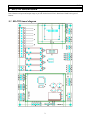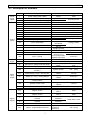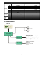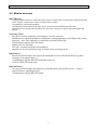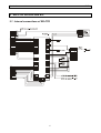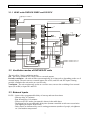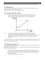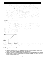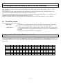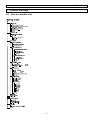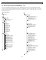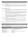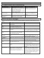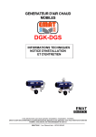
1
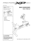
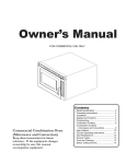
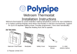
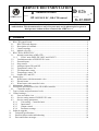
SERVICE DOCUMENTATION
Chapter:
D
Ventilation of houses
02
DUPLEX EC , RD-CTR control
D 02b
_
02
Section:
ATREA s.r.o.
Valid from
16.12.2009
This documentation is intended solely for service technicians with a valid service
authorization. This documentation or any of its parts may not be photocopied or given to
third persons without written consent from ATREA s.r.o.
1 Contents
1
2
Contents .......................................................................................................................................1
RD-CTR control board.................................................................................................................2
2.1
RD-CTR board diagram.......................................................................................................2
2.2
Description of terminals.......................................................................................................3
2.3
Control topology ..................................................................................................................4
2.4
Module overview .................................................................................................................5
3
RD-CTR for DUPLEX EC ..........................................................................................................6
3.1
Internal connections of RD-CTR .........................................................................................6
3.1.1
HVAC units DUPLEX 230EC and 250 ECV..............................................................7
3.2
Ventilation modes of DUPLEX EC units ............................................................................7
3.3
External inputs .....................................................................................................................7
3.4
Stop contact..........................................................................................................................8
3.5
Analogue inputs IN1 and IN2 ..............................................................................................8
3.6
Temperature sensor TA........................................................................................................8
3.7
TE temperature sensor .........................................................................................................9
3.8
Temperature sensor TI2 .......................................................................................................9
3.9
Outputs SZ1 and SZ2.........................................................................................................10
4
Heater types................................................................................................................................10
4.1
Water heater with thermostatic valve.................................................................................10
4.2
Electric heater ....................................................................................................................11
4.3
Water heater with controlled valve ....................................................................................11
5
Maintenance functions ...............................................................................................................11
6
Description and functions of the CP 08 RD controller ..............................................................12
6.1
Controller modes................................................................................................................12
7
Types of units and performance levels.......................................................................................12
8
Control settings ..........................................................................................................................13
8.1
User-accessible view..........................................................................................................13
8.2
Service setting menu of DUPLEX EC units ......................................................................14
8.3
Service setting parameters .................................................................................................15
8.3.1
Unit setting – Controlled unit.....................................................................................15
8.3.2
Input status .................................................................................................................15
8.3.3
Output control ............................................................................................................15
8.3.4
Parameter settings ......................................................................................................15
9
Software upgrade .......................................................................................................................17
10
Technical specifications.........................................................................................................17
11
Possible failures and troubleshooting ....................................................................................18
12
Error and failure messages.....................................................................................................18
Service documentation
Atrea s.r.o.
D02b
2 RD-CTR control board
The RD-CTR control board is used for controlling DUPLEX RD and EC series HVAC units. The RD-CTR
board features an input and output range to provide for the basic HVAC functions of both basic types of
heaters.
2.1 RD-CTR board diagram
2
Service documentation
Atrea s.r.o.
D02b
2.2 Description of terminals
Power
supply
inputs
Control
inputs
Motor
output
Terminal
Description
L
Power supply (230V, 50Hz)
24V
24V
D1
N1
D2
N2
D3
N3
D4
N4
STP
GN
Control module board power supply
Control module board power supply
Input No.1
Neutral No.1
Input No.2
Neutral No.2
Input No.3
Neutral No.3
Input No.4
Neutral No.4
Input – STOP contact
Input - ground
TR
Input - thermostat
GN
Input – ground
IN1
Input – analogue control (0 – 10V)
GN
IN2
Input – ground
Input – analogue control (0 – 10V)
GN
Input – ground
Mc
Mv
Circulation fan
Ventilation fan
SV
Servo drive- underground exchanger
SB
Servo drive –bypass
Servo drive –bypass (inversion
function)
SBI
Servo
drive
output
Signal
outputs
24V
Power supply (+24V) – servo 0-10V
SC
Control (0 – 10V) – mixing damper
LS
Control (0 – 10V) – TPO junction,
electric heater
GN
Ground - servo 0-10V
SZ1
SZ2
Zone ventilation servo drive 1
Zone ventilation servo drive 2
YV1
Output – EUV1
YV2
Output – EUV2
K
K
GN
EXT
Output – boiler (voltage-free switch
contact)
Output – boiler (voltage-free switch
contact)
Output - ground
Output - programmable (reserve)
3
Purpose
Servo drive power
supply
Type
230V
24V DC/18V AC
Toilet, bathroom
230V [2mA]
Toilet, bathroom
230V [2mA]
Toilet, bathroom
230V [2mA]
Kitchen
230V [2mA]
E.g. fire alarm
Voltage contact
Bathroom
thermostat
Voltage contact
Sensor
C02,φ,hygrostat
0-10V SS *
As IN1, or
replacement of
D11, input for CRK,
capilary thermostat
Mc control
Mv control
Damper ZVT/pump
ZVTs
Bypass damper
Bypass damper
Mixing damper
control
Mixing damper
control
0-10V SS *
0-10V SS *
0-10V SS *
0-10V SS *
0-10V SS *
230V/50Hz Relay
0.5A
24V [2VA]
24V
[2VA]
24V SS
0-10V SS *
0-10V SS *
Mixing damper
control
Zone 1 damper
Zone 2 damper
Heating branch
valve 1
Heating branch
valve 2
Heat source
activation
Heat source
activation
Ground
24V [2VA]
24V [2VA]
230V
230V
Relay 230V / 0,5A
Ground
E.g. closed with D4
on (kitchen
extraction)
24V [2VA]
Service documentation
Sensors
VC
TA sensor power supply
TA
TA sensor
GN
VC
TA sensor ground
Ti2 power supply
TI2
TI2 sensor, manostat PFR
GN
TE
Ground, manostat
TE sensor (+24V)
TE sensor (measurement resistor to
ground)
Controller power supply
Controller communication
Ground (controller)
External board EXP power supply
Communication with EXP
Ground
TE
Controller
External
board
EXP
Atrea s.r.o.
PW
COM1
GN
PW
COM2
GN
D02b
+5 V
Communication with
sensor
Ground
+5 V
Communication with
sensor
Ground
24 V SS
Resistor to ground
12V/SS
Specification HW LIN
Ground
12V/SS
Specification HW LIN
Ground
2.3 Control topology
CP-08
Mc
EC fans
Mv
RD-CTR
RD-IO
Heat pump control
Fan speed control according to the
pressure relations
Circulation ground heat exchanger
Condensing boiler control
RD-COM
Superior contrl system
(ModBUS)
Backup of settings
Internet
4
Service documentation
Atrea s.r.o.
D02b
2.4 Module overview
RD-CTR board
-
Contains program features to control the entire system, evaluates data on temperatures measured and the
status of inputs, on the basis of which it switches HVAC modes,
Communicates with all other modules,
Contains inputs and outputs for the basic HVAC accessories of DUPELX R and EC units,
Depending on the setting of the unit (RD or EC) provides a respective range of individual inputs and
outputs.
Controller CP-08
- Sets HVAC modes (manually or according to a weekly program)
- Substitutes for a thermostat function (temperature settings manually or according to the weekly
program) – only if the controller is connected to the unit DUPLEX R_
- Communicates with the RD-CTR board,
- Displays HVAC unit status.
- Sets zone ventilation and other functionalities
- Depending on the unit installed the range of displayed data and setting menus
RD-IO board
- The board contains inputs and outputs for additional devices for DUPLEX R units (ground
exchanger, heat pump control…),
- Communicates with the RD-CTR board that controls it,
- Used for DUPLEX R units only
RD-COM board
- The board contains inputs and outputs for communication with external devices – superior
control, Internet, signalling devices ,
- Communicates with the RD-CTR board.
5
Service documentation
Atrea s.r.o.
3 RD-CTR for DUPLEX EC
3.1 Internal connections of RD-CTR
6
D02b
Service documentation
Atrea s.r.o.
D02b
3.1.1 HVAC units DUPLEX 230EC and 250 ECV
Napájení ventilátorů
L
N
PE
PE
PE
N
N
L
L
D1
N1
D1
N1
D2
N2
D3
N3
D2
N2
D3
N3
D4
N4
YV1
YV2
SV
K
K
D4
N4
YV1
YV2
SV
C
-V
+V
Pojistka 2A - f
GN
TI2
VC
GN
TA
VC
SZ1
SZ2
TE1 (ADS110)
SZ1
SZ2
SB
SBI
3
2
1
SB
TA
SK
GN
GN
24V
24V
GN
Mc
Mv
12V
GN
COM1
PW
GN
SC
SK
24V
I1
I2
GN
S13
GN
IN1
IN2
EXT
EXT
77 °C
GN
TE
VC
GN
COM2
PW
GN
TR
GN
STP
Ti2
GN
TA
VC
K
K
GN
COM
PW
TR
GN
STP
IN1
GN
IN2
Zdroj
24 V DC
24V/DC
18V/AC
O1
O2
GN
Ovládání ventilátoru Me 0-10 V
Ovládání ventilátoru Mi 0-10 V
DEL-A
3.2 Ventilation modes of DUPLEX EC units
The unit offers 3 basic ventilation modes:
Off – the unit is switched off; it only reacts to external outputs,
Periodic ventilation – the unit switches on automatically at set intervals or depending on the use of
external inputs. The unit reacts to external inputs (D1 to D4) and IN1 and IN2 inputs. During
periodic ventilation the unit works at a set flow rate.
Ventilation– The unit continuously works at a set flow rate, reacts to the switching of an external
input (D2 to D4) or input IN1 and IN2.
3.3 External inputs
D1-D3 – inputs with a programmable delay of start-up and run-down times
- Start-up delay 0-5 minutes
- Run-down delay 0-10 minutes
- Effects on HVAC modes just started is shown in the table above
- Each input has its own adjustable delay time (button-controlled switch-on or association
with lighting activation in the room)
- Delay times are influenced by service setting parameters (number of people, air tightness
etc.) and outdoor temperature.
7
Service documentation
Atrea s.r.o.
D02b
D4 – switches a mode on and off according to the table above without delay or run-down times.
3.4 Stop contact
When STP and GN terminals open, the fans of the HVAC unit stop and all dampers are closed
(respective outputs have no voltage or are open).
At that point, the CP-08 RD controller displays “STOP“.
3.5 Analogue inputs IN1 and IN2
IN1
– A universal 0-10V input or a switch contact – distinguishable by a parameter
- Controls ventilation depending on humidity and CO2 concentration sensors
- During control via 0-10V control limits may be set – point A and point B
IN2
– a universal 0-10V input or a switch contact – distinguishable by a parameter
- Controls ventilation depending on humidity and CO2 concentration sensors ,
- During control via 0-10V control limits may be set – point A and point B, same as IN1
- When IN1 and IN2 inputs are combined, ventilation runs according to a higher
requirement
Note: When the input is set as contact (on/off), then only the demanded power performance is set by
parameters in the service menu. The set level of the performace is activated when the inpit (IN1 or
IN2) is connected to the GN terminal.
3.6 Temperature sensor TA
The TA sensor is not mounted on the HVAC unit defaultly – protective thermocontact is conected
between the TA and GN terminals.
When any heater is add to the system, the TA duct temperature sensor must be mounted behind the
heater. Use the ADS120 sensor.
1. The sensor monitors maximum temperature behind the heater, a range between 20 and
50°C can be set by a parameter. When this temperature value is exceeded, the heater (or
the heat source) turns off, and is started again after the temperature has dropped 3 °C
below the selected limit.
2. The sensor monitors the exchanger freezing.
8
Service documentation
Atrea s.r.o.
D02b
When TA drops to ≤ 12 °C ... 1st anti-freeze protection is signalized, return to above
14 °C
- When TA drops to ≤ 7 °C , only when the “water heater” is selected”,
- If the unit’s performance is OFF, KK and YV1 outputs close (to switch
on heating), the SB output opens (to close the bypass), the CP-08 shows
“2nd anti-freeze protection”, does not respond to external signals. The fans
are stopped in this case.
3. Anti-freeze protection: if TA> 77°C, all dampers then close (servo drive terminals without
power supply), fans are off, the CP-08 RD shows “High TA temperature”.
4. If an electric heater is connected to the DUPLEX EC unit, the thermostat function is
blocked depending on the Ti room temperature. The weekly thermostat program applies to
TA temperature control, i.e. temperature behind the heater.
5. If no electric heater is connected to the EC unit (parameter 204 = Tpy), the CP-08 may
substitute for the thermostat function – depending on the relationship between required
and room temperature is closed the K-K contact.
-
3.7 TE temperature sensor
-
Outdoor temperature sensor
- Controls the bypass damper:
- At temperature TE>TEmin the bypass damper is open. TEmin is determined by the
parameter “267 Bypass Dt”.
- At temperature TE>TEmax the bypass damper is closed. TEmin is determined by the
parameter “268 Bypass Ht”.
-.
Reduces the ventilation run-down time when activated by inputs D1 to D3:
Reduction is permitted within 0-100%
Lower temperature interval (-15, 0°C)
Higher temperature Interval (5, 10°C)
The parameters of ventilation time reduction are calculated automatically on the basis of the number of people,
the walled area, the airtightness of the building and the calculation temperature.
3.8 Temperature sensor TI2
1. Anti-freeze protection: if Ti2> 77°C, all dampers then close (servo drive terminals without power
supply), fans are off, the CP-08 RD shows “High TI2 temperature”.
2. Anti-freeze protection of the heat exchanger: if temperature TI2 is lower than the selected minimum,
fans Me and Mi are turned on according to the table below, the CP-08 RD show the text “Recovery
frozen”, the bypass damper closes.
9
Service documentation
Atrea s.r.o.
D02b
Mode
Me
Mi
Bypass
Inlet
dampers
Recovery
exchanger
defrosting
20%
performance
(flow rate)
50%
performance
(flow rate)
Open
0
Heater
According to a
demand
3.9 Outputs SZ1 and SZ2
Outputs SZ1 and SZ2 are normally open. The outputs are switched following the logical procedure below:
- If there is no requirement for the ventilation of the given zone, both outputs are open,
- If there is a requirement for the ventilation of Zone 1, output SZ2 closes and thereby closes Zone 2,
therefore only Zone 1 is ventilated,
- If there is a requirement for the ventilation of Zone 2, output SZ1 closes and thereby closes Zone 1,
therefore only Zone 2 is ventilated,
4 Heater types
The HVAC units DUPLEX EC/ECV which are equipped with the RD-CTR control module can cooperate
with following types of heater:
- Warm water heater with a thermostatic valve (parameter 204=TPV)
- electric heater (parameter 204=EL)
- Warm water heater with a controlled valve 0-10V (parameter 204=RTP)
Each type of heater is controlled in different way and different terminals are used. The following text
specifies all that features.
Units DUPLEX EC/ECV are not equipped with the TA temperature sensor from manufacturer (the sensor
behind a heater). A protective thermocontact is connected between the terminals TA and GN. When a
temperature in the section of the supply fan Me is higher then 77°C, the thermocontact disconnects the TA
terminal from the GN – the overheating of TA is displayed.
4.1 Water heater with thermostatic valve
When the HVAC system equipped with DUPLEX EC/ECV includes a water heater with thermostatic valve,
the HVAC unit enables or disables the heater running. The control of the supply air behind the heater is done
by the thermostatic valve.
Inputs and outputs function:
Source / Parameter
Parameter 204=TPV
Inputs
CP 08 RD
TR
OFF
1
ON
0
ON
1
YV1
0
1
1
Outputs
YV2
1
0
1
K-K
1
0
1
Key:
0 – switched off
1- switched on
CP 08 RD – enables or disables warm water to flow to the heater; opens the on/off valve YV1.
TR – input for connection of an independent room thermostat; controls the output YV2 and KK directly.
IN2 – disconnetion with the GN terminal trigers the “water heater frost” status (capilary thermsotat on the
heater)
10
Service documentation
Atrea s.r.o.
D02b
4.2 Electric heater
Electric heater is controlled by pulses of voltage 10V on the SK terminal. A heater with the SSR switching
for the heating coils is supposed (e.g. EPO-V heaters).
Source / Parametre
Parameter 204=EL
Inputs
CP 08 RD
TR
OFF
1
TA<Tp
0
TA>Tp
1
Outputs
SK
0
Pulses 10V – extending
Pulses 10V – reducing
YV2
1
0
1
K-K
1
0
1
Key:
TA – temperature sensor behind the heater– duct sensor ADS 120
Tp – demanded temperature set by the CP 08 RD controller (manual or weekly program)
Pulses 10V – period of the pulses is 12 seconds – when the TA<Tp, the pulse of 10V is being prolonged
within the period of 12 second. When TA>Tp, the pulse of 10V is being reduced within the
period of 12 second.
4.3 Water heater with controlled valve
Water heater with controlled valve must be equipped with an actuator designed for the 0-10V control voltage.
(e.g.. type Belimo LM-24SR)
The position of the actuator is controlled by the SK terminal voltage.
Source / Parameter
Parameter 204=RTP
Inputs
CP 08 RD
TR
OFF
1
TA<Tp
0
TA>Tp
1
SK
0
0-10V Voltage– rising
0-10V Voltage– dropping
Outputs
YV1
0
1
0 when SK=0V
YV2
1
0
1
K-K
1
0
1
Key:
SK voltage – the value of voltega accords to the rate of TA a Tp temperatures – the change of the voltage is
performed in 1 minute interval, the size of voltage step is changed proportionally according the
TA and Tp variation.
5 Maintenance functions
Filter replacement warning
The control system does not indicate the actual filter status, but only the time elapsed from the last
confirmation of air filter replacement.
The CP-08RD display shows “Filter” in the place of the HVAC mode – by turning the rotary controller
information on the current HVAC mode is shown (same as while in heating mode the outdoor temperature
value and the text “Heating” are shown alternately).
This text should lead to the user replacing the filter in the HVAC unit.
After replacement, the text “Filter” is deactivated in user settings. The moment the text is deactivated, the date
of the next warning is calculated: date of warning deactivation + 90 days.
Filter replacement cannot be confirmed if the replacement warning is not activated – i.e. the date of
replacement warning activation cannot be altered before the user is alerted to the filter status.
11
Service documentation
Atrea s.r.o.
D02b
6 Description and functions of the CP 08 RD controller
The controller is used for the full control of the heating and ventilation (hereinafter referred to as “HVAC”) units
mentioned here.
The controller can work either in manual mode, wherein the user directly selects the unit’s operating mode, or in
automatic mode, which controls the unit according to a weekly program.
The controller distinguishes between HVAC operation within the heating season and outside it – it is possible to set a
separate weekly program for the heating and non-heating season.
Functions available to the user are described in the separate document “CP 08 RD Controller – User’s Manual”.
6.1 Controller modes
The controller can work in two modes:
- Basic mode
– in this mode the display shows the HVAC mode and room temperature. This mode
allows you to set current temperature or the HVAC mode according to chapter ….
- Setting mode
– in this mode all settings of the controller and the behaviour of the HVAC unit can be
set. Open the controller’s setting mode by a long press on the rotary controller (approx.
3 seconds).
- An overview of setting mode items is in chapter 8.2.
7 Types of units and performance levels
Various performance levels can be set depending on the type of the DUPLEX EC unit installed. There are 14
performance levels to be set. The table below shows the individual performance levels depending on the unit
type in use:
DUPLEX
230 EC
330 EC
500 EC
250 ECV
380 ECV
540ECV
0
0
0
0
0
0
0
1
30
50
60
30
50
60
2
50
70
90
50
75
95
3
65
90
120
70
100
135
4
80
115
150
85
125
170
5
95
140
190
100
150
210
6
110
160
230
120
175
245
12
7
125
180
270
135
200
280
8
140
200
310
150
225
320
9
155
220
350
165
250
355
10
170
240
380
180
275
390
11
185
265
410
195
300
430
12
200
290
440
210
325
465
13
215
310
470
235
350
505
14
230
330
500
250
380
540
Service documentation
Atrea s.r.o.
8 Control settings
8.1 User-accessible view
13
D02b
Service documentation
Atrea s.r.o.
D02b
8.2 Service setting menu of DUPLEX EC units
The service setting menu is protected by a code, which changes automatically according to the day of the
week; it is a three-digit code and starts with a number indicating the sequence of the day of the week. Each
number is always one higher than the previous one, e.g. if the current day is Tuesday, the code for accessing
the setting menu is 234.
Service settings
Parameter setting:
Password: XXX
Configur ation
200 Room [m3]: 50 - 999 (250)
201 Env.Tmp: -12°C / -1 5°C -1
/ 8°C
202 Leakag [/h]: 0,4 a ž 2,5 (-1,5)
203 GHE : Yes/No (No )
204 Heater: Non/Wat/EL/Val ( Non)
21 0 Výstup EXT: D4/VYP (VYP)
Exit (4)
Controller setting
AHU unit: EC
/R
EC unit: 230/330/500 (230)
Temp.sensor: Int
TE display: Yes /No (No)
Exit (3)
(-18)
Input status:
Ventilation Params
101 TA [°C ]: 40
10 2 TI2 [°C ]: 11
10 3 TE [°C ]: 5
104 Input D1: OFF
105 Input D2: OFF
106 Input D3: OFF
107 Input D4: OFF
10 8 IN1 [V] : 0
109 IN2 [V] : 0
110 Input STP: ON
111 Input TR: OFF
112 Input DF: OFF
113 Input DP1: 0
114 Input DP2: 0
Exit (3)
Output control:
227 Rot. D1-D3: 25 - 100%(50)
228 Rot. D4: 25 - 100% (50)
230 Break [min]: 30 až 120 (60)
231 Vent. [min]: 0 až 30 (10)
232 Del. Mv[ s] : 0 až 20 (16)
Exit (4)
Inputs
240 D1 start [s]: 0 až 300 (60)
241 D2 start[ s] : 0 až 300 (60)
242 D3 start[s]: 0 až 300 (60)
243 Mv run[s]: 0 až 600 (300)
244 IN1 input : C ont/ Anlg (kontakt)
245 IN1 Vl [V] :0-10V (0)
246 IN1 Pl [ %] :0-100%(0)
247 IN1 Vh[V] :0-10V (10)
248 IN1 Ph [ %] :0-100% (100)
249 IN2 input: Kontakt/Analog (kontakt)
251 IN 2 Vl [V] :0-10V (0)
252 IN 2 Pl [ %] :0-100%(0)
253 IN2 Vh[V] :0-10V (10)
254 IN 2 Ph [ %] :0-100% (100)
Exit (4)
RD-CTR PCB
130 Mc fan [ %] : 0-100% (0)
131 Mv fan[ %] : 0-100% (0)
132 Bypass d.: On/Off (Off)
133 SC [V] : 0-10V (0)
134 SK [V] :0-10V (0)
135 SV Output : On/Off ( Off)
136 SZ1Out : On/Off ( Off)
137 SZ2Out : On/Off ( Off)
138 KK Out : On/Off (Off)
139 YV1 Valve : On/Off ( Off)
140 YV2 Valve : On/Off ( Off)
141 EXT Output : On/Off ( Off)
Exit (4)
RD-IO PCB
Temperature limits
160 SEv Out : On /Off (Off)
161 SCv Out: On/Off (Off)
162 DA1 Out: 0-10V (0)
163 DA2 Out: 0-10V (0)
164 OC1: On/Off (Off)
Exit (4)
Exit(3)
260 Red. Dt[ °C ]: according to the enumeration
261 Red. Ht[ °C ]: according to the enumeration
262 Reduct. [ %] : according to the enumeration
263 GHE Lt. [ °C ]: -6 to +6 (0)
264 GHE Ht. [ °C ]: 15 to 30 (20)
265 HRC frz.[ °C ]: -7 až 0 (-2)
266 TA max: 20 až 50°C (50)
267 Bpss Lt[°C ]: 15 až 20 (17)
268 Bpss Ht[°C ]: 25 až 30 (26)
Exit (4)
Exit(3)
Exit(2)
14
Service documentation
Atrea s.r.o.
D02b
8.3 Service setting parameters
This chapter describes the selected parameters of the service setting menu.
8.3.1 Unit setting – Controlled unit
The parameter is used for the selection of the HVAC unit connected, and provided that the EC unit is selected,
it also sets the unit’s performance. If the unit type is not specified, the unit connected cannot be controlled by
the CP 08 RD controller.
Warning:
If the unit type has already been selected and it is necessary to change the unit type or its performance level,
all parameters and weekly program settings will be deleted as a result of such a change.
8.3.2 Input status
The range of parameters displayed depends on the level of control equipment, e.g. if an RD-IO board is not
fitted, inputs 112 to 114 are not displayed.
101 to 103
Measured temperature displayed – outdoor temperature TE – exhaust air temperature behind the exchanger
TI2 – air temperature behind the heater TA.
104 to 107
Status of external inputs D+ to D4 – normally OFF
108 and 109
Status of inputs IN1 and IN2. If the selected input is programmed as an analogue one (parameter 244 or 249 =
Analogue), the level of voltage at the input within the range of 0 to 10 V is displayed directly. If IN1 and IN2. If the
selected input is programmed as a contact one (parameter 244 or 249 = contact), the input status is as follows:
5.7 V ~ disconnected from terminal GN
0.0 V ~ connected to terminal GN
110
Stop contact – normally ON, the unit is switched on, connected to terminal GN by the manufacturer.
111
External thermostat contact – normally OFF
141
EXT output function – Setting OFF – the output is OFF permanently
Setting D4 – the output is ON when the D4 external input is activated (e.g. the kitchen damper
control)
8.3.3 Output control
This section allows you to change temporarily the status of the RD-CTR board and the RD-IO board if
installed. After leaving service settings, all outputs will set according to the required HVAC mode and
operating conditions (input status, temperatures measured etc.).
8.3.4 Parameter settings
15
Service documentation
8.3.5
Atrea s.r.o.
D02b
Configuration
Parameters 200 to 202 are used as base values for setting the ventilation interval period in Periodic
ventilation mode. Besides these parameters, setting the number of people in the building also applies
(set in the user setting section).
200 Walled area - The total area of the ventilated part of the building – value in m3
201 Calculated temperature - Calculated outdoor temperature assumed during the HVAC project
design phase
202 Airtightness – The total air permeability of the building. Set to 1.5 by the manufacturer. The
value corresponds with the air flow rate in 1 hour related to the total measured
space volume at a pressure difference of 50 Pa compared to the outdoor
environment, i.e. if the volume of the space measured 500 m3, then the air
flow rate in 1 hour at the total air permeability of 1.5 will be 750 M3 (at a
pressure difference of 50 Pa).
8.3.6
Ventilation parameters
227 Performance of D1-D3 – HVAC unit performance setting when external inputs D1-D3 are switched. The
value is set in % of the total performance of the unit type used. The actual performance
of the unit will correspond to the value set here, at that moment, the nearest performance
level out of the 14 levels will be displayed in the controller’s basic mode.
228 Performance D4 – HVAC unit performance setting when external inputs D4 is switched. The unit’s
performance will correspond to the setting as in the parameter 227 setting above.
230 Period – A value set in minutes (30 to 120) specifying the HVAC unit’s idle time between ventilation
intervals in Periodic ventilation mode. The set idle time of the unit always starts to run from
the last stoppage of the fans. This applies regardless of whether the HVAC unit was running
within periodic ventilation operation or as a result of external output switching or the status of
input IN1, IN2. Factory setting is 60 minutes.
231 Ventilation – A ventilation interval value in minutes. The value is calculated on the basis of setting
parameters 200 to 202 and the number of people. The value cannot be changed, in order to
adjust ventilation change the number of people or the setting of interval 230.
232 Delay time – A value in seconds (0 to 20ú. It specifies the delay time of fan start-up after the inlet
(possibly also outlet) damper began to open.
8.3.6.1 Inputs
240 to 242 Delay time D1 to D3- Setting of the delayed response of inputs D1 to D3. The HVAC unit starts
up only if any of inputs (D1,D2 or D3) stays on longer than the delay time.
The delay time is set for each input separately. It is set in seconds in the
range from 0 to 300.
243 Run-down time – Setting of the ventilation run-down time of the HVAC system after switching by
external inputs D1 to D3. The run-down time is identical for all inputs. It is set in seconds in the
range from 0 to 600. The actual run-down time is adjusted according to current outdoor air
temperature, the number of people entered and the total air permeability parameter set.
244 Input IN1 – Setting the method of control of input IN1 – Analogue (0-10V) or Contact (connection to GN)
245 UdIN1 – Setting the bottom voltage level at input IN1 in point A, see chapter 3.5, setting in the range 010V
246 Pd IN1 – Setting the bottom performance level at input IN1 in point A, see chapter 3.5, setting in the
range 0-100%
247 Uh IN1 – Setting the top voltage level at input IN1 in point B, see chapter 3.5, setting in the range 0-10V
248 Ph IN1 – Setting the top performance level at input IN1 in point B, see chapter 3.5, setting in the range 0100%. If the IN1 input is set as a contact one, this parameter sets performance when the IN1
input switches at GN.
249 Input IN2 – Setting the method of control of input IN2 – Analogue (0-10V) or Contact (connection to GN)
16
Service documentation
Atrea s.r.o.
D02b
250 UdIN2 – Setting the bottom voltage level at input IN2 in point A, see chapter 3.5, setting in the range 010V
251 Pd IN2 – Setting the bottom performance level at input IN2 in point A, see chapter 3.5, setting in the
range 0-100%
252 Uh IN2 – Setting the top voltage level at input IN2 in point B, see chapter 3.5, setting in the range 0-10V
253 Ph IN2 – Setting the top performance level at input IN2 in point B, see chapter 3.5, setting in the range 0100%. If the IN1 input is set as a contact one, this parameter sets performance when the IN2
input switches at GN.
8.3.6.2 Temperature limits
260 to 262 – The parameters of ventilation time reduction as per chapter 3.7. The parameters can be viewed,
not altered. Parameter values are calculated on the basis of setting parameters 200 to 202 and the
number of people entered.
263 ZVT min – Setting the bottom temperature level in °C for closing the ground heat exchanger and opening
suction from the inlet in the façade. If TE temperature is higher than the limit set here, the SV
output is switched and fresh air is supplied directly from the inlet neck in the building’s façade.
If the ground exchanger is not installed, the parameter has no effect.
264 ZVT max - Setting the top temperature level in °C for opening the ground heat exchanger and closing
suction from the inlet in the façade. If TE temperature is higher than the limit set here, the SV
output opens and fresh air is supplied via the ground heat exchanger. If the ground exchanger
is not installed, the parameter has no effect.
265 Rec. froz. – Setting temperature Ti2 for the activation of the anti-freeze protection of the recovery
exchanger.
266 TA max – Setting maximum TA temperature behind the heater. If the temperature measured is higher, the
heat source of the selected heater is turned off.
267 Bpss Dt – Setting the bottom temperature limit for opening the bypass damper – depends on temperature
TE. The bypass damper is open if Dt<TE<Ht. Setting can be done within the range of 15 to
20 °C.
268 Bpss Ht – Setting the top temperature limit for closing the bypass damper – depends on temperature TE.
Setting can be done within the range of 25 to 30 °C.
9 Software upgrade
CP 08 RD Controller processor type: PIC18F87J10
RD-CTR board processor type: PIC18F8722
10 Technical specifications
Operating environment…………………………Class 1 Indoor environment
Operating temperature and relative humidity….…… +5 to +40 °C, up to 75% without condensation
Storage temperature and humidity ……….......-20 to +60 °C, up to 75% without condensation
Battery service life / type………………………Minimum 5 years / CR2032, 3V
Power supply………………………………….. 24 V AC / 18 V DC
Communication with HVAC unit…………..…Digital
Temperature sensor (Ti)………………………Internal / external ADS-100ABB/ ADS-110 for swimming pool
Temperature sensor (TE)…………………….. ADS-110 exterioir
Temperature sensor (TA)…………………….. ADS-120 duct
17
Service documentation
Atrea s.r.o.
D02b
11 Possible failures and troubleshooting
Failure
The controller shows
seemingly high temperature
There is no screen on the
controllers display
Cause
The temperature sensor is located
underneath the rotary controller, during
longer handling the temperature being
measured is affected by the
temperature of the hand that is in direct
contact with the controller
The power supply is disconnected or
the fuse of control system is broken
Symbol **.* is shown
instead of interior
temperature
Communication failure between the
external sensor and the controller, the
external sensor is not connected
Solution
Wait for several minutes after
handling, the controller cover will
stabilise at ambient temperature
Check the power supply or ccheck
the fuse status on the RD-CTR
board.
Check the connection of the
external sensor.
12 Error and failure messages
Messages in the table below give information about non-standard or unexpected events in the HVAC unit
system.
Message
Meaning
What to do?
Filter choked
The air filter in the HVAC unit is
Filtration cloth in the unit must be replaced
contaminated
TE temperature
Interrupted communication or a failure
Contact the service technician
sensor
of the outdoor temperature sensor.
TI2 temperature
Interrupted communication or a failure
Contact the service technician
sensor
of the exhaust air temperature sensor.
Frozen heat recovery Frost deposits in the heat recovery
The air extracted from the building is likely
exchanger.
to be too humid. Increase room temperature
or use natural ventilation (open windows)
TA temperature
Interrupted communication or a failure
Contact the service technician
sensor
of the temperature sensor behind the
hot-water heater in the unit.
1st anti-freeze
Temperature behind the heater is below Check the hot water supply (boiler function,
protection
12°C
temperature in IHR). Fans stop, hot water
supply to the HVAC unit starts.
2nd anti-freeze
Temperature behind the heater is below Same as the with 1st anti-freeze protection
protection
7°C
STOP circuit active
The emergency stop contact is opened.
If the stop contact is activated by a fire or
other safety system, check it status
Communication
No communication between controller
Check whether the connectors of the
failure
CP-07 RD and HVAC unit
communication cable in the controller have
not moved or come off
Interior sensor
A failure of the interior temperature
Check the connection of the sensor to the
sensor.
CP 08 RD controller, check the position of
the controller, whether it has not come off
the wall.
High temperature TA When no heater is in the system, the
Switch off the power supply of the HVAC
supply fan Mc is overheated. When a
unit and electric heater (if in the system)
heater is in the system, then the air
and wait 10 minutes. Switch the power on,
behind the heater is warmer then 77°C.
if the failure keeps on the display, the status
ofthe MC fan should be checked, and the
status of thermocontact or TA sensor
(ADS120) as well
18