1
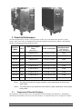
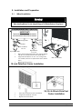
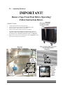
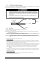
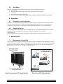
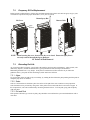
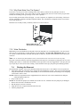
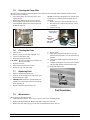
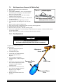
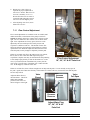
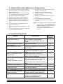
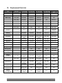
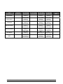
Table of Contents
Section
Description
Page
1.
2.
3.
WARNINGS ..........................................................................................................................................................3
LIMITED WARRANTY .......................................................................................................................................3
POLARCOOL PERFORMANCE..........................................................................................................................4
3.1
TEMPERATURE DIFFERENTIAL READINGS.......................................................................................................4
4. CONTROLS...........................................................................................................................................................5
4.1
VALVES ..........................................................................................................................................................5
4.2
18” AND 36” VARIABLE SPEED CONTROL PANEL ...........................................................................................5
4.3
SWITCHES .......................................................................................................................................................6
5. INSTALLATION AND PREPARATION.............................................................................................................7
5.1
WHEEL INSTALLATION ...................................................................................................................................7
5.2
UNPACKING POLARCOOL ...............................................................................................................................8
5.3
230 VAC /50 HZ WIRING DIAGRAM ...............................................................................................................9
5.4
START-UP.......................................................................................................................................................9
5.5
SHUT DOWN .................................................................................................................................................10
6. OPERATION .......................................................................................................................................................10
6.1
VENTILATION IS VERY IMPORTANT ..............................................................................................................10
6.2
NORMAL OPERATION ...................................................................................................................................10
7. MAINTENANCE.................................................................................................................................................10
7.1
MAINTENANCE ACCESSIBILITY ....................................................................................................................10
7.2
FREQUENCY OF PAD REPLACEMENT ............................................................................................................11
7.3
EXTENDING PAD LIFE ...................................................................................................................................11
7.3.1
Algae....................................................................................................................................................11
7.3.2
Scale.....................................................................................................................................................11
7.3.3
Dirt and Dust .......................................................................................................................................11
7.3.4
Why Drain Water From The System? ..................................................................................................12
7.3.5
Water Distribution ...............................................................................................................................12
7.4
FLUSHING THE RESERVOIR ...........................................................................................................................12
7.5
CLEANING THE PUMP FILTER ........................................................................................................................13
7.6
CLEANING THE PADS ....................................................................................................................................13
7.7
REPLACING PADS .........................................................................................................................................13
7.8
WINTERIZATION ...........................................................................................................................................13
7.9
BELT INSPECTION OR REMOVAL (48” MODEL ONLY)...................................................................................14
7.10 FLOAT ADJUSTMENT ....................................................................................................................................14
7.11 FLOW CONTROL ADJUSTMENT .....................................................................................................................15
8. POLARCOOL PREVENTIVE MAINTENANCE REQUIREMENTS ..............................................................16
9. TROUBLESHOOTING GUIDE..........................................................................................................................16
10. REPLACEMENT PARTS LIST ..........................................................................................................................17
11. REPLACEMENT PARTS FOR DIRECT DRIVE – VARIABLE SPEED 18" POLARCOOL (2007 AND
OLDER MODELS)..............................................................................................................................................19
12. REPLACEMENT PARTS FOR DIRECT DRIVE – VARIABLE SPEED 18" POLARCOOL (2008 AND
NEWER MODELS) .............................................................................................................................................20
13. REPLACEMENT PARTS FOR DIRECT DRIVE – VARIABLE SPEED 24" POLARCOOL .........................21
14. REPLACEMENT PARTS FOR DIRECT DRIVE – VARIABLE SPEED 36" POLARCOOL (2007 AND
OLDER MODELS)..............................................................................................................................................22
15. REPLACEMENT PARTS FOR DIRECT DRIVE – VARIABLE SPEED 36" POLARCOOL (2008 AND
NEWER MODELS) .............................................................................................................................................23
16. REPLACEMENT PARTS FOR DIRECT DRIVE – SINGLE SPEED 36" POLARCOOL ...............................24
17. REPLACEMENT PARTS FOR BELT DRIVE – SINGLE SPEED 48" POLARCOOL....................................25
Manual No. 4801-5035 Rev 2-09
1. Warnings
! WARNING
•
Whenever water and electricity are combined in the same enclosed environment the
possibility of electric shock exists. This unit must only be plugged into a three conductor,
grounded GFI (Ground Fault Interrupt), power source. Do not open the unit with power
applied to the unit. Do not place the unit on a slope or where it can accidentally fall or
roll into water.
•
Wiring And Connections Must Comply With All National And Local Electrical Codes.
•
Installation By Qualified Electrician Required!
! WARNING
•
Hazardous rotating fan blade. Do not place fingers, arms, or other appendages into the
path of the blade, or operate the machine without the guards in place.
•
Use Caution When Handling Sharp Metal.
! WARNING
Once per month, inspect the internals of the PolarCool for signs of electrical insulation
breakdown. Check the seal at the motor, as any holes may allow water to come in contact with
open electrical circuits.
2. Limited Warranty
All products are warranted to be free from defects in material and workmanship for a period of one year
from the date of purchase if installed and used in strict accordance with the installation instructions.
Liability is limited to the sale price of any products proved to be defective or, at manufacturer’s option, to
the replacement of such products upon their return. No products are to be returned to the manufacturer,
until there is an inspection and/or a return-goods authorization (RGA) number is issued.
All complaints should be directed first to the authorized distributor who sold the product. If satisfaction is
not obtained or the name of the distributor is not known, write the manufacturer that appears below,
directed to the attention of Customer Service Manager.
This limited warranty is expressly in lieu of any and all representations and warranties expressed or
implied, including any implied warranty of merchantability or fitness for a particular purpose. The remedy
set forth in this limited warranty shall be the exclusive remedy available to any person. No person has
authority to bind the manufacturer to any representation or warranty other than this limited warranty. The
manufacturer shall not be liable for any consequential damages resulting from the use of our products or
caused by any defect, failure or malfunction of our products (Some areas do not allow the exclusion or
limitation of incidental or consequential damages, so the above limitation or exclusion may not apply to
you.)
This warranty gives you specific legal rights and you may also have other rights that vary from area to
area.
Manual No. 4801-5035 Rev 2-09
PolarCool
Page 3 of 26
3. PolarCool Performance
The following table shows estimates of the performance of three sizes of the PolarCool Evaporative Cooling
System. These values will vary depending on the particular installation and operating conditions. Both Variable
Speed(VS) and Single Speed(SS) models are listed.
Drive
Water Consumption
Rates
(See Note 1)
Power Consumption
Typical Air
Movement Rates
(cubic feet per
minute- See Note 2)
18” VS
Direct
5 gallons per hr.
5 amps @ 115v /60hz
3,000
18” VS
Direct
5 gallons per hr.
3.5 amps @ 230v /50hz
3,000
24” VS
Direct
7 gallons per hr.
6 amps @ 115v /60hz
4,400
24” VS
Direct
7 gallons per hr.
3.5 amps @ 230v /50hz
4,400
36” VS
Direct
12 gallons per hr.
10 amps @ 115v /60hz
10,000
36” VS
Direct
12 gallons per hr.
5.5 amps @ 230v /50hz
10,000
36” SS
Direct
10 gallons per hr.
7.0 amps @ 115v /60hz
10,000
48” SS
Belt
17 gallons per hr.
11 amps @ 230v /60hz
17,500
48” SS
Belt
17 gallons per hr.
8 amps @ 230v /50hz
17,500
PolarCoo
l Model
Note 1: This estimate is under 90+ degree conditions; cooler temperatures will result in less
water usage.
Note 2: The cooling area is very dependent on the relative humidity, temperature, and the space
being cooled.
3.1
Temperature Differential Readings
The temperature drop from inlet to exit is very dependent on relative humidity and temperature. The higher the
ambient temperature and the drier the air, the greater the drop. A temperature drop of 10 to 20 degrees is common.
Manual No. 4801-5035 Rev 2-09
PolarCool
Page 4 of 26
4. Controls
New for 2008, the 18” and 36” Variable Speed PolarCool units feature a completely redesigned control panel
interface. The new control panel provides a user friendly interface with status indicator lights.
The 24” and 48” PolarCool models have two valves and two switches. Their functions are as follows:
4.1
•
•
4.2
•
•
•
•
•
•
•
Valves
Discharge Valve (24” and 48” models only) – Used when pumping out the reservoir for cleaning and
extended shutdown (Down time greater than 24 hours). Also used to implement the “bleed-off” function.
Connect a hose to this valve when pumping out the system or implementing “bleed-off” to prevent dangerous
water puddling around the fan.
Spray Bar Adjustment Valve (18”, 24”, 36”, and 48” models) – Used to adjust the water flow to the spray bar.
The valve can be opened or closed to increase or decrease the water flow to the pads. Too much water can
allow droplets or a mist to be blown out of the fan. Too little water will prevent thorough wetting of the pads
and will result in a reduction in cooling efficiency.
18” and 36” Variable Speed Control Panel
Power Indicator Light – The red Power Indicator Light is located at the bottom-center of the control panel
label and illuminates the Danger High Voltage Triangle. The Power Indicator Light remains ON constantly
while power is applied to the PolarCool unit.
Fan Control ON/OFF Button – This button is used to start and stop the fan.
+ and – Speed Control Buttons – Used to select the fan speed to any position between LO and HI. These
buttons control the fan speed only and does not turn the fan on or off..
Water Pump Control ON/OFF Button – This button is used to start and stop the water pump.
Caution: This switch should never be turned on unless there is water in the pan.
Pump ON – The green indicator PUMP ON light is ON solid when the water pump is running.
Low Water – The red indicator LOW WATER light is ON blinking when the water level is low for less than 1
minute. After the first minute, the red indicator light is ON solid.
Fill – The green indicator FILL light turns ON blinking when the water level has remained low for a constant
time of more than 1 minute. Also after the first minute of constant low water level, the water pump will
automatically turn off, the Pump ON and Fill green indicator lights will be blinking, and the Low Water red
indicator light will be ON solid.
NOTE: The water must be filled above the low level switch and remain above the switch for a minimum of 1
minute solid before the water pump will turn back On.
Manual No. 4801-5035 Rev 2-09
PolarCool
Page 5 of 26
4.3
•
Switches
Section 4.3 pertains only to the 24” Variable Speed Model and the 36” & 48” Single Speed Models.
Fan Control Switch – Used to start and stop the fan. This switch is the one on the left when looking at the bank
of switches. Note: Some models come with two speed and others with variable speed fans. Refer to the figure
below for available models and fan speeds. These models will have a two position switch to turn the fan On
and Off (36" and 48" Single-Speed Models) or a two position On/Off switch with a variable speed knob (24"
Variable Speed Model).
•
Pump Control Switch – Used to start and stop the pump, and is located on the right when looking at the bank
of switches. Caution: This switch should never be turned on unless there is water in the sump.
•
Speed Control Knob – Used to select the fan speed to any position between Low and High (24" Variable Speed
Models). This knob controls the fan speed only and does not turn the fan on or off.
24" Variable-Speed Model
Variable Speed Fan Knob
36" and 48" Single-Speed Models
Single Speed Fan Toggle Switch
4501-6085
ON
ON
OFF
OFF
FAN
CONTROL
PUMP
CONTROL
4501-0214
NOTE: The 18” & 36” Variable-Speed Models
Manufactured in 2007 and Before Included
the Variable Speed Fan Knob Assembly as
Pictured Above.
Manual No. 4801-5035 Rev 2-09
PolarCool
Page 6 of 26
5. Installation and Preparation
5.1
Wheel Installation
Warning!
PolarCool Appliance Is Heavy!
When Installing Wheels, Provide Adequate Support To Maintain Balance Of Appliance!
IMPORTANT!
Ensure the washers are placed between
the wheel bracket and the wheel channel.
Carriage Bolts
Washers
Caster
Support
Channel
Caster
Bracket
Swivel Wheels
w/Lock
Rigid Wheels
Nylon-Insert Nuts
w/o Lock
1.
Place wheel bracket against the caster support channel
with the 5/16 washers in between as shown above.
2.
Align holes and attach 5/16-18 x 3/4” carriage bolts,
5/16 washers, and 5/16-18 nylon-insert nuts as shown
above.
3.
Repeat for all four casters.
Bolt Access Holes
18 inch PolarCool Caster Installation
1.
2.
3.
Insert wheel bracket into fork lift channels.
Align holes and attach 1/4" bolt.
Repeat for all four wheels.
Manual No. 4801-5035 Rev 2-09
PolarCool
24, 36, & 48 inch PolarCool
Caster Installation
Page 7 of 26
5.2
Unpacking PolarCool
IMPORTANT!
Remove Tape From Float Before Operating!
Follow Instructions Below.
Diagram 1
INSTRUCTIONS:
1.
2.
3.
Carefully unpack PolarCool from shipping carton.
Lift Cover to gain access to pads as shown in Diagram 1 at right.
Tilt pads as shown. Remove pads to access float.
Float is securely taped to bottom of PolarCool for shipment.
USE HAND AND APPLY PRESSURE TO HOLD FLOAT IN PLACE.
CAREFULLY PEEL TAPE FROM FLOAT WITH OTHER HAND! DO
NOT BEND FLOAT ARM WHILE REMOVING TAPE! See Diagram 2.
4.
Replace pads. Look for arrows on side of pad as shown in Diagram 3. Ensure
pads are replaced with up arrow pointed UP.
Diagram 2
Float Shown Ready For Operation
Diagram 3
LOW
LEVEL
SWITCH
FLOAT
Manual No. 4801-5035 Rev 2-09
Low Level
Switch
(Only on 18”
and 36”
Variable
Speed
Models.
PUMP
PolarCool
Page 8 of 26
5.3
230 VAC /50 hz Wiring Diagram
The 230 VAC /50 hz PolarCool models are supplied with a stubbed power cord which must be wired to the specific
plug necessary to match local, state, and national electrical receptacles.
! WARNING
•
Whenever water and electricity are combined in the same enclosed environment the
possibility of electric shock exists. This unit must only be plugged into a three conductor,
grounded GFI (Ground Fault Interrupt), power source. Do not open the unit with power
applied to the unit. Do not place the unit on a slope or where it can accidentally fall or
roll into water.
•
Wiring And Connections Must Comply With All National And Local Electrical Codes.
•
Installation By Qualified Electrician Required!
Line 1
Power Cord
from
230 VAC PolarCool
5.4
Black
230 VAC
Line 2
White
Ground
Start-Up
The PolarCool is easy to prepare for operation. There are five easy steps.
1. Hook-up water hose to inlet tap.
NOTE: If desired, an optional customer supplied drain hose and cut-off valve can be attached to the drain pan
outlet beneath the PolarCool.
2. Check safety of electrical cords, and plug in unit. Caution: The system must always be plugged into a three
conductor, grounded GFI (Ground Fault Interrupt), power source.
WARNING: Do not place the unit on a slope or where the unit can accidentally fall or roll into water. The
lockable wheels provide resistance to movement although do not prevent movement or turnover.
3.
Turn on water and allow time for the reservoir to fill.
IF PADS ARE NEW:
When pads are new, their slick surface will prevent the fast water absorption that will happen with older pads.
For this reason, it is important that the first time new pads are used, to allow the pump to run for two or three
hours. This will "soak-in" the pads, and allow faster start-up later.
After soaking new pads, turn off the pump, fan, and water supply, unplug the unit, and drain the reservoir. The
reservoir can be drained using the Drain Outlet, or for 24 and 48 inch models, the Discharge Valve and pump
can be used to remove water. This eliminates chemical residues that have washed out of the new pads.
NOTE: Do not allow the pump to run without water in the reservoir. Without water, the pump may be
damaged.
Foaming can occur with new pads. If excessive foaming is experienced, repeat the procedure described above
two or three times to flush chemical residues from the pads. Reducing the water flow to the pads may also be
helpful to reduce foaming.
4.
NORMAL OPERATION :
Turn on the pump and let the water run for fifteen to twenty minutes before turning on fan.
Turn on fan and enjoy the cool air output.
Manual No. 4801-5035 Rev 2-09
PolarCool
Page 9 of 26
5.5
Shut Down
When you are finished with the PolarCool, follow these steps for shutting down the unit.
1. Turn off pump.
2. Wait ten to fifteen minutes (This will dry the pad and minimize algae growth).
3. Turn off fan.
4. Disconnect water and power to the unit.
5. If water is not disconnected, turn off water hose to PolarCool whenever PolarCool is not in use.
6. Operation
6.1
Ventilation is Very Important
Fresh air is very important for proper operation of evaporative cooling. Ventilation can be provided by air flow
from open windows and doors, or exhaust fans. Positioning the PolarCool intake close to an open door is a
common way to assure fresh air. Evaporative cooling will not function properly in a closed environment.
6.2
Normal Operation
Under normal conditions, the pump should run constantly when air is being drawn through the pads. If outside
conditions are not warm enough to run evaporative cooled air, an alternative is to run the fan
with the pump off.
Dry the pads completely each night by turning off the pump and drawing air through the pads with the fan.
7. Maintenance
7.1
Maintenance Accessibility
Since evaporative coolers require maintenance, the PolarCool has been designed to make maintenance as easy as
possible. By simply raising the rear cover, basically all critical parts are within easy reach for inspection, including
the pads, spray bar, fan belt (48” model only), pump, strainer, and water reservoir. The 36 inch Single Speed
PolarCool has a special rear cover. To open, see the Figure below.
Push Down to Lock
To open rear cover
on 36"Single Speed
Step 4
Step 3
Rotate Up
Step 2
Pull Forward
Step 1
Pull Up to Unlock
Rear Cover (except 36" Single Speed)
Manual No. 4801-5035 Rev 2-09
Rear Cover (36" Single Speed)
PolarCool
Page 10 of 26
7.2
Frequency Of Pad Replacement
PolarCool pads, produced from a cellulose base and impregnated with a plastic resin anti-rot agent, can give years
of trouble free operation with proper maintenance (3 to 5 years is typical).
Rotate Spray Bar
Lift Cover
Remove Pads
Spray
Deflector
NOTE: When lowering the cover, do not force the cover closed. Ensure the Spray Bar is
correctly centered beneath the Spray Deflector.
18" PolarCool Pad Removal
7.3
Extending Pad Life
As you use the PolarCool system, you will notice the need for good preventive maintenance. Algae growth, scale
(hard crusty deposits), and dirt accumulation are typical problems associated with poor maintenance.
Maintaining the PolarCool is very simple. It only takes a small amount of time and effort. If you follow the
guidelines below, your pads will last much longer, and be much more efficient.
7.3.1 Algae
To prevent algae, allow the pads to dry out each day, by running the fan without the pump running until the pads are
completely dry (about 15 minutes).
7.3.2 Scale
Scale is a concentration of solids that “plate” the surface of the pads if the water contains too many impurities.
Scale formation can be prevented by using water with a pH between 6 and 9 and silica levels below 150 ppm. If
this is impractical, scale can be minimized by increasing the drain-off rate. To clean pads, spray pads frequently
with water hose.
7.3.3 Dirt and Dust
If the pads are allowed to get excessively dirty, they should be removed from the system and washed down with a
water hose.
Manual No. 4801-5035 Rev 2-09
PolarCool
Page 11 of 26
7.3.4 Why Drain Water From The System?
If you have ever left a pot of coffee warming on the coffee maker you know the two principles at work in
evaporative cooling systems. First, as the coffee sits on the warming plate, the level of water in the pot goes down.
Second, the remaining coffee gets stronger as the water evaporates.
In your cooling system, these effects still apply. As water evaporates, no impurities are carried along. This leaves
all sorts of minerals, chemicals, and other impurities behind. The concentration of impurities in the reservoir and
system will quickly rise.
Drain the reservoir daily in dusty conditions, and twice a week in clean air.
Drain Outlet w/Cap
18 inch PolarCool Model Shown
7.3.5 Water Distribution
Maintaining even water distribution to the pads is the most important way of extending pad life. If an area of pad
does not receive enough water, cooling efficiency will be degraded. The Spray Bar Adjustment Valve (18”, 24”,
36”, and 48” models) should be increased until the pads are fully wet, but not to the extent that a mist is blown out
of the fan.
Note:
The 18” model’s Spray Bar Adjustment Valve is located inside the unit on the lower-side of the water pump.
Dry spots or streaks can also be caused by clogged holes in the spray bar. Investigate by raising the rear cover and
running a pipe cleaner, or small dowel into the holes in the spray bar to clear any clogged holes. The spray bar end
cap or caps may be removed for easier cleaning. Ensure the holes in the spray bar point upward during operation.
7.4
Flushing the Reservoir
The pads and the complete water system should be flushed out at least once a week and the reservoir wiped clean.
1. Turn off the pump, fan, and water source, unplug the unit and drain the reservoir. The reservoir can be drained
using the Drain Outlet for 18 and 36 inch models, or for 24 and 48 inch models, the Discharge Valve and pump
can be used to remove water.
NOTE: If desired, an optional customer supplied drain hose and cut-off valve can be attached to the drain pan
outlet beneath the PolarCool.
2. Wipe out the reservoir.
NOTE: Do not allow the pump to run without water in the reservoir. Without water, the pump may be damaged.
3. Restore the water source and fill the reservoir.
4. Run the pump for at least 15 minutes.
5. Pump the reservoir out again and refill with fresh water.
6. Start the pump and fan.
Manual No. 4801-5035 Rev 2-09
PolarCool
Page 12 of 26
7.5
Cleaning the Pump Filter
The water pump includes a removable plastic filter on the bottom of the pump which should be cleaned weekly
when the reservoir is flushed.
1. Turn off the pump, fan, and water source, and
NOTE: Do not allow the pump to run without water
unplug the unit.
in the reservoir. Without water, the pump may be
2. Remove the pump from the reservoir, remove
damaged.
and clean the screen on the bottom of the motor,
3. Restore the water source and fill the reservoir.
and reinstall the pump in the same location and
4. Reconnect power and run the pump for at least
method as removed.
15 minutes.
5. Turn the fan ON.
Pump
(18 inch PolarCool
Model Shown)
Spray
Adjustment
Valve
Float and Pump
(2007 models
and earlier)
Removable
Screen
(48 inch PolarCool Model Shown)
7.6
Cleaning the Pads
1. Turn off fans.
2. Remove screws on each side of hinged cover.
3. Lift cover and remove pads.
4. Hose down each side of pads.
CAUTION: Do Not Use High Pressure Washer To
Hose Down Pads!
5. Drain the reservoir.
6. Shut off pump and clean out strainer.
7. Refill reservoir with clean water.
7.7
(All Models)
8.
9.
Replace pads.
Turn on the pump to run fresh water over the
pads for about 20 minutes. Use as much water as
possible.
10. Gently hose stubborn deposits from the face of
the pads.
11. Completely empty the reservoir to remove all the
old algae and dirt that will rinse off the pads.
12. Refill with clean water.
Replacing Pads
1.
Remove old pads from PolarCool.
2.
Look for Air Flow Diagram on side of new pad.
Refer to diagram at right.
3.
IMPORTANT! Install new pad into PolarCool
with Air Flow in direction of arrow and with up
arrow pointing UP.
4.
Replace all pads as described in step 3.
Pad Orientation
7.8
Winterization
When storing for extended periods:
1. Flush and clean reservoir. Never leave water in reservoir for extended periods.
2.
Remove and backwash pads. Remove any debris or deposits from pad.
3.
Remove the drain outlet cap to prevent water accumulation inside the reservoir.
Manual No. 4801-5035 Rev 2-09
PolarCool
Page 13 of 26
7.9
Belt Inspection or Removal (48” Model Only)
1.
2.
3.
Disconnect all electrical power to PolarCool!
Diagram A To open belt, twist and
Remove pads.
push tabs through holes.
TEST FOR LOOSE BELT: Press on belt with finger
about halfway between pulleys. Belt should deflect
about 3/4" if correctly fitted.
4. To remove belt, slowly rotate belt while carefully
rolling belt off of prop pulley.
5. After removing belt, turn belt inside out. Links should
NOTE: Section of belt shown inside out.
resemble Diagram A.
Shaded region indicates 1 link of belt.
6. Flex belt to form a short, tight loop at one end.
7. Twist and unlock tabs holding link. This will open
belt.
8. Remove links as required to tighten belt.
9. After removing link(s), reattach belt together by locking tabs through holes.
10. Turn belt to place tabs to inside of belt.
11. Hook belt onto motor pulley. Roll belt onto Prop pulley.
12. After belt is installed, press on belt with finger about halfway between pulleys. Belt should deflect about
3/4" if correctly fitted.
NOTE: Make sure arrows on belt are pointing in direction of prop rotation.
7.10
Float Adjustment
Important!
Float Is Preset By Manufacturer
And Should Not Require Adjustment Under Normal Circumstances!
If adjustment is required, perform the
following steps:
1.
Disconnect all electrical power to
PolarCool appliance!
2.
Carefully remove pads.
3.
Locate float valve inside PolarCool.
Refer to Replacement Parts
Diagram.
4.
Use a screwdriver and loosen
adjustment screw as shown in figure
at right.
5.
To decrease water level in reservoir,
move float arm downward as shown
in diagram at right. Retighten
adjustment screw.
6.
To increase water level in reservoir,
move float arm upward as shown in
diagram at right. Retighten
adjustment screw.
7.
Adjustment
Screw
Increase Water
Level
Decrease Water
Level
Replace pads. Return PolarCool to
operation.
Manual No. 4801-5035 Rev 2-09
Float Arm
PolarCool
Page 14 of 26
8.
9.
Repeat steps 1 thru 7 above as
required for proper adjustment of
water level. NOTE: Water level in
reservoir is normally 2-1/4" ± 1".
Do not allow the reservoir water to
contact the pads when the reservoir
water level is at the highest point.
Flow
Control
Valve
After adjusting water level, return
PolarCool to service.
7.11
Flow Control Adjustment
Flow control adjustments are available on the 18″ model (2007
models and earlier) on the bottom of the pump as shown in
Section 7.5 and also at the Flow Control Valve as shown to the
right. The 36″ model has a flow control valve as shown to the
right. Flow adjustments are factory preset, however can be
adjusted by the user based upon local water pressure and
evaporative conditions at the site. The amount of water flow
affects the efficiency and operation of the PolarCool. During
operation the flow should be adjusted so that sufficient water
soaks the pads, but only enough to completely soak the pads.
If there is too much water flow, the pads become over-soaked,
that is, there is more water flow than required for proper
evaporation. Surplus water may be sucked into the fan producing
a water droplet spray directly in front of the PolarCool. I some
cases, if you stand in front of the PolarCool you may feel the
water spray! The efficiency of the Polar cool is reduced in this
case. If this happens, reduce the water flow.
Pump
Flow Control Adjustment
18", 24", 36" & 48" PolarCool
If there is too little flow, there will not enough water to fully soak the pads. You can actually see dry spots in
the pads. Again, this reduces the efficiency of the PolarCool. If this is the case, increase the flow until the pads
become fully soaked.
Adjust the Water Flow as
described above. The FULL
OPEN and CLOSED
positions of the Valve are
shown in figures at the right.
Valve
Closed
Increase
Pressure
Valve
Full Open
Decrease
Pressure
Adjust Water Flow
18", 24", 36" & 48"
PolarCool
Manual No. 4801-5035 Rev 2-09
PolarCool
Page 15 of 26
8. PolarCool Preventive Maintenance Requirements
•
•
•
•
•
•
•
•
Flush the system at least once per week and wipe
the reservoir clean to prevent damage to the unit.
Refer to Section 7.4.
Allow the pads to dry out each day, by running
the fan without the pump running until the pads
are completely dry (about 15 minutes).
Drain the system during extended shutdowns.
Disinfect the whole system once per quarter.
Routinely inspect fan belt (48” model only) for
looseness and inspect spray bar for debris in
holes.
Turn off water hose to PolarCool whenever
PolarCool is not in use.
Have the right amount of water running over the
pad.
If power cord extension is necessary, ensure that
you use 12 AWG or larger wire.
•
•
•
•
•
•
Ensure that air is not limited or restricted from
entering or exiting the unit.
Identify and correct leaks in the system.
Excessive dust, fumes, and harsh cleaners,
should be avoided.
Do not use in closed environment. Fresh air is
necessity.
Do not add chlorine or bleach to water.
Never use phosphate based water treatment
chemicals.
NOTE: After running 100 hours, inspect belt tension
(48” model only). Refer to Belt Removal
section 7.9, step 11 for belt tension guide.
If belt requires tightening, follow
instructions in the same section for belt
removal.
9. Troubleshooting Guide
Problem
Check/Action
Reference
Section
Swivel casters will not turn.
Check installation of caster hardware.
Hardware must be in the proper order and
location.
5.1
First time using a NEW PolarCool Water overflows
Remove tape from float.
5.2
Water is splashing off of pads
Pads may be in backwards; Check Flow chart
on side of pad.
7.7
Water spraying out from cover.
Ensure the holes in the spray bar point
upward into the spray deflector. (Vertical
Spray).
Water is not spraying out of ANY
spray bar holes.
Ensure pump switch is ON; Check for
sufficient water in reservoir; Check screen on
bottom of pump for obstructions.
Water is not spraying out of SOME
spray bar holes.
Adjust spray using the Spray Bar Adjustment
Valve, the spray bar should be cleaned, OR
the pump screen should be cleaned.
Excessive dry streaks in the pads.
7.3.5
7.5
4.1 and 7.3.5
Remove spray bar and clean the bar and all
holes.
Existing Unit – Water overflows
Adjust float valve to a lower position.
Fan motor doesn’t turn ON and no
sound from the motor.
Check PolarCool Switches, power cord, GFCI
outlet, and circuit breaker.
48” Fan blade doesn’t turn or slips.
Check for broken or loose fan belt. (48” ONLY)
Motor overheats and shuts off then
restarts minutes later.
Extension cord gauge is too small or the air
passage is blocked or partially obstructed.
Pump does not work.
Check for low water-level and low-level switch.
7.10
7.9
0
4.2 & 5.2
(18” and 36” Variable-Speed models
manufactured in 2008 and later)
Manual No. 4801-5035 Rev 2-09
PolarCool
Page 16 of 26
10.
Replacement Parts List
18" Vari Spd
24" Vari Spd
36" Vari Spd
36" Sgle Spd
48" Sgle
Spd
Cooling Pads
0050-6503
0050-6502
0050-6501
0050-7601
0050-6500
Complete Pad Set
2 Required
3 Required
5 Required
4 Required
6 Required
120v / 60Hz
6422-0610
6422-0612
6422-0615
6422-0614
N/A
230v / 50Hz
6422-0611
6422-0613
6422-0616
N/A
6422-0617
230v / 60Hz
N/A
N/A
N/A
N/A
6422-0617
120v / 60Hz
3017-5018
3017-5018
3017-5600
3017-2271
N/A
230v / 50Hz
3017-5018
3017-5018
3017-5602
N/A
3017-3081
230v / 60Hz
N/A
N/A
N/A
N/A
3017-3081
Fan Belt
N/A
N/A
N/A
N/A
Fan Prop
6403-5610
6403-6000
6403-5600
6403-6112
6403-6111
Float Valve
1009-0107
3001-2862
1009-0107
1009-0107
3001-2862
1009-0107
1009-0107
Fan Switch
(2007 and older
models)
3001-2862
(2007 and older
models)
3001-2865
3001-2865
Front Mesh Guard
0011-7100
0011-7005
0011-7007
0011-7007
0011-7006
Spray Bar
6422-0570
6422-0532
6422-0531
6422-0206
6422-0530
230v / 50Hz
N/A
N/A
N/A
N/A
1011-2647
230v / 60Hz
N/A
N/A
N/A
N/A
1011-2650
Pulley (Fan Prop)
N/A
N/A
N/A
N/A
1011-0100
Bearing Assy.
N/A
N/A
N/A
N/A
1016-0100
Hose Adapter
Fitting
1021-3000
1021-3000
1021-3000
1021-3000
1021-3000
Fan Shaft
N/A
N/A
N/A
N/A
0411-4535
6407-1540
(2007 and older
models)
N/A
N/A
6407-1558
(2007 and older
models)
N/A
N/A
3001-2862
(2007 and older
models)
3001-2865
3001-2865
1903-6000
(2007 and older
models)
N/A
N/A
N/A
(2008 and later
models)
N/A
N/A
N/A
(2008 and later
models)
N/A
N/A
Part
Water Pump
Fan Motor
Pulley (motor)
PCB175
Circuit Board
Volts/Hz
(2007 and older
models)
230v / 50Hz
(2007 and older
models)
6407-1556
6407-1544
3001-2862
Pump Switch
(2007 and older
models)
(2007 and older
models)
Low-Level
Switch/Harness
(2008 and later
models)
PCB189
Circuit Board
3001-2862
1903-6000
1903-6000
Vari-Speed
Switch/Harness
3001-0050
3001-0050
6407-1615
6407-1610
120v / 60Hz
Manual No. 4801-5035 Rev 2-09
(2008 and later
models)
(55-1/2")
(141 cm)
6407-1540
6407-1542
120v / 60Hz
1022-2998
PolarCool
Page 17 of 26
Part
Volts/Hz
Control Plate
Control Panel
Control Box
3 Pos Connector
2 Pos Connector
Level Switch
Nut
Manual No. 4801-5035 Rev 2-09
18" Vari Spd
24" Vari Spd
6407-5136
(2008 and
newer models)
6407-1610
(2008 and
newer models)
1028-3500
(2008 and
newer models)
3006-5082
(2008 and
newer models)
3006-5107
(2008 and
newer models)
3001-0050
(2008 and
newer models)
10010110(2008 and
newer models)
PolarCool
36" Vari Spd
36" Sgle Spd
6407-5137
(2008 and
newer models)
6407-1615
(2008 and
newer models)
1028-3500
(2008 and
newer models)
3006-5082
(2008 and
newer models)
3006-5108
(2008 and
newer models)
30010050(2008 and
newer models)
1001-0110
(2008 and
newer models)
6407-5137
(2008 and
newer models)
6407-1615
(2008 and
newer models)
1028-3500
(2008 and
newer models)
3006-5082
(2008 and
newer models)
30065107(2008 and
newer models)
30010050(2008 and
newer models)
1001-0110
(2008 and
newer models)
48" Sgle
Spd
Page 18 of 26
Replacement Parts for Direct Drive – Variable Speed 18" PolarCool
(2007 and Older Models)
Circuit
Board
Motor
Float
Valve
Assy.
Pads
Drain
Outlet
Fan Prop
Pump
Guard
11.
Manual No. 4801-5035 Rev 2-09
PolarCool
Page 19 of 26
Replacement Parts for Direct Drive – Variable Speed 18" PolarCool
(2008 and Newer Models)
Allen
Wrench
Circuit
Board
Control
Cover
Motor
Float
Valve
Assy.
Pads
Drain
Outlet
Fan Prop
Pump
Guard
12.
Manual No. 4801-5035 Rev 2-09
PolarCool
Page 20 of 26
Motor
Manual No. 4801-5035 Rev 2-09
Pads
Switch/Harnes
s
Variable Speed
Fan/Pump Switches
(also available separately)
Float
Fan Prop
Circui
t
Pump
Spray Bar
Front Mesh Guard
13.
Replacement Parts for Direct Drive – Variable Speed 24" PolarCool
PolarCool
Page 21 of 26
Fan/Pump Switches
Manual No. 4801-5035 Rev 2-09
Motor
Switch/Harness
Variable Speed
Assembly
Pads
(also available separately)
Float
Fan Prop
Circuit Board
Spray Bar
Pump
Front Mesh Guard
14.
Replacement Parts for Direct Drive – Variable Speed 36" PolarCool
(2007 and Older Models)
PolarCool
Page 22 of 26
Replacement Parts for Direct Drive – Variable Speed 36" PolarCool
(2008 and Newer Models)
Circuit
Board
Motor
Pads
Float
Spray Bar
Pump
Allen
Wrench
Front Mesh Guard
15.
Manual No. 4801-5035 Rev 2-09
PolarCool
Page 23 of 26
Replacement Parts for Direct Drive – Single Speed 36" PolarCool
Motor
Fan Prop
Pads
Float
Control Box
Spray Bar
Pump
Front Mesh Guard
16.
Manual No. 4801-5035 Rev 2-09
PolarCool
Page 24 of 26
Manual No. 4801-5035 Rev 2-09
Motor
Pulley
PolarCool
Fan Belt
Pads
Pulley Shaft
Prop Pulley
Motor
Pillow Block Bearings
Float
Fan Prop
Spray Bar
Pump 50/60 Hz
Front Mesh Guard
17.
Replacement Parts for Belt Drive – Single Speed 48" PolarCool
Page 25 of 26