1
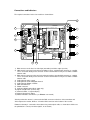
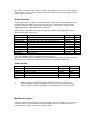
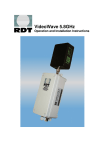
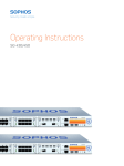
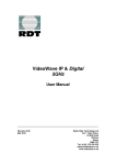
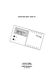
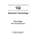
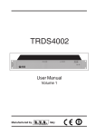
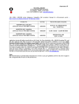
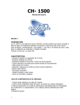
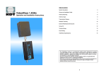
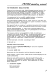
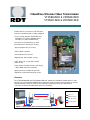
VideoWave Wireless Video Transmission
VTX5800SED & VRX5800SED
VTX5801SED & VRX5801SED
Enables wireless connection of PTZ and Dome
Cameras to monitoring and recording equipment
Licence exempt operation (R&TTE Directive)
VideoWave uses 5725 to 5875GHz band
Telemetry uses 400 to 470MHz band
6 Channels (3 non interfering), for Video
64 Channels for Telemetry (15 UK spec)
Signal strength meter (on receiver)
240V ac Mains operation
IP67 weatherproof enclosures
Digital (alarm) channel (5801 version)
Audio channel, or second alarm channel
(5801 version)
Patch antenna included for Video (1Km range)
½ Wave Whip antenna for Telemetry
Optional antennas available for specialist
applications and extended range up to 3km.
Overview
The VTX/VRX5800SED and VTX/VRX5801SED units combine the VideoWave 5.8GHz wireless video
transmission system with the RM9600 radio modem transceiver to provide remote operation of cameras
with full telemetry control. The units are housed in IP67 weatherproof enclosures with antenna
connectors on the top and cable glands in the base for wiring
Key:
Video co-ax
RS485 twisted pair
VRX5800SED
VTX5800SED
Radio signal (video)
Radio signal (data)
Figure 1. Point to point video & telemetry transmission
Connections and Indicators
The required connections for the four models are shown below: -
8
13
9
1
+
+
+
3
+
+
6
+
+
10
+
5
E
N
L
PSU
11
12
MAINS INPUT
2
4
7
1) BNC connector on the base for video input (transmitter) and video output (receiver)
2) SMA antenna connector (for the video transmitter/receiver). Standard patch antennas as supplied,
can be connected directly to this connector or other external antennas may be used with a suitable
antenna cable
3) BNC antenna connector on the top for the telemetry modem. Standard whip antennas as supplied,
can be connected directly to this connector or other external antennas may be used with a suitable
antenna cable
4) Cable gland for mains supply
5) Cable gland for audio and digital channels
6) Cable gland for RS485 or RS232
7) Mains terminal block
8) RS485 connector
9) Audio and digital terminal block (5801 only)
10) Signal strength meter (receiver only)
11) Channel number, 7-segment display
12) Channel change push button
13) Modem indicators and switches (see RM9600 user manual)
Video input from the camera is connected to the BNC connector on the base of the transmitter unit.
Video output to the monitor, DVR etc. is from the BNC connector on the bottom of the receiver.
RS485 for telemetry is connected to the modem using a twisted pair cable, as shown above. Make sure
the polarization is correct (from left to right B-, A+ and earth)
There is a SMA antenna connector on the top of each unit for the video antenna. The patch antenna
supplied may be attached directly to this connector, or if required, the antenna can be remotely mounted
and connected with a suitable cable. Remember that at this frequency antenna cable lengths should be
kept to a minimum to avoid losses in output power. There is also a range of other higher gain antennas
available for other applications and to extend the range.
The BNC connector is for the telemetry antenna. The whip antenna supplied will be suitable for most
applications, but other antennas for longer range are available.
After installation is complete, make sure that the cable glands are tightened and the antenna and BNC
connections are completely sealed against the weather with self amalgamating tape.
On the 5801 versions there is also the option of audio and digital alarm channels. The alarm channel is
ideal for applications that require remote alarm signalling or control of external devices (e.g. access
control, lighting etc.)
The inputs for the digital alarm channels on the transmitter are volt free contacts. On the receiver there
are corresponding changeover relay outputs with contact rating 1A @ 30V dc
The audio input on the transmitter is 1 V p-p into 100KΩ unbalanced. The receiver output is 1 V p-p (for
a 1 V p-p input) with a frequency response of 50Hz to 15KHz.
Note that the audio channel can be linked out and used as a second digital alarm channel. This is link
selectable as shown in the above diagram, position 10.
These connections should be wired through the second cable gland and connected to the terminal block
as indicated on the PCB.
Installation and Operation
The antenna should be positioned as high as possible and there should be a good clear line-of-sight
between the TX and RX antennas. If possible, it is best to mount the units close to the antennas to keep
cable lengths as short as possible. If the antenna is remotely mounted, then ensure a good quality lowloss cable is used. It may be necessary to use a higher gain antenna to compensate for losses in the
cable. See below.
Once the transmitter is in position, connect power and connect the video input from the camera. Remove
the lid of the transmitter and check that the channel indicator 7 segment display is on. This acts as a
power-on LED. Make a note of the channel indicated as the receiver will need to be set to the same
channel. On the modem, the first 2 red supply LEDs should be on and the second, RX yellow LED. If
this is OK, connect the RS485 twisted pair.
Repeat the above installation procedure for the receiver. With the lid removed, check that the channel is
set correctly. It can be changed with the channel change button below the display. The signal strength
meter will indicate the signal strength being received from the transmitter. It may be necessary to adjust
the position or angle of the antenna to obtain maximum signal strength.
The signal strength meter has 6 LED’s, 2 red, 1 orange and 3 green. Red indicates that there is a weak
signal. Orange is the threshold point and green indicates an acceptable working level. Adjust antenna
positioning and angles to obtain the maximum signal strength but it should be a minimum of 1 green LED
solidly lit for correct operation. On the modem, the three LEDs should be on, the first 2 red LEDs and the
second RX yellow.
Connect the monitor, DVR etc to the BNC video output and connect the RS485 twisted pair to the
modem. If the received picture shows any sign of interference, turn off the transmitter and check the
signal strength meter on the receiver. There should be no activity on the LED’s and the monitor should
show no pattern or ghosting. If required, try selecting another channel, there are 6 channels available.
Check that the telemetry control is working. If there is any problem, it may be necessary to change the
modem settings. See the separate modem user manual for information on setting the channel, power
and baud rate of the modem.
Antenna Selection
The VideoWave units are supplied as standard with a pair of patch antennas, ANT5605, which can be
mounted directly to the SMA connector on the top of the units. These antennas may be remotely
mounted if required, to gain extra height and connected using a suitable cable. The modems are
supplied with a pair of ½ Wave Whip antennas, ANT0006
Other antennas are available to extend the coverage range. Note that these higher gain antennas
should be used on the receiver only.
Receive antenna
ANT5803
ANT5805
ANT5805-CAB
ANT5808-CAB
ANT5810-CAB
ANT5820-CAB
ANT5828-CAB
Telemetry
ANT0008-CAB
ANT0009-8
Description
Whip, Omni-directional
5dB gain Patch (supplied as standard)
5dB gain Patch with 1.5mtr cable and mounting clips
8dB gain Dipole, omni-directional with 1.5mtr cable
10dB gain Panel with 1.5mtr cable
20dB gain Panel with 1.5mtr cable
28dB gain Parabolic Dish with 1.5 mtr cable
Connector
SMA male
SMA male
SMA male
‘N’ female
SMA male
‘N’ female
‘N’ female
Range
500mtr
1Km
1Km
1Km
1.4Km
3Km
4Km
Dipole with 3mtr cable
8 Element Yagi
‘N’ female
‘N’ female
3Km
4Km
Note: The VideoWave unit has a SMA female antenna connector.
ANT5603 and ANT5605 may be fitted directly to the VideoWave without a cable. All other antennas are
designed for remote wall or pole mounting and should be connected with a suitable cable.
Cable Selection
Cable No
CAB0001-3
* see note 2
CAB0001-30
CAB2267
CAB2268
Description
‘N’ male to ‘N’ male
Type
LMR400
Length
3Mtrs
‘N’ male to ‘N’ male
SMA male to ‘N’ female
BNC male to ‘N’ female
LMR400
UR43
URM43
30Mtrs
600mm
600mm
Notes:
1
2
CAB0001 is a heavy duty high quality cable available in lengths from 3 to 30 metres.
Because CAB0001 is fairly stiff, a CAB2267 may be used as a short flexible cable tail to
connect the heavy cable to the VideoWave unit and CAB2268 to connect to the modem.
Multi-Camera Systems
Using the 3 non-interfering channels it is possible to install 3 cameras on the same site. In some cases,
it may be possible to use all 6 available channels depending on the local conditions and distances
between antennas. Figure 2 below shows a typical example.
It is also possible to use the 5.8GHz system in conjunction with the 2.4GHz and 1.4GHz systems to give
an increased number of channels. See separate data sheets for 1.4GHz and 2.4GHz.
VTX5800SED
VRX5800SE
VTX5800SED
VRX5800SED
VTX5800SED
VRX5800SE
To monitor &
control equipment
Wireless Video
Wireless Telemetry
Figure 2. Multi camera configuration (point to multi-point telemetry)
)transmission
Telemetry
For telemetry systems that would usually require a dedicated cabled link to each camera, (e.g. as used
with RS232 type telemetry, or co-axial telemetry with twisted pair adapters), VTX5800SED and
VRX5800SED units may be used to duplicate this in wireless form, providing dedicated video and
telemetry radio links to each camera. This type of system requires a different Rf channel to be selected
for each telemetry link.
For telemetry systems that have addressable cameras operating on an RS485 multi-drop, (e.g. daisy
chained twisted pair), the VideoWave units may be configured as illustrated in figure 2 above.
A three-camera system requires a VTX5800SED combined video transmitter and radio modem unit at
each camera. It will require three video receivers but only one radio modem that can broadcast the
telemetry signal to all three cameras. This can be achieved using one combined video and data unit,
VRX5800SED and two video only units VRX5800SE. Please refer to the separate RDT data sheet for
details of the VRX5800SE VideoWave units, if required. When used in this configuration, all radio
modems in the system should be set to the same channel. This system configuration offers a cost
effective solution to wireless telemetry transmission as only one radio modem is used at the base
location.
SPECIFICATION
VideoWave
General
Radio
Video Input:
Video Output:
Operating Voltage:
Protection:
Power consumption @ 240V ac
Transmitter:
Receiver:
Antenna Connector:
Power connector:
Indicators
Channel / ON:
Signal strength (receiver):
1V p-p into 75ohm BNC
1V p-p into 75ohm BNC
240V ac
Reverse Polarity
Frequency range:
RF Power output:
Local oscillator:
Modulation type:
Modulation Bandwidth:
5725 to 5875MHz
25mW ERP
PLL synthesised
FM
4.5MHz
Adj. Channel rejection
RSSI threshold level
-70dB
-105dBm at 16K
-110 dBm at 8K
16Kbps
GMSK
150 to 19.2 Kbaud
Odd, Even, None
1W
2.6W
50ohm SMA (female)
Screw terminal
7 Segment display
LED bar graph
Radio Modem
Frequency range
Channel spacing
No of channels
Transmitter:
RF Power output
Adj. Channel power
Freq. Tolerance
FM deviation
Receiver:
RF sensitivity
Intermodulation
406-470MHz*
25KHz
32
50-500mW (in 4 steps)
-37dBm
+/- 1KHz
+/- 3.5KHz
-110dBm for 10 BER
-70dB
Max bit rate
Modulation
Interface baud rate
Parity
Power consumption at 240V
Transmitter at 500mW
Receiver
7.2W
4.2W
* UK Specification is 15 channels 458.525 to 458.925MHz
Mechanical
Dimensions
Height*
Width
Depth
255mm
180mm
80mm
Weight
Enclosure
Mounting
Operating temperature
1.8Kg
Polycarbonate IP67
4 x 7mm dia holes
Spacing 238.5 x 163.5
-10 to +55 degrees C
* Excluding connectors and cable glands
Equipment conforms to the R&TTE Directive 1999/5/EC
Radio Data Technology Limited
10-11 Taber Place Crittall Road Witham Essex CM8 3YP England
Telephone: 01376 501255 Fax: 01376 501312
International Tel: +44 1376 501255 Fax: +44 1376 501312
URL: www.radiodata.co.uk Email: [email protected]
A member of the CML Microsystems Plc group