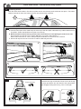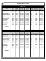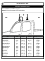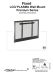
1
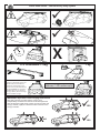
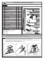
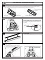
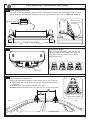
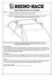
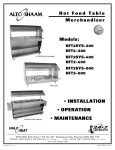
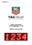
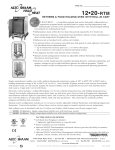
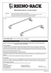
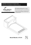
Rhino 2500 Series - Two Bar Heavy Duty System.
Important:
Please refer to your fitting instruction to ensure that the roof racks are installed in the correct locations.
Check the contents of kit before commencing fitment and report any discrepancies.
Place these instructions in the vehicle’s glove box after installation is complete.
Maximum carrying capacity: 75kg (165lbs) evenly distributed over crossbars. Please refer to your vehicle
manufacturershandbookandDKSpecificationsheetformaximumroofloading.
Alwaysusethelowerofthetwofigures.
Recommendations:
It is essential that all bolt connections be checked after driving a short distance when you first install your crossbars. Bolt connections should be checked again at regular intervals (probably once a week is enough, depending on road conditions, usage,
loads and distances travelled). You should also check the crossbars each time they are refitted. Make sure to fasten your load
securely. Please ensure that all loads are evenly distributed and that the centre of gravity is kept as low as possible.
Use only non-stretch fastening ropes or straps.
Load Ratings
When these roof racks are to be used on a vehicle that is driven off sealed roads, the manufacturer maximum roof load rating (to
be found in the vehicles User Manual) should be halved. For example, if the vehicles maximum roof load rating is 70kgs (subtract 5kg - weight of crossbar and legs), these racks, when fitted to this vehicle should have no more than 35kgs loaded on them
Caution:
The handling characteristics of the vehicle changes when you transport a load on the roof. For safety reasons we recommend
you exercise extreme care when transporting wind-resistant loads. Special consideration must be taken into account when cornering and braking.Please remove crossbars when putting vehicle through an automatic car wash.
Note for Dealers and Fitters:
It is your responsibility to ensure instructions are given to the end user or client.
Rhino 2500 Series - Two Bar Heavy Duty System
ü
ü
!
!
!
X
km/h
? kg
2 x Crossbars = 5kg
When these roof racks are to be
used on a vehicle that is driven off
sealed roads, the manufacturer
maximum roof load rating (to be
found in the vehicles User Manual)
should be halved. Do not forget to
subtract 5kg from your maximum
carrying capacity due to the weight
of the crossbars and legs.
70kg load rating
(Urban road)
WARNING! Important Load Carrying Instructions
With utility vehicles, the cabin and the canopy move
independently. Roofracks and vehicle can be damaged if the
item transported is rigidly fixed at points on both the cabin and
canopy. Instead, rigidly fix to either the cabin roofracks or the
canopy roofracks.
X
NO
=
35 kg load rating
(Off road - 70kg / 2)
ü
YES
ü
YES
Rhino 2500 Series - Two Bar Heavy Duty System
Parts List CarryingCapacity:RefertoDKspecificationsheetformaximumcarryingcapacityofyourparticularvehicle.
Item Component Name
Qty
Part No.
1
Rubber Buffer Strip
2
2
Heavy Duty Cross Bar
2
3
M8 Pivot Nut
4
N047
4
M8 x 50mm Security Bolt
4
B154
5
End Cap
4
M002
6
Heavy Duty Cross Bar Adaptor
4
M315
7
Leg
4
M310
8
Leg Cover Plate
4
M324
9
M6 Channel Nut
4
N002
10
M6 Flat Washer
4
W031
11
M6 Spring Washer
4
W004
12
M6 x 25mm Security Screw
4
B137
13
Front Cover
4
M312
12
14
Front Cover Key
2
M314
13
15
Foot Plate
4
M311
14
16
Security Allen Key
1
SecKey-L
17
Leg Location Decals
4
S365
18
Arrow Positioning Decals
4
S364
19
Fitting Instruction
1
RR244
Tools Required:
Security Allen key, provided in kit.
Tape measure.
Rubber mallet.
1
2
3
4
5
6
7
8
9
10
11
15
16
17
Pad & clamp kit
available separately
18
NOTE: RefertotheDKkitspecificationsheetforcorrectplacement(Front & Rear, Left & Right) of the foot plate, rubber
pad and metal strap. Also refer for sizes to cut the bar measurement strips.
1
Attach hardware:
a. Attach the heavy duty cross bar adaptor onto top of the leg. Push to snap in place.
b. Locate the M6 x 25mm security screw, spring washer and flat washer through top of the leg and fasten to
the M6 channel nut. Do not tighten at this stage.
c. Make sure the M8 pivot is correctly located as shown below.
a.
b.
c.
Angled face of pivot
nut faces out.
Rhino 2500 Series - Two Bar Heavy Duty System
2
Attach pad to foot plate.
Clip the rubber pad onto the foot plate. Pad centre tube and end tabs must fully locate into the foot plate.
Note: Certain rubber pad sets have a DK supplement sheet to show correct orientation.
Centre tube pushes
through.
Centre tube.
End tabs.
End tabs clip in.
3
Attach foot plate to leg.
Clip the foot plate onto base of the leg with the arrow
facing In or Out according to your vehicle listed in the
DK specification sheet. Diagram at left shows arrow
facing Out.
FRONT Cross Bar
VEHICLE
Sample Vehicle
DKPad
spec sheet.
Clamp
Build
Date
FRONT
BAR
Pad
OSF
2005 on
1180mm
M415
NSF
OSF
Clamp
NSF
M415
SUB0172
SUB0172
Foot Plate Measurement
Arrow Dir. Strip length
OUT
108mm
HD bar
Dist. ‘X’
894mm
example only.
4
5
Crossbar rubber:
Push the cross bar rubber buffer strip into top of the bar.
Attach cross bar:
a. Locate leg with channel nut into cross bar.
b. Turn to locate the channel nut to sit across the bar.
a.
b.
Channel nut must
sit across the bar.
Rhino 2500 Series - Two Bar Heavy Duty System
6
Measurement between legs:
Accurately measure between the legs to set the correct distance. Refer to DK specification sheet for vehicle
specific distance. Also set equal cross bar over hang. Tighten M6 security screw to 4-5 Nm (35-44 lbf.in)
s Bar
Clamp
OSF
Clamp
NSF
SUB0172
SUB0172
Foot Plate Measurement
Arrow Dir. Strip length
DK spec
sheet.
OUT
101mm
HD Cross Bar
distance ( x ).
Measure to edge
of heavy duty cross
bar adaptor.
894mm / 35,13/64”
example size only.
‘x’
=
=
Equal over hang
7
Leg location decals:
Stick the leg position labels inside the leg. The
labels are used to easily identify front and rear
cross bars if they are removed from vehicle.
Refer layout below.
Decal.
8
Position roof racks:
Place racks onto the vehicle roof.
Refer to DK specification sheet for correct positioning of your roof racks.
A. Measure forward from a centre line of where the front and rear doors
meet/close.
B. Measure back to set distance between cross bars.
A and B measurements are to be in line with arrow in centre of foot plate.
B
A
Arrow on foot plate.
Front
Rear
Rhino 2500 Series - Two Bar Heavy Duty System
9
10
Positioning decals:
Stick the white arrow decals in line with foot plate arrows onto the body work inside the door jamb. This marks
reference points for future use when racks are removed and then replaced.
Attach clamps:
a. Hook the lower part of the metal clamp in at the top of the door jamb underneath any rubber seals that may
be present. Fasten the M8 bolt to the pivot nut in the leg.
b. Bolts must be tensioned evenly on each side of the vehicle to avoid pulling the rack to one side.
Do not tighten one side at a time. Tighten M8 bolt to 12-14 Nm (106-123 lbf.in).
Refer to DK instruction for correct clamp and pad combination for front and rear of vehicle.
c. Knock end caps into end of cross bars. A rubber mallet may be used.
a.
c.
b.
ü
11
Front cover key.
X
Attach front cover.
Insert the two lugs on left side of front cover into the leg.
Use key provided to turn lock barrel to the open position
(O). Engage locking tab into leg. Turn to close (C).
Open.
Closed.
Rhino Rack 2500 Series - DK227
FRONT Cross Bar
VEHICLE
Chevrolet Avalanche pickup*
Chevrolet Avalanche pickup*
Chevrolet Silverado Regular Cab*
Chevrolet Silverado Extended Cab*
Chevrolet Silverado Crew Cab*
Chevrolet Silverado Extended Cab*
Chevrolet Silverado Crew Cab*
GMC Sierra Extended Cab*
GMC Sierra Crew Cab*
GMC Sierra Regular Cab*
GMC Sierra Extended Cab*
GMC Sierra Crew Cab*
Build
Date
Cross Bar FRONT
Pad / Clamp
FRONT RIGHT
Pad / Clamp
FRONT LEFT
Foot Plate
Bar Measurement
Arrow Direction Strip. Length per side.
2007 on
2002-2006
2007 on
2007 on
2007 on
1999-2006
1999-2006
1999-2006
1999-2006
2007 on
2007 on
2007 on
1375mm / 54”
1375mm / 54”
1375mm / 54”
1375mm / 54”
1375mm / 54”
1375mm / 54”
1375mm / 54”
1375mm / 54”
1375mm / 54”
1375mm / 54”
1375mm / 54”
1375mm / 54”
M365 / SUB0383
M365 / SUB0383
M365 / SUB0383
M365 / SUB0383
M365 / SUB0383
M365 / SUB0383
M365 / SUB0383
M365 / SUB0383
M365 / SUB0383
M365 / SUB0383
M365 / SUB0383
M365 / SUB0383
M365 / SUB0383
M365 / SUB0383
M365 / SUB0383
M365 / SUB0383
M365 / SUB0383
M365 / SUB0383
M365 / SUB0383
M365 / SUB0383
M365 / SUB0383
M365 / SUB0383
M365 / SUB0383
M365 / SUB0383
Build
Date
Cross Bar REAR
Pad / Clamp
REAR RIGHT
Pad / Clamp
REAR LEFT
2007 on
2002-2006
2007 on
2007 on
2007 on
1999-2006
1999-2006
1999-2006
1999-2006
2007 on
2007 on
2007 on
1375mm / 54”
1375mm / 54”
N/A
1375mm / 54”
1375mm / 54”
1375mm / 54”
1375mm / 54”
1375mm / 54”
1375mm / 54”
N/A
1375mm / 54”
1375mm / 54”
M365 / SUB0383
M365 / SUB0383
M365 / SUB0383
M365 / SUB0383
OUT
OUT
97mm
104mm
1067mm / 42”
1081mm / 42,9/16”
M365 / SUB0383
M365 / SUB0383
M365 / SUB0383
M365 / SUB0383
M365 / SUB0383
M365 / SUB0383
M365 / SUB0383
M365 / SUB0383
M365 / SUB0383
M365 / SUB0383
M365 / SUB0383
M365 / SUB0383
OUT
OUT
OUT
OUT
OUT
OUT
109mm
107mm
105mm
103mm
105mm
103mm
1091mm / 42,61/64”
1087mm / 42,51/64”
1083mm / 42,41/64”
1079mm / 42,31/64”
1083mm / 42,41/64”
1079mm / 42,31/64”
M365 / SUB0383
M365 / SUB0383
M365 / SUB0383
M365 / SUB0383
OUT
OUT
109mm
107mm
1091mm / 42,61/64”
1087mm / 42,51/64”
OUT
OUT
OUT
OUT
OUT
OUT
OUT
OUT
OUT
OUT
OUT
OUT
105mm
106mm
119mm
119mm
118mm
106mm
106mm
106mm
106mm
119mm
119mm
118mm
HD Cross Bar
distance ( x ).
1083mm / 42,41/64”
1085mm / 42,23/32”
1111mm / 43,47/64”
1111mm / 43,47/64”
1109mm / 43,21/32”
1085mm / 42,23/32”
1085mm / 42,23/32”
1085mm / 42,23/32”
1085mm / 42,23/32”
1111mm / 43,47/64”
1111mm / 43,47/64”
1109mm / 43,21/32”
*see note page 3.
REAR Cross Bar
VEHICLE
Chevrolet Avalanche pickup*
Chevrolet Avalanche pickup*
Chevrolet Silverado Regular Cab*
Chevrolet Silverado Extended Cab*
Chevrolet Silverado Crew Cab*
Chevrolet Silverado Extended Cab*
Chevrolet Silverado Crew Cab*
GMC Sierra Extended Cab*
GMC Sierra Crew Cab*
GMC Sierra Regular Cab*
GMC Sierra Extended Cab*
GMC Sierra Crew Cab*
*see note page 3.
Foot Plate
Bar Measurement
Arrow Direction Strip. Length per side.
HD Cross Bar
distance ( x ).
Rhino Rack 2500 Series - DK227
POSITIONING OF CROSS BARS ON THE ROOF
Measurement A: CENTRE of door jamb to CENTRE arrow of leg foot plate.
Measurement B: CENTRE of Front leg foot plate arrow to CENTRE of Rear leg foot plate arrow.
B
A
FRONT
VEHICLE
REAR
Build Date
Measurement A
Measurement B
Weight Rating (includes racks 5kg / 11lbs)
Chevrolet Avalanche pickup*
2007 on
250mm / 9,27/32”
800mm / 31,1/2”
60kg / 132lbs
Chevrolet Avalanche pickup*
2002-2006
250mm / 9,27/32”
800mm / 31,1/2”
60kg / 132lbs
Chevrolet Silverado Regular Cab*
2007 on
300mm / 11,13/16”
N/A
30kg / 66lbs
Chevrolet Silverado Extended Cab*
2007 on
300mm / 11,13/16”
800mm / 31,1/2”
60kg / 132lbs
Chevrolet Silverado Crew Cab*
2007 on
250mm / 9,27/32”
800mm / 31,1/2”
60kg / 132lbs
Chevrolet Silverado Extended Cab*
1999-2006
300mm / 11,13/16”
800mm / 31,1/2”
60kg / 132lbs
Chevrolet Silverado Crew Cab*
1999-2006
250mm / 9,27/32”
800mm / 31,1/2”
60kg / 132lbs
GMC Sierra Extended Cab*
1999-2006
300mm / 11,13/16”
800mm / 31,1/2”
60kg / 132lbs
GMC Sierra Crew Cab*
1999-2006
250mm / 9,27/32”
800mm / 31,1/2”
60kg / 132lbs
GMC Sierra Regular Cab*
2007 on
300mm / 11,13/16”
N/A
30kg / 66lbs
GMC Sierra Extended Cab*
2007 on
300mm / 11,13/16”
800mm / 31,1/2”
60kg / 132lbs
GMC Sierra Crew Cab*
2007 on
250mm / 9,27/32”
800mm / 31,1/2”
60kg / 132lbs
Rhino Rack 2500 Series - DK227
Chevrolet Silverado Regular Cab.
GMC Sierra Regular Cab.
Measurement A = 300mm / 11,13/16”.
A
FRONT
Chevrolet Silverado
GMC Sierra fitting note.
REAR
1.
2.
1.Lower clamp must be pushed in under
the metal lip of the vehicle body while
tensioning the bolt.
2.Leg and metal clamp in position.
RHINO-RACK CARGO CARRIERS
ROOF BARS