1
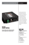
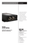
MODEL 6010A UNIVERSAL SWITCHING POWER SUPPLY (For Use With Model 6000A Card Cage) USER’S MANUAL WORLD HEADQUARTERS 55 Cabot Court Hauppauge, NY 11788 USA TEL: (631) 273-0404 FAX:(631) 273-1638 WWW: http://www.commspecial.com EMAIL: [email protected] Communications Specialties Pte Ltd 180B Bencoolen Street #05-01 The Bencoolen Singapore 189648 TEL: +65 6837 8790 FAX: +65 6333 0501 EMAIL: [email protected] P/N: 120157 REV D 8 1 WARRANTY INTRODUCTION Communications Specialties Inc. warrants that for a period of three years after purchase by the Buyer, all fiber optic transmission systems will be free from defects in material and workmanship under normal use and service. A Return Material Authorization (RMA) number must be obtained from the company before any equipment is returned by the Buyer. All material must be shipped to Communications Specialties Inc. at the expense and risk of the Buyer. The Model 6010A universal switching power supply plugs directly into the Model 6000A rack-mountable card cage and is designed to provide power to most combinations of rack-mountable Pure Digital One Fiber™ , Fiberlink or Pure Digital Fiberlink modules (or cards). This supply occupies three adjacent positions in the card cage. For redundant operation, more than one Model 6010A power supply may be used. Communications Specialties Inc. obligation under this warranty will be limited, at its option, to either the repair or replacement of defective units, including free materials and labor. In no event shall the company be responsible for any incidental or consequential damages or loss of profits or goodwill. Communications Specialties Inc. shall not be obligated to replace or repair equipment that has been damaged by fire, war, acts of God, or similar causes, or equipment that has been serviced by unauthorized personnel, altered, improperly installed or abused. RMA numbers and repairs can be obtained from: Communications Specialties, Inc. 55 Cabot Court Hauppauge, NY 11788 USA TEL: (631) 273-0404 FAX: (631) 273-1638 or, in the Asia Pacific Region: Communications Specialties Pte Ltd TEL: +65 6837 8790 FAX: +65 6333 0501 (See cover of this manual for complete address) RMA numbers can also be obtained from our web site: http://www.commspecial.com Please have your serial number (located underneathyour unit) available when contacting us. 6 The Model 6010A universal switching power supply is certified to meet the safety and EMI requirements of most regulatory agencies in the US, Canada and abroad. TECHNICAL SPECIFICATIONS Number of Positions Occupied 3 Input Voltage Range (Continuous) 90 to 260 VAC 47/63 Hz Output Voltage +8.5 VDC + 1% Regulated Output Current 0 to +50 C, 10A Continuous -35 to +75 C, 6.5A Continuous Over-voltage Protection Crowbar at 9.5 to 11.5V Short Circuit Protection Current Limiting Input Protection P/C fuse for catastrophic failure Ripple and Noise 1% pp maximum, DC to 15 MHz Switching Frequency Greater than 30 KHz Efficiency 75% minimum EMI Compliance EMI Compliance FCC 20870 Curve B, VDE EN55022 Class B, European CE Safety Compliance UL1950, CSA22.2 No.220, VDE EN60950, European CE Shock MIL-STD 810E Method 516.4 Vibration MIL-STD 810E Method 514.4 Input Power Connector IEC Universal Type 3 INSTALLATION AND OPERATION OF MODEL 6010A 1. Plug the Universal Switching Power Supply into the Model 6000A card cage. The unit will occupy three, adjacent positions. (You may choose which three.) If redundant operation is desired, additional Model 6010A units may also be inserted, with each occupying an addition three positions. 2. Plug a suitable line cord into the rear IEC power connector. Note that the Model 6010A will automatically operate from all AC power sources between 90 and 260 volts at 50 or 60 Hz. No user adjustments are required. 3. Use the front panel power switch to turn the unit on. An illuminated power indicator LED signifies the presence of power. The Model 6010A universal switching power supply is “hot swappable,” meaning that it may be inserted or removed from the card cage without first turning off the power. This feature is important when using redundant power supplies, as it gives the user freedom to remove or add a second power supply while maintaining operation of all transmission modules in the cage. FCC STATEMENT WARNING: This equipment generates, uses and can radiate radio frequency energy and if not installed and used in accordance with the instruction manual, may cause interference to radio communications. It has been tested and found to comply with the limits for a Class A computing device pursuant to Subpart B of Part 15 of FCC Rules, which are designed to provide reasonable protection against such interference when operated in a commercial environment. Operation of this equipment in a residential area is likely to cause interference in which case the user, at his own expense, will be required to take whatever measures may be required to correct the interference. WARNING: TO REDUCE THE RISK OF FIRE OR ELECTRONIC SHOCK, DO NOT EXPOSE THIS APPLIANCE TO RAIN OR MOISTURE. CAUTION Do not use the Model 6010A universal switching power supply and an external userprovided power source simultaneously. Doing so may result in damage to either the supply or to the transmission card/modules in the card cage. RISK OF ELECTRIC SHOCK DO NOT OPEN CAUTION: BUILT-IN ALARM FEATURE FOR REDUNDANT OPERATION The Model 6010A contains an output voltage-sensing circuit that operates when two or more power supplies and a model 6020A Alarm Sensing Module are employed in the same card cage. If one supply should fail, a signal is produced that will activate the Alarm Sensing Module. This results in a blinking LED, a piezo sounder and activation of a set of external contacts (on the Alarm Sensing Module) that can be used to remotely signify the occurrence of the failure. This feature is not available when only one power supply is employed. 4 TO REDUCE THE RISK OF ELECTRONIC SHOCK, DO NOT REMOVE COVER. NO USER SERVICEABLE PARTS INSIDE. REFER SERVICING TO QUALIFIED SERVICE PERSONNEL. This symbol warns the user of uninsulated voltage within the unit that can cause dangerous electronic shocks. This symbol alerts the user that there are important operating and maintenance instructions in the literature accompanying this unit. 5 INSTALLATION AND OPERATION OF MODEL 6010 1. Plug the Universal Switching Power Supply into the Model 6000 card cage. The unit will occupy three, adjacent positions. (You may choose which three.) If redundant operation is desired, additional Model 6010 units may also be inserted, with each occupying an addition three positions. 2. Plug a suitable line cord into the rear IEC power connector. Note that the Model 6010 will automatically operate from all AC power sources between 90 and 260 volts at 50 or 60 Hz. No user adjustments are required. 3. Use the front panel power switch to turn the unit on. An illuminated power indicator LED signifies the presence of power. The Model 6010 universal switching power supply is “hot swappable,” meaning that it may be inserted or removed from the card cage without first turning off the power. This feature is important when using redundant power supplies, as it gives the user freedom to remove or add a second power supply while maintaining operation of all transmission modules in the cage. FCC STATEMENT WARNING: This equipment generates, uses and can radiate radio frequency energy and if not installed and used in accordance with the instruction manual, may cause interference to radio communications. It has been tested and found to comply with the limits for a Class A computing device pursuant to Subpart B of Part 15 of FCC Rules, which are designed to provide reasonable protection against such interference when operated in a commercial environment. Operation of this equipment in a residential area is likely to cause interference in which case the user, at his own expense, will be required to take whatever measures may be required to correct the interference. WARNING: TO REDUCE THE RISK OF FIRE OR ELECTRONIC SHOCK, DO NOT EXPOSE THIS APPLIANCE TO RAIN OR MOISTURE. CAUTION Do not use the Model 6010 universal switching power supply and an external userprovided power source simultaneously. Doing so may result in damage to either the supply or to the transmission card/modules in the card cage. RISK OF ELECTRIC SHOCK DO NOT OPEN CAUTION: BUILT-IN ALARM FEATURE FOR REDUNDANT OPERATION The Model 6010 contains an output voltage-sensing circuit that operates when two or more power supplies and a model 6020 Alarm Sensing Module are employed in the same card cage. If one supply should fail, a signal is produced that will activate the Alarm Sensing Module. This results in a blinking LED, a piezo sounder and activation of a set of external contacts (on the Alarm Sensing Module) that can be used to remotely signify the occurrence of the failure. This feature is not available when only one power supply is employed. 4 TO REDUCE THE RISK OF ELECTRONIC SHOCK, DO NOT REMOVE COVER. NO USER SERVICEABLE PARTS INSIDE. REFER SERVICING TO QUALIFIED SERVICE PERSONNEL. This symbol warns the user of uninsulated voltage within the unit that can cause dangerous electronic shocks. This symbol alerts the user that there are important operating and maintenance instructions in the literature accompanying this unit. 5 WARRANTY INTRODUCTION Communications Specialties Inc. warrants that for a period of three years after purchase by the Buyer, all fiber optic transmission systems will be free from defects in material and workmanship under normal use and service. A Return Material Authorization (RMA) number must be obtained from the company before any equipment is returned by the Buyer. All material must be shipped to Communications Specialties Inc. at the expense and risk of the Buyer. The Model 6010 universal switching power supply plugs directly into the Model 6000 rack-mountable card cage and is designed to provide power to most combinations of rack-mountable Pure Digital One Fiber™ , Fiberlink or Pure Digital Fiberlink modules (or cards). This supply occupies three adjacent positions in the card cage. For redundant operation, more than one Model 6010 power supply may be used. Communications Specialties Inc. obligation under this warranty will be limited, at its option, to either the repair or replacement of defective units, including free materials and labor. In no event shall the company be responsible for any incidental or consequential damages or loss of profits or goodwill. Communications Specialties Inc. shall not be obligated to replace or repair equipment that has been damaged by fire, war, acts of God, or similar causes, or equipment that has been serviced by unauthorized personnel, altered, improperly installed or abused. RMA numbers and repairs can be obtained from: Communications Specialties, Inc. 55 Cabot Court Hauppauge, NY 11788 USA TEL: (631) 273-0404 FAX: (631) 273-1638 or, in the Asia Pacific Region: Communications Specialties Pte Ltd TEL: +65 6837 8790 FAX: +65 6333 0501 (See cover of this manual for complete address) RMA numbers can also be obtained from our web site: http://www.commspecial.com Please have your serial number (located underneathyour unit) available when contacting us. 6 The Model 6010 universal switching power supply is certified to meet the safety and EMI requirements of most regulatory agencies in the US, Canada and abroad. TECHNICAL SPECIFICATIONS Number of Positions Occupied 3 Input Voltage Range (Continuous) 90 to 260 VAC 47/63 Hz Output Voltage +8.5 VDC + 1% Regulated Output Current 0 to +50 C, 10A Continuous -35 to +75 C, 6.5A Continuous Over-voltage Protection Crowbar at 9.5 to 11.5V Short Circuit Protection Current Limiting Input Protection P/C fuse for catastrophic failure Ripple and Noise 1% pp maximum, DC to 15 MHz Switching Frequency Greater than 30 KHz Efficiency 75% minimum EMI Compliance EMI Compliance FCC 20870 Curve B, VDE EN55022 Class B, European CE Safety Compliance UL1950, CSA22.2 No.220, VDE EN60950, European CE Shock MIL-STD 810E Method 516.4 Vibration MIL-STD 810E Method 514.4 Input Power Connector IEC Universal Type 3