1
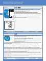
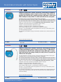
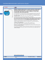
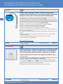
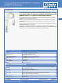
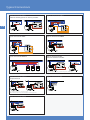
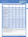
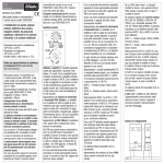
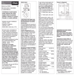
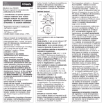
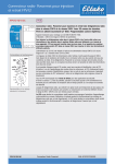
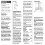
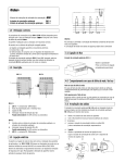
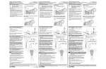
Eltako – Der Gebäudefunk
Die Basis mit Sensoren und Aktoren
1
4
Eltako Powerline – The ideal supplement to the
Eltako Wireless Building System with EnOcean
4
Eltako Powerline
Wireless Powerline gateway FPLG14 and Powerline pushbutton gateway PL-FTGW
Decentralised actuator PL-SAM1L with sensor input and
decentralised actuator PL-SAM2L with sensor inputs
Decentralised Venetian blind actuator PL-SAM2 with sensor inputs
Decentralised universal dimmer actuator with sensor input PL-SAMDU
Decentralised dimmer actuator PL-SAMDR with sensor input and
decentralised dimmer actuator PL-AMD10V
Decentralised TLZ actuator PL-SAM1LT with sensor input and decentralised sensor input PL-SM1L
Decentralised 8-channel sensor input PL-SM8 and
Temperature controller PL-SAMTEMP for heating and cooling
Coupling element PL-SW-PROF for Software SIENNA®-Professional
Typical connections
Technical data Powerline devices
The electricity wiring in buildings acts as the Eltako
Powerline bus. Now you can transmit sensor data
and telegrams to actuators over the existing electricity
wiring instead of broadcasting wireless telegrams
– that is the basic difference between the two
technologies.
4-1
4-2
4-3
4-4
4-5
4-6
4-7
4-8
4-9
4 - 10
4 - 11
Wireless Powerline Gateway and
Powerline Pushbutton Gateway
FPLG14
Wireless Powerline gateway. Bidirectional. Standby loss only 0.4 watt.
Modular device for DIN-EN 60715 TH35 rail mounting.
2 module = 36 mm wide, 58 mm deep.
This gateway translates wireless and Powerline telegrams in both directions.
All Powerline telegrams from the electricity wiring system are automatically translated into
RS485 bus telegrams and may also be sent as wireless telegrams by connected FTD14 devices.
Only wireless and RS485 bus telegrams taught into the FPLG14 are translated into Powerline
telegrams and modulated onto the electricity wiring system. Up to 120 different addresses.
Teach-in takes place by means of rotary switches on the front of the devices or using the
PCT14 as described in the user's manual.
4-2
Function rotary switches
Standard setting ex works.
FPLG14
Wireless Powerline gateway
EAN 4010312316771
91,60 € /pc.
PL-SAM1L
PL-FTGW
Bidirectional Powerline pushbutton gateway. 53x43 mm, 40 mm deep for
mounting in 58 mm switch boxes.
Supply voltage 230 V. Power consumption in operation 1.1 Watt.
Powerline telegrams from the grid taught-in into the gateway are automatically transformed
and sent into Eltako-wireless telegrams.
Wireless telegrams taught-in into the gateway are transformed into powerline telegrams and
modulated to the power supply grid.
By pressing the reset button, the PL-FTGW will be put into the teaching-in mode. The rotary switch selects , whether wireless or powerline
telegrams should be taught-in.
One being taught powerline sensor is automatically assigned by operating in the learning mode , a free radio channel .
A free wireless channel is automatically assigned to a taught-in powerline sensor with confirmation in teaching-in mode.
Up to 80 Powerline sensors or feedbacks can be taught-in. The function as a universal, direction or central pushbutton for a
taught-in wireless sensor is assigned via slide switch of the PL-FTGW. The Powerline address is set via rotary switch g and e which
should be addressed with the wireless sensor. In addition to wireless switches also Eltako wireless sensors such as window
contacts and motion detectors can be taught-in. Also control functions of the GFVS for dimmer switches and roller shutter control is
possible. The implementation into practical Powerline telegrams für PL actuators is done automatically. Up to 100 different wireless
sensor can be taught-in.
All records and configurations can be accessed via Sienna-Professional software and power supply. Other functions can then be
selected which are not available through the direct teaching-in via rotary switch.
In addition, the gateway can be set into the learn and deletion mode, so that a manual teaching-in can be carried out without
direct access to the device.
The PL-FTGW also serves as a relay station for communication between the temperature controller PL-SAMTEMP with EnOcean
actuators FKS-MD1 and FKS-E. Up to 20 actuators and PL-SAMTEMP are managed here.
Available november 2015.
PL-FTGW
Powerline-Aktor 1 Kanal mit
EAN 4010312316665
Lagertype
107,40 €/St.
Sensoreingang
230 V gateway
Powerline
pushbutton
EAN 4010312316986
166,40 € /pc.
Recommended retail prices excluding VAT.
Decentralised Actuator with Sensor Inputs
PL-SAM1L
Powerline actuator with 1 channel. 53x43 mm, 25 mm deep, for mounting
in 58 mm switch boxes. Used as impulse switch or relay. 1 NO contact not
potential free 10 A/250 V AC, incandescent lamps 2000 watts. Sensor input
230V. Standby loss only 0,5 watt. To control and switch at the same place.
Two rotary switches are located on the front for address assignment:
The left rotary switch defines the group address g with 16 alphabetical values from A to P.
The right rotary switch defines the element address e with 16 numerical values from 0 to 15.
Above it is a slide switch which acts as a configuration switch with positions 0, 1 and 2.
Position 0: Sensor input functions as pushbutton (impulse switch).
Position 1: Sensor input functions as NO contact (relay).
Position 2: A change-over switch is evaluated as a pushbutton.
To the left of the rotary switches is a red LED which indicates all activities.
Next to it is a reset pushbutton and to the right of that is a service pin. For functions, please
refer to the operating instructions.
The terminals located above are plug-in terminals for conductor cross-sections of 0.2mm² to
1.5mm².
Typical connections on page 4-10.
PL-SAM1L
Powerline actuator 1 channel with
sensor
EAN
4010312316665
107,40 €/St.
EAN 4010312316665
input 230 V
103,70 € /pc.
PL-SAM2L
Powerline actuator with 2 channels. 53x43 mm, 25 mm deep for mounting
in 58 mm switch boxes. Used as impulse switch or relay. 1+1 NO contacts
not potential free 5A/250V AC, incandescent lamps 1000 watts. 2 sensor
inputs with internal low voltage. Standby loss only 0,5 watt. To control and
switch at the same place.
Use only potential free switching elements. Internal low voltage applied to the sensor inputs.
Two rotary switches are located on the front for address assignment:
The left rotary switch defines the group address g with 16 alphabetical values from A to P.
The right rotary switch defines the element address e with 16 numerical values from 0 to 15.
Above it is a slide switch which acts as a configuration switch with positions 0, 1 and 2.
Position 0: Sensor inputs function as pushbuttons (impulse switches).
Position 1: Sensor input functions as NC contact (relay).
Position 2: A change-over switch is evaluated as a pushbutton.
To the left of the rotary switches is a red LED which indicates all activities.
Next to it is a reset pushbutton and to the right of that is a service pin. For functions, please
refer to the operating instructions.
The terminals located above are plug-in terminals for conductor cross-sections of 0.2mm² to
1.5mm². Next to them are three wires with wire end-sleeves for the two control inputs with
internal low voltage.
Typical connections on page 4-10.
PL-SAM2L
Powerline actuator 2 channels with
2 sensor inputs
Recommended retail prices excluding VAT.
EAN 4010312316672
105,40 € /pc.
4-3
Venetian Blind Actuator with Sensor Inputs
PL-SAM2
Powerline Venetian blind actuator for 1 motor. 53x43 mm, 25 mm deep for
mounting in 58mm switch boxes. 1+1 NO contact for motors up to 3A.
2 sensor inputs with internal low voltage. Standby loss only 0,5 watt.
To control and switch at the same place.
4-4
Use only potential free switching elements. Internal low voltage applied to the sensor inputs.
The control inputs can be used for a Venetian blind pushbutton or a Venetian blind switch.
The runtime is preset to 120 seconds. This can be changed using the SIENNA-Professional
installation software.
Two rotary switches are located on the front for address assignment:
The left rotary switch defines the group address g with 16 alphabetical values from A to P.
The right rotary switch defines the element address e with 16 numerical values from 0 to 15.
Above it is a slide switch which acts as a configuration switch with positions 0, 1 and 2.
Position 0: Start and stop by pressing Venetian blind pushbutton. Auto stop at end.
Position 1: Comfort switch for Venetian blind slat adjustment. Tip briefly to adjust slats.
>1 second same as position 0.
Position 2: Tip pushbutton to operate, release to stop. Auto stop at end.
To the left of the rotary switches is a red LED which indicates all activities.
Next to it is a reset pushbutton and to the right of that is a service pin. For functions, please
refer to the operating instructions.
The terminals located above are plug-in terminals for conductor cross-sections of 0.2mm² to
1.5mm². Next to them are three wires with wire end-sleeves for the two control inputs with
internal low voltage.
Typical connections on page 4-10.
PL-SAM2
Powerline Venetian blind actuator for
1 motor
Recommended retail prices excluding VAT.
EAN 4010312316689
105,40 € /pc.
Decentralised Universal Dimmer Actuator
with Sensor Input
PL-SAMDU
Powerline universal dimmer actuator. 53x43mm, 40mm deep for mounting
in 58 mm switch boxes. Power MOSFET up to 300 W. Automatic lamp
detection. Sensor input 230V. Standby loss only 0,6 Watt. To control and
dim at different places.
Universal dimmer switch for lamps up to 300 W, dependent on ventilation conditions.
Dimmable energy saving lamps ESL and dimmable 230V-LED lamps, additionally dependent
on the lamps electronics. No minimum load.
Zero passage switching with soft ON and soft OFF to protect lamps.
Short-time control commands switch on/off, permanent control varies the brightness to the
maximum level.
A interruption of control changes the direction of dimming.
The brightness level is stored on switch-off (memory).
In case of a power failure the switch position and the brightness stage are stored and may be
switched on when the power supply is restored.
Automatic electronic overload protection and overtemperature switch-off.
Two rotary switches are located on the front for address assignment:
The left rotary switch defines the group address g with 16 alphabetical values from A to P.
The right rotary switch defines the element address e with 16 numerical values from 0 to
15.
Above it is a slide switch which acts as a configuration switch:
The position AUTO1 allows the dimming of all types of lamps up to 300 watts.
The position LC1 is a comfort position for LED lamps up to 150 watts which are not being
dimmed down enough when set to AUTO (trailing phase angle) dependent on the construction
and must therefore be forced to leading phase angle.
The position AUTO2 allows the dimming of all types of lamps up to 300 watts.
Increased minimum brightness compared to AUTO1.
In position LC1 no inductive (wound) transformers should be used. In addition, the maximum
number of dimmable LED lamps can be lower than in the AUTO position dependent on the
construction.
Mixing of L loads (inductive loads, e.g. wound transformers) and C loads (capacitive loads,
e.g. electronic transformers) is not permitted. R loads (ohmic loads, e.g. 230V incandescent
lamps and halogen lamps) may be added anytime.
To the left of the rotary switches is a red LED which indicates all activities.
Next to it is a reset pushbutton and to the right of that is a service pin. For functions, please
refer to the operating instructions.
The terminals located above are plug-in terminals for conductor cross-sections of 0.2mm2 to
1.5mm².
Typical connections on page 4-10.
PL-SAMDU
Powerline universal dimmer actuator
1 channel with sensor input 230V
Recommended retail prices excluding VAT.
EAN 4010312316870
119,60 €/pc.
4-5
Decentralised Dimmer Actuator with Sensor Input and
Decentralised Dimmer Actuator 1-10 Volt
PL-SAMDR
Powerline dimmer actuator with 1 channel. 53x43mm, 25mm deep for
mounting in 58mm switch boxes. Phase control dimmer for loads up to
300 W at cos phi = 1 and 150 W at cos phi = 0.6. Electronic universal
transformers up to 150W. Sensor input 230V. Standby loss only 0,5 watt.
To control and dim at the same place.
4-6
Overload cut-off with auto recovery after 60 seconds.
Two rotary switches are located on the front for address assignment:
The left rotary switch defines the group address g with 16 alphabetical values from A to P.
The right rotary switch defines the element address e with 16 numerical values from 0 to 15.
Above it is a slide switch which acts as a configuration switch with positions 0, 1 and 2.
Position 0: Dimmer switch for R and L loads up to 300W at cos phi = 1 and 150W at cos phi
= 0.6. Dimming range 10-100%.
Position 1: Dimmable LED lamps with phase control. Dimming range 15-100%.
Position 2: Dimmer switch for electronic universal transformers up to 150W. Important:
Please observe the minimum load of universal transformers. Dimming range from 30 to
100%. Also suitable to control fountain pumps. Dimming range 35-100%.
To the left of the rotary switches is a red LED which indicates all activities.
Next to it is a reset pushbutton and to the right of that is a service pin. For functions, please
refer to the operating instructions.
The terminals located above are plug-in terminals for conductor cross-sections of 0.2mm² to
1.5mm².
Typical connections on page 4-10.
PL-SAMDR
Powerline dimmer actuator 1 channel
with sensor input 230V
EAN 4010312316696
105,40 € /pc.
PL-AMD10V
Powerline dimmer actuator 1-10 V. 53x43 mm, 25 mm deep, for mounting in
58 mm switch boxes. To switch and/or dim via a 1-10 V interface. 1 NO nonfloating contact 600VA. Standby loss only 0,5 watt. To activate and dim at
different places.
Current sink of max. 30mA for active and passive electronic ballasts.
A Powerline sensor input is required for activation.
Two rotary switches are located on the front for address assignment:
The left rotary switch defines the group address g with 16 alphabetical values from A to P.
The right rotary switch defines the element address e with 16 numerical values from 0 to 15.
Above it is a slide switch which has no function here.
To the left of the rotary switches is a red LED which indicates all activities. Next to it is a reset
pushbutton and to the right of that is a service pin. For functions, please refer to the operating
instructions.
The terminals located above are plug-in terminals for conductor cross-sections of 0.2mm² to
1.5mm².
Typical connections on page 4-10.
PL-AMD10V
Powerline dimmer actuator 1-10V
Recommended retail prices excluding VAT.
EAN 4010312316726
105,40 € /pc.
Decentralised TLZ Actuator with Sensor Input
and Decentralised Sensor Input 230V
PL-SAM1LT
Powerline TLZ (staircase time switch) actuator with 1 channel. 53x43mm,
25mm deep for mounting in 58mm switch boxes. Off delay settable from
1 minute to 120 minutes. 1 NO contact not potential free 10A/250V AC,
incandescent lamps 2000 watts. Sensor input 230 V. Standby loss only
0,5 watt. To control and switch at the same place.
Two rotary switches are located on the front for address assignment:
The left rotary switch defines the group address g with 16 alphabetical values from A to P.
The right rotary switch determines the off-delay time.
Above it is a slide switch which acts as a configuration switch with positions 0, 1 and 2.
Position 0: Pushbutton at sensor input with subsequent switching.
Position 1: Same as Position 0 but with switch-off early warning.
Position 2: A change-over switch is evaluated as a pushbutton.
To the left of the rotary switches is a red LED which indicates all activities.
Next to it is a reset pushbutton and to the right of that is a service pin. For functions, please
refer to the operating instructions.
The terminals located above are plug-in terminals for conductor cross-sections of
0.2mm² to 1.5mm².
Typical connections on page 4-10.
PL-SAM1LT
Powerline TLZ actuator 1 channel with
sensor input 230 V
EAN 4010312316702
105,40 € /pc.
PL-SM1L
Powerline sensor input with 1 channel. 53x43mm, 25mm deep for mounting
in 58mm switch boxes. Sensor input 230V. Standby loss only 0,5 watt.
To control and switch at different places.
When pressed, the sensor input acts on all actuators with the same address or as a central
pushbutton if element address 0 is used.
Two rotary switches are located on the front for address assignment:
The left rotary switch defines the group address g with 16 alphabetical values from A to P.
The right rotary switch defines the element address e with 16 numerical values from 0 to 15.
Above it is a slide switch which acts as a configuration switch with positions 0, 1 and 2.
Position 0: Sensor input with reset function as pushbutton.
Position 1: Sensor input functions as NO contact.
Position 2: A change-over switch is evaluated as a pushbutton.
To the left of the rotary switches is a red LED which indicates all activities.
Next to it is a reset pushbutton and to the right of that is a service pin. For functions, please
refer to the operating instructions.
The terminals located above are plug-in terminals for conductor cross-sections of 0.2mm² to
1.5mm².
Typical connections on page 4-10.
PL-SM1L
Powerline sensor input 230V
Recommended retail prices excluding VAT.
EAN 4010312316740
99,90 € /pc.
4-7
Decentralised 8-channel Sensor Input and
Temperature controller for heating and cooling
PL-SM8
Powerline sensor input with 8 channels. 53x43mm, 25mm deep for
mounting in 58mm switch boxes. 8 sensor inputs with internal low voltage.
Standby loss only 0,5 watt. To control and switch at different places.
Use only potential free switching elements. Internal low voltage applied to the sensor inputs.
Two rotary switches are located on the front for address assignment:
The left rotary switch defines the group address g with 16 alphabetical values from A to P.
The right rotary switch defines the element address e with 16 numerical values from 0 to 15.
Above them is a slide switch which functions as a configuration switch.
Position 0: 2 adjacent inputs as direction pushbuttons for UP/DOWN or ON/OFF.
Position 1: All sensor inputs function separately as NO contacts.
Position 2: All sensor inputs function separately as pushbuttons.
To the left of the rotary switches is a red LED which indicates all activities.
Next to it is a reset pushbutton and to the right of that is a service pin. For functions, please
refer to the operating instructions.
The terminals located above are plug-in terminals for conductor cross-sections of 0.2mm² to
1.5mm².
The addresses of the 8 inputs can also be freely assigned if necessary using the SIENNAProfessional software.
The socket strip located above this has 9 plug-in wires with wire end-sleeves.
8 control inputs with internal low voltage.
4-8
Typical connections on page 4-10.
PL-SM8
Powerline sensor inputs, 8 channels,
internal low voltage
EAN 4010312316719
105,40 € /pc.
PL-SAMTEMP
Powerline temperature controller with display, white, 50x50mm, for mounting in switch systems. In addition a floating control contact 3A/250V AC
for direct connection of heaters and coolers. Standby loss only 0,5 watt.
The scope of supply comprises a frame R1E and an intermediate frame ZR65/55 for the
E-Design, the temperature controller upper part and a bottom part for attachment in 58 mm
flush-mounted boxes.
In normal mode the current room temperature is indicated in the display as well as icons
for 'present' or 'absent' and for 'heating on' or 'cooling active'.
Press the pushbuttons
(absent) and
(present) to activate the associated setpoint.
In setup mode as described in the user's manual, press pushbuttons ▲ and ▼ to display the
setpoint and actual temperatures and change the setpoints.
Control heating or cooling with Powerline actuators PL-SAM1L or PL-SAM2L.
PL-SAMTEMP
Powerline Temperature controller for
heating and cooling
Recommended retail prices excluding VAT.
EAN 4010312316733
198,90 € /pc.
Coupling Element PL-SW-PROF for Software
SIENNA®-Professional
PL-SW-PROF
The coupling element with USB cable and 230V power supply unit is included
in the scope of supply. The software for installation and configuration of the
powerline devices PL is available for download under eltako.com.
PL-SW-PROF is a Windows-based program for installing and configuring all PL and SIENNA
components and is designed for electricians.
Powerline systems can either be installed or configured using a screwdriver or a PC/laptop.
All changes can be made from the PC. Existing installations in a building can also be read
and detected.
The bus is coupled using a USB port on the PC. Thanks to Powerline technology, the nearest
electric socket becomes a bus coupler.
Download in accordance with the included installation instructions from the homepage
eltako.com/en -> Software -> Powerline. The operating instructions are available for download
at the bottom of the page under Operating Instructions/SIENNA Professional.
System requirements, Laptop / PC
Processor
Intel® Pentium® III 366MHz or higher
Operating system
Server 2003, Windows XP, Vista,
Windows 7, Windows 8 (32 Bit and 64 Bit)
Programming environment
Hard disc memory
RAM memory
Screen resolution
Interface
Microsoft .NET Framework 3.5 SP1 or higher
32 MB free space on hard disc
128 MB RAM
1024 x 768
USB 1.1, 2.0 or 3.0
Technical data Echelon-Koppelelement PL-20
Technology
Powerline communication on B/C tape (5Kb/s); acc. to FCC, CENELEC EN50065-1
and LONWORKS® protocol
Bus coupler
PC coupler
Fused safety socket, 230 V~/50 Hz
USB 1.1 or 2.0
Current draw
Mains plug/power supply unit: maximum 250mA at 18V DC voltage.
USB: maximum 50mA at 5V DC voltage
Processor type
Temperature range
Neuron processor integrated in Powerline Smart Transceiver PL 3120
-25ºC to +70ºC
PL-SW-PROF
Software PL-SW-PROF
Recommended retail prices excluding VAT.
EAN 4010312316856
333,40 € /pc.*
* The software part is not discountable.
4-9
Typical Connections
Typical connection PL-SAM1L
Additional switching point for an existing consumer
Typical connection PL-SAM2L
Typical connection PL-SAM2
Typical connection PL-SAMDR
Typical connection PL-AMD10V
Typical connection PL-SM1
Switch an additional consumer
4-10
(e.g. mirror light in bathroom, socket in living room, outside light)
Typical connection PL-SAM1LT
Delayed switch-off
(e.g. staircase time switch or circulation pump)
SAM1LT switches itself and associated actuators off after a preset time.
Typical connection PL-SAMDU
Typical connection PL-SM8
Technical Data
Powerline Devices
PL-SAMDR
PL-SAMDU
PL-AMD10V
PL-SAM1L
PL-SAM1LT
PL-SAM2L
PL-SAM2
Contacts
Contact material/contact gap
Triac
SAMDU: Power MOSFET
AgSnO / 0.5 mm
AgSnO / 0.5 mm
AgSnO / 0.5 mm
AgSnO / 0.5 mm
Spacing of control connections/contact
–
–
3 mm
3 mm
3 mm
Test voltage control connections/contact
–
–
2000 V
2000 V
2000 V
Rated switching capacity each contact
–
600 VA
10 A / 250 V AC
5 A/ 250 V AC
3 A/250 V AC
up to 300 W 2)
–
2000 W
1000 W
–
Inductive laod cos M= 0.6/230 V AC
inrush current d35 A
up to 150 W
SAMDU: up to 300 W 6)
–
650 W
650 W 5)
650 W 5)
Fluorescent lamp load with KVG *
in lead-lag circuit or non compensated
–
–
1000 VA
500 VA
–
Fluorescent lamp load with KVG *
shunt-compensated or with EVG*
–
600 VA 4)
500 VA
250 VA
–
Compact fluorescent lamps with EVG*
and energy saving lamps
–
–
bis 400 W
–
–
Dimmable 230V LED lamps
up to 150 W 3)
SAMDU: up to 300 W 3)
–
bis 400 W
–
–
Service life at rated load, cos M = 1
or incandescent lamps 500W at 100/h
–
> 10
> 10
> 10
Service life at rated load,
cos M= 0.6 at 100/h
–
> 4 x 10
Max. operating cyles
–
10 /h
Connection type
Plug-in terminals
Plug-in terminals
Plug-in terminals
Plug-in terminals
Plug-in terminals
Minimum conductor cross-section
0.2mm
2
0.2 mm
2
0.2 mm
2
0.2 mm
2
0.2 mm
Maximum conductor cross-section
1.5 mm
2
1.5 mm
2
1.5 mm
2
1.5 mm
2
1.5 mm
Conductor stripping
8-9mm
8-9 mm
8-9 mm
8-9 mm
8-9 mm
Type of enclosure/terminals
IP30 / IP20
IP30 / IP20
IP30 / IP20
IP30 / IP20
IP30 / IP20
100%
100%
100%
100%
100%
+50°C/-20°C
+50°C/-20°C
+50°C/-20°C
+50°C/-20°C
0.5 W
0.5 W
0.5 W
0.5 W
Incandescent lamp and halogen lamp load
230V, I on d70 A /10 ms
2
4)
2
2
2
4-11
1)
5
4
5
> 4 x10
4
10 /h
3
> 10
5
> 4 x10
4
10 /h
3
5
> 4 x10
4
10 /h
3
3
2
2
Electronics
Time on
Max./min. temperature at mounting location +50°C /-20°C
Standby loss (active power)
0.5 W
SAMDU: 0.6W
Local control current at 230 V control input 0.4mA
Max. parallel capacitance (approx. length) 3 nF
of local control lead at 230 V AC
(10 m)
–
0.4 mA
0.4 mA
0.4 mA
–
3 nF
(10 m)
3 nF
(10 m)
3 nF
(10 m)
Applies to lamps of max. 150 W.
Also transformers electronically (C load), for SAMDR only up to 150 W.
3)
Generally applies to 230V LED lamps. Due to different lamp electronics, switch on/off problems and a restriction in the maximum number of lamps,
however, the dimming ranges may be limited depending on the manufacturer; in particular when the connected load is very low (e.g. with 5 W LEDs).
The comfort position LC1 at SAMDU optimizes the dimming range, which however results in a maximum capacity of only up to 150 W. In this comfort
position, no wound (inductive) transformers should be dimmed.
4)
Fluorescent lamps or LV halogen lamps with electronic ballast.
5)
All actuators with 2 contacts: Inductive load cos M = 0.6 as sum of both contacts 1000 W max.
6)
A maximum of 2 transformers of the same type.
* EVG = electronic ballast units; KVG = conventional ballast units
1)
2)
Powerline communication in the B/C-Band (5 kb/s) corresponds to FCC, CENELEC EN 50065-1 and LONWORKS protocol
Compliance with: EN 61000-6-3, EN 61000-6-1, EN 50065-1 and EN 60669