1
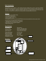
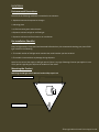
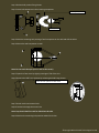
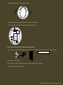
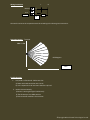
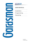
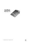
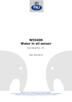
Technology and Trust…
USER MANUAL AND
INSTALLATION GUIDE
PART NAME:WPWM-88D
This document contains the complete user manual and
installation guide for the device WPWM-88D. It also contains the
connection diagrams that enable the user to employ our retrofit
technology without causing damage to the current wiring
situations leading to delay or disturbance in the current working
environment.
WHITE PLACARD TECHNOLOGIES PVT.LTD.
www.whiteplacard.com
Brief Introduction
WPWM-88D PIR Light Switch is a User friendly electronic gadget that can play a vital role in ENERGY
SAVING, eliminating manual control on application lighting. Its sleek and easy to adjust interface helps
the user to trim gadget to application suitable output. One can adjust ON-Time, LUX Trip level and
sensitivity at the tip of a screw driver for well groomed and dependable performance.
Features
1. Synchronous with AC230V, 50Hz.
2. Low power consumption.
3. Zero crossing (ZC) switching
4. Noise rejection circuit
5. Override function for ON (manual)/AUTO/Quick check (test)mode directly from power switch
6. Light sensor to Disable output during daytime
7. Adjustable ON time LUX trip level , Sensitivity
8. Auto-Reset incase ZC signal disappears
9. Wall /Ceiling mount
Specifications
1.PIR sensor
2.Power Supply
3.Maximum Load
4.Alarm period
5.Detectable Speed
6.Mounting Height
7.Detection Range
8.Adjustable Lux level
10.EMI/RFI Immunity
:
:
:
:
:
:
:
:
Dual element
230V AC+_10%,20mA Max
5A/250 VAC(1250VA Max)
75 seconds to 20 minute
0.5-15 m / Sec
2.1 m Typical
88.0 x 18m
1 Lux ~ Daylight
Fixing hole
Description
Wiring Terminals
Wire access holes
1
Relay
PIR Sensor
ON Time
Adjust
LDR
LUX Trip Level
Adjust
Sensitivity Adjust
Fixing hole
©Copyright White Placard Technologies Pvt.Ltd.
Installation
Environmental Precautions
Ensure that the following conditions are avoided in site selection:
1. Rapid environmental temperature changes
2. Vibrating place
3. In fluid corrosive gases and sea breeze
4. Exposure to direct sunlight or artificial light
5. Exposure to direct wind from heater or air conditioner
Pre Installation Checklist
Every PIR light switch is fully tested and examined before delivery. We recommend checking your piece of PIR
light switch for the following:
1. The model number of PIR light switch matches the model number you have ordered.
2. The model is intact without any damage during shipment.
Note: Do not connect the supply to PIR light switch if there is any sign of damage. Contact you supplier in case
of any queries regarding the shipment of condition of the model.
Mounting the Product
Mounting the PIR light switch without bracket: Skip steps 1 to 4
Wall / Ceiling Fixing Screw
Ball position Fixing Screw
©Copyright White Placard Technologies Pvt.Ltd.
Step 1: Release ball position fixing Screws
Step 2: Insert ball component in the mounting component
Mounting Component
Ball Component
Step 3: Mark the mounting hole positing of wall component on the wall and drill the holes.
Step 4: Mount the well component on wall.
Note: Do not touch the optic (Lens as well as the sensor).
Step 5: Open the front cover by slightly pressing on TOP of the Unit
Step 6: Remove the PCB from Unit base by releasing the PCB Fixing Screws.
Press here to open the front cover
Step 7: Knock out the wire access hole.
Step 8: Lead wire through the access hole.
Note: Step 9 and 10 will be used for PIR without bracket.
Step 9: Mark on the mounting hole position and drill the holes.
©Copyright White Placard Technologies Pvt.Ltd.
Step 10: Mount the Unit base firmly on the wall
Step 11: Complete the wiring as shown in wiring connection section
Step 12: Fix PCB to unit base with the Help of PCB Fixing screws.
Note: Step 13 will be used for PIR with Mounting Bracket.
Step 13: Fix Unit base of the PIR Light switch and Swivel arm of mounting bracket with the screws provided.
Bracket Mounting Position
Step 14: Fix the front cover
Step 15: Power on the unit adjust detection zone using the quick check mode
Step 16: Tighten the Position screws.
©Copyright White Placard Technologies Pvt.Ltd.
Quick Check Mode
The unit will enter in quick check mode if it is switched OFF-ON twice within 10 seconds after power ON. The
Load will remain on around 1.5 second after sensing motion across the sensor. Unit will enter in Auto mode
automatically if it does not sense any motion within 32 seconds.
Override Mode
The term override refers to the change of operating mode by switching the power switch OFF-ON twice within
three seconds after the warm up period
AUTO Mode
When working in AUTO mode ,the load will switch ON after detecting motion across the sensor and remain ON
for duration set by ‘NO’ time potentiometer.
ON Mode
The operating mode can be changed to ‘ON’ by switching the power switch OFF-ON twice within three
seconds. Load will remain ON continuously if the unit is working in ON mode and is not overridden to AUTO
mode it will return to AUTO mode automatically after 8 hours.
Note: Light sensor cannot be overridden by operating modes.
Adjustable Parameters
ON Time
When working in Auto mode the load will switch ON after detecting motion across the sensor. The ON time of
Load can be set from 23 seconds to 4 minutes by adjusting the ON Time Potentiometer from ‘MIN ‘to ‘MAX’
position the ON time of the Load will get extended until the sensor the motion across it.
Lux Trip Level
The LUX trip level can be adjusted from 2~2500 LUX by varying LUX Level potentiometer in Clockwise direction.
Sensitivity
Sensitivity of the light switch can be adjusted by varying Sensitivity POT if the sensitivity POT is rotated in clock
wise direction (i.e. Min to Max).the detection range covered will be minimum to maximum.
Note: It is recommended to keep the POT at factory calibrated setting.
©Copyright White Placard Technologies Pvt.Ltd.
Wiring Connection
L
Neutral
N
Live
L
N
L1
Load
LD
Connect the wires to the respective terminals according to the above given instructions.
Detection Pattern
Top view
1.8m - 3.7m
88.0 degrees
18 m
Troubleshooting
1.
Unit/Load is unfunctional : Make sure that
a) Power and Load connection are Correct.
b) Unit is exposed to LUX level more than the trip level
2. Load is ON continuously:
a) Sensor is sensing the signal continuously
b) The ON time pot is at MAX position
c) Environmental conditions are not meet.
©Copyright White Placard Technologies Pvt.Ltd.