1
CombiFlash® Rf User Manual For indoor use only COPYRIGHT © 2012 by Teledyne Isco 4700 Superior St. Lincoln, Nebraska, U.S.A. 68504 Phone: (402) 464-0231 Toll Free: (800) 228-4373 FAX: (402) 465-3022 Revision C, August 13, 2013 Part #60-5233-562 i CombiFlash® Rf User Manual ii CombiFlash® Rf User Manual Table of Contents 1. Introduction 1.1 Documentation Overview . . . . . . . . . . . . . . . . . . . . . . 1-1 1.2 Product Overview . . . . . . . . . . . . . . . . . . . . . . . . . . . . 1-1 1.3 Operating Overview . . . . . . . . . . . . . . . . . . . . . . . . . . 1-6 1.3.1 Multiple Control Possibilities . . . . . . . . . . . . . 1-6 1.3.2 File Storage . . . . . . . . . . . . . . . . . . . . . . . . . . . . 1-6 1.4 Specifications . . . . . . . . . . . . . . . . . . . . . . . . . . . . . . . 1-7 1.5 Controls, Indicators, and Features . . . . . . . . . . . . . 1-13 1.6 Safety . . . . . . . . . . . . . . . . . . . . . . . . . . . . . . . . . . . . 1-19 1.6.1 Hazard Severity Levels . . . . . . . . . . . . . . . . . 1-20 1.6.2 Hazard Symbols . . . . . . . . . . . . . . . . . . . . . . . 1-20 1.7 For Additional Information . . . . . . . . . . . . . . . . . . . 1-22 2. Preparation: Rf 200 and Rf 200i Systems 2.1 2.2 2.3 2.4 2.5 2.6 Unpacking the Unit . . . . . . . . . . . . . . . . . . . . . . . . . . 2-1 Instrument Location . . . . . . . . . . . . . . . . . . . . . . . . . 2-2 Connect Power . . . . . . . . . . . . . . . . . . . . . . . . . . . . . . 2-3 Connect Solvent Lines . . . . . . . . . . . . . . . . . . . . . . . . 2-3 Connect Waste Lines . . . . . . . . . . . . . . . . . . . . . . . . . 2-6 External Gas . . . . . . . . . . . . . . . . . . . . . . . . . . . . . . . . 2-8 2.6.1 CombiFlash Rf 200 and Rf 200i . . . . . . . . . . . . 2-8 2.6.2 CombiFlash Rf 200i Only . . . . . . . . . . . . . . . . . 2-9 2.7 Connect and Route Drain Lines . . . . . . . . . . . . . . . . 2-9 2.8 Position the System . . . . . . . . . . . . . . . . . . . . . . . . . 2-12 2.9 Install Collection Tube Racks . . . . . . . . . . . . . . . . . 2-12 2.10 External Detector (Optional) . . . . . . . . . . . . . . . . . . 2-14 2.11 Turn on Power . . . . . . . . . . . . . . . . . . . . . . . . . . . . . 2-15 2.12 Configure the System . . . . . . . . . . . . . . . . . . . . . . . . 2-15 2.12.1 Solvents . . . . . . . . . . . . . . . . . . . . . . . . . . . . . . 2-15 2.12.2 General Settings . . . . . . . . . . . . . . . . . . . . . . . 2-16 2.12.3 Set Date/Time . . . . . . . . . . . . . . . . . . . . . . . . . 2-16 2.12.4 Vapor Limit . . . . . . . . . . . . . . . . . . . . . . . . . . . 2-17 2.12.5 Set Default Tube Volumes . . . . . . . . . . . . . . . 2-17 2.12.6 User Preferences . . . . . . . . . . . . . . . . . . . . . . . 2-18 2.12.7 Restart the system . . . . . . . . . . . . . . . . . . . . . 2-20 2.13 Prime the Solvent Lines . . . . . . . . . . . . . . . . . . . . . . 2-21 iii CombiFlash® Rf User Manual 2.14 System Verification . . . . . . . . . . . . . . . . . . . . . . . . . 2-22 2.15 Installation Qualification Checklist . . . . . . . . . . . . 2-22 3. Preparation: Rf 150 Systems 3.1 Unpacking the Unit . . . . . . . . . . . . . . . . . . . . . . . . . 3-1 3.2 Instrument Location . . . . . . . . . . . . . . . . . . . . . . . . . 3-3 3.3 Connect Power . . . . . . . . . . . . . . . . . . . . . . . . . . . . . 3-3 3.4 Connect Solvent Lines . . . . . . . . . . . . . . . . . . . . . . . 3-4 3.5 Connect Waste Lines . . . . . . . . . . . . . . . . . . . . . . . . 3-6 3.6 Connect and Route Drain Lines . . . . . . . . . . . . . . . . 3-7 3.7 Position the System . . . . . . . . . . . . . . . . . . . . . . . . . 3-9 3.8 Install Collection Tube Racks . . . . . . . . . . . . . . . . 3-10 3.9 Turn on Power . . . . . . . . . . . . . . . . . . . . . . . . . . . . . 3-12 3.10 Configure the System . . . . . . . . . . . . . . . . . . . . . . . 3-12 3.10.1 Solvents . . . . . . . . . . . . . . . . . . . . . . . . . . . . . 3-13 3.10.2 General Settings . . . . . . . . . . . . . . . . . . . . . . 3-13 3.10.3 Set Date/Time . . . . . . . . . . . . . . . . . . . . . . . . 3-13 3.10.4 Vapor Limit (Optional) . . . . . . . . . . . . . . . . . 3-13 3.10.5 Set Default Tube Volumes . . . . . . . . . . . . . . 3-14 3.10.6 User Preferences . . . . . . . . . . . . . . . . . . . . . . 3-14 3.10.7 Restart the system . . . . . . . . . . . . . . . . . . . . 3-17 3.11 Prime the Solvent Lines . . . . . . . . . . . . . . . . . . . . . 3-18 3.12 System Verification . . . . . . . . . . . . . . . . . . . . . . . . . 3-19 3.13 Installation Qualification Checklist . . . . . . . . . . . . 3-20 4. Preparation: Optional 4x Module 4.1 4.2 4.3 4.4 4.5 4.6 4.7 4.8 4.9 4.10 4.11 4.12 Unpacking the Unit . . . . . . . . . . . . . . . . . . . . . . . . . 4-1 Instrument Location . . . . . . . . . . . . . . . . . . . . . . . . . 4-2 Connect Power . . . . . . . . . . . . . . . . . . . . . . . . . . . . . 4-2 Connect Solvent Lines . . . . . . . . . . . . . . . . . . . . . . . 4-3 Connect Waste Lines . . . . . . . . . . . . . . . . . . . . . . . . 4-4 Control Connection . . . . . . . . . . . . . . . . . . . . . . . . . 4-11 Position the System . . . . . . . . . . . . . . . . . . . . . . . . 4-11 Remove Shipping Hardware . . . . . . . . . . . . . . . . . 4-11 Turn on Power . . . . . . . . . . . . . . . . . . . . . . . . . . . . . 4-12 Prime the Solvent Lines . . . . . . . . . . . . . . . . . . . . . 4-13 System Verification . . . . . . . . . . . . . . . . . . . . . . . . . 4-14 Installation Qualification Checklist . . . . . . . . . . . . 4-15 5. Operation 5.1 Sample Preparation . . . . . . . . . . . . . . . . . . . . . . . . . 5.1.1 Liquid Sample Injection . . . . . . . . . . . . . . . . . 5.1.2 Solid Samples . . . . . . . . . . . . . . . . . . . . . . . . . 5.1.3 Preloading on Column . . . . . . . . . . . . . . . . . . iv 5-1 5-1 5-1 5-5 Table of Contents 5.2 Loading a RediSep Rf Column . . . . . . . . . . . . . . . . . . 5-5 5.3 Start a Default Method . . . . . . . . . . . . . . . . . . . . . . . 5-6 5.4 During the Run . . . . . . . . . . . . . . . . . . . . . . . . . . . . . . 5-9 5.4.1 Run Control Buttons . . . . . . . . . . . . . . . . . . . . 5-9 5.4.2 Bypassing the Solid Load Cartridge . . . . . . . 5-12 5.4.3 About Solvent Level Detection . . . . . . . . . . . . 5-14 6. User Help Reference 6.1 PeakTrak Overview. . . . . . . . . . . . . . . . . . . . . . . . . . . 6-1 6.1.1 PeakTrak Window Elements . . . . . . . . . . . . . . 6-1 6.1.2 Method File . . . . . . . . . . . . . . . . . . . . . . . . . . . . 6-2 6.1.3 Run File . . . . . . . . . . . . . . . . . . . . . . . . . . . . . . . 6-3 6.1.4 How to get PeakTrak help . . . . . . . . . . . . . . . . 6-3 6.2 PeakTrak Menu Options. . . . . . . . . . . . . . . . . . . . . . . 6-3 6.2.1 File . . . . . . . . . . . . . . . . . . . . . . . . . . . . . . . . . . . 6-3 6.2.2 Method Editor . . . . . . . . . . . . . . . . . . . . . . . . . . 6-7 6.2.3 Tools . . . . . . . . . . . . . . . . . . . . . . . . . . . . . . . . . . 6-7 6.2.4 Help . . . . . . . . . . . . . . . . . . . . . . . . . . . . . . . . . . 6-8 6.3 PeakTrak Windows . . . . . . . . . . . . . . . . . . . . . . . . . . . 6-9 6.3.1 Main Window. . . . . . . . . . . . . . . . . . . . . . . . . . 6-10 6.3.2 Method Editor . . . . . . . . . . . . . . . . . . . . . . . . . 6-14 6.3.3 Gradient Optimizer . . . . . . . . . . . . . . . . . . . . . 6-21 6.3.4 Column Data . . . . . . . . . . . . . . . . . . . . . . . . . . 6-22 6.3.5 Batch . . . . . . . . . . . . . . . . . . . . . . . . . . . . . . . . 6-22 6.3.6 Files . . . . . . . . . . . . . . . . . . . . . . . . . . . . . . . . . 6-23 6.3.7 Set Data Path . . . . . . . . . . . . . . . . . . . . . . . . . 6-25 6.3.8 Auto Prime/Valve Wash . . . . . . . . . . . . . . . . . 6-25 6.3.9 Manual Control . . . . . . . . . . . . . . . . . . . . . . . . 6-26 6.3.10 Configuration. . . . . . . . . . . . . . . . . . . . . . . . . . 6-27 6.3.11 Set Password . . . . . . . . . . . . . . . . . . . . . . . . . . 6-32 6.3.12 User Management . . . . . . . . . . . . . . . . . . . . . . 6-32 6.4 Examples of PeakTrak actions . . . . . . . . . . . . . . . . . 6-33 6.4.1 Starting a run using default settings . . . . . . . 6-33 6.4.2 Editing a method . . . . . . . . . . . . . . . . . . . . . . . 6-36 6.4.3 Alternative Ways to Create Method Files . . . 6-42 6.4.4 Editing a Default Method . . . . . . . . . . . . . . . . 6-43 6.4.5 Defining a Gradient. . . . . . . . . . . . . . . . . . . . . 6-43 6.4.6 Real-time Gradient Editing . . . . . . . . . . . . . . 6-44 6.4.7 Bypassing the Solid Load Cartridge. . . . . . . . 6-44 6.4.8 Monitoring the Wavelength Ratio . . . . . . . . . 6-46 6.4.9 Viewing runs . . . . . . . . . . . . . . . . . . . . . . . . . . 6-47 6.4.10 Manual Control of the CombiFlash Rf . . . . . . 6-49 6.4.11 Setting the Vapor Limit . . . . . . . . . . . . . . . . . 6-50 6.5 CombiFlash Rf Overview . . . . . . . . . . . . . . . . . . . . . 6-51 6.5.1 CombiFlash Rf Components . . . . . . . . . . . . . . 6-53 6.5.2 Loading a Collection Rack. . . . . . . . . . . . . . . . 6-59 6.5.3 RediSep Rf Column Selection Guide . . . . . . . 6-60 v CombiFlash® Rf User Manual 6.5.4 6.5.5 6.5.6 6.5.7 6.5.8 6.5.9 6.5.10 6.5.11 6.5.12 6.5.13 6.5.14 6.5.15 6.5.16 6.5.17 6.5.18 6.5.19 6.5.20 6.5.21 6.5.22 6.5.23 6.5.24 Column Media Selection Chart . . . . . . . . . . . 6-68 Solvent Selection . . . . . . . . . . . . . . . . . . . . . . 6-70 Loading RediSep Rf Columns . . . . . . . . . . . . 6-73 About RediSep Rf Column Detection . . . . . . 6-73 About Solvent Level Detection . . . . . . . . . . . 6-74 Sample Injection Methods . . . . . . . . . . . . . . . 6-75 Preparing Solid Samples . . . . . . . . . . . . . . . . 6-76 Column Volumes . . . . . . . . . . . . . . . . . . . . . . 6-79 Pressure . . . . . . . . . . . . . . . . . . . . . . . . . . . . . 6-80 Connecting Apple Mobile Digital Devices. . . 6-81 System Standby and Shut Down. . . . . . . . . . 6-82 Preventive Maintenance . . . . . . . . . . . . . . . . 6-82 General Cleaning . . . . . . . . . . . . . . . . . . . . . . 6-83 Collection Rack and Tray Cleaning . . . . . . . 6-83 Tubing Inspection . . . . . . . . . . . . . . . . . . . . . 6-83 Post Separation Flow Cell Cleaning . . . . . . . 6-84 Quick Cleaning when Recommended . . . . . . 6-84 Suggested Flow Cell Cleaning Solvents . . . . 6-86 Monthly Flow Cell Cleaning . . . . . . . . . . . . . 6-87 ELSD Detector Cleaning . . . . . . . . . . . . . . . . 6-88 Teledyne Isco’s Technical Service Department . . 6-89 7. Remote Interfaces 7.1 Network Configuration . . . . . . . . . . . . . . . . . . . . . . . 7-1 7.1.1 Network PC Access . . . . . . . . . . . . . . . . . . . . . 7-2 7.1.2 Network Printing . . . . . . . . . . . . . . . . . . . . . . 7-3 7.1.3 Network File Save Configuration . . . . . . . . . 7-3 7.1.4 Apple Mobile Digital Devices . . . . . . . . . . . . . 7-4 7.2 Direct Connection . . . . . . . . . . . . . . . . . . . . . . . . . . . 7-4 7.2.1 Windows 7 Settings . . . . . . . . . . . . . . . . . . . . . 7-5 7.2.2 Windows Vista Settings . . . . . . . . . . . . . . . . . 7-7 7.2.3 Windows XP Settings . . . . . . . . . . . . . . . . . . . 7-8 7.2.4 Windows 2000 Settings . . . . . . . . . . . . . . . . . 7-10 7.2.5 Completing the Direct Connection . . . . . . . . 7-12 7.3 Direct Printing . . . . . . . . . . . . . . . . . . . . . . . . . . . . 7-12 8. Maintenance 8.1 System Standby and Shut Down . . . . . . . . . . . . . . . 8-1 8.2 Preventive Maintenance . . . . . . . . . . . . . . . . . . . . . . 8-2 8.3 Cleaning . . . . . . . . . . . . . . . . . . . . . . . . . . . . . . . . . . 8-2 8.3.1 Collection Rack and Tray Cleaning . . . . . . . . 8-3 8.4 Tubing Inspection . . . . . . . . . . . . . . . . . . . . . . . . . . . 8-3 8.5 Flow Cell Cleaning . . . . . . . . . . . . . . . . . . . . . . . . . . 8-5 8.5.1 Post Separation . . . . . . . . . . . . . . . . . . . . . . . . 8-5 8.5.2 Quick Cleaning when Recommended . . . . . . . 8-6 8.5.3 Monthly Flow Cell Cleaning . . . . . . . . . . . . . 8-10 vi Table of Contents 8.6 Injection Valve Maintenance . . . . . . . . . . . . . . . . . . 8-10 8.7 Electrical Troubleshooting . . . . . . . . . . . . . . . . . . . . 8-11 vii CombiFlash® Rf User Manual viii CombiFlash® Rf User Manual Section 1 Introduction 1.1 Documentation Overview This Installation Guide provides: • Safety Information • Unpacking instructions • Installation instructions, including connections with a Windows computer • Certification and warranty information. Once you are operating the CombiFlash Rf, you may refer to the Help menu for operating instructions. Note This Installation Guide will use the term “CombiFlash Rf” when the context applies to all systems. This installation guide will refer to the specific model name when the discussion is limited to a particular model or configuration. 1.2 Product Overview The Teledyne Isco CombiFlash Rf flash chromatography system gives you high-productivity automation, programmable gradients, UV detection and peak separation, and automatic detection of columns and collection tube racks (with the exception of the Rf150). Its small size makes it a great “personal system” and well suited for operation within chemical hoods and other limited indoor spaces. WARNING Avoid hazardous practices! If you use this instrument in any way not specified in this manual, the protection provided by the instrument may be impaired; this may increase your risk of injury. 1-1 CombiFlash® Rf User Manual The CombiFlash Rf system is available in different configurations: Figure 1-1 CombiFlash Rf 150 system, 10–100 mL/min, 150 psi (without injection valve) CombiFlash Rf 150 – For general-purpose Flash chromatography needs, the CombiFlash Rf can be factory-configured as a 10–100 mL/min, 150 psi system that pumps two solvents to form a binary gradient. This configuration has an easily accessible fluid path that supports liquid or solid sample introduction, and a fixed-wavelength UV detector (254 nm). Optionally, the system can be configured for full-spectrum (200–360 nm) UV detection with secondary monitoring, manual solvent selection valves to form a binary gradient from two of four solvent inlets, and a 4-port manual injection valve. 1-2 Section 1 Introduction Figure 1-2 CombiFlash Rf 200 system, 5–200 mL/min, 200 psi (with automatic injection valve) CombiFlash Rf 200 – For more advanced needs, the CombiFlash Rf can be factory-configured as a 5–200 mL/min (delivery flow rate), 200 psi system that forms a binary gradient by automatically selecting two solvents from four inlets. This configuration has an automatic, self-cleaning injection valve for sample introduction, and full-spectrum UV (200–360 nm) or UV-vis (200–780 nm) detection with secondary wavelength monitoring. An internal air pump is used for post-run column air purging, active solvent level sensing, and waste full bottle detection. 1-3 CombiFlash® Rf User Manual Figure 1-3 CombiFlash Rf 200i system, with evaporative light scattering and UV (or UV-vis) detection CombiFlash Rf 200i – This system has the same high performance features as the Rf 200 system, but includes an internal evaporative light scattering detector (ELSD). During operation, this detector can be combined with the UV (200– 360 nm) or UV-vis (200–780 nm) detection to isolate visible and UV absorbing compounds, as well as compounds with little or no chromophores. 1-4 Section 1 Introduction Figure 1-4 CombiFlash Rf 4x system CombiFlash Rf 4x – To perform multiple, sequential purifications in a personal or workgroup setting, a 4x module can be added to the Rf 200 or Rf 200i system. This configuration is known as the CombiFlash Rf 4x system, a fully automated four channel Flash chromatography system. The four channels are independent—including separate waste containers with full bottle detection. All CombiFlash Rf systems are optimized for use with Teledyne Isco’s RediSep® Rf columns, which are pre-packed with a variety of media. For example, the CombiFlash Rf can 1-5 CombiFlash® Rf User Manual purify samples from 4 milligrams to more than 33 grams using RediSep Rf columns loaded with 4 to 330 grams of silica gel. Applications include purification of organic compounds for drug discovery, as well as research in agrochemicals, petrochemicals, natural products, polymers, and catalysts. 1.3 Operating Overview The CombiFlash Rf system is equipped with a touch screen display for local control. The system supports TCP/IP communication. This allows direct control of the system by a Windows computer via a cross-over cable between Ethernet ports of the CombiFlash Rf system and the computer. The Windows computer must have Microsoft Internet Explorer 6 or newer. TCP/IP communication also allows remote control of the system via an established network. Remote controlling devices on the network can be a Windows PC or an Apple mobile digital device (iPod Touch, iPhone, and iPad). Note Teledyne Isco recommends that you obtain assistance from your Information Technology department before attempting direct or network connections. 1.3.1 Multiple Control Possibilities The system can be accessed from the built-in touch panel and up to ten network devices. The touch panel shares control with all connected devices. The system performs the most recent command from any control input. 1.3.2 File Storage To support operation from a variety of direct and network connections, the software and all files are stored in the CombiFlash Rf on an internal hard drive. This ensures that your compound purification methods and run history files can be viewed from any connection. Optionally, individual run history files may be saved to a USB flash drive and the hard drive or a networked computer, and all run history files can be saved to a network drive. 1-6 Section 1 Introduction 1.4 Specifications Table 1-1 CombiFlash Rf 150 and Rf 200 System Specifications 1 Rf 150 Systems (Without Inject Valve) Rf 200 Systems (With Inject Valve) Overall Dimensions (HWD) 61 x 36 x 43 cm (24 x 14.1 x 17") Weight 22.3 kg (49.2 lbs) Power Options Input voltage range from 100 to 240 VAC, 50/60 Hz, 2.0 Amps maximum. 24.5 kg (54 lbs) Line cord is the disconnect device. Line Frequency 50/60 Hz Ambient Temperature 20 to 40 °C (maximum temperature must be at least 15 °C below the boiling point of the solvent) Humidity (when connected to power) 95% relative humidity maximum at 20 to 40 °C Flow Rate Range 10 to 100 mL/min 5 to 200 mL/min Flow Rate Accuracy (tested with water at 138 kPa or 20 psi) ±10% ±5% 1,034 kPa (150 psi) Up to 1379 kPa (200 psi) (column dependent) Pressure Accuracy 10% of full scale 5% of full scale Gradient Formation Binary gradient from A1 and B1 solvent inlets. Optional manual valves to select from A1, A2, and B1, B2 inlets. Binary gradient from A1, A2, and B1, B2 solvent inlets. Solvent selection can be automatically controlled by the method. Gradient Accuracy: ±2% of full scale, typical; ±5% maximum ±1% of full scale Peak Detection Modes Slope or threshold Flow Cell Pathlength 0.1 mm, ±25% Pressure Limit 2 1-7 CombiFlash® Rf User Manual Table 1-1 CombiFlash Rf 150 and Rf 200 System Specifications 1 (Continued) UV Detection Wavelength 200 to 360 nm, optional 200 to 780 nm UV-Vis Monitor Wavelength with Purity Ratio Optional Wavelength Accuracy ±5 nm Fraction Accuracy ±[2mL (flow rate 60)] 200 to 360 nm, optional 200 to 780 nm UV-Vis Electrical Safety per EN 61010-1 Pollution Degree 2 Installation Category II Maximum Altitude 2000 meters Note 1. All specifications are subject to change. Note 2. For Rf200 columns undetected by RFID, the max pressure is limited to 50 psi. 1-8 Section 1 Introduction Table 1-2 CombiFlash Rf 200i Specifications 1 Dimensions 61 cm (24")36 cm (14.1")43 cm (17") (HWD) Weight 30.75 kg (67.8 lbs) Power Options Input voltage range from 100 to 240 VAC, 50/60 Hz, 2.0 Amps system maximum. Line cord is the disconnect device. Line Frequency 50/60 Hz Ambient Temperature 20 to 40 °C (maximum temperature must be at least 15 °C below the boiling point of the solvent) Humidity (when connected to power) 0 to 95% non-condensing Flow Rate Range 5 to 200 mL/min Flow Rate Accuracy ±5% Pressure Limit 2 1379 kPa (200 psi) Pressure Accuracy 5% of full scale Gradient Formation Binary gradient from A1, A2, and B1, B2 solvent inlets. Solvent selection can be automatically controlled by the method. Peak Detection Modes Slope or threshold Flow Cell Pathlength 0.1 mm, ±25% UV Detection and Monitor Wavelength Selectable from 200 to 360 nm range. Optional 200 to 780 nm UV-Vis detector. Wavelength Accuracy ±5 nm Gas Inlet Pressure 60 to 70 psig Gas Consumption <2.5 SLPM Spray Chamber Temperature Setting range: 10 to 60 °C limited to minimum of 5 °C below ambient Drift Tube Temperature Setting range: 30 to 90 °C Must be 5 °C above spray chamber temperature Minimum temperature is 5 °C above ambient Maximum temperature is 60 °C above ambient 1-9 CombiFlash® Rf User Manual Table 1-2 CombiFlash Rf 200i Specifications 1 (Continued) Split Flow Rate 0.75 mL/min, ±10% Fraction Accuracy ±[2mL (flow rate 60)] Electrical Safety per EN 61010-1 Pollution Degree 2 Installation Category II Maximum Altitude 2000 meters Note 1. All specifications are subject to change. Note 2. For columns undetected by RFID, the max pressure is limited to 50 psi. 1-10 Section 1 Introduction Table 1-3 CombiFlash Rf 4x System Specifications 1 Module Dimensions 61 cm (24")21.6 cm (8.5")43.2 cm (17") (HWD) Module Weight 13.6 kg (30 lbs) Overall Dimensions 61 cm (24")57.6 cm (22.6")43 cm (17") (HWD) Overall Weight 40.8 kg (90 lbs) Power Options Input voltage range from 100 to 240 VAC, 50/60 Hz, 2.5 Amps system maximum, 0.5 amps module maximum. Line cord is the disconnect device. Line Frequency 50/60 Hz Ambient Temperature 20 to 40 °C (maximum temperature must be at least 15 °C below the boiling point of the solvent) Humidity (when connected to power) 95% relative humidity maximum at 20 to 40 °C Flow Rate Range 5 to 200 mL/min Flow Rate Accuracy ±5% Pressure Limit 2 1379 kPa (200 psi) Pressure Accuracy 5% of full scale Gradient Formation Binary gradient from A1, A2, and B1, B2 solvent inlets. Solvent selection can be automatically controlled by the method. Peak Detection Modes Slope or threshold Flow Cell Pathlength 0.1 mm, ±25% UV Detection and Monitor Wavelength Selectable from 200 to 360 nm range. Optional 200 to 780 nm UV-Vis detector. Wavelength Accuracy ±5 nm Fraction Accuracy ±[2mL (flow rate 60)] 1-11 CombiFlash® Rf User Manual Table 1-3 CombiFlash Rf 4x System Specifications 1 (Continued) Electrical Safety per EN 61010-1 Pollution Degree 2 Installation Category II Maximum Altitude 2000 meters Note 1. All specifications are subject to change. Note 2. For columns undetected by RFID, the max pressure is limited to 50 psi. Table 1-4 Component Materials List Component Materials Teledyne Isco RediSep Rf Cartridge Virgin Polypropylene, silica-based media, polyethylene (HDPE) frits Process Tubing Carbon impregnated fluoropolymer tubing Drain Tubing Vinyl with FEP liner Process Valves PEEK, PTFE, perfluoroelastomer Sample Loading Cap 316 stainless steel Sample Loading Cap Seal PTFE, Elgiloy®a Injection Valve PTFE, PCTFE Flowcell 303 SST, Type ES Quartz, SIMRIZ SZ485 Pump 316 stainless steel, PTFE, Elgiloy® a. Elgiloy is a registered trademark of Combined Metals of Chicago, L.L.C. 1-12 Section 1 Introduction 1.5 Controls, Indicators, and Features Figures 1-5 through 1-7 illustrate the controls on the CombiFlash Rf. 1 2 4 3 5 6 7 8 9 10 Figure 1-5 CombiFlash Rf Features (Front) 1. Touch Panel LCD display – Large 10.5 inch display for system monitoring and control. 2. USB Port – Convenient, front panel port that accepts USB Flash memory drive. A Flash drive may be inserted into this port for transferring files, importing and exporting methods, and performing system software updates. 3. Adjustable Column Mount – The injection valve assembly and upper column mount slide along this mount so the system can accept a variety of column sizes. 4. On/Standby Switch – 1 = On, 0 = standby. 5. Fraction Collector Arm and Drop Former – The arm and drop former move to deposit liquid in the collection tubes. 6. Racks and Collection Tubes – Racks hold the fraction collection tubes for all Rf system. Racks include an RFID 1-13 CombiFlash® Rf User Manual tag which the system uses to read the rack type and collection tube size. The Rf150 cannot read the RFID tag. 7. Sample Injection Port – Luer-type fitting to accept the sample though either a solid load sample cartridge (shown) or a liquid injection using a syringe or similar device. 8. Injection Valve – This six-way valve is automatically positioned by the CombiFlash Rf according to its current mode of operation. Modes include column equilibration, sample injection, elution, column flushing, valve cleaning, and system purging. The injection valve is not available on the standard Rf 150 systems. 9. Upper Column Mount – Secures the column inlet. 10. Lower Column Mount – Secures the column outlet. 11. Top Shelf – Allows storage of accessories and solvent bottles. 12. Column Expansion Ports – These ports allow the system to add column channels with an optional module. The 4x module option is not available for the Rf 150 systems. 11 12 Figure 1-6 CombiFlash Rf Features (Side) 1-14 Section 1 Introduction 13 14 15 17 18 16 19 20 21 22 24 23 25 Figure 1-7 CombiFlash Rf Features (Back) 13. Upper Drain Tube – Liquids spilled on the top shelf are carried away through this tube to a user-supplied container. 14. External Detector (All systems except the Rf 150)– The system can accept an analog peak voltage signal from an external detector. The system will process this analog signal to determine the presence of a peak using PeakTrak’s slope or threshold algorithms. See section 2.10 more information. 15. Ethernet Port – An 8P8C jack for a network connection using a standard CAT5 cable, or for a direct connection to a computer using a cross-over cable. 16. RS-232 Port – Serial communication port to interface with expansion modules. 17. USB Port – For control of peripheral equipment such as the Rf 4x module. This rear panel port is also used in service-related functions. 18. Cooling Fan – Cools the internal electronic assemblies. 1-15 CombiFlash® Rf User Manual WARNING Do not touch the fan. 19. Check Valves – Externally-mounted pump check valves to simplify pump maintenance. The check valves are not present on the Rf 150 systems. 20. Solvent Level Sensing Outlet Ports – uses air or user-supplied gas to measure the hydrostatic pressure of the solvent above the weighted tubing outlet. The ports are not present on the Rf 150 systems. 21. Solvent Inlet Ports – Accepts A and B solvents. The Rf 150 system does not use the 4-port block. Refer to Section 3.4 for more information on Rf 150 solvent inlet ports. 22. Optional External Gas Port – An inlet for an internal pump which supplies pressurized air or user-supplied gas for solvent level sensing, waste container full detection, and system/column purges. The external gas should be regulated to 2–5 psig before connecting the source to this port. The port is not present on the Rf 150 systems. 23. Mains Power – Connects the system to AC line voltage. 24. Waste Ports – From left to right: • Waste Level Sense – The system uses air or user-supplied gas to measure the hydrostatic pressure of the waste above the level sense line end. The system will suspend operation when this level is too high. This port is not present on the Rf 150 systems. • Diverter Valve Waste – The diverter valve on the fraction collector arm sends fluid to this waste port. • Inject Valve Waste – The injection valve is cleaned after each run. The system directs fluids from this automatic cleaning routine to this port. 25. Lower Drain Tube – This tube carries away liquids spilled onto the rack area. 26. Cooling Fan – (Rf 200i only) Cools the internal ELSD components. 1-16 Section 1 Introduction 27. Exhaust Port – (Rf 200i only) Vents the carrier gas and vaporized solvents. 26 27 30 28 31 29 Refer to Fig. 1-7 for other back panel features. Figure 1-8 CombiFlash Rf 200i ELSD Features (Back) 28. Nitrogen Inlet – (Rf 200i only) Connects to the carrier gas supply (60 to 70 psig). 29. External Detector – (Rf 200i only) Reserved for future use. 30. P Trap Drain – (Rf 200i only) During operation, condensate from the Thermo-split™ process drains from the system. An internal P trap prevents aerosol particles from escaping through this drain. 31. Pump Drain – (Rf 200i only) An internal drip tray is located below the splitter pump for the ELSD. Should the pump or its fittings leak, liquids will drain from this port to protect internal components. CAUTION Discontinue use of the CombiFlash Rf 200i if liquid is present at the Pump Drain. Contact Teledyne Isco technical service for assistance with correcting the leak. 1-17 CombiFlash® Rf User Manual 32 33 34 39 35 38 37 36 Figure 1-9 Optional CombiFlash Rf 4x Module Features (Back) 32. Waste Level Sense – The system uses air or user-supplied gas to measure the hydrostatic pressure of the waste above the level sense line end. The system will suspend operation when this level is too high. Four ports allow you monitor the level of each waste container on the Rf 4x system. 33. Column Waste – Waste fluids are sent out ports one through four. Tubing connected to these ports are paired with the waste level sense air lines and routed to a collection container for each channel. 34. From Rf – This port on the Column Waste block receives fluid from the diverter valve on the fraction collector arm. 35. Valve Waste Out – The injection valves on channels 2 through 4 are cleaned after each run. The system directs fluids from this automatic cleaning routine to this shared port. 36. A B – reserved for future use. 37. USB Cable – This cable connects to the USB port on the Rf 200 or Rf 200i system back panel (see item 17). The Rf 1-18 Section 1 Introduction system controls the operation of the Rf 4x module through this connection. 38. Mains Power – Connects the module to AC line voltage. 39. Waste Level Sense From Rf – Receives pressurized air or optional external gas from the Rf system. 1.6 Safety Before installing, operating, or maintaining this equipment, it is imperative that all hazards and preventive measures are fully understood. While specific hazards may vary according to location and application, take heed in the following general warnings: WARNING Avoid hazardous practices! If you use this instrument in any way not specified in this manual, the protection provided by the instrument may be impaired. WARNING Liquids associated with this instrument may be classified as carcinogenic, biohazard, flammable, or radioactive. Should these liquids be used, it is highly recommended that this application be accomplished in an isolated environment designed for these types of materials in accordance with federal, state, and local regulatory laws, and in compliance with your company’s chemical/hygiene plan in the event of a spill. WARNING If you are using flammable solvents or chemicals with this system, vapor concentration levels may exceed the maximum exposure levels as recommended by OSHA Guide 1910.1000. To reduce those levels to a safe exposure, Teledyne Isco recommends that you place the system in a laboratory hood designed for the purpose of ventilation. This hood should be constructed and operated in accordance with federal state and local regulations. In the event of a solvent or chemical spill, your organization should have a plan to deal with these mishaps. In all cases, use good laboratory practices and standard safety procedures. 1-19 CombiFlash® Rf User Manual WARNING The CombiFlash Rf has redundant safety devices to limit pressure to less than 210 psi (1448 kPa). RediSep columns smaller than 100 g are CE certified using standard IEC61010-1 for use on the CombiFlash Rf. RediSep columns larger than 100 g meet Pressure Vessel Directive 97/23/EC. Teledyne Isco strongly recommends against the use of columns rated less than 210 psi (1448 kPa). 1.6.1 Hazard Severity Levels This manual applies Hazard Severity Levels to the safety alerts. These three levels are described in the sample alerts below. CAUTION Cautions identify a potential hazard, which if not avoided, may result in minor or moderate injury. This category can also warn you of unsafe practices, or conditions that may cause property damage. WARNING Warnings identify a potentially hazardous condition, which if not avoided, could result in death or serious injury. DANGER DANGER – limited to the most extreme situations to identify an imminent hazard, which if not avoided, will result in death or serious injury. 1.6.2 Hazard Symbols The equipment and this manual use symbols used to warn of hazards. The symbols are explained in Table 1-5. 1-20 Section 1 Introduction Table 1-5 Hazard Symbols Warnings and Cautions The exclamation point within the triangle is a warning sign alerting you of important instructions in the instrument’s technical reference manual. The lightning flash and arrowhead within the triangle is a warning sign alerting you of “dangerous voltage” inside the product. The pinch point symbol warns you that your fingers or hands will be seriously injured if you place them between the moving parts of the mechanism near these symbols. Symboles de sécurité Ce symbole signale l’existence d’instructions importantes relatives au produit dans ce manuel. Ce symbole signale la présence d’un danger d’électrocution. Risque de pincement. Ces symboles vous avertit que les mains ou les doigts seront blessés sérieusement si vous les mettez entre les éléments en mouvement du mécanisme près de ces symboles Warnungen und Vorsichtshinweise Das Ausrufezeichen in Dreieck ist ein Warnzeichen, das Sie darauf aufmerksam macht, daß wichtige Anleitungen zu diesem Handbuch gehören. Der gepfeilte Blitz im Dreieck ist ein Warnzeichen, das Sei vor “gefährlichen Spannungen” im Inneren des Produkts warnt. Vorsicht Quetschgefahr! Dieses Symbol warnt vor einer unmittelbar drohenden Verletzungsgefahr für Finger und Hände, wenn diese zwischen die beweglichen Teile des gekennzeichneten Gerätes geraten. 1-21 CombiFlash® Rf User Manual Table 1-5 Hazard Symbols (Continued) Advertencias y Precauciones Esta señal le advierte sobre la importancia de las instrucciones del manual que acompañan a este producto. Esta señal alerta sobre la presencia de alto voltaje en el interior del producto. Punto del machacamiento. Sus dedos o manos seriusly serán dañados si usted los coloca entre las piezas móviles cerca de estos símbolos. 1.7 For Additional Information Technical assistance for the CombiFlash Rf system can be obtained from: Teledyne Isco 4700 Superior St. Lincoln NE 68504 Phone: (800) 775-2965 or (402) 464-0231 Fax: (402) 465-3001 E-mail: [email protected] 1-22 CombiFlash® Rf User Manual Section 2 Preparation: Rf 200 and Rf 200i Systems This section provides instructions for unpacking and installing the CombiFlash Rf 200 and Rf 200i systems. To prepare a system for operation, sequentially follow all instructions in sections 2.1 through 2.13. Note Section 2.15 contains an Installation Qualification checklist. If required, sign off the checklist entries as you successfully complete the following sections. 2.1 Unpacking the Unit The CombiFlash Rf 200 or 200i system is shipped in a single carton. The optional 4x expansion module is shipped in a second carton. Carefully unpack the shipment and inspect the contents. WARNING The system is heavy. Use a two-person lift to prevent injury. CAUTION Do not lift the system by the fraction collector arm. Use the lifting handles located on the instrument side panels. If there is any damage to the shipping carton or any components, contact the shipping agent and Teledyne Isco (or its authorized representative) immediately. 2-1 CombiFlash® Rf User Manual WARNING If there is any evidence that the system has been damaged in shipping, do not plug it into AC power. Contact Teledyne Isco or its authorized representative for advice. Compare the contents of the boxes with the enclosed packing slips. If there are any shortages, contact Teledyne Isco immediately. The fraction collector arm was stowed to prevent damage during shipping. The arm stowing bracket should be removed at this time. 1. Loosen the bracket’s two thumbscrews along the sides of the arm (Figure 2-1). Spacer Thumbscrew Thumbscrew Figure 2-1 Remove arm stowing bracket and spacer 2. Push the arm to the left or right remove the spacer. 3. Store the bracket and spacer. These parts should be reinstalled if the system must be shipped again. 2.2 Instrument Location The CombiFlash Rf 200 and Rf 200i systems have a relatively small footprint, requiring about 1550 square centimeters (240 in2) of level bench space. Ensure that the system has at least 3 cm (1.25") of air space behind it for ventilation. Additional space may be required for solvent and waste containers. The optional 4x expansion module is installed to the left of the system. This module requires an additional 933 cm2 (145 in2) 2-2 Section 2 Preparation: Rf 200 and Rf 200i Systems of level bench space. Ensure that the module has at least 3 cm (1.25") of air space behind it for ventilation. Instructions for installing the 4x module can be found in Section 4 of this guide. Refer to Table 1-1 for environmental conditions and power requirements. WARNING The system is heavy. Use a two-person lift to prevent injury. Before making any connections to the CombiFlash Rf system, place it on the bench or in the fume hood where it will be operated. Temporarily position the system so you can access the back panels to complete the connections. 2.3 Connect Power Ensure that the On/Standby switch below the touch screen panel is in the Standby position. Then, use the supplied IEC power cord to connect the system to mains power. WARNING Mains power must meet the voltage, frequency, and amperage requirements listed on the serial number label. WARNING As long as the AC mains power cord is connected, power is inside the unit. The mains power cord is the disconnect device. Position the system so that the power cord can be unplugged, or use a power strip where the plug can quickly be removed from the outlet in the event of an emergency. 2.4 Connect Solvent Lines WARNING Risk of fire ignited by electrostatic discharge. Never substitute the black tubing on CombiFlash systems. The black tubing (P/N 023-0503-06) is conductive. This tubing is required to dissipate static electricity. 2-3 CombiFlash® Rf User Manual To Solvent Supply Connection To Solvent Level Sensing 60-0923-017 Ferrule 60-0923-015 Compression Fitting Nut 60-5234-130 Label (1 of 4) 60-5235-050 38 mm Cap, or 60-5235-051 45 mm Cap 60-5234-129 Inlet Filter Assembly (Place weighted filter at bottom of container.) Figure 2-2 Recommended solvent connection CAUTION To prevent damage or premature wear to the pump and internal valves, clean solvent should be used. The solvent should not contain any dissolved solids. 2-4 Section 2 Preparation: Rf 200 and Rf 200i Systems CAUTION If solvent containers are reused, particulate matter can accumulate in the container. Containers should be thoroughly cleaned before each refill. Failure to clean the containers may result in damage to the solvent selection valve and internal components. The CombiFlash Rf 200 and Rf 200i systems have four solvent inlet ports on the back panel: two A solvents and two B solvents. The system requires at least one A and one B solvent to form a binary gradient, and assumes that the B solvent is stronger than A. The second set of inputs allow you to form alternative binary gradients, or to change the B solvent mid-run. The accessory package includes several pieces to complete the solvent inlet connections. To connect the solvent lines: 1. Solvent lines between the check valves and the solvent inlet block were stowed for shipping. Refer to the diagram on the back of the system and connect the check valve tubing to the respective ports. Finger-tighten the fittings. 2. Connect the solvent source to the system’s Solvent Inlet ports. Figure 2-2 shows the recommended connections when the user-supplied solvent container has a 38 or 45 mm opening (GL 38 or GL 45). If the container does not have a GL38 or GL45 opening, do not use the cap. Use an alternate method to cover the opening, to prevent particulate matter from entering the container. Ensure that the solvent and air tubing are secured so that the weighted filter remains at the bottom of the solvent source. The Solvent Level Sensing air line connects to the back panel with a compression fitting. This fitting must be airtight. To connect tubing using the compression fittings: 3. Slide the nut and ferrule onto the tubing as shown in Figure 2-2. 4. Fully insert the tubing into the threaded bulkhead fitting on the back panel of the system. 2-5 CombiFlash® Rf User Manual 5. Finger-tighten the nut onto the threaded bulkhead fitting. This will seat the ferrule in the fitting. Note When using higher-density solvents such as dichloromethane (DCM), place the solvent container level with or above the CombiFlash Rf system. Placing solvent containers below the level of the system can contribute to decreased flow due to the high vapor pressure of DCM. This problem becomes more pronounced as the ambient temperature increases. 2.5 Connect Waste Lines WARNING Risk of fire or equipment damage. Failure to connect Waste Port tubing may allow organic solvents to pool in unsafe areas, possibly creating dangerous levels of flammable vapors. WARNING Risk of fire ignited by electrostatic discharges. Never substitute the black tubing on CombiFlash systems. The black tubing (P/N 023-0503-06) is conductive. This tubing is required to dissipate static electricity. CAUTION Elevated flammable vapor levels are possible. Ensure that the waste container is adequately ventilated, preferably by placing it in a fume hood. The system has two waste outlets on the back panel: Diverter Valve waste and Inject Valve waste. You can route waste to a common collection container, or to individual containers. The Waste Level Sense uses air pressure to detect the liquid level in the common waste container. If using individual containers, use the waste level sense to detect the level of the Diverter Valve waste container. Under normal operating conditions it will fill faster than the Inject Valve waste container. Empty both containers at the same time to prevent overfilling the unmonitored container. 2-6 Section 2 Preparation: Rf 200 and Rf 200i Systems To Diverter Valve Waste Connection To Waste Level Sense Connection To Inject Valve Waste Connection 60-0923-017 Ferrule 60-0923-015 Compression Fitting Nut 60-5234-143 Waste Tubing Assembly (See Top View) Tubing Stop (ferrule) Ventilation Hole (Luer fitting) If necessary, connect user-supplied tubing and route to fume hood. 60-5235-053 38 mm Waste Cap, or 60-5235-054 45 mm Waste Cap about 2 inches (5 cm) (Top View) Diverter Valve Waste Waste Level Sense Ventilation Inject Valve Waste Figure 2-3 Recommended waste connections, with plastic plate 2-7 CombiFlash® Rf User Manual The accessory package includes parts to complete the waste connections. Figure 2-3 shows the recommended connections for user-supplied waste containers with either a 38 or 45 mm opening (GL 38 or GL 45). Refer to the steps in section 2.4 to connect the tubing to the system using the compression fittings. Then, complete the connections (refer to Figure 2-3): 1. Push the three tubes through the cap. The tubing will fit snugly in the cap and may require some force. 2. Push the Waste Level Sense tubing until the Tubing Stop is against the cap. This ensures that the outlet is about two inches (5 cm) below the container’s maximum level. Should the container not have a GL 38 or GL 45 opening, omit the use of the waste cap. Ensure the solvent tubes are secured so they drain into the waste container. Secure the Waste Level Sense air tubing so its outlet is at least two inches (5 cm) below the container’s maximum level. Seal the container opening to avoid solvent vapors. Note When using higher-density solvents such as dichloromethane (DCM), ensure that the waste container is no more than 3 feet below the supply solvent levels. Placing solvent containers above the system and waste containers on the floor may cause the internal check valves to open and allow solvent to flow through the system when in the standby state. 2.6 External Gas 2.6.1 CombiFlash Rf 200 and Rf 200i The CombiFlash Rf 200 and Rf 200i systems use an internal air pump to provide compressed air for solvent and waste level sensing. Optionally, the system can deliver a compressed gas. Inert or other gases may be more suitable than air for some applications. If ambient air is compatible with your solvents and waste, simply leave the Optional External Gas port open. If you want to use a gas instead of air, connect user-supplied 8" I.D. tubing to the Optional External Gas port. Connect the other end to the user-supplied compressed gas. The external 1 2-8 Section 2 Preparation: Rf 200 and Rf 200i Systems compressed gas should be dry, filtered, and regulated to 2–5 psi (0.14–0.34 atm, 13.8–34.5 KPa). 2.6.2 CombiFlash Rf 200i Only ELSD operation requires a carrier gas. To connect the carrier gas to the CombiFlash Rf 200i: 1. Locate the 18 inch O.D. FEP tubing (part number 023-0503-02) from the accessory package. 2. Push one end of the tubing into the Nitrogen Inlet port on the back of the system. The tubing should be fully seated in the port. 3. Cut the tubing to length and connect the other end to the user-supplied carrier gas. An assortment of 18 inch adapters are supplied in the accessory kit to complete the connection to your gas source. Note Teledyne Isco recommends >99% pure nitrogen from a source that can deliver 2.5 SLPM at 60 to 70 psi. 2.7 Connect and Route Drain Lines WARNING Risk of fire or equipment damage. Failure to connect drain lines may allow organic solvents to pool in unsafe areas, creating a potential for dangerous levels of flammable vapors. Improper draining may damage the instrument’s internal components. The CombiFlash Rf system has drain tubes extending from its back panel. The tubes drain away any liquid spilled on the top shelf (Rf 200 only) and the tray beneath the fraction collection racks. 1. Test the Fraction Collector drain by connecting a vacuum or air supply source to the outlet end of the drain tube. Then, verify the presence of such vacuum or air supply source on the drain (Figure 2-4). 2. (Rf 200 only) Test the top shelf drain by connecting a vacuum or air supply source to the outlet end of the drain tube. Then, verify the presence of such vacuum or air supply source on the drain (Figure 2-5). 2-9 CombiFlash® Rf User Manual Vacuum or pressurized air applied to the outlet end of the drain tube must exist at the collection tray drain hole. Figure 2-4 Fraction Collector Drain Rf 200 only – Vacuum or pressurized air applied to the outlet end of the drain tube must exist at the top shelf drain hole. Figure 2-5 Top Shelf Drain 3. Route the end of both drain tubes to a suitable waste fluid collection container. 2-10 Section 2 Preparation: Rf 200 and Rf 200i Systems Note It may be necessary to extend the drain tube. If so, splice the tubing with user-supplied tubing. The user-supplied tubing should have an inside diameter no smaller than the existing drain tubing, and must be compatible with the solvents used by the system. Route this extension tubing to the waste collection vessel. (CombiFlash Rf 200i only) The CombiFlash Rf 200i system has additional drains that must be connected: 4. Fill a syringe with 1 mL of liquid such as water or isopropyl alcohol and inject it into the P Trap port. 5. Locate the 14 inch I.D. silicone tubing (part number 029-1312-02) and a nylon tubing clamp (part number 149-2002-08) from the accessory kit. Connect one end of the tubing to the P Trap port and secure it with the clamp. 6. Route the end of the P Trap drain tube to a suitable waste fluid collection container. Note If accessible, the outlet end of the P Trap drain tube may be used to refill the P Trap. 7. Connect user-supplied tubing (12 inch I.D.) to the exhaust port and route the exhaust away from the system. This will prevent unnecessary solvent vapor alarms. Note The exhaust gas is dry and does not require a waste collection container. Note Drain tubing is not required on the Pump Drain port. CAUTION Discontinue use of the CombiFlash Rf 200i if liquid is present at the Pump Drain. Contact Teledyne Isco technical service for assistance with correcting the leak. 2-11 CombiFlash® Rf User Manual 2.8 Position the System After completing the various connections, the system can be moved to its operating position. Turn the system so that the operator can access all of the front view features and controls (Figure 1-5). Use care not to damage the connections, tubing, and cables while moving the system. CAUTION Ensure that the CombiFlash Rf has at least 3 cm (1.25") of air space behind it for ventilation. Position the solvent and waste containers as necessary. Note When using higher-density solvents such as dichloromethane (DCM), place the solvent container level with or above the CombiFlash Rf system. Placing solvent containers below the level of the Rf can contribute to decreased flow due to the high vapor pressure of DCM. This problem becomes more pronounced as the ambient temperature increases. Note When using higher-density solvents such as dichloromethane (DCM), ensure that the waste container is no more than 3 feet below the supply solvent levels. Placing solvent containers above the system and waste containers on the floor may cause the internal check valves to open and allow solvent to flow through the system when in the standby state. 2.9 Install Collection Tube Racks Before beginning a run, you must load collection racks with tubes onto the system’s fraction collector tray. Your system was shipped with two collection tube racks. The following tube rack sets are available: • 60-5237-013 – Two racks for 13 x 100 mm test tubes (8 mL). Total tubes: 216. • 60-5237-061 – Two racks for 16 x 100 mm test tubes (14 mL). Total tubes: 150. 2-12 Section 2 Preparation: Rf 200 and Rf 200i Systems • 60-5237-031 – Two racks for 16 x 125 mm test tubes (15.5 mL). Total tubes: 150. • 60-5237-032 – Two racks for 16 x 150/160 mm test tubes (18 mL). Total tubes: 150. • 60-5237-033 – Two racks for 18 x 150 mm test tubes (25 mL). Total tubes: 140. • 60-5237-034 – Two racks for 18 x 180 mm test tubes (30 mL). Total tubes: 140. • 60-5237-035 – Two racks for 25 x 150 mm vials (50 mL). Total vials: 60. • 60-5237-040 – One rack for twelve 480 mL French square bottles. • 60-5394-469 – Two racks for 20 mL (28 x 61 mm) scintillation vials. Total vials: 54. • 60-5394-468 – Two racks for 40 mL (28 x 95 mm) scintillation vials. Total vials: 54. To load the racks: 1. Insert test tubes, vials, or bottles into the rack (Fig. 2-6). CAUTION Risk of broken glass or equipment damage. Do not load test tubes longer than the length listed on the tube size label. Figure 2-6 Loading test tubes 2-13 CombiFlash® Rf User Manual 2. While holding the rack with the tube size label visible (Figure 2-7), insert the racks into the system. Slide the rack in until you feel it drop into its seated position. Tube Size Label Figure 2-7 Inserting the collection tube rack CAUTION An incorrectly installed rack will cause the rack to be misaligned under the fraction collector arm. Misaligned racks might cause fractions to miss the tube opening or deposit in the wrong tube. Always ensure the tube size label is visible (that is, facing outward) and the rack is pushed in until it is seated. When you turn the power switch to on, the system will automatically detect the type of rack and configure program settings accordingly. Later, in section 2.12.5, you can configure the maximum volume for each tube size. 2.10 External Detector (Optional) CombiFlash Rf systems with serial numbers greater than 209C20092 can be configured for use with an analog signal from a user-supplied external detector. The analog signal should range from –1.2 to +1.2 volts, although custom interface cables may convert other analog signals to this range. Contact the factory for interface and fluid path options. Note The external detector option is not supported on CombiFlash Rf 200i systems. 2-14 Section 2 Preparation: Rf 200 and Rf 200i Systems 2.11 Turn on Power The system’s power switch is located just below the touch screen panel. 1. Turn the switch to the ON position. The system will begin its startup routine which includes self diagnostics. 2. Monitor the movement of the fraction collector arm. The arm should move to the left rear corner of the fraction collector area. You should not hear any grinding noises during the homing sequence. If grinding is heard there is a problem with the homing of the fraction collector arm. 3. The system is ready for operation when the PeakTrak screen is displayed. 2.12 Configure the System Before operating the system, it should be configured for the desired operation. To configure the system, open the Configuration window by selecting Tools>Configuration from the PeakTrak menu. The configuration window has three tabs: Instrument Configuration, Network Configuration, and User Preferences. Network Configuration settings are discussed later in Section 7, REMOTE INTERFACES. Adjust the following (sections 2.12.1 through 2.12.6) on the Instrument Configuration and User Preferences tabs for the desired operation and then click OK to save the settings. Some configuration settings do not take effect until the system is restarted. After completing sections 2.12.1 through 2.12.6 follow the instructions in section 2.12.7. 2.12.1 Solvents When you installed the system, up to four solvents were connected to the back panel. This section of the Instrument Configuration tab allows you to manage these solvents. To do so: Note The system is shipped with common solvent names already loaded. If your solvent names are listed in the solvent drop-down list boxes, skip steps 1 through 3. 2-15 CombiFlash® Rf User Manual 1. Click the “Add Solvent” button. 2. Enter the solvent name and click the OK button. 3. Repeat steps 1 and 2 for all solvents. 4. For the Solvent A1 drop-down list box, select the solvent name connected to the A1 Solvent Inlet Port. Repeat for Solvents A2, B1, and B2. 5. Select the “Enable solvent level sensing” check box to enable this feature (recommended). Clear this box to disable this feature. The solvent level sensing feature will monitor solvent usage to minimize the risk of running out of solvent during a purification run. The system compares the volume required for a purification run with the estimated volume in the solvent container and alerts you when there is not enough. 6. If using the solvent level sensing feature, enter the Minimum Solvent Level (density dependent) as a range in centimeters. To understand this range, consider that dichloromethane is more dense than hexane. If the selected range is 2–4, the system triggers an alert when the dichloromethane level falls to about 2 cm above the weighted filter. At the same selected range, the system would trigger an alert when the hexane falls to about 4 cm above the weighted filter. 2.12.2 General Settings CombiFlash Rf Name (optional) – Use this option to name your system. The name will appear in operational displays and run summaries. This feature is useful when your laboratory has more than one CombiFlash Rf system. Time Zone – Select your time zone from the drop-down list box. 2.12.3 Set Date/Time Click this button to open a window from which you can set the system date and time. To prevent unauthorized time changes, this feature is password protected. The system is shipped with the password 2-16 Section 2 Preparation: Rf 200 and Rf 200i Systems set to combiflash. Use the Tools>Set Password menu command to change this password for greater security. 2.12.4 Vapor Limit The system has an internal vapor sensor that detects vapors present in the immediate atmosphere. When the limit is exceeded, the CombiFlash Rf will shut down to avoid a hazardous condition. Teledyne Isco recommends using the default setting of 25. This value represents an organic vapor level slightly above the ambient vapor level of a well-ventilated laboratory. A setting below 25 could cause random alarms without significant vapors present. If PeakTrak displays a Vapor Limit alarm while the Vapor Limit is set at 25, perform the following checks on your laboratory and the instrument: • Ensure that no open containers or spills of organic solvent are in close proximity to the system. • Ensure that the system is located in a well-ventilated area. • Ensure that there is no visible solvent leakage from the system. If PeakTrak continues to display the Vapor Limit alarm after you have made these checks and corrected any problems found, it is likely that organic vapors are present in the ambient environment of your laboratory. In this case, increase the setting of the Vapor Limit. Settings greater than 25 are appropriate for laboratory environments with a somewhat elevated background solvent vapor concentration, representing a safe setting, but one with a reduced margin for error. 2.12.5 Set Default Tube Volumes Click this button to open a window from which you can set the default volume of the collection tubes. You can increase or decrease these values to set the desired default volume collected in each container. Just be sure you don’t overflow the containers by exceeding their capacity. The system will automatically advance to the next tube when this default volume is met in each tube. Keep in mind that advanced method settings (discussed in Section 5 and the on-line help) may override this default setting. During a run, 2-17 CombiFlash® Rf User Manual other factors such as automatic tube advances for detected peaks will affect collected volume. 2.12.6 User Preferences View the User Preferences tab to configure system operation for the current user. Note New systems will only have one user account named “common.” Language – Select the user’s desired language from the drop-down list box. Automatically Print Report at End of Run – if this option is enabled, the system will print a report at the end of each run. Note This option requires the system to be configured for network operation and a connection to a printer on the network. Network settings are discussed in Section 7, REMOTE INTERFACES. Do not select this option for these initial installation steps. Default Run Units – Run units are displayed along the X-axis of the chromatogram. Select Time (in minutes) or Column Volumes. A column volume unit is the time it takes to pump enough solvent to exchange the volume held by the column. The duration in minutes will vary according to the column media and size, and the flow rate. Gradient Method – Select the standard gradient type (Figure 2-8). • Linear – The system gradually mixes solvents A and B from the last programmed %B until it reaches the next programmed %B. This method connects the inflection points that define the gradient with a straight line. • Step – The system holds each %B value until it reaches the next programmed %B. Because the system holds the %B values, the changes at each new value are nearly instantaneous, producing a stepped appearance on the plot area. 2-18 Section 2 Preparation: Rf 200 and Rf 200i Systems • Isocratic – The system holds the initial solvent mix for the entire run. Linear Step Isocratic Figure 2-8 Gradient types Enable Run Length Extension – When enabled, this option automatically extends the run if a peak is eluting at the end of the maximum %B gradient. This ensures that a late-eluting peak fully comes off the column and is collected. An automatic run extension is a five-minute isocratic hold added to the end of the run’s maximum %B gradient profile. During the extension, the system continues to pump the maximum %B solvent mixture. Should the system still detect a peak after an extension, the system will add another, up to a maximum of three extensions. Occasionally, compounds might come off the column once the %B returns to the minimum value at the end of a run. If the Run Length Extension is enabled, it will automatically extend the run one time to clear the column and plumbing of any remaining material. Original method 0 5 Extension 1 10 Extension 2 15 Minutes Extension 3 20 Final Extension 25 Figure 2-9 Automatic Run Extension Examples Figure 2-9 illustrates the possible run extensions. The original method was programmed to rise to the maximum %B over seven minutes, hold for two minutes and return to the 2-19 CombiFlash® Rf User Manual minimum %B for a final minute. At nine minutes, a peak was eluting. The system extended the run, holding the %B at the maximum level for another five minutes. This also occurred at fourteen and nineteen minutes, resulting in the second and third extensions. At 24 minutes, the %B solvent strength returned to zero. Before the final minute elapsed, more compound was detected, causing the system to extend the run for a final five minutes at the minimum %B. Enable rapid equilibration – select this option to equilibrate the column at a high flow rate. Note Due to the high pressure that is possible during rapid equilibration, this option may not be desirable for some column media or purification methods. 2.12.7 Restart the system Some configuration settings do not take effect until the system is restarted. After completing sections 2.12.1 through 2.12.6 restart the system: 1. If the Configuration window is not closed already, click the OK button to close it. 2. Place the Power switch below the LCD display in the Off position and wait one minute or more. CAUTION Always wait at least one minute after placing the Power switch in the Off position. Moving the switch to the Off position begins a power down sequence that takes up to one minute to complete. If you move the switch to the ON position before the sequence is complete, the system may not start up correctly. CAUTION Except during an emergency, never remove AC power immediately after placing the Power switch in the Off position. The power down sequence includes file maintenance that takes up to one minute to complete. Interrupting the file maintenance may corrupt files causing abnormal operation or a complete system failure. 2-20 Section 2 Preparation: Rf 200 and Rf 200i Systems 3. After one minute or more, place the Power switch in the On position. 4. The system is ready for operation when the PeakTrak screen is displayed. 2.13 Prime the Solvent Lines Before the first use, the system should be primed. Ensure that the solvent containers are filled, then: 1. Select the “Tools>Auto prime” menu command. 2. Select the desired A and B solvents from the drop-down list boxes. 3. Click the Play button to start priming the system. The system pumps 100% Solvent B through the system and out the Waste port, and then repeats with 100% Solvent A. (This B-A order leaves the internal lines filled with solvent more appropriate for the beginning of a purification run.) Note When priming the first time, inspect the solvent and waste connections to the system. If any leaks are observed, click the Cancel button to stop the Auto Prime. Correct the leak by tightening the fitting an additional 14 turn, and then restart the Auto Prime from step 1. To advance to the next Auto Prime step, you can click the Fast Forward button. The Auto Prime window closes when finished. After Auto Priming, the system is ready for operation (Section 5). Note Use Auto Prime for quick solvent changes by pumping a fixed amount of solvent through the waste fluid path at 100 mL/min. For more advanced priming functions such as varying the flow rates, fluid paths, etc., or to purge the system with air before changing between normal and reversed phase solvent systems, use the Tools>Manual Control option. 2-21 CombiFlash® Rf User Manual 2.14 System Verification It is recommended that the system operation be verified. To do so, use a pre-packaged CombiFlash Rf test kit: • Part number 60-5237-050 Test kit containing five of the 5 gram size solid load cartridges pre-filled with 0.5 grams of test sample NPHE, and five 4 gram RediSep Rf silica gel columns. • Part number 60-5237-051 Test kit containing four of the 25 gram size solid load cartridges pre-filled with 0.5 grams of test sample NPHE, and four 4 gram RediSep Rf silica gel columns. 2.15 Installation Qualification Checklist Table 2-1 may be completed to verify and document the installation procedures contained in Section 2 of this guide. 2-22 Section 2 Preparation: Rf 200 and Rf 200i Systems Table 2-1 Installation Qualification Checklist Installer Initials Step Description 2.1 UNPACKING THE UNIT 2.2 INSTRUMENT LOCATION 2.3 CONNECT POWER 2.4 CONNECT SOLVENT LINES 2.5 CONNECT WASTE LINES 2.6 EXTERNAL GAS (Optional) 2.7 CONNECT AND ROUTE DRAIN LINES 2.8 POSITION THE SYSTEM 2.9 INSTALL COLLECTION TUBE RACKS 2.10 EXTERNAL DETECTOR (OPTIONAL) 2.11 TURN ON POWER 2.12 CONFIGURE THE SYSTEM 2.13 PRIME THE SOLVENT LINES 2.14 SYSTEM VERIFICATION Operator Initials Certification of Section 2 Completion Installer Name (print): Installer Signature: Date: Operator Name (print): Operator Signature: Date: Comments: 2-23 CombiFlash® Rf User Manual 2-24 CombiFlash® Rf User Manual Section 3 Preparation: Rf 150 Systems This section provides instructions for unpacking and installing the CombiFlash Rf 150 system. To prepare the system for operation, sequentially follow all instructions in sections 3.1 through 3.11. Note Section 3.13 contains an Installation Qualification checklist. If required, sign off the checklist entries as you successfully complete the following sections. Note The Rf150 is rated for operation with reagent grade solvents. Operation at pressures > 5 bar (~75 psi) with high purity hexanes (>99% pure) at 100% concentration may cause the pump to stall and produce a grating sound. Many times, normal operation can be restored by removing the high pressure load and flushing the pump with isopropyl alcohol. 3.1 Unpacking the Unit The CombiFlash Rf 150 system is shipped in a single carton. Carefully unpack the shipment and inspect the contents. WARNING The system is heavy. Use a two-person lift to prevent injury. CAUTION Do not lift the system by the fraction collector arm. Use the lifting handles located on the instrument side panels. 3-1 CombiFlash® Rf User Manual If there is any damage to the shipping carton or any components, contact the shipping agent and Teledyne Isco (or its authorized representative) immediately. WARNING If there is any evidence that the system has been damaged in shipping, do not plug it into AC power. Contact Teledyne Isco or its authorized representative for advice. Compare the contents of the box with the enclosed packing slips. If there are any shortages, contact Teledyne Isco immediately. The fraction collector arm was stowed to prevent damage during shipping. The arm stowing bracket should be removed at this time. 1. Loosen the bracket’s two thumbscrews along the sides of the arm (Figure 3-1). Spacer Thumbscrew Thumbscrew Figure 3-1 Remove arm stowing bracket and spacer 2. Push the arm to the left or right remove the spacer. 3. Store the bracket and spacer. These parts should be reinstalled if the system needs to be shipped again. 3-2 Section 3 Preparation: Rf 150 Systems 3.2 Instrument Location The CombiFlash Rf 150 has a relatively small footprint, requiring about 1550 square centimeters (240 in2) of level bench space. Ensure that the CombiFlash Rf has at least 3 cm (1.25") of air space behind it for ventilation. Additional space may be required for solvent and waste containers. Refer to Table 1-1 of this guide for environmental conditions and power requirements. WARNING The system is heavy. Use a two-person lift to prevent injury. Before making any connections to the CombiFlash Rf 150, place the system on the bench or in the fume hood where it will be operated. Temporarily position the system so you can access the back panels to complete the connections. 3.3 Connect Power Ensure that the On/Standby switch below the touch screen panel is in the Standby position. Then, use the supplied IEC power cord to connect the CombiFlash Rf to mains power. WARNING Mains power must meet the voltage, frequency, and amperage requirements listed on the serial number label. WARNING As long as the AC mains power cord is connected, power is inside the unit. The mains power cord is the disconnect device. Position the Rf 150 system so that the power cord can be unplugged, or use a power strip where the plug can quickly be removed from the outlet in the event of an emergency. 3-3 CombiFlash® Rf User Manual 3.4 Connect Solvent Lines WARNING Risk of fire ignited by electrostatic discharge. Never substitute the black tubing on CombiFlash systems. The black tubing (P/N 023-0503-06) is conductive. This tubing is required to dissipate static electricity. CAUTION To prevent damage or premature wear to the pump and internal valves, clean solvent should be used. The solvent should not contain any dissolved solids. The CombiFlash Rf 150 system has two solvent inlet ports on the back panel: one A solvent and one B solvent (Figure 3-2). Solvent Inlet Ports Figure 3-2 CombiFlash Rf150 solvent inlet ports The system requires at least one A and one B solvent to form a binary gradient. It assumes that the B solvent is stronger than A. When using the optional valve kit. the second set of inputs allows you to manually switch between alternative binary gradient solvent systems, or to change the B solvent mid-run. 3-4 Section 3 Preparation: Rf 150 Systems CAUTION To prevent damage or premature wear to the pump and internal valves, clean solvent should be used. The solvent should not contain any dissolved solids. Note An optional, manual solvent selection valve kit may be added to provide inlets for two A solvents and two B solvents. If using the optional valve kit, connect the kit and solvent lines according to the instruction sheet. Accessory package P/N 60-5239-009 includes pieces to complete the solvent inlet connections. 1. Locate a Solvent Inlet Filter Assembly (P/N 60-5234-193) in the accessory package. Connect the tubing end to the A Solvent inlet. Thread the nut into the Solvent A Inlet and finger-tighten. 2. Connect the second Solvent Inlet Filter assembly to the B Solvent inlet. 3. Insert the filter end of each solvent inlet filter assembly into their respective solvent containers. 4. The accessory package includes labels to easily identify the inlet lines. Apply the A and B labels to the solvent lines above the solvent container openings. CAUTION If solvent containers are reused, particulate matter can accumulate in the container. Containers should be thoroughly cleaned before each refill. Failure to clean the containers may result in damage to the solvent selection valve and internal components. Note When using higher-density solvents such as dichloromethane (DCM), place the solvent container level with or above the CombiFlash Rf system. Placing solvent containers below the level of the system can contribute to decreased flow due to the high vapor pressure of DCM. This problem becomes more pronounced as the ambient temperature increases. 3-5 CombiFlash® Rf User Manual 3.5 Connect Waste Lines WARNING Risk of fire or equipment damage. Failure to connect Waste Port tubing may allow organic solvents to pool in unsafe areas, possibly creating dangerous levels of flammable vapors. WARNING Risk of fire ignited by electrostatic discharges. Never substitute the black tubing on CombiFlash systems. The black tubing (P/N 023-0503-06) is conductive. This tubing is required to dissipate static electricity. CAUTION Elevated flammable vapor levels are possible. Ensure that the waste container is adequately ventilated, preferably by placing it in a fume hood. CAUTION Do not overfill the waste collection containers. Regularly monitor and empty the bottles before they overfill. The system has one waste outlet on the back panel: Diverter Valve waste. Accessory package (P/N 60-5239-009) includes a Waste Tube Assembly (P/N 60-5234-187). To connect the Waste tube: 1. Connect the cut end of this assembly to the Diverter Valve Waste port on the system: a. locate the black nut and ferrule in the accessory package. Slide the nut and ferrule onto the tubing as shown in Figure 3-3. Ferrule Tubing Nut 3-6 Section 3 Preparation: Rf 150 Systems Figure 3-3 Preparing a bulkhead fitting connection b. Fully insert the tubing into the threaded bulkhead fitting on the back panel of the system. c. Finger-tighten the nut onto the threaded bulkhead fitting. This will seat the ferrule in the fitting. 2. Route the tubing and insert the weighted end into the user-supplied waste container. 3.6 Connect and Route Drain Lines WARNING Risk of fire or equipment damage. Failure to connect drain lines may allow organic solvents to pool in unsafe areas, creating a potential for dangerous levels of flammable vapors. Improper draining may damage the instrument’s internal components. 3-7 CombiFlash® Rf User Manual The CombiFlash Rf 150 system has drain tubes extending from its top shelf and back panel. The tubes drain away any liquid spilled on the top shelf and the tray beneath the fraction collection racks. 1. Test the fraction collector drain by connecting a vacuum or air supply source to the outlet end of the drain tube. Then, verify the presence of such vacuum or air supply source on the drain (Figure 3-4). Vacuum or pressurized air applied to the outlet end of the drain tube must exist at the collection tray drain hole. Figure 3-4 Fraction Collector Drain 2. Test the top shelf drain by connecting a vacuum or air supply source to the outlet end of the drain tube. Then, verify the presence of such vacuum or air supply source on the drain (Figure 3-5). 3. Route the end of both drain tubes to a suitable waste fluid collection container. Note It may be necessary to extend the drain tube. If so, splice the tubing with user-supplied tubing. The user-supplied tubing should have an inside diameter no smaller than the existing drain tubing, and must be compatible with the solvents used by the system. Route this extension tubing to the waste collection vessel. 3-8 Section 3 Preparation: Rf 150 Systems Vacuum or pressurized air applied to the outlet end of the drain tube must exist at the top shelf drain hole. Figure 3-5 Top Shelf Drain 3.7 Position the System After completing the various connections, the system can be moved to its operating position. Turn the system so that the operator can access all of the front view features and controls (Figure 1-5). Use care not to damage the connections, tubing, and cables while moving the system. CAUTION Ensure that the CombiFlash Rf has at least 3 cm (1.25") of air space behind it for ventilation. Position the solvent and waste containers as necessary. Note When using higher-density solvents such as dichloromethane (DCM), place the solvent container level with or above the CombiFlash Rf system. Placing solvent containers below the level of the Rf can contribute to decreased flow due to the high vapor pressure of DCM. This problem becomes more pronounced as the ambient temperature increases. 3-9 CombiFlash® Rf User Manual 3.8 Install Collection Tube Racks Before beginning a run, you must load collection racks with tubes onto the system’s fraction collector tray. Your system was shipped with two collection tube racks. The following tube rack sets are available: • 60-5237-013 – Two racks for 13 x 100 mm test tubes (8 mL). Total tubes: 216. • 60-5237-061 – Two racks for 16 x 100 mm test tubes (14 mL). Total tubes: 150. • 60-5237-031 – Two racks for 16 x 125 mm test tubes (15.5 mL). Total tubes: 150. • 60-5237-032 – Two racks for 16 x 150/160 mm test tubes (18 mL). Total tubes: 150. • 60-5237-033 – Two racks for 18 x 150 mm test tubes (25 mL). Total tubes: 140. • 60-5237-034 – Two racks for 18 x 180 mm test tubes (30 mL). Total tubes: 140. • 60-5237-035 – Two racks for 25 x 150 mm vials (50 mL). Total vials: 60. • 60-5237-040 – One rack for twelve 480 mL French square bottles. • 60-5394-469 – Two racks for 20 mL (28 x 61 mm) scintillation vials. Total vials: 54. • 60-5394-468 – Two racks for 40 mL (28 x 95 mm) scintillation vials. Total vials: 54. 3-10 Section 3 Preparation: Rf 150 Systems To load the racks: 1. Insert test tubes, vials, or bottles into the rack (Fig. 3-6). Figure 3-6 Loading test tubes CAUTION Risk of broken glass or equipment damage. Do not load test tubes longer than the length listed on the rack label. 2. While holding the rack with the rack label visible (Figure 3-7), insert the racks into the system. Slide the rack in until you feel it drop into its seated position. Rack Label Figure 3-7 Inserting the collection tube rack 3-11 CombiFlash® Rf User Manual CAUTION An incorrectly installed rack will cause the rack to be misaligned under the fraction collector arm. Misaligned racks might cause fractions to miss the tube opening or deposit in the wrong tube. Always ensure the tube size label is visible (that is, facing outward) and the rack is pushed in until it is seated. 3.9 Turn on Power The system’s power switch is located just below the touch screen panel. 1. Turn the switch to the ON position. The system will begin its startup routine which includes self diagnostics. 2. Monitor the movement of the fraction collector arm. The arm should move to the left rear corner of the fraction collector area. CAUTION You should not hear any grinding noises during the homing sequence. If grinding is heard there is a problem with the homing of the fraction collector arm. Contact the factory for assistance. 3. The system is ready for operation when the PeakTrak screen is displayed. 3.10 Configure the System Before operating the system, it should be configured for the desired operation. To configure the system, open the Configuration window by selecting Tools > Configuration from the PeakTrak menu. The configuration window has three tabs: Instrument Configuration, Network Configuration, and User Preferences. Network Configuration settings are discussed later in Section 7, REMOTE INTERFACES. Adjust the following (sections 3.10.1 through 3.10.6) on the Instrument Configuration and User Preferences tabs for the desired operation and then click OK to save the settings. Some configuration settings do not take effect until the system is restarted. After completing sections 3.10.1 through 3.10.6, follow the instructions in section 3.10.7. 3-12 Section 3 Preparation: Rf 150 Systems 3.10.1 Solvents When you installed the system, up to two solvents were connected to the back panel. This section of the Instrument Configuration tab allows you to name these solvents. To do so: Note The system is shipped with common solvent names already loaded. If your solvent names are listed in the solvent drop-down list boxes on the main window, skip these steps. 1. Click the “Add Solvent” button. 2. Enter the solvent name and click the OK button. 3. Repeat steps 1 and 2 for both solvents. 3.10.2 General Settings CombiFlash Rf Name (optional) – Use this option to name your system. The name will appear in operational displays and run summaries. This feature is useful when your laboratory has more than one CombiFlash Rf system. Time Zone – Select your time zone from the drop-down list box. 3.10.3 Set Date/Time Click this button to open a window from which you can set the system date and time. To prevent unauthorized time changes, this feature is password protected. The system is shipped with the password set to combiflash. Use the Tools>Set Password menu command to change this password for greater security. 3.10.4 Vapor Limit (Optional) The system has internal vapor The sensor detects vapors present in the immediate atmosphere. When the limit is exceeded, the CombiFlash Rf will shut down to avoid a hazardous condition. Teledyne Isco recommends using the default setting of 25. This value represents an organic vapor level slightly above the ambient vapor level of a well-ventilated laboratory. A setting below 25 could cause random alarms without significant vapors present. If PeakTrak displays a Vapor Limit 3-13 CombiFlash® Rf User Manual alarm while the Vapor Limit is set at 25, perform the following checks on your laboratory and the instrument: • Ensure that no open containers or spills of organic solvent are in close proximity to the system. • Ensure that the system is located in a well-ventilated area. • Ensure that there is no visible solvent leakage from the system. If PeakTrak continues to display the Vapor Limit alarm after you have made these checks and corrected any problems found, it is likely that organic vapors are present in the ambient environment of your laboratory. In this case, increase the setting of the Vapor Limit. Settings greater than 25 are appropriate for laboratory environments with a somewhat elevated background solvent vapor concentration, representing a safe setting, but one with a reduced margin for error. 3.10.5 Set Default Tube Volumes Click this button to open a window from which you can set the default volume of the collection tubes. You can increase or decrease these values to set the desired default volume collected in each container. Just be sure you don’t overflow the containers by exceeding their capacity. The system will automatically advance to the next tube when this default volume is met in each tube. Keep in mind that advanced method settings (discussed in Section 5 and the on-line help) may override this default setting. During a run, other factors such as automatic tube advances for detected peaks will affect collected volume. 3.10.6 User Preferences View the User Preferences tab to configure system operation for the current user. Note New systems will only have one user account named “common.” Language – Select the user’s desired language from the drop-down list box. 3-14 Section 3 Preparation: Rf 150 Systems Automatically Print Report at End of Run – if this option is enabled, the system will print a report at the end of each run. Note This option requires the system to be configured for network operation and a connection to a printer on the network. Network settings are discussed in Section 7, REMOTE INTERFACES. Do not select this option for these initial installation steps. Default Run Units – Run units are displayed along the X-axis of the chromatogram. Select Time (in minutes) or Column Volumes. A column volume unit is the time it takes to pump enough solvent to exchange the volume held by the column. The duration in minutes will vary according to the column media and size, and the flow rate. Gradient Method – Select the standard gradient type (Figure 3-8). • Linear – The system gradually mixes solvents A and B from the last programmed %B until it reaches the next programmed %B. This method connects the inflection points that define the gradient with a straight line. • Step – The system holds each %B value until it reaches the next programmed %B. Because the system holds the %B values, the changes at each new value are nearly instantaneous, producing a stepped appearance on the plot area. • Isocratic – The system holds the initial solvent mix for the entire run. Linear Step Isocratic Figure 3-8 Gradient types 3-15 CombiFlash® Rf User Manual Enable Run Length Extension – When enabled, this option automatically extends the run if a peak is eluting at the end of the maximum %B gradient. This ensures that a late-eluting peak fully comes off the column and is collected. An automatic run extension is a five-minute isocratic hold added to the end of the run’s maximum %B gradient profile. During the extension, the system continues to pump the maximum %B solvent mixture. Should the system still detect a peak after an extension, the system will add another, up to a maximum of three extensions. Occasionally, compounds might come off the column once the %B returns to the minimum value at the end of a run. If the Run Length Extension is enabled, it will automatically extend the run one time to clear the column and plumbing of any remaining material. Original method 0 5 Extension 1 10 Extension 2 15 Minutes Extension 3 20 Final Extension 25 Figure 3-9 Automatic Run Extension Examples Figure 3-9 illustrates the possible run extensions. The original method was programmed to rise to the maximum %B over seven minutes, hold for two minutes and return to the minimum %B for a final minute. At nine minutes, a peak was eluting. The system extended the run, holding the %B at the maximum level for another five minutes. This also occurred at fourteen and nineteen minutes, resulting in the second and third extensions. At 24 minutes, the %B solvent strength returned to zero. Before the final minute elapsed, more compound was detected, causing the system to extend the run for a final five minutes at the minimum %B. 3-16 Section 3 Preparation: Rf 150 Systems Enable rapid equilibration – select this option to equilibrate the column at a high flow rate. Note Due to the high pressure that is possible during rapid equilibration, this option may not be desirable for some column media or purification methods. 3.10.7 Restart the system Some configuration settings do not take effect until the system is restarted. After completing sections 3.10.1 through 3.10.6 restart the system: 1. If the Configuration window is not closed already, click the OK button to close it. 2. Place the Power switch below the LCD display in the Off position and wait one minute or more. CAUTION Always wait at least one minute after placing the Power switch in the Off position. Moving the switch to the Off position begins a power down sequence that takes up to one minute to complete. If you move the switch to the ON position before the sequence is complete, the system may not start up correctly. CAUTION Except during an emergency, never remove AC power immediately after placing the Power switch in the Off position. The power down sequence includes file maintenance that takes up to one minute to complete. Interrupting the file maintenance may corrupt files causing abnormal operation or a complete system failure. 3. After one minute or more, place the Power switch in the On position. 4. The system is ready for operation when the PeakTrak screen is displayed. 3-17 CombiFlash® Rf User Manual 3.11 Prime the Solvent Lines Before the first use, the system should be primed. Ensure that the solvent containers are filled, then: 1. Select the “Tools>Auto prime” menu command. 2. Click the Play button to start priming the system. The system pumps 100% Solvent B through the system and out the Waste port, and then repeats with 100 % Solvent A. (This B-A order leaves the internal lines filled with solvent appropriate for the beginning of a purification run.) Note When priming the first time, inspect the solvent and waste connections to the system. If any leaks are observed, click the Cancel button to stop the Auto Prime. Correct the leak by tightening the fitting an additional 14 turn, and then restart the Auto Prime from step 1. To advance to the next Auto Prime step, you can click the Fast Forward button. The Auto Prime window closes when finished. After Auto Priming, the system is ready for operation (Section 5). Use the Auto Prime feature for quick solvent changes by pumping a fixed amount of solvent through the waste fluid path at a high flow rate. For more advanced priming functions such as varying the flow rates, fluid paths, etc., use the Tools>Manual Control option. 3-18 Section 3 Preparation: Rf 150 Systems 3.12 System Verification It is recommended that the system operation be verified. To do so, use a pre-packaged CombiFlash Rf test kit: • Part number 60-5237-050 Test kit containing five of the 5 gram size solid load cartridges pre-filled with 0.5 grams of test sample NPHE, and five 4 gram RediSep Rf silica gel columns. • Part number 60-5237-051 Test kit containing four of the 25 gram size solid load cartridges pre-filled with 0.5 grams of test sample NPHE, and four 4 gram RediSep Rf silica gel columns. The test kits include instructions. 3-19 CombiFlash® Rf User Manual 3.13 Installation Qualification Checklist Table 3-1 Installation Qualification Checklist Installer Initials Step Description 3.1 UNPACKING THE UNIT 3.2 INSTRUMENT LOCATION 3.3 CONNECT POWER 3.4 CONNECT SOLVENT LINES 3.5 CONNECT WASTE LINES 3.6 CONNECT AND ROUTE DRAIN LINES 3.7 POSITION THE SYSTEM 3.8 INSTALL COLLECTION TUBE RACKS 3.9 TURN ON POWER 3.10 CONFIGURE THE SYSTEM 3.11 RESTART THE SYSTEM 3.12 SYSTEM VERIFICATION Certification of Section 3 Completion Installer Name (print): Installer Signature: Date: Operator Name (print): Operator Signature: Date: Comments: 3-20 Operator Initials CombiFlash® Rf User Manual Section 4 Preparation: Optional 4x Module This section provides instructions for unpacking and installing the CombiFlash Rf 4x module after completing the CombiFlash Rf 200 or Rf 200i system installation (Section 2). To prepare the system for operation, sequentially follow all instructions in sections 4.1 through 4.10. Note Section 4.12 contains an Installation Qualification checklist. If required, sign off the checklist entries as you successfully complete the following sections. Note The optional 4x module is not compatible with the CombiFlash Rf 75 system. 4.1 Unpacking the Unit The CombiFlash Rf 4x module is shipped in a single carton. Carefully unpack the shipment and inspect the contents. If there is any damage to the shipping carton or any components, contact the shipping agent and Teledyne Isco (or its authorized representative) immediately. WARNING If there is any evidence that the system has been damaged in shipping, do not plug it into AC power. Contact Teledyne Isco or its authorized representative for advice. Compare the contents of the boxes with the enclosed packing slips. If there are any shortages, contact Teledyne Isco immediately. 4-1 CombiFlash® Rf User Manual 4.2 Instrument Location The CombiFlash Rf system has a relatively small footprint, requiring about 1550 square centimeters (240 in2) of level bench space. Ensure that the CombiFlash Rf has at least 3 cm (1.25") of air space behind it for ventilation. Additional space may be required for solvent and waste containers. The optional 4x expansion module is installed to the left of the CombiFlash Rf system. This module requires an additional 933 cm2 (145 in2) of level bench space. Ensure that the module has at least 3 cm (1.25") of air space behind it for ventilation. Refer to Table 1-3 for environmental conditions and power requirements. Before making any connections to the CombiFlash Rf 4x module, place it on the bench or in the fume hood where it will be operated. Temporarily position the system so you can access the back panels to complete the connections. 4.3 Connect Power Ensure that the On/Standby switch below the CombiFlash Rf system touch screen panel is in the Standby position. Then, use the supplied IEC power cord to connect the CombiFlash Rf 4x module to mains power. WARNING Mains power must meet the voltage, frequency, and amperage requirements listed on the serial number label. WARNING As long as the AC mains power cord is connected, power is inside the unit. The mains power cord is the disconnect device. Position the CombiFlash Rf system and Rf 4x module so that the power cord can be unplugged, or use a power strip where the plug can quickly be removed from the outlet in the event of an emergency. 4-2 Section 4 Preparation: Optional 4x Module 4.4 Connect Solvent Lines WARNING Risk of fire ignited by electrostatic discharge. Never substitute the black tubing on CombiFlash systems. The black tubing (P/N 023-0503-06) is conductive. This tubing is required to dissipate static electricity. CAUTION To prevent damage or premature wear to the pump and internal valves, clean solvent should be used. The solvent should not contain any dissolved solids. The CombiFlash Rf system has four solvent ports on the left side panel. To complete the solvent connections: 1. Locate the ABCD label in accessory package 69-5234-008. Affix this label to the system’s left side panel, just above the solvent ports (Figure 4-1). Front Figure 4-1 Labeled ports on CombiFlash Rf system side panel 2. Remove the jumper tubing from ports A, B, C, and D. 3. Locate the solvent lines on the side of the Rf 4x module. These lines are labeled A through D. Connect the solvent lines to their respective ports on the CombiFlash Rf system. 4-3 CombiFlash® Rf User Manual 4.5 Connect Waste Lines WARNING Risk of fire or equipment damage. Failure to connect Waste Port tubing may allow organic solvents to pool in unsafe areas, possibly creating dangerous levels of flammable vapors. WARNING Risk of fire ignited by electrostatic discharges. Never substitute the black tubing on CombiFlash systems. The black tubing (P/N 023-0503-06) is conductive. This tubing is required to dissipate static electricity. CAUTION Elevated flammable vapor levels are possible. Ensure that the waste container is adequately ventilated, preferably by placing it in a fume hood. The Rf 4x module has six liquid waste ports on the back panel (Figure 4-4): • one inlet to receive diverter valve waste from the CombiFlash Rf system labeled Column Waste, From RF. • four waste outlets —one for each column channel, labeled Column Waste 1, 2, 3, and 4. • one Valve Waste outlet shared by channels 2 through 4 for automatic injection valve cleaning. The Rf 4x module can automatically detect full waste bottles and stop operation to prevent overfilling a waste container. This safety feature requires five air line connections: • one Waste Level Sense From Rf inlet to receive air or external gas from the CombiFlash Rf system. • four Waste Level Sense outlets 1, 2, 3, and 4. Note The following instructions assume that the waste from each channel will be isolated in separate containers. 4-4 Section 4 Preparation: Optional 4x Module Figure 4-2 Rf 4x Module back panel connections Note If the waste is to be collected in a common container, skip the Column Waste and Waste Level Sense connections (steps 1 through 7) and complete step 8 to route the Valve Waste Out from the Rf 4x module to the common container. The waste tubing assembly connected to the back panel of the CombiFlash Rf system will route all waste fluids to the common collection container and sense the level. To complete the waste line connections: 1. At the waste container for the CombiFlash Rf system (Channel 1), remove the black tubing that delivers Diverter Valve Waste fluid and the natural tubing that delivers Waste Level Sense air. The cap and black tubing from the Inject Valve Waste should remain attached to the waste bottle. 2. At the CombiFlash Rf system back panel, disconnect the black tubing from the Diverter Valve Waste port and the natural tubing from the Waste Level Sense port. 4-5 CombiFlash® Rf User Manual Note The Inject Valve Waste tubing must remain connected between the Rf system back panel and its waste container. Refer to Figures 4-3 and 4-4 for steps 3 and 4. 3. Locate the 20 inch (50 cm) long Column Waste Assembly (P/N 60-5234-192) in accessory package 60-5239-008. Connect this tubing between the CombiFlash Rf system and the Rf 4x module: Tubing Nut Ferrule a. Connect the cut end of the black tubing to the CombiFlash Rf system Diverter Valve Waste port. Use a black nut and ferrule from the accessory package. Finger-tighten the nut to seat the ferrule in the bulkhead fitting. Figure 4-3 Preparing a bulkhead fitting connection b. Connect the other end of the black tubing to the Rf 4x port labeled “From Rf ” (in the block labeled “Column Waste”). Finger-tighten the threaded fitting. 4. Locate the 20 inch (50 cm) length of natural tubing from the accessory package. Using nuts (60-0923-015) and ferrules (60-0923-017), connect this tubing between the CombiFlash Rf system’s Level Sense port and the Rf 4x module’s Waste Level Sense From Rf port. Waste Solvent Level Sense (air) Figure 4-4 CombiFlash Rf system to Rf 4x waste tubing connections (all other connections not shown) 4-6 Section 4 Preparation: Optional 4x Module To Rf 4x module Column Waste connections 1, 2, 3, or 4 To Rf 4x Module Waste Level Sense connections 1, 2, 3, or 4 60-0923-017 Ferrule Channel 1 Only: To Rf system Inject Valve Waste 60-0923-015 Compression Fitting Nut See step 8 for details on this connection for channels 2 through 4. 60-5234-188 Waste Line Assembly Ventilation Hole (Luer fitting) If necessary, connect user-supplied tubing and route to fume hood. (See Top View) Tubing Stop (ferrule) 60-5235-053 38 mm Waste Cap, or 60-5235-054 45 mm Waste Cap (Top View) Column Waste Waste Level Sense with tubing stop Ventilation Inject Valve Waste (Rf 200) or Valve Waste Out (Rf 4x) Figure 4-5 Recommended Rf 4x module channel 1 waste connections 4-7 CombiFlash® Rf User Manual 5. Select one of the four waste line assemblies (PN 60-5234-188) from the accessory package. This will be used to complete the waste connections for channel 1 as shown in Figure 4-6. Note These instructions assume that the column waste from each channel will be isolated in separate containers. If the waste is to be collected in a common container, omit the use of the waste caps and secure all liquid and air lines in the common container. The ends of all air lines should extend at least 2 inches (5 cm) below the container opening. a. At the Rf 4x back panel, connect the threaded fitting on the waste line assembly to the Column Waste port labeled “1.” b. At the Rf 4x back panel, connect the natural tubing of the waste line assembly to the Waste Level Sense port labeled “1.” c. At the CombiFlash Rf system back panel, the black tubing should still be connected to the Inject Valve Waste port (from step 1). If not, reconnect the tubing. d. At the waste container cap for channel 1, insert the black tubing into the Diverter Valve Waste opening. e. At the waste container cap for channel 1, insert the natural tubing into the Waste Level Sense opening (Figure 4-5). Push the stop (ferrule) on the Waste Level Sense tubing against the cap. This ensures that the Waste Level Sense tubing is far enough into the container to detect when it is nearly full. f. At the waste container cap for channel 1, insert the black tubing from the Inject Valve Waste port. The completed waste connections for Channel 1 are shown in Figure 4-6. 6. Using one of the three remaining waste line assemblies and waste caps, complete the waste connections for channel 2 as shown in Figure 4-7. 7. Using the three remaining waste line assemblies and waste bottle caps, complete the waste connections for channels 2 through 4 as shown in Figure 4-7. 4-8 Section 4 Preparation: Optional 4x Module (All other connections not shown) To Waste Bottle 1 Figure 4-6 Channel 1 waste tubing connections (All other connections not shown) To Waste Bottle 2 To Waste Bottle 3 To Waste Bottle 4 Figure 4-7 Channels 2 through 4 waste tubing connections 8. The post-run valve cleaning fluids share a common port for channels 2 through 4. Select the 48 inch (120 cm) length of black tubing from the accessory package and connect it to the Valve Waste Out bulkhead fitting on the Rf 4x module. Route the other end of this tubing to one of the waste bottles. (The channel 2 waste bottle is shown in Figure 4-8.) You can alternatively route it to a container other than those used for channels 2 through 4, however the system will not be able to detect the level and prevent overfilling. 4-9 CombiFlash® Rf User Manual To Waste Bottle 2 Figure 4-8 Valve Waste Out routed to Channel 2 Note When using higher-density solvents such as dichloromethane (DCM), ensure that waste containers are no more than 3 feet below the supply solvent levels. Placing solvent containers above the system and waste containers on the floor may cause the internal check valves to open and allow solvent to flow through the system when in the standby state. Note The Rf 4x back panel ports labeled A and B are not used. 4-10 Section 4 Preparation: Optional 4x Module 4.6 Control Connection Operation of the Rf 4x module is controlled by the CombiFlash Rf system via a USB connection. Connect the USB cable from the Rf 4x module to USB port on the system back panel. 4.7 Position the System After completing the fluid, air, and control connections, the system can be moved to its operating position. CAUTION Use care not to damage the connections, tubing, and cables while moving the system. 1. Turn the CombiFlash Rf system so that the operator can access all of the front view features and controls (Figure 1-5). 2. Position the Rf 4x module along the left side of the CombiFlash Rf system. 3. The Rf 4x module has a tab extending from the right side of its base plate. Slightly raise the CombiFlash Rf system and slide the Rf 4x module so that the system will rest on the module’s tab. The weight of the CombiFlash Rf system on the tab will hold the two together. 4.8 Remove Shipping Hardware To prevent damage to the injection valve assemblies during shipping, each is secured by a thumbscrew which must be removed before operating the system. Firmly grasp the cartridge guide above the injection valve and then remove the thumbscrew (Figure 4-9). Gently lower the injection valve once the thumbscrew is removed. Note Save the thumbscrews should there be a need again to stow the valves for shipping. 4-11 CombiFlash® Rf User Manual Thumbscrew (one of three) Figure 4-9 Remove thumbscrews 4.9 Turn on Power Turn the CombiFlash Rf system switch to the ON position. The system will begin its startup routine which includes self diagnostics. During the startup routine, the system will detect the connected Rf 4x module and automatically configure the user interface to access the additional channels. The system is ready for operation when the PeakTrak screen is displayed. 4-12 Section 4 Preparation: Optional 4x Module 4.10 Prime the Solvent Lines The Rf 4x module was factory tested with 1:1 water/isopropyl alcohol and subsequently purged with air. If residual fluids would affect your chromatography, prime all channels on the system. Channel 1 should have been primed during the installation steps in Section 2.13 (page 2-21). Channel 1 can be primed using the Auto Prime menu command. Channels 2 through 4 must be primed using the Manual Control menu command. To do so: 1. Ensure that the solvent containers are filled. 2. Insert a priming tube assembly (from the accessory package) between the upper and lower column mounts on channels 2 through 4. 3. Select the “Tools>Manual Control” menu command. 4. Select the Column 2 the channel option. 5. Click the Prime B button. The system pumps 100% solvent B through channel 2. Note When priming the first time, inspect the solvent and waste connections to the system. If any leaks are observed, click the Cancel button to stop the pump. Correct the leak by tightening the fitting an additional 14 turn, and then restart the prime. 6. Allow the system to pump solvent B for at least 3 minutes. Then, click the Cancel button. 7. Click the Prime A button. The system pumps 100% solvent A through channel 2. 8. Allow the system to pump solvent A for at least 3 minutes. Then, click the Cancel button. Note This B-A order leaves the internal lines filled with solvent appropriate for the beginning of a purification run. 9. Repeat steps 4 through 8 for channels 3 and 4. Be sure to change the channel option before starting the pumps. 4-13 CombiFlash® Rf User Manual 4.11 System Verification It is recommended that the system operation be verified for each channel. To do so, use a pre-packaged CombiFlash Rf test kit: • Part number 60-5237-050 Test kit containing five of the 5 gram size solid load cartridges pre-filled with 0.5 grams of test sample NPHE, and five 4 gram RediSep Rf silica gel columns. • Part number 60-5237-051 Test kit containing four of the 25 gram size solid load cartridges pre-filled with 0.5 grams of test sample NPHE, and four 4 gram RediSep Rf silica gel columns. The test kits include instructions. 4-14 Section 4 Preparation: Optional 4x Module 4.12 Installation Qualification Checklist Table 4-1 Installation Qualification Checklist Installer Initials Step Description 4.1 UNPACKING THE UNIT 4.2 INSTRUMENT LOCATION 4.3 CONNECT POWER 4.4 CONNECT SOLVENT LINES 4.5 CONNECT WASTE LINES 4.6 CONTROL CONNECTION 4.7 POSITION THE SYSTEM 4.8 REMOVE SHIPPING HARDWARE 4.9 TURN ON POWER 4.10 PRIME THE SOLVENT LINES 4.11 SYSTEM VERIFICATION Operator Initials Certification of Section 4 Completion Installer Name (print): Installer Signature: Date: Operator Name (print): Operator Signature: Date: Comments: 4-15 CombiFlash® Rf User Manual 4-16 CombiFlash® Rf User Manual Section 5 Operation This section provides abbreviated operating instructions for the CombiFlash Rf systems. For complete instructions, refer to Help menu option from PeakTrak’s main menu. 5.1 Sample Preparation Before starting a run, consider how the sample will be introduced to the column media. This section discusses three methods: liquid injection, solid sample cartridges, and preloading the sample on the column. 5.1.1 Liquid Sample Injection If the sample is soluble in the starting mobile phase, it can be prepared as a solution and injected onto the column when prompted during the purification run. 5.1.2 Solid Samples Some compounds are not soluble in solvents that are compatible with the chromatography. In addition, the compounds may have very limited solubility in any solvent, resulting in sample volumes that are impractical for good chromatography. The answer in this case is solid sample introduction. Here the reaction mixture or dissolved sample is mixed with the same media in the chromatography column. Some samples of this type may be simply dissolved and placed into a prefilled cartridge. You can then use the cartridge immediately or dry it before placing it on the system. Other samples may need more care. Typically you would create a mixture of 20% sample load to media (w/w). Then dry the mixture under conditions that will drive off the solvent without affecting the compounds of interest. These compounds remain bound to the media. Once dried, pour the media/sample mixture into an empty cartridge. 5-1 CombiFlash® Rf User Manual To prepare an empty solid sample cartridge: 1. Ensure the empty cartridge has a bottom frit. CAUTION Missing frits may cause equipment damage, UV detection problems, or increased maintenance. Frits prevent solids from entering the fluid path. 2. Prepare the media and sample: a. Dissolve your sample in a minimal amount of a suitable, volatile solvent. b. Place the media into the solvent. If using silica gel, a particle size of 40–60 µm (240–400 mesh) is recommended. The amount of silica required is about four to five times the mass of your sample. c. Agitate the solvent for a moment to allow the sample to adsorb to the silica. d. Remove the solvent with a suitable method, such as rotary evaporation. Alternatively, you can dry the prepared cartridge after step 5 by drawing the solvent out using a vacuum or using the Rf 200 or Rf 200i system’s air purge. 3. Load the media and sample mixture into the cartridge. Tap the cartridge on the benchtop to settle the mixture. 4. Place a frit on the top of the cartridge. Force the frit down against the mixture using the plastic plunger. 5. Wipe any residual powder inside the neck of the cartridge. Note On Rf 200, Rf 200i, and Rf 4x systems, you can remove solvent from a prepared cartridge by attaching the cartridge cap and manually purging (TOOLS>MANUAL CONTROL) the cartridge with air. Empty solid sample cartridges also allow a variety of adsorbents, such as diatomaceous earth, boiling chips, cotton balls, or paper wipes. Even with alternative adsorbents, always use top and bottom frits to prevent fluid path problems. 5-2 Section 5 Operation After you have prepared the pre-filled or empty cartridge, place the solid sample cartridge on the system: 1. Attach the desired adjustable cartridge cap: • 60-5237-047, fits 2.5 and 5 gram solid load cartridges. • 60-5237-048, fits 12 and 20 gram solid load cartridges. • 60-5237-044, fits 32 and 65 gram solid load cartridges. 2. Press the lever on the side of the cap and fully extend the plunger (Figure 5-1). 2 1 Figure 5-1 Press the lever and extend the plunger 3. Slide the plunger into the cartridge until it reaches the top frit (Figure 5-2). 4. Press the lever and push the cartridge into the cap. Align the cartridge so that it fits fully into the recess in the cap (Figure 5-3). 5. Load the solid sample cartridge with cap on the sample injection port. Note Earlier CombiFlash Rf solid load cartridge caps required the use of sleeves. Contact the factory for information on upgrading these older systems to use the new cartridges without sleeves. 5-3 CombiFlash® Rf User Manual Figure 5-2 Insert the plunger to the bed 1 3 2 Figure 5-3 Align and push cartridge into the cap, and then rotate the cartridge to secure it. 5-4 Section 5 Operation 5.1.3 Preloading on Column You can load the reaction mixture or sample directly onto the column, sometimes called “direct” or “dry” loading. Note If using this method, use care to ensure that a column equilibration does not wash away the sample. Bypass the column equilibration at run time by selecting “Preload on column” (or “No Equilibration” for Rf 150 systems) as the sample Loading Type. Refer to Section 5.3 for more details. 5.2 Loading a RediSep Rf Column To load a RediSep Rf column: WARNING The CombiFlash Rf has redundant safety devices to limit pressure to less than 210 psi (1448 kPa). RediSep columns smaller than 100 g are CE certified using standard IEC61010-1 for use on the CombiFlash Rf. RediSep columns larger than 100 g meet Pressure Vessel Directive 97/23/EC. Teledyne Isco strongly recommends against the use of columns rated less than 210 psi (1448 kPa). Note For best results, always use RediSep Rf columns. The system will not automatically detect other columns, including non-Rf RediSep columns. The system also limits the maximum operating pressure to 50 psi when the column is not detected. 1. Select a RediSep Rf column. The on-line help includes a column selection guide that can assist you in selecting a stationary phase media and column size. 2. Raise the injection valve (column mount for Rf 150 systems) and insert the column into the top column mount. Note that the column fittings are keyed to ensure the correct flow direction. 3. Slowly lower the injection valve while aligning the bottom column fitting. The spring-loaded injection valve will hold the column in place. 5-5 CombiFlash® Rf User Manual 4. To seal the column fittings, give the column a slight twist (14 turn). Note After loading a RediSep Rf column, the system (with the exception of the Rf 150) will use RFID technology to automatically detect the media type and column size. PeakTrak displays the detected column size on the Main and Method Editor windows. If the system does not detect the column, manually select the column media and size. 5.3 Start a Default Method After completing the system installation steps (Section 2 through 4, as necessary), preparing the sample, and inserting the column, you are ready to perform a run with the default method. The system’s default methods are factory-set with run parameters typically used by chemists. Default methods are optimized for the use of RediSep Rf columns. The default settings will: • collect all fluid in the fraction collector rack • differentiate between UV (254 nm) vs. non-UV absorbing fluid and place the fluids into separate tubes • cut UV absorbing peaks based on slope detection or level threshold. To start the run from the PeakTrak Main window: 1. Enter a sample name. If you choose not to, PeakTrak will enter the date and time as the sample name when you start the run. 2. Review the PeakTrak Main window settings. If you want to change any settings, refer to the Editing a Method on-line help topic. 3. Click the Play button. 4. Select the sample Loading Type from the list. This Loading Type should support the sample preparation you chose in Section 5.1. Possible sample loading types for the Rf 200, Rf 200i, and Rf 4x systems are: • Solid (Pause) – Select this option if you intend place the sample into a solid sample load cartridge, but 5-6 Section 5 Operation have not yet prepared the sample. You must also specify the cartridge type and size. When you click the run button, the system will perform a column equilibration and then wait while you prepare the cartridge. After you have placed the cartridge on the system, click OK to continue with the run. • Solid – Select this option if you have prepared the sample and placed it into a solid sample load cartridge. You must also specify the cartridge type and size. The system will proceed automatically until the end of the programmed run length. • Liquid – Select this option if you have prepared a liquid sample and plan to manually inject it into the injection port after column equilibration. • None (on column) – Select this option if you have preloaded the sample on the column. The system will skip column equilibration so that the sample will not be flushed from the column before the run. Loading Type options for the Rf 150 system are: • Equilibration – Select this option if you intend to equilibrate the column before introducing the liquid or solid sample. • No Equilibration – Select this option to skip column equilibration. 5. Review or update the Start Rack and Start Tube. 6. Review the Minimum Run Requirements. The system will report the estimated solvent volumes, expected waste, collection tube usage, etc. You can use this information to verify that there will be enough solvent to complete the run, the waste volume does not exceed the collection container’s capacity, and whether or not more tubes will be required during the run. Note The Rf 200, Rf 200i, and Rf 4x systems estimate the solvent volumes by monitoring the solvent level in the container and the known usage rate. The systems continue to refine this estimate during operation. Solvent level sensing is not available on the Rf 150 system. 5-7 CombiFlash® Rf User Manual Note If the waste level sensing tube is inserted correctly into the waste container, the Rf 200, Rf 200i, and Rf 4x systems will automatically suspend operation before an overflow condition might exist. To prevent the run from being suspended before completing the run, ensure that the container will hold the expected waste volume. Waste level sensing is not available on the Rf 150 system. 7. (Rf 200i only) If the ELSD will be used for the run, ensure that the ELSD option is selected. Otherwise the ELSD may be disabled. The Rf 200i system will automatically check this option if the previous run used the ELSD. 8. Click OK and the run begins. The system responds according to the sample Loading Type selected in step 4. Rf 200, Rf 200i, and Rf 4x systems — • If you selected Solid (Pause), the system equilibrates the column with the starting %B and then waits while you prepare the solid sample load cartridge. Place the cartridge on the system and click OK to continue. • If you selected Solid, the system equilibrates the column and immediately starts the separation. The prepared solid load cartridge should be in place before clicking the OK button. • If you selected None (on Column), the system skips the equilibration and immediately starts the separation. The sample must be on the column before clicking the OK button. • If you selected Liquid, the system equilibrates the column and then waits. When instructed, perform the following steps: a. Place the injection syringe on the injection port. b. Slowly force the liquid into the injection port. c. Chase the first injection with a second injection solution of at least 0.25 mL. The chase solution can be the starting mobile phase or diluted sample mixture. d. Click OK to continue the run. 5-8 Section 5 Operation Rf 150 systems — • If you selected Equilibration, ensure that the solvent delivery tubing is connected to the injection port above the column. When you click the OK button, the system equilibrates the column and then waits. When instructed, perform a liquid injection as described in steps a through d above, or attach the solid sample cartridge to the injection port and connect the solvent delivery tubing. Click the OK button to continue. • If you selected No Equilibration, ensure that the solvent delivery tubing is connected. The system starts the run immediately and assumes that the sample has been injected on the column or the solid load cartridge is in place. 5.4 During the Run You may allow system to proceed with the run while monitoring the progress on the PeakTrak main window. If desired, gradient parameters may be modified during the run. (See the Real-time Gradient Editing on-line help topic.) As the run progresses, the absorbance trace is drawn on the Gradient Plot area. The separation or purification continues until the end of the run defined by the run length setting. During the run, data is automatically saved every few seconds. PeakTrak automatically saves all run history on the system’s internal hard drive in its native .RUN format. You can manually save a Run file as Text or PDF while stopped or any later time as long as the .RUN file has not been deleted. Selected files can be manually saved to a connected Flash drive. To automatically save a Text or PDF file after each run, configure the Network File Save feature (see Section 7.1.3). 5.4.1 Run Control Buttons • Play — The Play button starts the run. During the run, other run control buttons are active. • Pause — The Pause button holds the %B at the current value while the system continues to operate (sometimes called an isocratic hold). Note that pausing the run extends the run length. While in the Paused state, you 5-9 CombiFlash® Rf User Manual can resume the run by clicking the Play button, or stop the run by clicking the Stop button. If you resume the run, the system continues with the gradient curve at the %B when the system was paused. • Stop — The Stop button suspends the entire run. Unlike the Paused state, the pump, peak detection, and fraction collection will not operate. While stopped, you can end the run by clicking the Rewind button, resume the run by clicking the Play button, or skip the rest of the run sequence by clicking the Fast Forward button. CAUTION (Rf200 and Rf200i only)— When the Stop button is pressed, solvent remains in the tubing from the injection valve to the fraction collector’s drop former. Follow the steps listed below, considering your instrument’s configuration. • Solid Sample Cartridge with air purge enabled: If you suspend the run with the Stop button, do not remove the column and/or solid sample cartridge without first pressing the Fast Forward button to purge solvents from all lines. If you stop the run because your peak of interest has been collected, protect the next user from being sprayed by solvents left in the lines by pressing Fast Forward so the instrument purges itself and is safe for its next use. • Solid Sample Cartridge with air purge NOT enabled, i.e., purge time set to zero in Method Editor: If you suspend the run with the Stop button, remove the column and install the Prime Tube in place of the column. Manually purge the Sample Cartridge by pressing Tools -> Manual Control -> Air Purge Cartridge. Repeat this procedure for Air Purge Column. • Liquid sample loaded onto column with air purge enabled: If you suspend the run with the Stop button, remove the column and install the Prime Tube in its place. Use the Fast Forward button to ensure no sample is left in the flow cell and fraction collection lines, possibly affecting subsequent separations. 5-10 Section 5 Operation • Liquid sample loaded onto column with air purge NOT enabled: If you suspend the run with the Stop button, remove the column and install the Prime Tube in its place. Manually purge the liquid lines by pressing Tools -> Manual Control -> Air Purge Column. • Next Tube — This button advances the fraction collector to the next tube position. This allows you to conveniently collect eluate of interest in a new tube. Note When you click the Next Tube button, the system immediately marks the tube advance on the chromatogram. However, the system delays the movement of the drop former over the tubes. This delay accounts for the volume held in the tubing between the detector and the drop former, sometimes called the “delay volume.” It is important to remember that the chromatogram displays activity in real time while the fraction collector activity lags behind. The duration of this delay will vary with the flow rate. • Rewind — This button is active when the system has completed the run, or if the run was stopped by clicking the Stop button. The Rewind button returns you to the Main window with the current method. If you have stopped the run before its programmed run length has elapsed, clicking the Rewind button changes the current method to the new, shorter run length. This modified method is ready for the next run, or can be saved for future runs. • Fast Forward — Click this button to jump to the next step of a run. Once you have started a run, the system performs several steps. The first step is to deliver solvents using the programmed gradient for the entire run length. When this step is complete, the system will purge the column with air and clean the injection valve. Clicking the Fast Forward button will cause the system to skip any remaining time in the current step and advance to the beginning of the next step. Unlike the Rewind button, clicking the Fast Forward button to complete the run will not modify the current method’s run length setting. 5-11 CombiFlash® Rf User Manual 5.4.2 Bypassing the Solid Load Cartridge (Rf 200, Rf 200i, and Rf 4x Only) Occasionally, impurities precipitate in the solid load cartridge as compounds are purified. This may cause high back pressures resulting in reduced flow rates and long run times. Clicking this button changes the injection valve position, which removes the cartridge from the solvent path and relieves the back pressure. CAUTION Bypassing the solid load cartridge too soon during the purification run may leave desired compounds on the solid load cartridge. After removing the cartridge from the fluid path, these compounds cannot be purified. If you need to use this feature, perform the following to ensure that you do not leave desired compounds on the cartridge: 1. Run a TLC plate prior to starting the run. Measure the Rf of the slowest eluting compound of interest. (The Rf should be between 0.2 and 0.8 — the same range used by the Gradient Optimizer [6.3.3]). Note the Percent B solvent used to run the TLC plate. If a compound displays tailing peaks as streaks on TLC, the Rf used corresponds to the bottom of the streak. 2. Load the Sample in the Solid Load Cartridge and note the cartridge size. Refer to list below to determine the cartridge volume. If the cartridge is partially filled with silica, use the cartridge volume as if the cartridge were completely filled with silica. • 5 gram cartridge = 10 mL volume • 25 gram cartridge = 45 mL volume • 65 gram cartridge = 110 mL volume 3. Run the sample and observe the flow rate from the Status Bar in the upper right corner of the main window. As long as the system is delivering the programmed flow rate, there is no need to bypass the cartridge. 4. If the flow rate is slower than that programmed, note the slowest displayed flow rate. Use the equation below to determine if the cartridge can be bypassed. T = Cartridge Volume / (Rf * Flow Rate) 5-12 Section 5 Operation Where T is the time in minutes to wait after the system reaches the %B solvent used to run the TLC plate; Rf is the retention factor measured in step 1; Cartridge Volume is the volume in mL from step 2; and Flow Rate is the current flow rate in mL/min. 5. Observe the current %B concentration in the status bar. Once the system reaches the %B percentage used for the TLC, wait at least the time established as T. After this time has elapsed it is likely that the desired compound has come off the cartridge and you can safely click the Cartridge Bypass button. For example, a TLC plate run at 30%B revealed that the last desired compound had an Rf factor of 0.35. An empty 25-gram size solid load cartridge was filled with sample adsorbed onto 10 grams of silica, and then placed on the system. The programmed flow rate was 60 mL/min. During the run, the flow rate dropped to 30 mL/min. The equation is then: T = 45 mL / (0.35 * 30 mL/min) = 4.3 minutes In this example, the Cartridge Bypass feature was used 4.3 minutes after the solvent gradient reached 30% B. The calculation is conservative, but allows you to minimize the time needed to keep the solid load cartridge in the fluid path. 5-13 CombiFlash® Rf User Manual 5.4.3 About Solvent Level Detection When enabled in the TOOLS>Configuration window, CombiFlash Rf 200, Rf 200i, and Rf 4x systems will estimate the solvent volume usage by measuring the solvent level in the container and the monitoring the usage rate. The system continues to refine this estimate of available solvent during operation. At the beginning of a run, the system calculates the amount of solvent required to complete the run. The system will alert you if it detects that there is not enough solvent at the start of the run. Likewise, the system will alert you during the run if the estimated usage rate or the measured level indicates that there is insufficient solvent. Note that pauses and automatic run extensions during a run will increase the required solvent volume. The options available on the alert message will vary depending on when the condition occurs (before or during a run) and which method (measured level or estimated usage rate) indicated the condition. To clear the alert message, the user must select one of the options below. • Continue – Select this option after you have added more solvent to the container. After selecting this option the system measures the solvent level again. If the level is sufficient to complete the run, the run continues. If not sufficient, the system displays the alert message again. • Ignore – This option is available when the estimated usage rates indicates that the solvent levels are insufficient. Select Ignore to clear the message and continue the run. The system then ignores the estimated solvent usage rate for the remainder of the run, but continues to measure the solvent level. Should the level become insufficient, the system will display another alert message. • Disable – Select this option to turn off solvent level measurements and estimated solvent usage rates for the remainder of the run. 5-14 Section 5 Operation • Cancel – This option appears before the run is started. Select this option to cancel the run and return to the main window which will display the current method. 5-15 CombiFlash® Rf User Manual 5-16 CombiFlash® Rf User Manual Section 6 User Help Reference The CombiFlash Rf system includes User Help topics that are available from the PeakTrak touchscreen or remote browser window. This section contains many of these topics that describe the PeakTrak interface and its use. On-line Software Help benefits from linked text to navigate through topics of interest—a feature not available in printed manuals. For your convenience, linked text is displayed in SMALL CAPITALIZED TEXT, followed by the section number in brackets. Some topics are only available in the on-line help format. 6.1 PeakTrak Overview PeakTrak is the control software for Teledyne Isco’s CombiFlash Rf system. This overview provides a description of: • The PEAKTRAK WINDOW ELEMENTS [6.1.1] • The METHOD FILE [6.1.2] • The RUN FILE [6.1.3] • HOW TO GET PEAKTRAK HELP [6.1.4] 6.1.1 PeakTrak Window Elements The MAIN WINDOW [6.3.1] displays the current METHOD FILE [6.1.2]. From this window you can access many of PeakTrak’s features, view the system status, and view or edit the method file settings. The elements of the main window are the: • Menu — The topmost item in the window is the PEAKTRAK MENU OPTIONS [6.2] from which you can access all of PeakTrak’s features. 6-1 CombiFlash® Rf User Manual • System Status — PeakTrak displays the system status to the right of the current method. Status messages may include: • The system mode • current position in a run, expressed in time or column volumes • current %B • peak status • flow rate • current time and date. • Main region — This area is where you can view or modify method file settings. Frequently used method settings are displayed on the MAIN WINDOW [6.3.1]. Advanced method settings are displayed on the METHOD EDITOR [6.3.2] window. Many of the PEAKTRAK WINDOWS [6.3] contain these main elements, or a subset of them. Note that the available commands and options will change according to the active window, the state of the system, and the current file. 6.1.2 Method File PeakTrak controls the separation runs performed by the system through a Method file. The system uses the method file to direct the system operation after you click the Play button. PeakTrak categorizes the method settings as Basic or Advanced. Basic settings are the frequently used controls accessed through the MAIN WINDOW [6.3.1]. Use the METHOD EDITOR [6.3.2] window to access the Advanced settings. Method files are stored by the system and can be opened for review, reuse, or modification. To open a method file, use the FILE>OPEN [6.2.1.2] menu command. Method files can be transferred to the system from an external storage device using the FILE>IMPORT METHOD [6.2.1.9] menu command. Method files use an *.mtd filename extension. 6.1.2.1 Default Methods When PeakTrak is started, and every time you insert a RediSep Rf column, the system loads a default method. A default method contains Teledyne Isco’s recommended basic 6-2 Section 6 User Help Reference and advanced settings for the use of RediSep Rf columns on the system. There is a default method for each size and media type of RediSep Rf column. See REDISEP RF COLUMN SELECTION GUIDE [ON-LINE]. Default methods provide a starting point for your separation or purification. From these initial settings, you can perform a purification run, or you can modify the settings for your next run. Subsequent runs will use the settings in the active window. If you have modified the settings, you can save the method file for future use. If you find that the default methods are not a practical starting point for your applications, the default methods can be changed to meet your specific requirements. See EDITING A DEFAULT METHOD [6.4.4]. 6.1.3 Run File When the system has finished a run, it saves the run history in a Run file. The history includes the METHOD FILE [6.1.2] settings, rack and tube information, and a chromatogram. You can open and review the Run files stored by the system. To open a Run file, use the FILE>OPEN [6.2.1.2] menu command. Run files use an *.run filename extension. 6.1.4 How to get PeakTrak help PeakTrak help can be displayed by selecting Help>Help from PeakTrak’s menu. If you need additional help, refer to Teledyne Isco’s CONTACT INFORMATION [ON-LINE]. 6.2 PeakTrak Menu Options PeakTrak menus include: • FILE [6.2.1] • METHOD EDITOR [6.2.2] • TOOLS [6.2.3] • HELP [6.2.4] 6.2.1 File The file menu lists the following commands: 6-3 CombiFlash® Rf User Manual 6.2.1.1 New Choose the New command to open a new method file. PeakTrak will open the main window using the default program settings for the detected column size. 6.2.1.2 Open Choose this command to open a METHOD FILE [6.1.2] (.mtd) or a RUN FILE [6.1.3] (.run) stored on the system’s internal hard drive. 6.2.1.3 Manage Files Choose this command to open a window from which you can archive or delete method and run files from the current directory. You can archive files by connecting a USB Flash drive and selecting the Copy or Move files to flash drive option. To remove a file from the internal hard drive, highlight the file or enter the filename and click the Delete button. To remove multiple files, click the Delete by Age button. Then specify the age limit in months and click OK. Use the Move and Delete options with caution as the files cannot be recovered from the internal hard drive once the action is complete. 6.2.1.4 Set Data Path… This opens the SET DATA PATH [6.3.7] window. Use this window to specify the default storage folders for users. These folders contain multiple METHOD FILE [6.1.2] and RUN FILE [6.1.3] resources created by system users. (See also USER MANAGEMENT [6.3.12].) 6.2.1.5 Save Method Choose this menu command to save the settings of the current method file to the system’s internal storage. The file will be saved under the current file name. Note: DEFAULT METHODS [6.1.2.1] are an exception and cannot be overwritten by the Save Method command. If a default method is open and you attempt to save any modifications to that method, the FILES [6.3.6] window appears so you can rename the method file. This preserves the default method. If you do wish to edit and save the system’s default methods, use 6-4 Section 6 User Help Reference the “TOOLS>EDIT DEFAULTS [6.2.3.4]” command instead. 6.2.1.6 Save Method As… Choose this command to open the FILES [6.3.6] window. From this window you can rename the current method and save it on the system’s internal hard drive. The Save Method As command also can scale a method to a different column size. To scale a method, select the scale option and select the new column size from the drop-down list. Then, click the Save button. The system saves a new method file with the gradient and run length scaled to the selected column size. 6.2.1.7 Save Run As PDF Choose this command to save the displayed run on a remote computer’s hard drive or a USB Flash storage device connected to the system. When selecting this menu command from the touch screen, the system saves the file on the USB storage device. The file name will be the same as the Run file, except with a “PDF” file name extension. When selecting this command from a remotely connected computer via a web browser, PeakTrak displays a file download window so you can select a location and enter a file name. (You can open and print PDF files with Adobe Reader.) 6.2.1.8 Save Run As TXT Choose this command to save the displayed run on a remote computer’s hard drive or a USB Flash storage device connected to the system. When selecting this menu command from the touch screen, the system saves the file on the USB drive. The file name will be the same as the Run file, except with a “TXT” file name extension. When selecting this command from a remotely connected computer via a web browser, PeakTrak displays a file download window so you can select a location and enter a file name. (You can open, edit, and print TXT files with text editing or word processing software.) 6.2.1.9 Import Method Choose this command to load a Method file from an external source (see EXPORT METHOD [6.2.1.10]) onto the system’s internal storage. From the touch screen, this command opens 6-5 CombiFlash® Rf User Manual the FILES [6.3.6] window so you can locate and select the file on a USB Flash storage device. When selecting this command from a remotely connected computer, PeakTrak displays a window so you can select the method file. After selecting the file, click the Open button to save the method file on the system’s internal hard drive. 6.2.1.10 Export Method Choose this command to save a Method file in a location other than the system’s internal hard drive. This can be done to archive method files or to transfer the method to another system using the IMPORT METHOD [6.2.1.9] menu command. From the touch screen, this command opens the FILES [6.3.6] window so you can save the file on a USB Flash storage device. When selecting this command from a remote computer, PeakTrak displays a window from which you can save the method file. 6.2.1.11 Export SMM/XL Method Choose this command to export a method file for use on a CombiFlash Companion system equipped with the Solvent Management Module (SMM) or a CombiFlash Companion XL system. From the touch screen, this command opens the FILES [6.3.6] window so you can save the file on a USB Flash storage device. When selecting this command from a remote computer, PeakTrak displays a window from which you can save the method file. 6.2.1.12 Print… From the touch screen, this command prints the completed run on the network printer (see NETWORK PRINTING on the NETWORK CONFIGURATION [6.3.10.2] window). When selecting this command from a remotely connected computer, PeakTrak displays the Printer window. From this window, you can select and configure the printer of your choice. After configuring the settings, click the PRINT button to print the completed run. 6.2.1.13 Logout Choose this command to logout of the system. After logging out, the system displays a login screen and waits for the next user to log in. 6-6 Section 6 User Help Reference 6.2.2 Method Editor Selecting the Method Editor menu command will open the METHOD EDITOR [6.3.2] window. Use this window to view and modify the advanced method file settings. 6.2.3 Tools PeakTrak’s Tools menu has the following options: 6.2.3.1 Auto Prime/Valve Wash Choose this command to automatically prime the solvent pumps. On CombiFlash Rf 200 and Rf 200i systems, this feature will also wash the injection valve. When you select this command, the system opens the AUTO PRIME/VALVE WASH [6.3.8] window. 6.2.3.2 Manual Control Choose this command to open the MANUAL CONTROL [6.3.9] window. From this window you can operate the system manually. Manual control can assist with priming or purging the internal plumbing, and aid system troubleshooting. 6.2.3.3 Auto Zero Choose this command to zero the absorbance trace during a run. 6.2.3.4 Edit Defaults Choose this command to open the METHOD EDITOR [6.3.2] window from which you can modify the default method files. To prevent tampering with the default column programs, access to this function can be password protected using the SET PASSWORD [6.2.3.6] menu command. See Also: EDITING A DEFAULT METHOD [6.4.4]. 6.2.3.5 Configuration Choose this command to open the CONFIGURATION [6.3.10] window. From this window you specify the solvents used with the system, set default volumes for collection tubes, set the system date and time, configure network settings, etc. 6.2.3.6 Set Password Choose this command to open the SET PASSWORD [6.3.11] window. 6-7 CombiFlash® Rf User Manual Passwords protect unauthorized modifications to: • Default methods • User management • system date and time • system password Before any of the above can be accessed, the user must enter a password. Password protection for the default methods can be disabled so all users can modify default methods. 6.2.3.7 User Management Choose this command to open the USER MANAGEMENT [6.3.12] window. Use this window to add or remove users from the system. This feature allows you to create a working folder on the system for each user. Use the FILE>SET DATA PATH… [6.2.1.4] command to select your folder. To prevent unauthorized changes to user management, this function is password protected. 6.2.3.8 Calibrate Touchscreen Choose this command from the touch screen to calibrate the interaction between touch screen display elements and stylus location. The calibration routine places a series of targets on the touch screen display. Touch the exact center of each target with a stylus. The routine will move clockwise through 20 calibration targets, after which the system will return to the normal display. During calibration routine, ensure that no part of your hand or anything other than the stylus touches the screen. Note: If you select this command from a remote connection, the system will start the calibration routine. Invoking this from a remote connection may be useful if the system is so mis-calibrated that this menu command cannot be selected from the touch screen. 6.2.4 Help PeakTrak’s Help menu has the following options: 6-8 Section 6 User Help Reference 6.2.4.1 Help Choose this command to view the Help documentation. 6.2.4.2 Service Qualified service personnel use this command to access the system’s service functions. These service functions are password protected to restrict their use to only trained personnel. 6.2.4.3 Software Update Choose this command to open a window used to install patch files to update your CombiFlash Rf system software. 6.2.4.4 Export Log Files During operation, the system writes operating data to a log file. Teledyne Isco service personnel can interpret this data to optimize system performance or to troubleshoot difficulties. Teledyne Isco recommends that you use the menu command only when advised by a qualified service technician. 6.2.4.5 Last Reorder Code This command should only be used by RediSep Rf Column Plan customers. 6.2.4.6 About PeakTrak Choose this command to view information about PeakTrak. 6.2.4.7 About Isco Choose this command to view contact information for Teledyne Isco 6.3 PeakTrak Windows This section contains descriptions of the windows used for most PeakTrak tasks. In this section you will find information on the following: • MAIN WINDOW [6.3.1] • METHOD EDITOR [6.3.2] • GRADIENT OPTIMIZER [6.3.3] • COLUMN DATA [6.3.4] • BATCH [6.3.5] 6-9 CombiFlash® Rf User Manual • FILES [6.3.6] • SET DATA PATH [6.3.7] • AUTO PRIME/VALVE WASH [6.3.8] • MANUAL CONTROL [6.3.9] • CONFIGURATION [6.3.10] • SET PASSWORD [6.3.11] • USER MANAGEMENT [6.3.12] 6.3.1 Main Window The Main window gives you control of the frequently used functions before and during the run. After a run, or when viewing previous runs, the Main window displays peak collection data as well as the settings used for that run. The Main window dynamically changes to display the controls required for the current state of the system. The top region of the Main window always displays a GRADIENT PLOT [6.3.1.1] area. The bottom region of the window displays the RUN SETTINGS [6.3.1.2], RUN CONTROL BUTTONS [6.3.1.3], and PEAK COLLECTION BUTTONS [6.3.1.4]. After a run, the left side of the window changes to show the collection rack map or the method parameters in a PEAK COLLECTION DATA [6.3.1.5] pane. Note: The main window is expanded for CombiFlash Rf 4x systems. The main window the displays the settings and views in four tabs, one for each column channel. A fifth tab — BATCH [6.3.5] — contains the controls to run sequential separations. 6.3.1.1 Gradient Plot The gradient plot area depicts the current gradient that will be used for the run. The X-axis of the plot displays the run time in minutes or COLUMN VOLUMES [ON-LINE]. The X-axis scale can be adjusted by typing or selecting the Run Length. The left Y-axis displays absorbance units and the right Y-axis indicates the percentage of solvent B. By default, PeakTrak automatically scales the left Y-axis to best display the absorbance trace. PeakTrak also sets the right Y-axis to 100%. You can override the Y-axes scales by clicking the Format Graph button and setting the desired values. 6-10 Section 6 User Help Reference The Cartridge Bypass button may be used during a run to relieve backpressure caused by impurities precipitating in the solid load cartridge. Use this feature with care to avoid leaving desired compound on the cartridge. Read more about this feature in BYPASSING THE SOLID LOAD CARTRIDGE [6.4.7] If the external detector option is enabled on Rf 200 systems, the plot area will include a secondary left Y-axis to display the analog input voltage trace. Likewise, if the evaporative light scattering detector (ELSD) is enabled on an Rf 200i system, a secondary left Y-axis is included. The gradient plot area also provides a convenient method to edit the gradient curve. You can click and drag any of the points to change the shape of the curve and use the buttons at the bottom of the plot area to insert and delete points. For complete instructions on defining gradient curves, see DEFINING A GRADIENT [6.4.5]. To zoom in on part of the plot area, click the Zoom In button to enable the zoom action and then drag across the area of interest. Click the Zoom Out button to revert back to the normal display. 6.3.1.2 Run Settings • RediSep — The system reports the detected RediSep column media and size. The column should match the one that will be used for the run. You may override the detected column size by selecting a different size or media. See also: REDISEP RF COLUMN SELECTION GUIDE [ON-LINE] and ABOUT REDISEP RF COLUMN DETECTION [ON-LINE]. • Sample Name — The sample name is a text entry box in which you can label the run. Type a unique descriptor. PeakTrak saves the run information under this name. Therefore, PeakTrak cannot accept any characters that are reserved by the operating system (* ? / \, etc.). If you do not type a Sample Name, PeakTrak will generate a date/time stamp for the name when you click the Play button to begin the run. • Flow Rate — Type or select the desired flow rate for the run. When using the Isco default column methods, the system sets the flow rate to the optimum flow rate of the column. 6-11 CombiFlash® Rf User Manual • Detector — (Rf200, Rf200i, and Rf4x systems) Reports the current peak detection mode. To change the peak detection settings, open the METHOD EDITOR [6.3.2] window. • Solvent A — Select the desired solvent from the list. The solvents in the list are those defined by the CONFIGURATION [6.3.10] window. For assistance in selecting a solvent, see the SOLVENT SELECTION [ON-LINE] table. • Solvent B — Select the desired solvent from the list. 6.3.1.3 Run Control Buttons From left to right, the control buttons are: • Play — The Play button starts or resumes the run. After a run has started, this button is replaced by the Pause button. • Pause — The Pause button holds the %B at the current value while the system continues to operate (sometimes called an isocratic hold). Note that pausing the run extends the run length. While in the Paused state, you can resume the run by clicking the Play button, or stop the run by clicking the Stop button. If you resume the run, the system continues the gradient curve from the %B when the system was paused. • Stop — This button suspends the entire run. Unlike the Paused state, the pump, peak detection, and fraction collection will not operate. While stopped, you can save the run data by clicking the Save button, abort the run by clicking the Rewind button, or resume the run by clicking the Play button. • Next Tube — This button advances the fraction collector to the next tube position. This allows you to conveniently collect elute of interest in new tube. • Rewind — This button is active when the system has completed the run, or if the run was Stopped by clicking the stop button. The Rewind button returns you to the MAIN WINDOW [6.3.1]. If you have stopped the run before its programmed run length has elapsed, the current method is modified using 6-12 Section 6 User Help Reference the new run length. This modified method is ready for the next run, or can be saved for future runs. • Fast Forward — Click this button to jump to the next step of a run. Once you’ve started a run, the system performs several steps. The first step is to deliver solvents using the programmed gradient for the entire run length. When this step is complete, the system will purge the column with air. Following this, the system will clean the injection valve. Clicking the Fast Forward button will cause the system to skip any remaining time in the current step and advance to the beginning of the next step. Unlike the Rewind button, the Fast Forward button will not modify the current method’s run length setting. 6.3.1.4 Peak Collection Buttons Three Peak Collection buttons are located at the bottom of the Main window. • All — Click this button to collect all fluids in the fraction collection tubes. • Peaks — Click this button to collect only eluted peaks in the fraction collection tubes. • None — Click this button to divert all fluids to the waste port. 6.3.1.5 Peak Collection Data Peak Collection data is displayed in the Main window after a run. You may also open a RUN FILE [6.1.3] for viewing data from previous runs. The peak collection data is displayed on the left side of the Main window: • Rack and tube information — Collected peaks are color coded in the rack diagram so that you can easily locate the peaks of interest. The tube colors correspond to the color bars under the peaks displayed on the chromatogram. If during the run more than one set of tube racks was filled, use the Next and Previous Rack buttons to view the additional racks. The table below the rack diagram displays the peak data in tabular form. 6-13 CombiFlash® Rf User Manual • Display Method — Click the Display Method button to view a summary of the peak detection and collection settings for the run. You can return to the rack and tube display by clicking the Display Rack button. See Also: • PEAKTRAK MENU OPTIONS [6.2] • STARTING A RUN USING DEFAULT SETTINGS [6.4.1] • REAL-TIME GRADIENT EDITING [6.4.6] • METHOD EDITOR [6.3.2] for advanced functions 6.3.2 Method Editor The Method Editor window has several sections. The BUTTON BAR [6.3.2.1] at the top of the window gives you quick access to file operations, a GRADIENT OPTIMIZER [6.3.3], and COLUMN DATA [6.3.4] (Rf200, Rf200i, and Rf4x). Below the button bar are the RUN SETTINGS [6.3.2.2] and the RUN NOTES [6.3.2.3]. The lower part of the window contains the GRADIENT PLOT AREA [6.3.2.4] and settings for PEAK COLLECTION [6.3.2.5] and PEAK DETECTION [6.3.2.6]. 6.3.2.1 Button bar The Method Editor button bar contains the following: • New — Click this button to open a new method file using the default method settings for the detected column media and size. • Open — Click this button to open a method file stored on the system’s internal hard drive. • Save — Click this button to save any modifications to the current method file. Note that if you attempt to save modifications to a default method file, the FILES [6.3.6] window will open instead so you can rename the file. This preserves the default method. If you do wish to edit and save the system’s default methods, use the “TOOLS>EDIT DEFAULTS [6.2.3.4]” command instead. • Save As — Click this button to open the FILES [6.3.6] window. From this window you can rename the current method and save it on the system’s internal storage. • Exit — Click this button to close the Method Editor and return to the MAIN WINDOW [6.3.1]. 6-14 Section 6 User Help Reference • Gradient Optimizer — Click this button to open the GRADIENT OPTIMIZER [6.3.3] window. This feature produces an optimized gradient optimized based on your TLC retention factor data. • Column Data — Click this button to open the COLUMN DATA [6.3.4] window. This window reports information about the column installed in the system. • Time to CV / CV to Time — Click this button to toggle the Run Length (X-axis) units between minutes and COLUMN VOLUMES [ON-LINE]. You can configure PeakTrak’s default Run Length units by changing the CONFIGURATION [6.3.10] settings. 6.3.2.2 Run Settings • RediSep Column — The RediSep column media and size are detected by the system and reported here. The column should match the one that will be used for the run. You may override the detected column size by selecting a different size. See also: REDISEP RF COLUMN SELECTION GUIDE [ON-LINE] and ABOUT REDISEP RF COLUMN DETECTION [ON-LINE]. • Sample Name — The sample name is a text entry box in which you can label the run. Type a unique descriptor. PeakTrak saves the run information under this name. Therefore, PeakTrak cannot accept any characters that are reserved by the operating system (* ? / \, etc.). If you do not type a Sample Name, PeakTrak will generate a date/time stamp for the name when you click the Play button to begin the run. • Flow Rate — Type or select the desired flow rate for the run. When using the Isco default column methods, the system sets the flow rate to the optimum flow rate of the column. • Equilibration Volume — Type or select the volume of solvent that is pumped through the column and out the waste port before the sample is introduced. Data is not collected while this volume is being pumped. Three or more column volumes are recommended for most applications. 6-15 CombiFlash® Rf User Manual • Initial Waste & Time Windows — Click this button to open a window from which you can view and modify these settings. For the Initial Waste, type or select the volume of eluate that is allowed to pass through the column to the waste port after the sample is injected. After this volume has been diverted, the system is ready to collect peak or all fluids in the collection tubes. Use this feature to clear the internal lines of any elute left from a previous run and to conserve collection tubes by diverting all fluids until the first peak is expected. Time Windows can limit the fraction collection to specific time durations of the run. To use time windows, first enter a start time and an end time (column volumes may also be used). Note that all times are relative to start of the run, just following the sample injection. Then choose a peak collection mode. If you select Peaks, the module will collect fluid only when the time window is active and a peak is present. If you select All, the module will collect all fluid during the time window regardless of the peak state. Define up to three time windows. • Air Purge — (Rf 200, Rf 200i, and Rf 4x systems) Type or select the duration of a post-run air purge, in minutes. An air purge clears the solvent from the column and the fluid path, forcing any liquid out the waste port. If you are disposing the column after each run, a sufficient post-run air purge ensures that it will be empty. To disable the air purge, enter a value of 0 (zero). A column can also be manually air purged. See MANUAL CONTROL [6.3.9]. 6.3.2.3 Run Notes Use this text entry box to enter comments or notes for the run. These comments will be saved with the run and will appear in TXT and PDF reports. 6.3.2.4 Gradient Plot Area The gradient plot area depicts the current gradient profile that will be used for the run. The X-axis of the plot displays the run time in minutes or COLUMN VOLUMES [ON-LINE]. The X-axis scale can be adjusted by typing or selecting the Run Length. The left Y-axis displays absorbance units and the right Y-axis indicates the percentage of solvent B. 6-16 Section 6 User Help Reference The gradient plot area also provides a convenient method to edit the gradient curve. You can click and drag any of the points to change the shape of the curve, or use the buttons at the bottom of the plot area to insert and delete points. The following controls appear in the Gradient Plot Area: • Insert — Click this button to enable the gradient point insert mode. When this mode is active, click the gradient curve to add a single point. You can then drag the new point to any desired position. Click the insert button once for each gradient point that must be added to the plot area. • Delete —Click this button to enable the gradient point delete mode. When this mode is active, the system will delete the point nearest the next click on the gradient curve. Click the Delete button once for each point that must be deleted from the plot area. • Run Length — Type or select the length of the run. Note that this will change the scale of the X-axis on the gradient. Points that define the gradient will be automatically scaled to fit the new run length. The run length can be expressed in minutes or COLUMN VOLUMES [ON-LINE] (CV). You can configure PeakTrak’s default Run Length units by changing the CONFIGURATION [6.3.10] settings. • Solvent A — Select the desired solvent from the list. The available solvents are those defined by the CONFIGURATION [6.3.10] settings. • Solvent B — Select the desired solvent from the list. You can program mid-run solvent B changes by clicking the Edit Gradient button to open the GRADIENT TABLE. • Edit Gradient — Although the gradient may be edited directly within the plot area, you can also edit the gradient in tabular form. Click this button to open the GRADIENT TABLE. On Rf 200, Rf 200i, and Rf 4x systems, the Gradient table also lets you program solvent changes in the gradient. For complete instructions on defining gradient curves, see DEFINING A GRADIENT [6.4.5]. 6-17 CombiFlash® Rf User Manual Gradient Table The gradient table depicts the points that define the gradient curve in a tabular format. From this table you can change Solvent B (Rf 200, Rf 200i, and Rf 4x systems), the duration, and %B concentration of any point on the curve. To do so, select the new value for a gradient point. Changes that you make to the table will be reflected in the gradient plot area. You can also change the number of points on the curve by inserting or deleting rows in the table. To change the number of points, first highlight a table cell or row. Then click the appropriate Gradient Button for the action you desire. • Insert Point — This command or button will insert a row below the selected point. • Delete Point — This command will delete the selected row. Note that you cannot delete the initial point. The system automatically updates the Run Length setting or scales the other points when you change the number of points and their duration on the curve. To close the Gradient Table, click the Edit Gradient button. See Also: DEFINING A GRADIENT [6.4.5] 6.3.2.5 Peak Collection Use the Peak Collection buttons to set the collection mode. • All — Click this button to collect all fluids in the fraction collection tubes during a run. • Peaks — Click this button to collect only eluted peaks in the fraction collection tubes during a run. • None — Click this button to divert all fluids during a run to the waste port. • Tube Volume — You can also specify the Tube Volume for collected fluids. This volume can be the default maximum volume (Max option) as entered in the CONFIGURATION [6.3.10] window, or a method-specific volume less than the capacity defined by the CONFIGURATION [6.3.10] window. Note that the actual fraction size may be less if a newly detected peak causes a tube change, or if you click the Next Tube button. 6-18 Section 6 User Help Reference • Peak — Type or select the desired volume to be collected in each tube when the system detects a peak. • Non-peak — Type or select the desired volume to be collected in each tube when peaks are not detected. This setting allows you to conserve tubes without diverting non-peak elute to waste. This setting is ignored when the peak collection mode is set to Peaks or None. 6.3.2.6 Peak Detection This section of the window contains option buttons to enable and disable various peak detection options. When an option is enabled, the window also allows you to modify the setting details for that peak detection option. All enabled options will be displayed on the chromatogram. The options and settings for the Rf 200, Rf 200i, and Rf 4x systems are described below. Note: You can select up to four peak detection options on the Rf 200, Rf 200i, and Rf 4x systems. If using more than one option, such as 1 with 2, the system considers a peak to be present when any option is true (a logical OR). • 1 and 2 (wavelength 1 and 2) — Enable these options to use and configure primary and secondary wavelength detection. When enabled, type or select the peak detection wavelength in nanometers, then click the Details button to configure additional settings described below. • Slope Based — Select this option to enable Slope-based peak detection. When enabled, peaks will be recorded if the slope algorithm indicates a peak within the Peak Width setting. • Peak Width — Select the average peak width setting. Peak widths are measured at the baseline. The slope detector will detect peak widths ranging from about 0.2 to 2 times the peak width setting. For example, if you entered a peak width of 1 minute, the range would be 12 seconds to 2 minutes. For best operation, the peak width should be set to just over the average peak width being separated. For instance, if the average peak width is 45 seconds, you should enter a peak width of 1 minute. For most flash 6-19 CombiFlash® Rf User Manual chromatography, 1 minute is a good starting point for a peak width. • Threshold Detection — Select this option to enable Threshold peak detection. When enabled, peaks will be recorded if the Absorbance Units (AU) value is exceeded. • Threshold — Type or select the Absorbance Units value to be used for Threshold detection. Note: If both Slope and Threshold peak detection methods are checked, the system considers a peak to be present when any one condition is met. This logical OR operator means that the system will cut a peak when either the Slope condition is true, or when the Threshold condition is true. • Monitor — Enable this option to only use the detection source as a monitor. When enabled, the detection source will be displayed as a trace on the gradient plot area, but will not be used to cut peaks. • All Wavelength Detection — Enable this option to detect peaks within a user-selected range of wavelengths. When enabled, click the Details button to configure additional settings. These settings include the slope-based and peak width options described in 1 and 2 above. Additionally, you can type or select the minimum and maximum wavelengths limits in nanometers. • External Detector — Enable this option to use a 0 to 1 volt analog signal from an external detector. When enabled, click the Details button to configure additional settings. These settings include the slope-based and peak width options described in 1 and 2 above. The system will use its internal algorithms to cut detect and cut peaks based on the analog input signal. Refer to the External Detector instruction sheet for cable and plumbing requirements. The external detector option is not available on Rf200i systems. • ELS Detector — Enable this option to use the evaporative light scattering (ELS) detector on an Rf 200i 6-20 Section 6 User Help Reference system. When enabled, click the Details button to configure additional settings: Signal Gain – You may modify the gain to scale the detector signal. Slope Based and Threshold – Refer to these features described in 1 and 2 above. Spray Chamber Temperature – The default settings are 50 °C (normal phase default methods) and 15 °C (reverse phase). This setting may be adjusted from 10 to 60 °C so that detection can be optimized for the solvent system in use. However, the lower limit is 5 °C below the ambient temperature. Drift Tube Temperature – The default settings are 55 °C (normal phase default methods) and 60 °C (reverse phase). This setting may be adjusted from 30 to 90 °C, but is limited to a range of 5 °C below and 60 °C above the ambient temperature. • Show Ratio — If using two of the above peak detection options, check this option to display a ratio of the selected wavelengths. The ratio trace is often a useful indicator of purity. Refer to the MONITORING THE WAVELENGTH RATIO [6.4.8] topic for more details on this feature. Rf75 systems have a fixed UV detection wavelength of 254 nm. The peak detection settings for these systems include slope-based and peak width options. These are described in 1 and 2 above. Rf75 systems with the variable wavelength option include a control to type or set the detection wavelength. 6.3.3 Gradient Optimizer Use this window to automatically generate a gradient curve from the results of two TLC plates. Follow the on-screen instructions, then enter valid TLC data in the Gradient Optimizer window. Click the OK button and the Method Editor window will display the new gradient curve. When using the Gradient Optimizer, the system may insert an isocratic hold into the generated gradient. Furthermore, the system may automatically extend the isocratic hold during the run to increase peak resolution. 6-21 CombiFlash® Rf User Manual To open the Gradient Optimizer window, open the METHOD EDITOR [6.3.2] window, then click the Gradient Optimizer button. 6.3.4 Column Data The Column Data window reports information about the RediSep Rf column installed in the system. Compatible RediSep Rf and RediSep Rf Gold columns have an RFID tag that identifies the column type. The system reads this information to identify the size and media, then automatically adjusts the default method to match the inserted column. If the column is reusable, the system will also write information to the RFID tag that can help you manage its use. The “Number of times used,” “First used on,” and “Last used on” information can help you determine when the column should be replaced. The “Last fluid used” will help you determine if any solvent remaining in the column will be miscible with the solvent currently used in the system. To view the Column Data window, open the METHOD EDITOR window, then click the Column Data button. [6.3.2] 6.3.5 Batch The Batch tab contains the controls to stage and run sequential separations on systems with a 4x Module. 6.3.5.1 Queue The Queue section of this tab lets you enable column positions and specify operating parameters. • Queue — Check the box by the column positions that are to be run. Note that the Rf 4x system performs the separations sequentially. When starting a batch run, the system starts with position 1, then continues in numeric order through all selected column positions. • Sample Name — The sample name is a text entry box in which you can label the run. Type a unique descriptor. PeakTrak saves the run information under this name. Therefore, PeakTrak cannot accept any characters that are reserved for the operating system (* ? / \, etc.). 6-22 Section 6 User Help Reference If you do not type a Sample Name, PeakTrak will generate a date/time stamp for the name when you begin the run. • RediSep — Select the column that will be used for the run. See also: REDISEP RF COLUMN SELECTION GUIDE [ON-LINE]. • Loading Type— Select the type of injection. • Start Tube — Select Next Tube to begin at the next available tube in the current rack or Next Rack to begin with the first tube in the next rack. 6.3.5.2 Gradient Plot Area The Gradient Plot Area is the same as the one displayed on the tabs for each column position. The display shows the current channel. The top corner displays the current system pressure. 6.3.5.3 Run Control Buttons The Run Control Buttons allow you to control the operation of the system. 6.3.6 Files The Files window is modal. That is, its function and features change according to the command used to open the window. Menu commands such as FILE>OPEN [6.2.1.2] and SAVE METHOD AS… [6.2.1.6], or clicking Open and Save As buttons will open this window. Use this window to browse the system’s files and folders. The following controls appear on the window: • Current Path — The top-left corner of the window displays the path (current folder). As you browse through the files, the path will update as you go. You can click the folder names to return to upper folder levels. • File and Folder Operation buttons: • Copy — Click this button to copy a highlighted file to the system’s clipboard memory. • Paste — Click this button to paste a file from the clipboard memory. If the file already exists in the current folder, the system will ignore the Paste command to prevent the original file from being overwritten. 6-23 CombiFlash® Rf User Manual • Delete — Click this button to delete a highlighted file or a folder and its contents. • New Folder — Click this button to create and name a new folder. • Up — Click this button to browse the contents of the next-higher folder level. • Search — Enter a keyword and click the Search button to find matching file names. Click the Clear Search button to clear the results. • File Management options — Click the Copy Files to Flash Drive or Move Files to Flash Drive to create archive copies (PDF or Text) of the files on a connected flash drive. Click the Delete by Age to specify an age limit, beyond which will be deleted from the internal hard drive. • File/folder info scroll box — This box lists the contents of the current folder. The contents can be sorted by clicking the column headings. • File Type — This option is shown when you can limit the display to certain types of files. Select the desired file type from the list. • File Name — This text entry box is used to identify the currently selected (highlighted) file or folder when browsing and opening files. When using a Save As command, use this box to name the file. • Open/Save — This button performs the listed action. • Continue Last Run on Detected Column — This option appears when using the FILE>OPEN [6.2.1.2] command. If you click this option, the system reads the RFID tag on the RediSep Rf column, loads the previous method and adds a run extension. You can then modify the method and click Play to continue the run, skipping the equilibration and injection. This feature can be useful if the run was interrupted or if additional compounds of interest might be left on the column. • Load Previous Run from Detected Rack — This option appears when using the FILE>OPEN [6.2.1.2] command. If you click this option, the system reads the RFID tag on a single rack and displays the RUN FILE 6-24 Section 6 User Help Reference [6.1.3]. This feature is useful when there is a need to recall run results at a later time. • Cancel — Click the Cancel button to close the window without saving or opening the file. 6.3.7 Set Data Path The FILE>SET DATA PATH… [6.2.1.4] menu command opens the Set Data Path window. Use this window to select a default folder for the current user. After selecting a folder, file operations such as saving or opening files will use this selected directory. The Set Data Path primarily is used with the USER MANAGEMENT [6.3.12] feature. User Management will automatically create a folder for each user. When using the system, set the data path to your folder or a subfolder within. Each user has a different data path. The window contains the following controls: • Current Data Path — The top-left corner of the window displays the path (current folder). As you browse through the files, the path will update as you go. • New — Click this button to add and name a subfolder within the currently selected folder. • Delete — Click this button to delete the selected folder. • Folder selection box — This box lists the available folders and selection buttons. • OK — Click this button to save your selection as the data path and close the window. • Cancel — Click the Cancel button to close the window without changing the data path. 6.3.8 Auto Prime/Valve Wash The Auto Prime feature is a convenient way to prime the pumps with solvent. This should be done whenever new solvents are connected to the back panel ports, or to change between the available solvents. An Auto Prime pumps 40 mL of the selected Solvent B, drawing it in through the back panel port, through the pump, and out the waste port. On Rf 200, Rf 200i, and Rf 4x systems, the injection valve is included in the fluid path to wash the valve. The Auto Prime then does the 6-25 CombiFlash® Rf User Manual same for the selected Solvent A. By priming Solvent A last, the system is ready for the starting mobile phase of the next run. The Auto Prime window is opened by selecting the TOOLS>AUTO PRIME/VALVE WASH [6.2.3.1] menu command. The window contains the following controls: • Progress bar — This bar displays how much of the solvent has been pumped. • Solvent A and B selections — Select the desired solvents from the list. The solvent choices are those defined by the CONFIGURATION [6.3.10] window. (Rf 200, Rf 200i, and 4x only.) • Play button — Click this button to start the Auto Prime. • Fast Forward button — Click this button to skip to the next Auto Prime step. • Cancel button — Click this button to stop the Auto Prime and close the window. 6.3.9 Manual Control Manual Control can assist with method development, maintenance of the system plumbing, and system troubleshooting. The Manual Control window can be opened by selecting TOOLS>MANUAL CONTROL [6.2.3.2] from the PeakTrak menu. The Manual Control Window has several controls: • Channel – Select the channel for manual control. (Rf4x systems only.) • Solvent A and B Selection – (Rf200, Rf200i, and Rf4x) Select the desired solvents from the list. The solvent choices are those defined by the CONFIGURATION [6.3.10] window. • Percentage Solvent B – type or select the mixture percentage. (Rf75 systems fixed at 50%.) • Flow Rate – Type or select the pump’s flow rate in mL/min. • Pump into Tube # – As a default setting, solvent is pumped to the waste port during manual control. If you would like to collect the solvent in a tube, select the 6-26 Section 6 User Help Reference option button and enter the tube number. Note that on Rf200, Rf200i, and Rf4x systems this function cannot be used with the Waste Flow Path valve position. This feature can be useful when trying to recover a compound that has precipitated or “crashed” somewhere in the fluid path. • Valve Position – Select the valve position for the desired solvent flow path. (Rf200, Rf200i, and Rf4x systems only.) • Prime A – Click the “Prime A” button to pump 100% of solvent A at the selected flow rate. • Prime B – Click the “Prime B” button to pump 100% of solvent B at the selected flow rate. • Prime X% B – Click this button to pump a mix of Solvent A and B. (Rf 75 systems fixed at 50%) • Stop – Click this button to stop the pump. This button is only active while the pump is running. The window also includes controls to air purge Rf 200, Rf 200i, and Rf 4x systems: • Air Purge Cartridge – Click this button to pump compressed air or external gas through the solid sample cartridge. • Air Purge Column – Click this button to pump compressed air or external gas through the column. • Stop – Click this button to stop the air purge. This button is only active while purging. The right half of the window displays the raw lamp energy. Click the Close Manual Control button to close the window. See Also: MANUAL CONTROL OF THE COMBIFLASH RF [6.4.10] 6.3.10 Configuration The Configuration window allows you to define the operating characteristics of your CombiFlash Rf system. It also allows you to configure the system for network connections for remote access and printing. Open the Configuration window by selecting the TOOLS>MANUAL CONTROL [6.2.3.2] menu command. 6-27 CombiFlash® Rf User Manual The configuration window displays three tabs: INSTRUMENT CONFIGURATION [6.3.10.1], NETWORK CONFIGURATION [6.3.10.2], and USER PREFERENCES [6.3.10.3]. 6.3.10.1 Instrument Configuration Solvent Controls • Solvent A1 through B2 — From the list of solvents, specify the solvent connected to the each port of the system. • Add Solvent button — Click this button to enter a solvent name. The system can store up to 16 solvent names. For assistance in selecting appropriate solvents, see the SOLVENT SELECTION [ON-LINE] table. • Remove Solvent button — Click this button to open a list of all entered solvent names. Select the names you want to remove and then click the OK button. • Enable Solvent Level Sensing — (Rf 200, Rf 200i, and Rf 4x systems) If this option is selected, the system will check the solvent levels before and during a run. The system will alert you if a solvent level becomes too low. Note that the solvent level monitoring option does not control the operation of Waste Solvent Level monitoring. Waste level sensing is always enabled at the beginning of a run. • Minimum Solvent Level — This value is density-dependent, thus a range is given. To understand the range, consider that dichloromethane is more dense than hexane. If the selected range is 1–2, an alert would be triggered when the dichloromethane falls to about 1 cm above the bottom of the weighted filter. At the same selected range, an alert would be triggered when the hexane solvent level falls to about 2 cm above the weighted filter. CombiFlash Rf Name Enter a name for the system. This name will appear in the title bar of the Main window. The name will also appear in run summaries. Unique names are helpful when operating more than one system. Time Zone Select your local time zone. 6-28 Section 6 User Help Reference Set Date/Time Click this button to set the date and time. From the touch screen, this command opens a window that allows you to set the instrument date and time. If you select this command from a remotely connected computer, this menu command automatically sets the system time to match the computer’s. Note: The system will restart after you set the time. To prevent unauthorized time changes, this feature is password protected. See also: SET PASSWORD [6.3.11]. Vapor Limit Type or select the vapor limit setting. The CombiFlash Rf system’s internal vapor sensor detects vapors present in the immediate atmosphere. When this value is exceeded, the system will shut down to avoid a hazardous condition. For more information, refer to SETTING THE VAPOR LIMIT [6.4.11]. Set Default Tube Volume Click this button to open a window from which you can set the default volume of the collection tubes. You can increase or decrease these values to set the desired default volume collected in each container. Be sure you do not overfill the containers by exceeding their capacity. The system will automatically advance to the next tube when this default volume is met in each tube. Keep in mind that the PEAK COLLECTION [6.3.2.5] settings on the METHOD EDITOR [6.3.2] window may override this default volume. During a run, other factors such as automatic tube advances for detected peaks will affect collected volume. See also: LOADING A COLLECTION RACK [ON-LINE]. Enable Automatic Column Purchase This feature requires a current subscription in a Teledyne Isco Column Plan. Contact your sales representative for more information on this feature. The certificate issued with the column plan includes instructions for activating this feature. Multiple Wavelength Detection (Rf75 Only) This feature requires a valid activation code for the variable wavelength option. Contact your sales representative for more information on this feature. 6-29 CombiFlash® Rf User Manual 6.3.10.2 Network Configuration Network configurations settings require assistance from your network administrator. Contact your Information Technology department before changing the settings. Instrument IP Address Configuration Use these settings to specify the instrument’s network address and its parameters: • Network Type — Select the “Static IP” option. This option will require an IP Address, Netmask, and Gateway provided by your network administrator. • IP Address — Enter the static IP Address for the system. • Netmask — Enter the Netmask for the system. • Gateway — Enter the Gateway for the system. Network Printing The system can print to a network printer and supports JetDirect and line printer (LPR) queues. Consult with your network administrator to determine: • The IP address of selected printer. • If the printer uses an LPR print queue, you must also find out the queue name. • If the printer uses a JetDirect print queue, also ask for the port number. • The printer type: either Postscript or PCL. When this information is known, you can proceed with configuring system for network printing. Follow the on-screen instructions for entering the address, queue, and printer type information. After successfully printing a test page, the network printer will be available for printing using the FILE>PRINT… [6.2.1.12] menu command and the AUTOMATICALLY PRINT REPORT AT END OF RUN feature. The Network printing controls may also be configured to print to a local USB printer connected the system’s back panel USB port. The printer must support postscript printing. To configure the local printer, select Postscript for the Printer Type. Then, type the following connection URL: “usb:/dev/usb/lp0”. 6-30 Section 6 User Help Reference Network File Save Configuration When configured, this feature allows the system to access a network directory from which it can save run files as PDF, text, or run monitor. To enable this feature, select a file type to be saved and enter the remaining settings necessary for network access. Your network administrator will be able to provide the required settings. NOTE: All server and domain names must be fully qualified. That is, entries must include the full name (server name.domain.domain…). Use forward slashes (/), not back slashes, when entering the network share path. 6.3.10.3 User Preferences Language Select the language for PeakTrak. Automatically Print Report at End of Run If this option is enabled, the system will print a completed run report using the NETWORK PRINTING feature. Default Run Units Run units are displayed along the X-axis of the chromatogram. Select “Time, Minutes” or COLUMN VOLUMES [ON-LINE] (CV) run units to be displayed on program settings and chromatogram displays. The duration in minutes will vary according to the column media and size, and the flow rate. Enable Run Length Extensions When enabled, this option automatically extends the run if a peak is eluting at the end of the programmed run length. This ensures that a late-eluting peak is still collected. Gradient Method Select the desired gradient method option. • If the Linear method is selected, solvents A and B will be mixed gradually from the last programmed %B until the next programmed %B is reached. This method connects the inflection points that define the gradient with a straight line. • If the Step method is selected, each %B value is held until the next programmed %B is reached. Because the %B values are held, the changes at each new value are nearly instantaneous, producing a stepped appearance on the plot area. 6-31 CombiFlash® Rf User Manual • If Isocratic is selected, the system will pump a single %B mix throughout the run. Enable Rapid Equilibration Select this option to turn on rapid equilibration. When enabled, this time-saving feature pumps solvent at the maximum flow rate during column equilibration. Note that some column sizes and types might be adversely affected by high flow rates. 6.3.11 Set Password This window, opened by selecting the TOOLS>SET PASSWORD [6.2.3.6] menu command, is used to enter and change the system password, and to enable password protection for the default methods. To enter or change a password: 1. Type the password. The factory default password is combiflash. 2.Type the password again to verify your entry. 3.To protect the Default methods select the “Require Password For Editing Default Methods” option. 4.Click the OK button to save your settings and close the window. The following menu commands will require a password before displaying the requested window: • TOOLS>EDIT DEFAULTS [6.2.3.4] • TOOLS>USER MANAGEMENT [6.2.3.7] • HELP>SERVICE [6.2.4.2] • TOOLS>SET PASSWORD [6.2.3.6]. This protects the current password. 6.3.12 User Management Use the TOOLS>USER MANAGEMENT [6.2.3.7] menu command to open a window from which you can add and remove system users. When you add a user, the system will create a user folder that becomes the data path for that user. User management, in conjunction with this data path feature, conveniently lets you store your working files apart from other system users. 6-32 Section 6 User Help Reference To add a user, click the Add New button and enter the user name. To delete a user, click the Delete button next to the user’s name and confirm the action. See also: SET DATA PATH [6.3.7] 6.4 Examples of PeakTrak actions In this section you will find instructions for typical PeakTrak tasks, such as: • STARTING A RUN USING DEFAULT SETTINGS [6.4.1] • EDITING A METHOD [6.4.2] • ALTERNATIVE WAYS TO CREATE METHOD FILES [6.4.3] • EDITING A DEFAULT METHOD [6.4.4] • DEFINING A GRADIENT [6.4.5] • REAL-TIME GRADIENT EDITING [6.4.6] • BYPASSING THE SOLID LOAD CARTRIDGE [6.4.7] • MONITORING THE WAVELENGTH RATIO [6.4.8] • VIEWING RUNS [6.4.9] • MANUAL CONTROL OF THE COMBIFLASH RF [6.4.10] • SETTING THE VAPOR LIMIT [6.4.11] 6.4.1 Starting a run using default settings After the CombiFlash Rf system has been set up and automatically primed (See AUTO PRIME/VALVE WASH [6.3.8]), the system is ready to perform a run using the default settings. These default settings are preset to the most common configurations used by chemists, and have been optimized for the use of RediSep Rf columns. The default settings will: • collect all fluid in the fraction collector rack • differentiate between UV (254 nm) vs. non-UV absorbing fluid and place the fluids into separate tubes • cut UV absorbing peaks based on slope detection or level threshold. To start the run from the PeakTrak Main window: 6-33 CombiFlash® Rf User Manual 1. Enter a sample name. If you choose not to, PeakTrak will enter the date and time as the sample name when you start the run. 2.Review the PeakTrak Main window settings. If you want to change any settings, refer to the Editing a Method on-line help topic. 3.Click the Play button. 4.Select the sample Loading Type from the list. The Loading Type should support the sample injection technique you intend to use (see SAMPLE INJECTION METHODS [ON-LINE]). Possible sample loading types for the Rf 200, Rf 200i, and Rf 4x systems are: • Solid (Pause) – Select this option if you intend place the sample into a solid sample load cartridge, but have not yet prepared the sample. You must also specify the cartridge type and size. When you click the run button, the system will perform a column equilibration and then wait while you prepare the cartridge. After you have placed the cartridge on the system, click OK to continue with the run. • Solid – Select this option if you have already prepared the sample, placed it into a solid sample load cartridge, and loaded the cartridge on the system. You must also specify the cartridge type and size. The system will automatically proceed until the end of the programmed run length. • Liquid – Select this option if you have prepared a liquid sample and plan to manually inject it into the injection port after column equilibration. • None (on column) – Select this option if you have preloaded the sample on the column. The system will skip column equilibration so that the sample will not be flushed from the column before the run. Loading types for the Rf150 system are: • Equilibration – Select this option if you intend to equilibrate the column before introducing the liquid or solid sample. • No Equilibration – Select this option to skip column equilibration. 6-34 Section 6 User Help Reference 5.Review or update the Start Rack and Start Tube. 6.Review the Minimum Run Requirements. The system will report the estimated solvent volumes, expected waste, collection tube usage, etc. You can use this information to verify that there will be enough solvent to complete the run, the waste volume does not exceed the collection container’s capacity, and whether or not more tubes will be required during the run. Note: The Rf 200, Rf 200i, and Rf 4x systems estimate the solvent volumes by monitoring the solvent level in the container and the known usage rate. The system continues to refine this estimate during operation. See also: ABOUT SOLVENT LEVEL DETECTION [ON-LINE]. Note: If the waste level sensing tube is inserted correctly into the waste container, the system automatically will suspend operation before an overflow condition might exist. To prevent the run from being suspended before completing the run, ensure that the container will hold the expected waste volume. Waste level sensing is not available on the Rf150 system. 7.(Rf 200i only) If the ELSD will be used for the run, ensure that the ELSD option is selected. Otherwise, you may disable the ELSD. The Rf 200i system will automatically check this option if the previous run used the ELSD. 8.Click OK and the run begins. The system responds according to the sample Loading Type you selected in step 4. Rf 200, Rf 200i, and Rf 4x systems: If you selected Solid (Pause), the system equilibrates the column with the starting %B and then waits while you prepare the solid sample load cartridge. Place the cartridge on the system and click OK to continue. If you selected Solid, the system equilibrates the column and immediately starts the separation. If you selected None (on column), the system skips the equilibration and immediately starts the separation. If you selected Liquid, the system equilibrates the column and then waits. When instructed, perform the following steps: a. Place the injection syringe on the injection port. 6-35 CombiFlash® Rf User Manual b. Slowly force the liquid into the injection port. c. Chase the first injection with a second injection solution of at least 0.25 mL. The chase solution can be the starting mobile phase or diluted sample mixture. d. Click OK to continue the run. Rf75 systems: If you selected Equilibration, ensure that the solvent delivery tubing is connected to the injection port above the column. When you click the OK button, the system equilibrates the column and then waits. When instructed, perform a liquid injection as described in steps a through d above, or attach the solid sample cartridge to the injection port and connect the solvent delivery tubing. Click the OK button to continue. If you selected No Equilibration, ensure that the solvent delivery tubing is connected. The system starts the run immediately and assumes that the sample has been injected on the column or the solid load cartridge is in place. You may allow system to proceed with the run while monitoring the progress on the PeakTrak Main window. If desired, gradient parameters may be modified during the run. (See REAL-TIME GRADIENT EDITING [6.4.6].) As the run progresses, the absorbance trace is drawn on the Gradient Plot area. The purification continues until the end of the run defined by the run length setting. See Also: REDISEP RF COLUMN SELECTION GUIDE [ON-LINE] SOLVENT SELECTION [ON-LINE] EDITING A METHOD [6.4.2] EDITING A DEFAULT METHOD [6.4.4] BYPASSING THE SOLID LOAD CARTRIDGE [6.4.7] 6.4.2 Editing a method Editing a method allows you to tailor the operation of the CombiFlash Rf system to best separate or purify the compounds of interest. PeakTrak has two types of method settings — basic and advanced. 6-36 Section 6 User Help Reference 6.4.2.1 Basic method settings The basic settings allow you to control the %B gradient mix, flow rate, solvents, and run length. These settings are part of the MAIN WINDOW [6.3.1]. These settings are the most frequently changed settings when developing or improving purification methods. The %B gradient mix and run length are shown on the plot area. Refer to the DEFINING A GRADIENT [6.4.5] topic for more details. The other settings are: • Flow Rate — When using the Isco default column methods, the flow rate is automatically set to the optimum flow rate of the column. If using a non-Isco column, refer to the manufacturer’s column documentation to determine the best flow rate for the column. Note that if the column is not detected by the system the operating pressure is limited to 50 psi. • Solvent A and B — Select the desired solvents from the lists. The solvents are those defined by the CONFIGURATION [6.3.10] window. 6.4.2.2 Advanced method settings The METHOD EDITOR [6.3.2] window gives you access to advanced settings such as equilibration volume, initial waste, air purge, peak detection, and peak collection mode. Equilibration Volume Column equilibration is optional, but you may find that separations are more effective if the column is equilibrated before injecting the sample. The recommended equilibration volume is at least three column volumes of the starting mobile phase. RediSep Silica gel column volumes are: • RediSep Rf 4 g = 4.8 mL • RediSep Rf 12 g = 16.8 mL • RediSep Rf 24 g = 33 mL • RediSep Rf 40 g = 48 mL • RediSep Rf 80 g = 125 mL • RediSep Rf 120 g = 192 mL • RediSep Rf 220 g = 334 mL 6-37 CombiFlash® Rf User Manual • RediSep Rf 330 g = 443 mL Other media types will have similar column volumes. Refer to the REDISEP RF COLUMN SELECTION GUIDE [ON-LINE] for actual volumes. As an example, consider a RediSep Rf 4 g column and a 3 column volumes setting. Before instructing you to inject the sample, the system will pump 14.4 mL of solvent A through the column and out the waste port. Initial Waste & Time Windows The initial waste diverts a user-determined line volume to the waste port until the eluant is about to be collected. At the start of a run, the internal solvent lines hold some solvent from the previous run. This volume can be diverted to waste, along with the anticipated volume of fluid that will pass through the column before a compound of interest will elute. Time Windows can limit the fraction collection to specific time durations of the run. To use time windows enter a start time and an end time. All times are relative to start of the run, just following the sample injection. Then choose a peak collection mode. If you select Peaks, the module will collect fluid only when the time window is active and a peak is present. If you select All, the module will collect all fluid during the time window regardless of the peak state. Define up to three time windows. Air Purge You can program the system to purge the column with air after a run. This feature allows you to remove solvents from the column before it is discarded. Enter the desired time to purge the column, in minutes. To disable the post-run air purge, enter zero minutes. Peak Collection There are three peak collection options: All, Peaks, or None. The All option will collect peak and non-peak fluid in tubes. The Peaks option will collect only peak fluid in tubes and divert all other fluids to the waste port. The None option will divert all fluids, peak and non-peak, to the waste port. The None option is useful for developing custom methods that perform a column wash, system cleaning, or similar function where solvents and elute do not need to be collected. 6-38 Section 6 User Help Reference When using the All or Peaks options, you can specify the maximum Peak and Non-peak volumes to be collected in the tubes. Be sure to enter volumes less than the maximum tube capacity. Different peak and non-peak tube volumes can be used to conserve tubes when using the All peak collection mode by collecting large volumes of non-peak fluid while creating more, smaller fraction volumes of fluids of interest. The fraction collector will advance to the next tube whenever a peak is detected. Also note that the system will advance to the next tube if a new peak is detected before completing the last one (sometimes called a double advance). Keep in mind that the slope and threshold detection methods use algorithms which optimize the peak detection. For example, peak detection includes a hysteresis to reduce the likelihood of multiple tube advances that may occur if there is noise at the beginning or tail end of a peak. Peak Detection This section of the window contains option buttons to enable and disable various peak detection options. When an option is enabled, the window also allows you to modify the setting details for that peak detection option. All enabled options will be displayed on the chromatogram. The options and settings for the Rf 200, Rf 200i, and Rf 4x systems are described below. Note: You can select up to four peak detection options (excluding the External option) on the Rf 200, Rf 200i, and Rf 4x systems. If using more than one option, such as 1 with 2, the system considers a peak to be present when either option is true (a logical OR). • 1 and 2 (wavelength 1 and 2) — Enable these options to use and configure primary and secondary wavelength detection. When enabled, type or select the peak detection wavelength in nanometers, then click the Details button to configure additional settings described below. • Slope Based — Select this option to enable Slope-based peak detection. When enabled, peaks will be recorded if the slope algorithm indicates a peak within the Peak Width setting. • Peak Width — Select the average peak width setting. Peak widths are measured at the baseline. 6-39 CombiFlash® Rf User Manual The slope detector will detect peak widths ranging from about 0.2 to 2 times the peak width setting. For example, if you entered a peak width of 1 minute, the range would be 12 seconds to 2 minutes. For best operation, the peak width should be set to just over the average peak width being separated. For instance, if the average peak width is 45 seconds, you should enter a peak width of 1 minute. For most flash chromatography, 1 minute is a good starting point for a peak width. • Threshold Detection — Select this option to enable Threshold peak detection. When enabled, peaks will be recorded if the Absorbance Units (AU) value is exceeded. • Threshold — Type or select the Absorbance Units value to be used for Threshold detection. Note: If both Slope and Threshold peak detection methods are checked, the system considers a peak to be present when any one condition is met. This logical OR operator means that the system will cut a peak when either the Slope condition is true, or when the Threshold condition is true. • Monitor — Enable this option to only use the detection source as a monitor. When enabled, the detection source will be displayed as a trace on the gradient plot area, but will not be used to cut peaks. • All Wavelength Detection — Enable this option to detect peaks within a user-selected range of wavelengths. When enabled, click the Details button to configure additional settings. These settings include the slope-based and peak width options described in 1 and 2 above. Additionally, you can type or select the minimum and maximum wavelengths limits in nanometers. • External Detector — Enable this option to use a 0 to 1 volt analog input signal from an external detector. When enabled, click the Details button to configure additional settings. These settings include the slope-based and peak width options described in 1 and 2 above. The system will use its internal algorithms to cut detect and cut peaks based on the analog input signal. Refer to the 6-40 Section 6 User Help Reference External Detector instruction sheet for cable and plumbing requirements. • ELS Detector — Enable this option to use the evaporative light scattering (ELS) detector on an Rf 200i system. When enabled, click the Details button to configure additional settings: Signal Gain – You may modify the gain to scale the detector signal. Slope Based and Threshold – Refer to these features described in 1 and 2 above. Spray Chamber Temperature – The default settings are 50 °C (normal phase default methods) and 15 °C (reverse phase). This setting may be adjusted from 10 to 60 °C so that detection can be optimized for the solvent system in use. This setting is limited to a minimum of 5 °C below the ambient temperature. Drift Tube Temperature – The default settings are 55 °C (normal phase default methods) and 60 °C (reverse phase). This setting may be adjusted from 30 to 90 °C, but is limited to a range of 5 °C below and 60 °C above the ambient temperature. • Show Ratio — If using two of the above peak detection options, check this option to display a ratio of the selected wavelengths. The ratio trace is often a useful indicator of purity. Refer to the MONITORING THE WAVELENGTH RATIO [6.4.8] topic for more details on this feature. Rf75 systems have a fixed UV detection wavelength of 254 nm. The peak detection settings for these systems include slope-based and peak width options. These are described in 1 and 2 above. Rf75 systems with the variable wavelength option include a control to type or set the detection wavelength. 6.4.2.3 Saving Changes to the Method File After you have edited the method file, you can save the changes for future use. Click the Save As button, give the method file a descriptive name, then click the Save button. The method file will be stored by the CombiFlash Rf system and will be available for future runs. 6-41 CombiFlash® Rf User Manual 6.4.3 Alternative Ways to Create Method Files Other than editing a method file on the CombiFlash Rf system, there are more ways to create method files. 6.4.3.1 Importing Method Files from another System If a method file is located on another CombiFlash Rf system, you can use the FILE>EXPORT METHOD [6.2.1.10] menu command to save the method file on an external storage device. From the touch screen panel, this storage device is a USB Flash Drive connected to the USB port below the display. If connected to the system via an Internet browser, the storage device may be any device that can be accessed by the local computer. To move the method file onto the system, insert the USB flash drive into the USB port or connect to the system from the remote computer, then use the FILE>IMPORT METHOD [6.2.1.9] menu command to locate and import the method file. 6.4.3.2 Extracting a Method File from a Previous Run You can perform real-time editing during a run to fine tune the method. After the run, you can extract the run parameters as a method file so it can be used on future runs. To do so, open the Run file and click the Extract button. The system will load a new method with identical run parameters. You can then save the method using the FILE>Save or Save As menu commands. 6.4.3.3 Scaling Method Files to Different Column Sizes If you want to scale a method file to a different column size, use the FILE>Save As menu command. From the FILES [6.3.6] window, select the Scale option, then choose the new column size and click the Save button. The system will create a new method file with the gradient and run parameters scaled to the new column size. This feature is useful when developing methods using small sample volumes. After you optimize the method to successfully extract the compounds of interest, you can then scale up the method to load and extract larger volumes using larger RediSep column sizes. 6-42 Section 6 User Help Reference 6.4.4 Editing a Default Method Default Methods allow you to quickly recall standard method settings. There are standard methods for each size and type of RediSep column. When shipped from the factory, the Default Methods were set to the settings recommended by Teledyne Isco. The Default Method settings can be tailored to your application. To modify the Default Methods: 1. Select the TOOLS>EDIT DEFAULTS [6.2.3.4] menu command. 2.If prompted for a password, enter the system password. (The SET PASSWORD [6.3.11] window controls the password protection feature.) 3.Select the column size and media from the RediSep Column list. 4.Change the settings to meet your specific application requirements. Refer to the EDITING A METHOD [6.4.2] instructions. 5.Click the Save button (or File>Save) to replace the default method settings. You can reset the method to Teledyne Isco-recommended defaults. While viewing the default method file for a selected column size and type, click the “Reset file to Isco defaults” button. The settings will revert to the original factory settings. Click the Save button to save the settings for future use. 6.4.5 Defining a Gradient The simplest way to change the gradient is to click and drag the inflection points that define the shape of the gradient. Add a point by clicking the Insert button, then click the gradient curve to add a point. You can then drag the new point to the desired location. Delete a point by clicking the Delete button and then clicking the undesired inflection point. The above methods work in the MAIN WINDOW [6.3.1] and METHOD EDITOR [6.3.2] window. Alternatively, you can modify, add, insert, and delete points using a tabular view on the Method Editor window. Click the Edit Gradient button to open this view, then use the controls to modify the settings. Click the Edit Gradient button again to close the table view. 6-43 CombiFlash® Rf User Manual The system can also optimize a gradient from your TLC results. To use this feature, select a single solvent system and run two TLC plates, each with a different concentration of solvent. For example, run one plate at 1:1 hexane:ethyl acetate, the other at 1:3 hexane:ethyl acetate. If the resulting Rf values are between 0.2 and 0.8, you can enter the TLC data in the GRADIENT OPTIMIZER [6.3.3] window. When you accept the data, the system will generate a gradient curve to separate the target compound from the nearest impurity. When using optimized gradients, PeakTrak may automatically insert an isocratic hold to further increase the resolution. 6.4.6 Real-time Gradient Editing The gradient shape can be changed during the run. Any time after the fraction collector has positioned the drop former over the first tube, click and drag the points on the gradient plot area of the Main window. You can also add or remove points by clicking the Insert or Delete point buttons. The Insert button allows you to add a single point when you click on the gradient profile. Repeat this action to add more points. The Delete button allows you to remove a single point when you click on it. Note that only the portion of the gradient that has not yet occurred during the run can be modified. 6.4.7 Bypassing the Solid Load Cartridge (Rf 200, Rf 200i, and Rf 4x Only) Occasionally, impurities precipitate in the solid load cartridge as compounds are purified. This may cause high back pressures resulting in reduced flow rates and long run times. Clicking this button changes the injection valve position, which removes the solid load cartridge from the solvent path and relieves the back pressure. CAUTION: Bypassing the solid load cartridge too soon during the purification run may leave desired compounds on the solid load cartridge. After removing the cartridge from the fluid path, these compounds cannot be purified. If you need to use this feature, perform the following to ensure that you do not leave desired compounds on the cartridge: 1. Run a TLC plate prior to starting the run. Measure the Rf (retention factor) of the slowest eluting compound of 6-44 Section 6 User Help Reference interest. (The Rf should be between 0.2 and 0.8 — the same range used by the GRADIENT OPTIMIZER [6.3.3]). Note the Percent B solvent used to run the TLC plate. If a compound displays tailing peaks as streaks on TLC, the Rf used corresponds to the bottom of the streak. 2.Load the Sample in the Solid Load Cartridge and note the cartridge size. Refer to list below to determine the cartridge volume. If the cartridge is partially filled with silica, use the cartridge volume as if the cartridge were completely filled with silica. • 5 gram cartridge = 10 mL volume • 25 gram cartridge = 45 mL volume • 65 gram cartridge = 110 mL volume 3.Run the sample and observe the flow rate from the Status Bar in the upper right corner of the main window. As long as the system is delivering the programmed flow rate, there is no need to bypass the cartridge. 4.If the flow rate is slower than that programmed, note the slowest displayed flow rate. Use the equation below to determine if the cartridge can be bypassed. T = Cartridge Volume / (Rf * Flow Rate) Where T is the time in minutes to wait after the system reaches the %B solvent used to run the TLC plate; Rf is the retention factor measured in step 1; Cartridge Volume is the volume in mL from step 2; and Flow Rate is the current flow rate in mL/min. 5.Observe the current %B concentration in the status bar. Once the system reaches the %B percentage used for the TLC, wait at least the time established as T. After this time has elapsed it is likely that the desired compound has come off the cartridge and you can safely click the Cartridge Bypass button. For example, a TLC plate run at 30%B revealed that the last desired compound had an Rf factor of 0.35. An empty 25-gram size solid load cartridge was filled with sample adsorbed onto 10 grams of silica, and then placed on the system. The programmed flow rate was 60 mL/min. During the run, the flow rate dropped to 30 mL/min. The equation is then: 6-45 CombiFlash® Rf User Manual T = 45 mL / (0.35 * 30 mL/min) = 4.3 minutes In this example, the Cartridge Bypass feature was used 4.3 minutes after the solvent gradient reached 30% B. The calculation is conservative, but allows you to minimize the time needed to keep the solid load cartridge in the fluid path. 6.4.8 Monitoring the Wavelength Ratio When using two peak detection options, such as 1 with 2 or All Wavelength Detection with External, a ratio of the detection sources can also be displayed, which at times can provide the best indication of compound purity. Refer to the following discussion. If a pure compound is eluting, the absorbance is linearly related to the concentration of the compound in the solvent. If the compound absorbs differently at different wavelengths, the absorbance at each wavelength may be different, but still linearly related. For example, assume a compound eluting from the system has an absorbance equal to 2 times the concentration at 254 nm. This same compound at 220 nm has an absorbance of 1.5 times the concentration. The ratio of these signals will be 1.33. Since the relationship of absorbance to concentration is not variable, the ratio remains steady while the concentration changes from the beginning to the end of the peak. During the duration of the peak, the ratio will be 1.33 and this constant value is displayed as a horizontal line. Now assume a case where there is a second compound eluting, only slightly shifted in time from the original compound. It is possible that the detection absorbance trace alone would indicate a single, valid chromatographic peak. In reality, it is a combination of two peaks. By monitoring a second wavelength, it may be possible to reveal the second compound. Because of the slight shift in time and the different absorbance properties of the two compounds, the changing ratio during the detected peak would reveal the impurity. Therefore, one can therefore assume that if the ratio is not constant for the entire duration of the peak, the compound eluting may not be pure. To display the ratio, open the METHOD EDITOR [6.3.2] window and select the Show Ratio option. 6-46 Section 6 User Help Reference 6.4.9 Viewing runs After completing a run, the PeakTrak Main window is used to display all collected run data. You can also open previous runs to view the chromatogram and the peak/tube locations. To open a previous run: 1. From the main window, select File>Open, or click the Open button. The FILES [6.3.6] window is displayed. 2.Choose a Run file and click the Open button. 3.PeakTrak displays the run in the MAIN WINDOW [6.3.1]. The PeakTrak Main window will include: • Rack and tube information — The left pane of the window lists the current rack, a map for that rack, and a table that lists the peaks and their corresponding tube numbers. If the window is currently displaying the collection parameters, click the Rack View button to view this information. • Method parameters — Click the Display Method button to view a summary of the peak detection and collection settings for the run. • Chromatogram — The right side of the window displays the chromatogram, identified by the Sample Name in the title bar of the window. • Option buttons — The option buttons give you quick access to frequently used commands while viewing a run. The buttons are: • Print — Click this button to print a run summary. When viewing the run from a remote personal computer, the summary can be printed on any installed printer. If you are attempting to print from the systems touch panel display, you must first set up NETWORK PRINTING in the NETWORK CONFIGURATION [6.3.10.2] settings. • Save As PDF — Click this button to save the run summary in PDF file format. When viewing the run from a remote personal computer, the summary can be saved to any connected storage device. If you are attempting to save a PDF file from the touch panel 6-47 CombiFlash® Rf User Manual display, insert a USB Flash drive in the USB port below the display panel. • Save As TXT — Click this button to save the run summary in an ASCII text file format. When viewing the run from a remote personal computer, the summary can be saved to any connected storage device. If you are attempting to save a TXT file from the touch panel display, insert a USB Flash drive in the USB port below the display panel. • Zoom In — Click this button to enable the zoom feature. Then, click and drag across the region to be magnified. • Zoom Out — Click this button to restore the chromatogram to the normal view. • Set Scale— Click this button to open a window from which you can set the left and right Y-axis scales. These scales are controlled by the Absorbance and %B upper limits. • Extract Method button — Click the Extract button to load a new method file based on the parameters for the run you are viewing. • Close button — Click the Close button when you are done viewing the run. 6.4.9.1 General instructions for reading the data Most elements on the window are color-keyed to help you locate the tubes containing the peaks of interest. Below each collected peak there is a color bar that matches a tube in the map on the left. The tube map provides a visual representation of the tubes that contain the peaks of interest. If you wish to identify the tube by number, refer to the table below the rack diagram. If the run used multiple racks, the Previous and Next Rack buttons are active. Click these buttons to scroll through the available racks. The number of the currently displayed rack is shown at the top left of the window. 6.4.9.2 Reading the Chromatogram The plot area displays the following: 6-48 Section 6 User Help Reference • The red absorbance trace produced by the system’s peak detector. Absorbance units (also shown in red) that correspond to this trace are shown on the left Y-axis. • Purple absorbance and green ratio traces may be visible if you are monitoring a second wavelength. See the MONITORING THE WAVELENGTH RATIO [6.4.8] help topic. • The blue gradient curve that was used during the run. The % Solvent B scale is shown in blue on the right Y-axis. • The X-axis depicts the run time, shown as minutes or COLUMN VOLUMES [ON-LINE]. • Vertical lines appear at intervals along the X-axis. These lines indicate collection tube changes. To prevent the plot area from being obscured by tube change marks, PeakTrak may limit the number of marks. 6.4.10 Manual Control of the CombiFlash Rf Manual Control can assist with method development, maintenance of the system plumbing, and system troubleshooting. To manually control the CombiFlash Rf system, first open the MANUAL CONTROL [6.3.9] window by clicking the Tools>Manual Control menu command. 6.4.10.1 Pumping Solvents To pump either solvent, select the solvent from the Solvent A or Solvent B lists. Then, click the Prime A or Prime B buttons to pump the selected solvent. To pump a mixture or Solvent A and B, adjust the Percentage Solvent B setting and then click the Prime __% B button. When finished, click the Stop button. You can control the flow rate by adjusting the Flow Rate mL/min setting. By default, the system pumps the solvent directly to the waste port. You can change the fluid path by selecting a different Valve Position option (through column or through cartridge and column). For valve positions other than Direct To Waste, you can pump the solvent into a collection tube. To do so, select the Pump Into Tube # option and then select which tube (“next” or specific tube number). 6-49 CombiFlash® Rf User Manual 6.4.10.2 Air Purging On CombiFlash Rf 200, Rf 200i, and 4x systems, you can purge the solid sample cartridge and column path with air. To air purge a path, click the Air Purge Solid Sample or Air Purge Column buttons. Click the Stop button to halt the air purge. 6.4.10.3 Raw Lamp Energy The right side of the Manual Control window shows a Raw Lamp Energy gauge. This provides an indication of the UV light measured by the optical detection system at 254 nm. High lamp energy (green) means that the flow cell easily passes through a sufficient UV light source. Lower lamp energy (yellow or red) means that either the light source is weak or that the flow cell is obstructed. • Green – lamp energy is sufficient to detect peaks up to 2.4 Absorbance Units. • Yellow – lamp energy is partially obstructed and the peak detector performance might be impaired. The system can be operated although the absorbance trace might appear noisy. Yellow might be a normal indication for systems with flow cell windows stained by compounds. • Red – lamp energy is obstructed to a degree that the system might not reliably detect peaks. If you attempt to operate the system, peak collection will be forced to collect all. This prevents diverting desired compounds to waste. Depending on what you are doing with the Manual Control functions, low lamp energy could be a normal indication. For example, a UV-absorbing compound could be present in the flow cell as you are pumping solvent. Or, the selected solvent absorbs UV light at 254 nm. Abnormal indications could be a flow cell blocked by a compound that has precipitated or there is a film built up on the flow cell. If you suspect the low lamp energy is an abnormal indication, perform the steps in the QUICK CLEANING WHEN RECOMMENDED [ON-LINE] topic. 6.4.11 Setting the Vapor Limit The system has an internal vapor sensor that detects vapors present in the immediate atmosphere. When the limit is 6-50 Section 6 User Help Reference exceeded, the CombiFlash Rf will shut down to avoid a hazardous condition. Teledyne Isco recommends using the default setting of 25. This value represents an organic vapor level slightly above the ambient vapor level of a well-ventilated laboratory. A setting below 25 could cause random alarms without significant vapors present. If PeakTrak displays a Vapor Limit alarm while the Vapor Limit is set at 25, perform the following checks on your laboratory and the instrument: • Ensure that no open containers or spills of organic solvent are in close proximity to the system. • Ensure that the system is located in a well-ventilated area. • Ensure that there is no visible solvent leakage from the system. If PeakTrak continues to display the Vapor Limit alarm after you have made these checks and corrected any problems found, it is likely that organic vapors are present in the ambient environment of your laboratory. In this case, increase the setting of the Vapor Limit. Settings greater than 25 are appropriate for laboratory environments with a somewhat elevated background solvent vapor concentration, representing a safe setting, but one with a reduced margin for error. 6.5 CombiFlash Rf Overview CombiFlash® Rf is an integrated Flash Chromatography system with programmable gradients and on-line UV detection and peak separation. The system can separate a sample in an unattended run under computer control at user selected flow rates between 5 and 200 mL/min. The system can use low- or medium-pressure Flash columns for either normal or reversed phase separations. Rf200/200i systems operate up to 200 psi and Rf150 systems operate up to 150 psi. Applications include purification of organic compounds for drug discovery, as well as research in agrochemicals, petrochemicals, natural products, polymers, and catalysts. The CombiFlash Rf 200, Rf 200i, and Rf 4x features include: • On-line UV detection and peak collection. 6-51 CombiFlash® Rf User Manual • Programmable gradients. • An injection valve for liquid sample injections. • Support for low-solubility samples adsorbed in solid load cartridges. • Quick-connect fittings for Teledyne Isco RediSep disposable Flash columns or any other columns with Luer lock fittings. • Automatic RediSep column and collection tube rack detection. The Rf 200i system includes and internal evaporative light scattering detector. General information about the system appears in the following topics: • A description of the COMBIFLASH RF COMPONENTS • LOADING A COLLECTION RACK • REDISEP RF COLUMN SELECTION GUIDE • SOLVENT SELECTION • LOADING REDISEP RF COLUMNS • SAMPLE INJECTION METHODS Note: The CombiFlash Rf150 is a basic system that shares most of the features with the Rf 200. Some exceptions are the flow rate (10 – 100 mL/min) and pressure (150 psi max) ratings. The Rf150 system uses a manually configured fluid path instead of an automated injection valve, and does not have rack or column sensing capabilities. The standard Rf150 does not have external detection or vapor sensing capability (vapor sensing is available as an added option). 6-52 Section 6 User Help Reference 6.5.1 CombiFlash Rf Components 1. Touch Panel LCD display – Large 10.5 inch display for system monitoring and control. 2.USB Port – Convenient, front panel port that accepts USB Flash memory drive. A Flash memory drive may be inserted into this port for transferring files, importing and exporting methods, and system software updates. 3.Adjustable Column Mount – The injection valve assembly and upper column mount slide along this mount so the system can accept a variety of column sizes. 4.On/Standby Switch – 1 = On, 0 = standby. 5.Fraction Collector Arm and Drop Former – The arm and drop former move to deposit liquid in the collection tubes. 6.Racks and Collection Tubes – The racks hold the fraction collection tubes. Racks include an RFID tag which 6-53 CombiFlash® Rf User Manual the system uses to read the rack type and collection tube size. 7.Sample Injection Port – Luer-type fitting to accept the sample though either a solid load sample cartridge (shown) or a liquid injection using a syringe or similar device. 8.Injection Valve – This six-way valve is automatically positioned by the Rf system according to its current mode of operation. Modes include column equilibration, sample injection, elution, column flushing, valve cleaning, and system purging. The automatic injection valve is not available on the Rf150 system. 9.Upper Column Mount – Secures the column inlet. 10.Lower Column Mount – Secures the column outlet. 11.Top Shelf – Allows storage of accessories and solvent bottles. 12.Column Expansion Ports – These ports allow the system to add column channels with the optional Rf 4x expansion 6-54 Section 6 User Help Reference module. The 4x module is not available for the Rf150 system. 13.Upper Drain Tube – Liquids spilled on the top shelf are carried away through this tube to a user-supplied container. 14.External Detector – This connector accepts a 0 to 1 volt analog input from an external detector. This input port is not present on the Rf150 system. 15.Ethernet Port – An 8P8C jack for a network connection using a standard CAT5/6 cable, or for a direct connection to a computer using a cross-over cable. 16.RS-232 Port – Serial communication port to interface with expansion modules. 17.USB Port – For control of peripheral equipment. This rear panel port is primarily for service-related functions. 18.Cooling Fan – Cools the internal electronic assemblies. 6-55 CombiFlash® Rf User Manual 19.Check Valves – Externally-mounted pump check valves to simplify pump maintenance. 20.Solvent Level Sensing Outlet Ports – uses air or user-supplied gas to measure the hydrostatic pressure of the solvent above the weighted tubing outlet. The ports are not present on the Rf150 systems. 21.Solvent Inlet Ports – Accepts two A solvents and two B solvents. Rf150 systems only accept one A and one B solvent. 22.Optional External Gas Port – An inlet for an internal pump which supplies pressurized air or user-supplied gas for solvent level sensing, waste container full detection, and system/column purges. The external gas should be regulated to 2 – 5 psig before connecting the source to this port. This port is not present on the Rf150 system. 23.Mains Power – Connects the system to AC line voltage. 24.Waste Ports – From left to right: • Waste Level Sense – The system uses air or user-supplied gas to measure the hydrostatic pressure of the waste above the level sense line end. The system will suspend operation when this level is too high. This port is not present on the Rf150 system. • Diverter Valve Waste – The diverter valve on the fraction collector arm sends fluid to this waste port. • Inject Valve Waste – The injection valve is cleaned after each run. The system directs fluids from this automatic cleaning routine to this port. 25.Lower Drain Tube – This tube carries away liquids spilled onto the rack area. 6-56 Section 6 User Help Reference 26.Cooling Fan – (Rf 200i only) Cools the internal ELSD components. 27.Exhaust Port – (Rf 200i only) Vents the carrier gas and vaporized compounds. 28.Nitrogen Inlet – (Rf 200i only) Connects to the carrier gas supply (60 to 70 psig). 29.External Detector – (Rf 200i only) Reserved for future use. 30.P Trap Drain – (Rf 200i only) During operation, condensate from the Thermo-split™ process drains from the system. An internal P trap prevents aerosol particles from escaping through this drain. 31.Pump Drain – (Rf 200i only) An internal drip tray is located below the splitter pump for the ELSD. Should the pump or its fittings leak, liquids will drain from this port to protect internal components. 6-57 CombiFlash® Rf User Manual CAUTION: Discontinue use of the CombiFlash Rf 200i if liquid is present at the Pump Drain. Contact Teledyne Isco technical service for assistance with correcting the leak. 32.Waste Level Sense – The system uses air or user-supplied gas to measure the hydrostatic pressure of the waste above the level sense line end. The system will suspend operation when this level is too high. Four ports allow you monitor the level of each waste container on the Rf 4x system. 33.Column Waste – Waste fluids are sent out ports one through four. Tubing connected to these ports are paired with the waste level sense air lines and routed to a collection container for each channel. 34.From Rf – This port on the Column Waste block receives fluid from the diverter valve on the fraction collector arm. 35.Valve Waste Out – The injection valves on channels 2 through 4 are cleaned after each run. The system directs 6-58 Section 6 User Help Reference fluids from this automatic cleaning routine to this shared port. 36.A B – reserved for future use. 37.USB Cable – This cable connects to the USB port on the Rf 200 or Rf 200i system back panel (see item 17). The Rf system controls the operation of the Rf 4x module through this connection. 38.Mains Power – Connects the module to AC line voltage. 39.Waste Level Sense From Rf – Receives pressurized air or optional external gas from the Rf system. 6.5.2 Loading a Collection Rack Before beginning a run, you must load collection racks with tubes, vials, or bottles onto the system’s fraction collector tray. Your system was shipped with two collection racks. The following rack sets are available: • 60-5237-013 – Two racks for 13 x 100 mm test tubes (8 mL). Total tubes: 216. • 60-5237-061 – Two racks for 16 x 100 mm test tubes (14 mL). Total tubes: 150. • 60-5237-031 – Two racks for 16 x 125 mm test tubes (15.5 mL). Total tubes: 150. • 60-5237-032 – Two racks for 16 x 150/160 mm test tubes (18 mL). Total tubes: 150. • 60-5237-033 – Two racks for 18 x 150 mm test tubes (25 mL). Total tubes: 140. • 60-5237-034 – Two racks for 18 x 180 mm test tubes (30 mL). Total tubes: 140. • 60-5237-035 – Two racks for 25 x 150 mm vials (50 mL). Total vials: 60. • 60-5237-040 – One rack for twelve 480 mL French square bottles. • 60-5394-469 – Two racks for 20 mL (28 x 61 mm) scintillation vials. Total vials: 54. • 60-5394-468 – Two racks for 40 mL (28 x 95 mm) scintillation vials. Total vials: 54. 6-59 CombiFlash® Rf User Manual To load the racks: 1. Insert test tubes, vials, or bottles into the rack. CAUTION: Risk of broken glass or equipment damage. Do not load test tubes longer than the length listed on the rack label. 2.While holding the rack with the tube size label visible, insert the racks into the system. Slide the rack in until you feel it drop into its seated position. Note: An incorrectly installed rack will cause the rack to be misaligned under the fraction collector arm. Misaligned racks might cause fractions to miss the tube opening or deposit in the wrong tube. Always ensure the tube size label is visible (that is, facing outward) and the rack is pushed in until it is seated. Note: Rf200 Rf200i systems will automatically detect the type of rack, and configure program settings accordingly. You can specify the maximum volume for each tube size on PeakTrak’s CONFIGURATION window (Tools>Configuration). 6.5.3 RediSep Rf Column Selection Guide Flash chromatography is often done using REDISEP RF SILICA media. For reversed phase, difficult separations, or to avoid using solvent modifiers, Teledyne Isco offers several other types of column media: • REDISEP RF GOLD HIGH PERFORMANCE SILICA • REDISEP RF SILICA • REDISEP RF GOLD HIGH PERFORMANCE C18 • REDISEP RF C18 • REDISEP RF GOLD HIGH PERFORMANCE C18AQ • REDISEP RF GOLD HIGH PERFORMANCE AMINE • REDISEP RF GOLD HIGH PERFORMANCE CYANO • REDISEP RF SAX • REDISEP RF SCX • REDISEP RF GOLD HIGH PERFORMANCE DIOL • REDISEP RF ALUMINA BASIC • REDISEP RF ALUMINA NEUTRAL 6-60 Section 6 User Help Reference • REDISEP RF ALUMINA ACIDIC For best performance, select the column size (by media weight in grams) according to the sample load range listed in the following tables. Although column labels indicate that the columns are rated for higher pressures, the Rf 200, Rf 200i, and Rf 4x systems limit the operational pressure to 200 psi (13.8 bar). A COLUMN MEDIA SELECTION CHART can be used to choose a column media according to your sample properties. RediSep Rf Gold High Performance Silica Size Part Number Sample Load Range CV (mL) Optimal Flow Rate (mL/min) 4 692203344 20 mg - 0.4 g 4.8 18 12 692203345 60 mg -1.2 g 16.8 30 24 692203346 120 mg - 2.4 g 33.6 35 40 692203347 200 mg - 4 g 48 40 80 692203348 400 mg - 8 g 125 60 120 692203349 600 mg - 12 g 192 85 220 692203359 1.1 g - 22 g 334 150 330 692203369 1.65 g - 33 g 443 200 (back to top) RediSep Rf Silica Size Part Number Sample Load Range CV (mL) Optimal Flow Rate (mL/min) 4 692203304 20 mg - 0.4 g 4.8 18 12 692203312 60 mg -1.2 g 16.8 30 6-61 CombiFlash® Rf User Manual RediSep Rf Silica Size Part Number Sample Load Range CV (mL) Optimal Flow Rate (mL/min) 24 692203324 120 mg - 2.4 g 33.6 35 40 692203340 200 mg - 4 g 48 40 80 692203380 400 mg - 8 g 125 60 120 692203320 600 mg - 12 g 192 85 220 692203422 1.1 g - 22 g 334 150 330 692203330 1.65 g - 33 g 443 200 (back to top) RediSep Rf Gold High Performance C18 Size Part Number Sample Load Range CV (mL) Optimal Flow Rate (mL/min) 5.5 692203328 5.5 - 110 mg 4.62 18 15.5 692203334 15.5 - 310 mg 13.5 30 30 692203335 30 - 600 mg 26.4 35 50 692203336 50 - 1.0 g 42.6 40 100 692203337 100 mg - 2 g 87.7 60 150 692203338 150 mg - 3 g 129.7 85 275 692203339 275 mg - 5.5 g 243.4 150 415 692203341 415 mg - 8.3 g 363.5 150 6-62 Section 6 User Help Reference (back to top) RediSep Rf C18 Size Part Number Sample Load Range CV (mL) Optimal Flow Rate (mL/min) 4.3 692203410 4.3 - 86 mg 4.1 18 13 692203411 13 - 260 mg 12.9 30 26 692203412 26 - 520 mg 26.4 35 43 692203413 43 - 860 mg 42.4 40 86 692203416 86 mg - 1.72 g 87.7 60 130 692203414 130 mg - 2.6 g 132.6 85 240 692203418 240 mg - 4.8 g 242.8 150 360 692203415 360 mg - 7.2 g 361.1 150 (back to top) RediSep Rf Gold High Performance C18Aq Size Part Number Sample Load Range CV (mL) Optimal Flow Rate (mL/min) 5.5 692203558 5.5 - 110 mg 4.6 18 15.5 692203559 15.5 - 310 mg 13.5 30 30 692203560 30 - 600 mg 26.4 35 50 692203561 50 - 1.0 g 42.5 40 100 692203562 100 mg - 2 g 87.8 60 150 692203563 150 mg - 3 g 130 85 275 692203564 275 mg - 5.5 g 243 150 415 692203565 415 mg - 8.3 g 364 150 6-63 CombiFlash® Rf User Manual (back to top) RediSep Rf Gold High Performance Amine Size Part Number Sample Load Range CV (mL) Optimal Flow Rate (mL/min) 5.5 692203504 5.5 - 110 mg 5.7 18 15.5 692203505 15.5 - 310 mg 16.8 30 30 692203506 30 - 600 mg 32.9 35 50 692203507 50 - 1.0 g 52.9 40 100 692203508 100 mg - 2 g 109 60 150 692203509 150 mg - 3 g 162 85 275 692203510 275 mg - 5.5 g 302 150 415 692203511 415 mg - 8.3 g 453 150 (back to top) RediSep Rf Gold High Performance Cyano Size Part Number Sample Load Range CV (mL) Optimal Flow Rate (mL/min) 5.5 692203494 5.5 - 110 mg 5.7 18 15.5 692203495 15.5 - 310 mg 16.8 30 30 692203496 30 - 600 mg 32.9 35 50 692203497 50 - 1.0 g 52.9 40 100 692203498 100 mg - 2 g 109 60 150 692203499 150 mg - 3 g 162 85 275 692203500 275 mg - 5.5 g 302 150 415 692203501 415 mg - 8.3 g 453 150 6-64 Section 6 User Help Reference (back to top) RediSep Rf SAX Size Part Number Sample Load CV (mL) Optimal Flow Rate (mL/min) 5.7 692203381 6.27 mmol 5.8 18 17 692203382 18.7 mmol 17.2 30 34 692203383 37.4 mmol 19.4 35 57 692203384 62.7 mmol 58 40 114 692203387 125.4 mmol 114 60 170 692203385 187 mmol 170 85 313 692203389 344 mmol 319 150 470 692203386 517 mmol 473 200 Sample Load CV (mL) Optimal Flow Rate (mL/min) (back to top) RediSep Rf SCX Size Part Number 5 692203390 3.5 mmol 5.8 18 15 692203391 10.5 mmol 17.2 30 30 692203392 21 mmol 19.4 35 50 692203393 35 mmol 58 40 100 692203396 70 mmol 114 60 150 692203394 105 mmol 170 85 275 692203398 192 mmol 319 150 410 692203395 287 mmol 473 200 6-65 CombiFlash® Rf User Manual (back to top) RediSep Rf Gold High Performance Diol Size Part Number Sample Load Range CV (mL) Optimal Flow Rate (mL/min) 5.5 692203514 5.5 - 110 mg 5.7 18 15.5 692203515 15.5 - 310 mg 16.8 30 30 692203516 30 - 600 mg 32.9 35 50 692203517 50 - 1.0 g 52.9 40 100 692203518 100 mg - 2 g 109 60 150 692203519 150 mg - 3 g 162 85 275 692203520 275 mg - 5.5 g 302 150 415 692203521 415 mg - 8.3 g 453 150 (back to top) RediSep Rf Alumina Basic Size Part Number Sample Load Range CV (mL) Optimal Flow Rate (mL/min) 8 692203450 40 mg - 320 mg 4.8 18 24 692203451 120 mg - 960 mg 13.2 30 48 692203452 240 mg - 1.92 g 26.8 35 80 692203453 400 mg - 3.2 g 44.7 40 160 692203456 800 mg - 6.4 g 91.4 60 240 692203454 1.2 g - 9.6 g 140 85 440 692203458 2.2 g - 17.6 g 261 100 660 692203455 3.3 g - 26.4 g 392 100 6-66 Section 6 User Help Reference (back to top) RediSep Rf Alumina Neutral Size Part Number Sample Load Range CV (mL) Optimal Flow Rate (mL/min) 8 692203440 40 mg - 320 mg 4.8 18 24 692203441 120 mg - 960 mg 13.2 30 48 692203442 240 mg - 1.92 g 26.8 35 80 692203443 400 mg - 3.2 g 44.7 40 160 692203446 800 mg - 6.4 g 91.4 60 240 692203444 1.2 g - 9.6 g 140 85 440 692203448 2.2 g - 17.6 g 261 150 660 692203445 3.3 g - 26.4 g 392 200 (back to top) RediSep Rf Alumina Acidic Size Part Number Sample Load Range CV ml Optimal Flow Rate (mL/min) 8 692203430 40 mg - 320 mg 4.8 18 24 692203431 120 mg - 960 mg 13.2 30 48 692203432 240 mg - 1.92 g 26.8 35 80 692203433 400 mg - 3.2 g 44.7 40 160 692203436 800 mg - 6.4 g 91.4 60 240 692203434 1.2 g - 9.6 g 140 85 440 692203438 2.2 g - 17.6 g 261 150 660 692203435 3.3 g - 26.4 g 392 200 6-67 CombiFlash® Rf User Manual 6.5.4 Column Media Selection Chart Column media selection by sample properties If the sample has… Consider using… media (mode) Low or medium polarity REDISEP RF GOLD HIGH PERFORMANCE SILICA or REDISEP RF SILICA (NP) REDISEP RF GOLD HIGH PERFORMANCE DIOL (NP) REDISEP RF GOLD HIGH PERFORMANCE CYANO (NP) REDISEP RF ALUMINA NEUTRAL (NP) REDISEP RF GOLD HIGH PERFORMANCE C18 or REDISEP RF C18 (RP) High polarity REDISEP RF GOLD HIGH PERFORMANCE C18 or REDISEP RF C18 (RP) REDISEP RF GOLD HIGH PERFORMANCE CYANO (RP) 6-68 Section 6 User Help Reference Column media selection by sample properties If the sample has… Consider using… media (mode) Basic properties REDISEP RF GOLD HIGH PERFORMANCE C18 or REDISEP RF C18 (RP) REDISEP RF GOLD HIGH PERFORMANCE SILICA or REDISEP RF SILICA (NP) REDISEP RF GOLD HIGH PERFORMANCE C18AQ or REDISEP RF GOLD HIGH PERFORMANCE AMINE (NP/RP) REDISEP RF ALUMINA BASIC (NP) REDISEP RF ALUMINA NEUTRAL (NP) REDISEP RF SCX (NP) REDISEP RF GOLD HIGH PERFORMANCE CYANO (NP) Acidic properties REDISEP RF GOLD HIGH PERFORMANCE SILICA or REDISEP RF SILICA (NP) REDISEP RF GOLD HIGH PERFORMANCE C18 or REDISEP RF C18 (RP) REDISEP RF ALUMINA ACIDIC (NP) REDISEP RF ALUMINA NEUTRAL (NP) REDISEP RF SAX (NP) REDISEP RF GOLD HIGH PERFORMANCE CYANO (RP) 6-69 CombiFlash® Rf User Manual Column media selection by sample properties If the sample has… Consider using… media (mode) Acid-sensitive REDISEP RF ALUMINA NEUTRAL (NP) REDISEP RF GOLD HIGH PERFORMANCE CYANO (NP) REDISEP RF GOLD HIGH PERFORMANCE DIOL (NP/RP) Charged REDISEP RF GOLD HIGH PERFORMANCE C18 or REDISEP RF C18 (RP) REDISEP RF GOLD HIGH PERFORMANCE CYANO (RP) NP = normal phase, RP = reversed phase 6.5.5 Solvent Selection The table below lists characteristics of solvents for liquid chromatography. Solvent Characteristics (by increasing polarity) SOLVENT POLARITY VISCOSITY (cp 20°) BOILING POINT (°C) UV CUTOFF (nm) Pentane 0.00 0.23 36 210 Petroleum ether 0.01 0.30 30—60 210 Hexane 0.06 0.33 69 210 Cyclohexane 0.10 1.00 81 210 Isooctane 0.10 0.53 99 210 6-70 Section 6 User Help Reference Solvent Characteristics (by increasing polarity) SOLVENT POLARITY VISCOSITY (cp 20°) BOILING POINT (°C) UV CUTOFF (nm) Trifluoroaceti c acid 0.10 — 72 — Trimethylpent ane 0.10 0.47 99 215 Cyclopentane 0.20 0.47 49 210 n-Heptane 0.20 0.41 98 200 Trichloroethyl ene 1.00 0.57 87 273 Carbon tetrachloride 1.60 0.97 77 265 i-Propyl ether 2.40 0.37 68 220 Toluene 2.40 0.59 111 285 Chlorobenze ne 2.70 0.80 132 — oDichlorobenz ene 2.70 1.33 180 295 Ethyl ether 2.90 0.23 35 220 Benzene 3.00 0.65 80 280 Isobutyl alcohol 3.00 4.70 108 220 Methylene chloride 3.40 0.44 40 245 6-71 CombiFlash® Rf User Manual Solvent Characteristics (by increasing polarity) SOLVENT POLARITY VISCOSITY (cp 20°) BOILING POINT (°C) UV CUTOFF (nm) Ethylene dichloride 3.50 0.79 84 228 n-Butanol 3.90 2.95 117 210 n-Butyl acetate 4.00 — 126 254 n-Propanol 4.00 2.27 98 210 Tetrahydrofur an 4.20 0.55 66 220 Ethanol 4.30 1.20 79 210 Ethyl acetate 4.30 0.45 77 260 i-Propanol 4.30 2.37 82 210 Chloroform 4.40 0.57 61 245 Dioxane 4.80 1.54 102 220 Acetone 5.40 0.32 57 330 Acetic acid 6.20 1.28 118 230 Acetonitrile 6.20 0.37 82 210 Dimethyl formamide 6.40 0.92 153 270 Methanol 6.60 0.60 65 210 Ethylene glycol 6.90 19.90 197 210 6-72 Section 6 User Help Reference Solvent Characteristics (by increasing polarity) SOLVENT POLARITY VISCOSITY (cp 20°) BOILING POINT (°C) UV CUTOFF (nm) Dimethyl sulfoxide 7.20 2.24 189 268 Water 10.20 1.00 100 — 6.5.6 Loading RediSep Rf Columns Note: For best results, always use RediSep Rf columns. The system will not automatically detect other columns, including non-Rf RediSep columns. The system limits the maximum operating pressure to 50 psi when the column is not detected. To load a RediSep column: 1. Select a RediSep Rf column (see REDISEP RF COLUMN SELECTION GUIDE). 2.Raise the moveable column mount up from its lowest position and insert the RediSep Rf column into the top column fitting. Note that the column fittings are keyed to ensure the correct flow direction. 3.Slowly lower the injection valve while aligning the bottom column fitting. The spring-loaded injection valve will hold the column in place. 4.To seal the column fittings, give the column a slight twist (1/4 turn). After loading a RediSep Rf column, the system will use RFID technology to automatically detect the media type and column size. PeakTrak displays the detected column size on the MAIN WINDOW and METHOD EDITOR windows. If the system does not detect the column, manually select the column media and size. 6.5.7 About RediSep Rf Column Detection Rf200, Rf200i, and Rf4x systems use RFID technology to detect the RediSep Rf column media and size. Column detection is initiated when: 6-73 CombiFlash® Rf User Manual • you select the File>New menu command. • you raise the valve and upper column mount from the bottom of its travel. When you perform either action, the system attempts to read the column. If the system can read the column, the system loads the default method file for the detected RediSep Rf column. However, if the system cannot detect the column, it will alert you with a prompt message. Select an option: • Retry – if the column is a RediSep Rf column, rotate the column 1/4 turn and click this button. The system will attempt to read the column again. • Manual Select – if the column is not a Teledyne Isco RediSep Rf column, the system will not be able to detect the column media and size. In this case, click this button to manually select the column media and size. If you prefer to edit a method before inserting a column, the system will display an alert message when you insert the column. You can then choose to keep the changes you made to the method file or allow the system to load a default method file. 6.5.8 About Solvent Level Detection When enabled in the TOOLS>Configuration window, CombiFlash Rf 200, Rf 200i, and Rf 4x systems will estimate the solvent volume usage by measuring the solvent level in the container and the monitoring the usage rate. The system continues to refine this estimate of available solvent during operation. At the beginning of a run, the system calculates the amount of solvent required to complete the run. The system will alert you if it detects that there is not enough solvent at the start of the run. Likewise, the system will alert you during the run if the estimated usage rate or the measured level indicates that there is insufficient solvent. Note that pauses and automatic run extensions during a run will increase the required solvent volume. The options available on the alert message will vary depending on when the condition occurs (before or during a 6-74 Section 6 User Help Reference run) and which method (measured level or estimated usage rate) indicated the condition. To clear the alert message, the user must select one of the options below. • Continue – Select this option after you have added more solvent to the container. After selecting this option the system measures the solvent level again. If the level is sufficient to complete the run, the run continues. If not sufficient, the system displays the alert message again. • Ignore – This option is available when the estimated usage rates indicates that the solvent levels are insufficient. Select Ignore to clear the message and continue the run. The system then ignores the estimated solvent usage rate for the remainder of the run, but continues to measure the solvent level. Should the level become insufficient, the system will display another alert message. • Disable – Select this option to turn off solvent level measurements and estimated solvent usage rates for the remainder of the run. • Cancel – This option appears before the run is started. Select this option to cancel the run and return to the main window which will display the current method. 6.5.9 Sample Injection Methods Before starting a run, consider how the sample will be introduced to the column media. This section discusses three methods: LIQUID SAMPLE INJECTION, SOLID SAMPLES, and PRELOADING ON COLUMN. 6.5.9.1 Liquid Sample Injection If the sample is soluble in the starting mobile phase, it can be prepared as a solution. Use a syringe to inject the sample onto the column when prompted during the purification run. 6.5.9.2 Solid Samples Some compounds are not soluble in solvents that are compatible with the chromatography. In addition, the compounds may have very limited solubility in any solvent, resulting in sample volumes that are impractical for good 6-75 CombiFlash® Rf User Manual chromatography. The solution in this case is solid sample introduction. Here the reaction mixture or dissolved sample is mixed with the same media in the chromatography column. Some samples of this type may be simply dissolved and placed into a pre-filled cartridge. You can then use the cartridge immediately, or dry it by vacuum before placing it on the system. Other samples may need more care. Typically you would create a mixture of 20% sample load to media (w/w). Then dry the mixture under conditions that will drive off the solvent without affecting the compounds of interest. These compounds remain bound to the media. Once dried, pour the media/sample mixture into an empty cartridge. See the PREPARING SOLID SAMPLES topic for instructions. 6.5.9.3 Preloading on Column You can load the reaction mixture or sample directly onto the column, sometimes called “direct” or “dry” loading. Note: If using this method, use care to ensure that a column equilibration does not wash away the sample. Bypass the column equilibration at run time by selecting “Preload on column” as the sample Loading Type. Refer to the topic “STARTING A RUN USING DEFAULT SETTINGS” for more details. 6.5.10 Preparing Solid Samples Some compounds are not soluble in solvents that are compatible with the chromatography. In addition, the compounds may have very limited solubility in any solvent, resulting in sample volumes that are impractical for good chromatography. The solution in this case is solid sample introduction. Here the reaction mixture, or dissolved sample is mixed in a vessel containing the same media that is in the chromatography column. Typically a 20% sample load to media (w/w) is mixed. This mixture is rotary evaporated or dried under conditions that will drive off the solvent, but not affect the compounds of interest. These compounds remain bound to the media. Once dried, the media/sample mixture is placed in an empty column body or cartridge, which can be placed on the column module. The separations may now proceed, resulting in optimal chromatography. 6-76 Section 6 User Help Reference Teledyne Isco Solid Sample Cartridges are supplied empty or pre-filled in a variety of sizes. Teledyne Isco Solid Sample Cartridges Cartridge Size Part Number Media Weight (grams) Maximum Silica Recommended Maximum Sample (grams) Pre-filled silica, 2.5 gram 69-3873-238 2.5 NA 0.5 Pre-filled silica, 5 gram 69-3873-236 5 NA 1.0 Pre-filled silica, 12 gram 69-3873-243 12 NA 2.5 Pre-filled silica, 25 gram 69-3873-241 25 NA 5.0 Pre-filled silica, 32 gram 69-3873-310 32 NA 7.5 Pre-filled silica, 65 gram 69-3873-226 65 NA 15 Pre-filled Celite, 2.5 gram 69-3873-312 2.5 NA 0.5 Pre-filled Celite, 5 gram 69-3873-313 5 NA 1.0 Pre-filled Celite, 12 gram 69-3873-314 12 NA 2.5 Pre-filled Celite, 25 gram 69-3873-315 25 NA 5.0 Pre-filled Celite, 32 gram 69-3873-318 32 NA 7.5 Pre-filled Celite, 65 gram 69-3873-319 65 NA 15 6-77 CombiFlash® Rf User Manual Pre-filled C18, 2.5 gram 69-3873-247 2.5 NA 0.05 Pre-filled C18, 5 gram 69-3873-237 5 NA 0.10 Pre-filled C18, 12 gram 69-3873-248 12 NA 0.25 Pre-filled C18, 25 gram 69-3873-242 25 NA 0.5 Pre-filled C18, 32 gram 69-3873-249 32 NA 0.75 Pre-filled C18, 65 gram 69-3873-250 65 NA 1.5 Empty, 5 gram 69-3873-235 NA 5 grams 1.0 Empty, 25 gram 69-3873-240 NA 25 grams 5.0 Empty, 65 gram 69-3873-225 NA 65 gram 15 6.5.10.1 Pre-filled Cartridge Sample Loading For Pre-filled Solid Sample Cartridges, load the dissolved sample onto the cartridge and dry by vacuum or use directly. 6.5.10.2 Empty Cartridge Sample Loading For empty cartridges, fill the cartridge body with dried media/sample mixture. To prepare an empty solid sample cartridge: 1. Ensure the empty cartridge has a bottom frit. CAUTION: Missing frits may cause equipment damage, UV detection problems, or increased maintenance. Frits prevent solids from entering the fluid path. 2.Prepare the media and sample: a. Dissolve your sample in a minimal amount of a suitable, volatile solvent. b. Place the media into the solvent. If using silica gel, a particle size of 40–60 µm (240–400 mesh) is 6-78 Section 6 User Help Reference recommended. The amount of silica required is about four to five times the mass of your sample. c. Agitate the solvent for a moment to allow the sample to adsorb to the silica. d. Remove the solvent with a suitable method, such as rotary evaporation. 3.Load the media and sample mixture into the cartridge. Tap the cartridge on the benchtop to settle the mixture. It is not critical that the cartridge be completely filled with the solid material. The extra volume above the frit will dilute your gradient slightly, but this effect is rarely a concern in flash or preparative chromatography. 4.Place a frit on the top of the cartridge. Force the frit down against the mixture using the plastic plunger. 5.Wipe any residual powder inside the neck of the cartridge. Empty solid sample cartridges also allow a variety of adsorbents, such as diatomaceous earth, boiling chips, cotton balls, or paper wipes. Even with alternative adsorbents, always use top and bottom frits to prevent fluid path problems. After you have prepared the pre-filled or empty cartridge, place the solid sample cartridge on the system: 1. Attach the desired adjustable cartridge cap to the system. 2.Align the cap and cartridge and push them together. 3.Rotate the cartridge 1/4 turn so that the cap will hold the cartridge. 4.Press the tab on the cap and push the plunger into the cartridge until it rests against the top frit. 5.Release the tab on the cap. Note that the opposite end of the tab secures the cartridge. 6.Load the solid sample cartridge with cap on the sample injection port. 6.5.11 Column Volumes Moving a sample through the column requires pumping a sufficient amount of solvent. As expected, the compounds move quicker at higher flow rates, slower at lower rates. Because it is the pumped volume that determines when the 6-79 CombiFlash® Rf User Manual compounds of interest come off the column, event durations in PeakTrak can expressed as Column Volumes instead of simply time. Therefore, a column volume unit is the time it takes to pump enough solvent to exchange the volume held by the column. The duration will vary according to the size of the column and the flow rate. The volumes held by RediSep Rf silica columns are: • RediSep Rf 4 g = 4.8 mL • RediSep Rf 12 g = 16.8 mL • RediSep Rf 24 g = 33 mL • RediSep Rf 40 g = 48 mL • RediSep Rf 80 g = 125 mL • RediSep Rf 120 g = 192 mL • RediSep Rf 220 g = 334 mL • RediSep Rf 330 g = 443 mL Other media types will have similar column volumes. Refer to the REDISEP RF COLUMN SELECTION GUIDE. For example, consider a 5 g sample injected into a 4 g RediSep column. The default program expects that all compounds in the sample should come off the column within 56 column volumes. At the default flow rate of 18 mL/minute, the duration of the run would be just under 15 minutes. Increasing the flow rate to 25 mL/minute would require 10 minutes, 45 seconds to pump 56 column volumes. Regardless of the flow rate, it is still the volume of solvent that moves the sample. By pumping solvents according to the column size, many applications can be optimized for the RediSep columns. Column volumes also let you easily scale up your separations or purifications for larger columns. 6.5.12 Pressure During a run, line pressure is displayed in the top right corner of the Main window. Line pressure is an indication of system performance. Abnormally low pressures may indicate a leak in the plumbing. Abnormally high pressure may indicate: 6-80 Section 6 User Help Reference • method settings, primarily the flow rate, may be too extreme for the selected column • an over-used column that needs to be reconditioned or replaced • internal plumbing is plugged. 6.5.13 Connecting Apple Mobile Digital Devices You can wirelessly monitor and control a CombiFlash Rf system (excluding Rf 4x) using the PeakTrak app. The app is designed for a mobile digital device (iPod Touch, iPhone, and iPad) running iOS 4.2 or later. The PeakTrak app is available for download from the App Store. Each CombiFlash Rf system requires an active license before using the PeakTrak app. Licenses may be ordered from Teledyne Isco using part number 60-5237-073. To install the software license on the CombiFlash Rf system: 1. Ensure that the software files are at the root level of a USB Flash storage device. 2.Insert the USB drive into the USB port below the touch screen. 3.Select Help>Software Update from the touch screen menu. The system scans the drive for available software updates. 4.The system will report “Mobile device support is available for install.” Tap the Install button and follow the on-screen instructions to complete the installation. After installing the software license on the CombiFlash Rf system and downloading the PeakTrak app on the mobile digital device, ensure that both are on a common network domain. Note: Remote communication requires the CombiFlash Rf system and mobile digital device to share a common network with Wi-Fi access in the remote locations. To control a CombiFlash Rf system with the PeakTrak app, add the system to instrument list: 1. From the main PeakTrak display, tap the “+” button. 2.Enter a descriptive name for the remote system. 3.Enter the IP address for the remote system. 6-81 CombiFlash® Rf User Manual You can find the assigned IP address from system’s touch panel display using the Help>About PeakTrak menu command. 4.Tap the Connect button to save the information and connect to the system. Tap the Save button to save the information and enter additional systems. Apple, iPod, iPhone, iPad, and App Store are registered trademarks or service marks of Apple, Inc., registered in the U.S. and other countries. 6.5.14 System Standby and Shut Down During extended periods of inactivity, you can place the system in Standby to conserve power. To do so, log off the system (File> Log out) and place the On/Standby switch in Standby. When in the Standby state, normal system operation is no longer available from the touch screen or remotely. However, some internal components are still powered. CAUTION: Removing the AC mains power cord before the file maintenance is complete might corrupt files on the internal hard drive. These corrupted files can cause abnormal operation or a complete system failure that requires service. Unless power must be removed due to an emergency, always wait at least one minute after placing the system in Standby before removing the AC mains power cord. 6.5.15 Preventive Maintenance The system requires preventive maintenance for safe and reliable operation. Refer to the schedule below for the minimum periodic maintenance requirements. As Needed – Perform these tasks as conditions require: • GENERAL CLEANING • QUICK CLEANING WHEN RECOMMENDED by a system alert message Every Run – Allow the separation run to finish with a high percentage of solvent B to flush residual compounds from the column, internal tubing, and flow cell. Refer to POST 6-82 Section 6 User Help Reference SEPARATION FLOW CELL CLEANING. Monthly – Perform these tasks at least monthly, more frequently if conditions warrant: • TUBING INSPECTION • COLLECTION RACK AND TRAY CLEANING • MONTHLY FLOW CELL CLEANING. TELEDYNE ISCO’S TECHNICAL SERVICE DEPARTMENT can assist you with system troubleshooting. 6.5.16 General Cleaning To clean the exterior surfaces, use distilled water with a mild detergent. Use isopropyl alcohol for tougher stains. On printed areas such as labels, avoid rubbing vigorously or using aggressive solvents like acetone. Each will ruin the printed text. CAUTION: Do not immerse the instrument in a water bath. The instrument is not watertight and this action could damage the internal electronics. 6.5.17 Collection Rack and Tray Cleaning CAUTION: Risk of fire or equipment damage. Unclean collection racks and tray might inhibit their conductive properties. The racks and tray must be kept clean to dissipate static electricity. The collection tube racks and tray are made of conductive plastic. Dirt, film, or coatings might prevent their ability to dissipate static electricity. To avoid problems that possibly result from an electrostatic discharge, clean the racks and tray monthly. Use distilled water with a mild detergent. For tougher stains, use isopropyl alcohol. 6.5.18 Tubing Inspection CAUTION: Risk of fire or equipment damage. Faulty tubing, fittings, and drains may allow organic solvents to pool in unsafe areas, creating a potential for dangerous levels of flammable vapors. Improper draining may damage the instrument’s internal components. Perform a tubing inspection monthly: 6-83 CombiFlash® Rf User Manual 1. Visually inspect the solvent, waste, and drain tubing. The tubing must be free of any damage, kinks, or deterioration. Fittings should show no signs of leaks. 2.Test the collection tray drain and top shelf drain by connecting a vacuum or air supply source to the outlet end of the drain tubes. Then, verify the presence of such vacuum or air supply source on the drain hole. 3.Correct any deficiencies before returning the instrument to operation. 6.5.19 Post Separation Flow Cell Cleaning (Rf200 and Rf200i) As a preventive measure, all default column methods finish the separation run with a high percentage of solvent B. A brief duration (two to three column volumes) of strong solvent flushes residual compounds from the column, flow cell, and internal tubing. Avoid skipping the flush by stopping the run after the last compound elutes. Skipping the flush may cause residual compounds to build up and crystallize, which might result in: • cross contaminating later separation runs • higher operating pressures • reduced flow cell lamp energy • a noisy baseline on the absorbance trace • frequent messages recommending flow cell cleaning. Allow the separation run to complete the full default column method. If the conditions above occur repeatedly, consider extending the flush time in the default column methods (TOOLS>EDIT DEFAULTS). Note: When using methanol as solvent B with silica column media, do not pump more than 50% solvent B. Higher percentages of methanol might break down the silica structure, possibly causing obstructions in the flow path. 6.5.20 Quick Cleaning when Recommended When the lamp energy is lower than normal, the system will recommend flow cell cleaning before starting a separation run. When the system displays this message you can: 6-84 Section 6 User Help Reference • Cancel Run (recommended) – Click the Cancel Run button so you can perform a quick cleaning described in the following steps. • Continue Collect All – Click this button to ignore the message. Because the peak detection operation might be impaired, the system automatically collects all fluids to avoid diverting compounds of interest to waste. • Help – Click this button to display the flow cell cleaning on-line help topic. To perform a quick cleaning: 1. After clicking the Cancel Run button, select the TOOLS>MANUAL CONTROL menu option. 2.On the MANUAL CONTROL window, note the Raw Lamp Energy level at 254 nm. 3.Remove the column and insert a bypass tube between the upper and lower column mounts. A bypass tube (P/N 209-0165-46) can be found in the accessory kit (P/N 60-5239-006). 4.On the Manual Control window, set the Flow Rate to 40 mL/min. 5.Select Through column for the Valve Position option. 6.Select Next for the Pump into Tube # option. By pumping into a collection tube, the diverter valve is also cleaned of any residue during this operation. 7.Click the Prime B button to pump 100% Solvent B through the bypass tube and into the collection tubes. Pumping solvent B at a moderate flow rate (25 to 45 mL/min) over time will usually solubilize obstructions. Generally, the recommended solvent is the highest polarity solvent you have recently used (solvent B). 8.Monitor the Raw Lamp Energy gauge. As the system pumps solvent, the raw lamp energy should gradually improve. Pump solvent for two to five minutes or until the indicator reaches the far-right of the green range. When the indicator is in the yellow, the lamp energy and flow cell are ready for the next run. However, continuing 6-85 CombiFlash® Rf User Manual the cleaning for greater raw lamp energy should reduce the frequency of flow cell cleaning messages. If after five minutes the indicator is still in the red range, repeat the cleaning steps using one of the SUGGESTED FLOW CELL CLEANING SOLVENTS. Or, complete the steps in the MONTHLY FLOW CELL CLEANING procedure. If the numerical values of the Raw Lamp Energy do not change, or if the first number remains at zero, contact TELEDYNE ISCO’S TECHNICAL SERVICE DEPARTMENT. See Also: • MANUAL CONTROL OF THE COMBIFLASH RF • POST SEPARATION FLOW CELL CLEANING • MONTHLY FLOW CELL CLEANING 6.5.21 Suggested Flow Cell Cleaning Solvents Solvent Description Methanol Miscible with most LC solvents. Methanol will force other solvents through the system so they will not interfere with the next sample. It breaks down the tertiary structure of silica and allows it to flush through. Acetone Common organic solvent with high dissolving properties. Acetone absorbs UV light at 254 nm. Therefore, the Raw Lamp Energy gauge will always read red when acetone is in the flow cell. After pumping acetone, pump a different solvent through the system to remove the acetone and read the Raw Lamp Energy gauge. Dichloromethane (DCM) Effective at solubilizing organic molecules. Dimethylsulfoxide (DMSO) Strong solvent that will clear organic sample. Dimethylformamide (DMF) Strong solvent if other solvents do not produce the desired results. 6-86 Section 6 User Help Reference Solvent Description Tetrahydrofuran (THF) Strong solvent. Water/DMF/methanol A 50/25/25 solvent mixture effective in clearing some obstructions. Mildly acidic aqueous solution 0.5M acetic acid in distilled water can be used to clear samples that are not removed by organic solvents. Mildly basic aqueous solution A dish-type detergent solution can wash through particulates not picked up by the acidic solution. The emulsification effect of detergent is an effective tool as well to help wash through oily samples. Follow the detergent with several minutes of clean, distilled water. 6.5.22 Monthly Flow Cell Cleaning Perform this procedure as part of your scheduled preventive maintenance, or when QUICK CLEANING WHEN RECOMMENDED does not improve the lamp energy. 1. Remove the column and insert a bypass tube between the upper and lower column mounts. A bypass tube (209-0165-46) can be found in the accessory kit (60-5239-006). 2.From the menu, select TOOLS>MANUAL CONTROL. This opens the MANUAL CONTROL window. 3.Set the Flow Rate to 40 mL/min. 4.Select Through Column and Flow Cell for the Valve Position option. 5.Select Next for the Pump into Tube # option. 6.Place the B1 Solvent inlet line into a reservoir of methanol, acetone, or a strong solvent that readily dissolves residual sample material. (See SUGGESTED FLOW CELL CLEANING SOLVENTS.) 7.Click the Prime B button to pump 100% Solvent B through the bypass tube and into the collection tubes. 6-87 CombiFlash® Rf User Manual 8.After three minutes, click the Stop button. Allow the system to stand for at least six hours. Overnight is recommended. 9.Return the B1 solvent line to the original solvent container. 10.Perform the QUICK CLEANING WHEN RECOMMENDED and monitor the Raw Lamp Energy. If the lamp energy is in the green or yellow range, return the system to operation. If the lamp energy is red, contact Teledyne Isco’s Technical Service department for assistance. 6.5.23 ELSD Detector Cleaning Periodic cleaning of the spray chamber keeps the Rf200i operating at maximum performance. If the Rf200i software recommends spray chamber cleaning, use the following steps: 1. From the run screen, select the Method Editor. 2.In the Peak detection window, select the ELS DETECTOR radio button, then select DETAILS. 3.Set the spray chamber temperature to 40 °C. 4.Exit the Edit Method screen and accept the changes, then allow approximately 5 minutes for the chamber to reach the set temperature. 5.Using a wash bottle and appropriate size tubing, fill the p-trap drain line with 40 ml of Acetone and wait 1 minute. 6.Place the open end of the p-trap drain line in a 100 ml (or greater) beaker. 7.Allow the acetone to drain out of the unit by dropping the end of the p-trap drain line, while it is in the 100 ml beaker, below the p-trap drain line level. Note NOTE: The acetone may contain translucent flakes or brown particles. This is normal. 8.Fill the p-trap pump drain line with 40 ml of isopropyl alcohol. 6-88 Section 6 User Help Reference 9.Hold the p-trap pump drain line above the unit for 1 minute. 10.Place the open end of the p-trap drain line in a 100 ml (or greater) beaker. 11.Allow the isopropyl alcohol to drain out of the unit by dropping the end of the p-trap drain line, while it is in the 100ml beaker, below the p-trap drain line level. Note NOTE: The Isopropyl alcohol may contain translucent flakes or brown particles. This is normal. 12.Use the DETAILs menu to set the spray chamber to 60 °C. 13.Fill the p-trap drain line with 40 ml of isopropyl alcohol. 14.Drape the p-trap drain line over the top of the unit and let set for 20 minutes. 15.Place the open end of the p-trap drain line in a 100 ml (or greater) beaker. 16.Allow the isopropyl alcohol to drain out of the unit by dropping the end of the p-trap drain line, while it is in the 100 ml beaker, below the p-trap drain line level. Note NOTE: The Isopropyl alcohol may contain translucent flakes or brown particles. This is normal. 17.To ensure that there is no fluid remaining in the drift tube, set the drift tube to 90 °C. Go to the Manual Control window to turn the gas on. Let the gas run 10 minutes and then turn it off. 18.Press FILE and then NEW to reset the method temperatures. The ELSD is now ready for use. 6.5.24 Teledyne Isco’s Technical Service Department Teledyne Isco's Technical Service Department is available to assist you with troubleshooting and service of your CombiFlash Rf system. 6-89 CombiFlash® Rf User Manual Teledyne Isco Technical Service: (800) 775-2965 (402) 464-0231 (Outside North America) Fax: (402) 465-3001 E-mail address: [email protected] Web site: www.isco.com 6-90 CombiFlash® Rf User Manual Section 7 Remote Interfaces This section provides instructions for controlling the CombiFlash Rf system through a remote interface. The system can be accessed by several personal computers through a corporate network, or by a single personal computer (PC) through a direct connection. 7.1 Network Configuration Note The procedures described in this section will require assistance from your network administrator. Contact your Information Technology department before proceeding. The system has a factory-assigned IP address—192.168.1.51. In many cases, this address must be reconfigured for use on a corporate network. To reconfigure the IP address: 1. From the touch screen panel, select the Tools>Configuration menu command. 2. Select the Network Configuration tab. 3. Select Static IP as the Network Type. Note The CombiFlash Rf system also provides limited support for DCHP connections. If DHCP is desired, select DCHP as the network type and skip steps 4 through 7. The system will display instructions required to complete a DHCP connection. 4. Enter the IP Address, Netmask, and Gateway information provided by your network administrator. 7-1 CombiFlash® Rf User Manual Note Should your network administrator request the MAC address, a label on the system’s back panel lists the Address. You also can find the MAC Address on the Help>About PeakTrak window. 5. Click the OK button to save the settings. 6. Confirm that your network administrator has completed any necessary network changes to support the system. 7. Locate the CAT5 connection cable (P/N 480-6545-01) in the accessory package. Insert one end into the Ethernet port on the back panel. Connect the other end of the cable to your network access port. You should be able to connect to the CombiFlash Rf from a PC on the network (Section 7.1.1) and configure other network features such as network printing (Section 7.1.2) and network file saving (Section 7.1.3). Networks with Wi-Fi access points may also support remote control with mobile digital devices (Section 7.1.4). 7.1.1 Network PC Access A successfully networked CombiFlash Rf system can be accessed by a PC that meets the recommendations listed in Table 7-1. Table 7-1 Personal Computer Recommendationsa Operating Systems: Microsoft Windows 2000, XP, Vista, or Windows 7 Hardware: The computer hardware must meet the minimum required specifications of the selected operating system. Network Protocol: TCP/IP Network Connection: IEEE 802.3 (Ethernet) Display: 800 x 600 pixels, 256 colors, minimum Internet Browser: Last two versions of Microsoft Internet Explorer a. This table shows supported PC configurations. Other configurations or AJAX-compatible browsers may be possible but are unsupported by Teledyne Isco. 7-2 Section 7 Remote Interfaces To access the system, simply open an Internet Browser and enter the IP address as “http://___.___.___.___”, where the blanks are replaced by the selected address. The browser window will load PeakTrak after you enter the address. 7.1.2 Network Printing The CombiFlash Rf system can print to a network printer and supports both JetDirect and line printer (LPR) queues. Consult with your network administrator to determine the IP address of selected printer. If the printer uses an LPR print queue, you must also find out the queue name. If the printer uses a JetDirect print queue, also ask for the port number. When this information is known, you can proceed with configuring system for network printing. 1. Select the Tools>Configuration menu command. 2. Select the Network Configuration tab. 3. Follow the on-screen instructions for entering the address and queue information. 4. Click OK to save the settings. The CombiFlash Rf system will send a test page to the printer. After successfully printing a test page, the network printer will be available for printing using the File>Print menu command or through the Automatically Print Report at End of Run option on the Tools>Configuration User Preferences tab. 7.1.3 Network File Save Configuration By default, this option is disabled and post-run reports are automatically saved internally on the CombiFlash Rf system. You can recall any run and view it from the system as long as the .RUN file has not been deleted. To save the post-run report for viewing elsewhere, you can save the run history as text or PDF files as needed. This Disabled option is useful when there is no need, or only an occasional need to save a run history file externally. To save all run histories automatically as a text or PDF file, configure the Network File Save option. This allows the CombiFlash Rf system to access the corporate network and save the file in a selected Network Share folder. Consult with your network administrator to configure these fields. 7-3 CombiFlash® Rf User Manual 7.1.4 Apple Mobile Digital Devices You can wirelessly monitor and control a CombiFlash Rf system using the PeakTrak app. The app is designed for a mobile digital device (iPod Touch, iPhone, and iPads) running iOS 4.2 or later. The PeakTrak app is available for download from the App Store. Each CombiFlash Rf system requires an active license before using the PeakTrak app. A license may be ordered from Teledyne Isco using part number 60-5237-073 which contains the necessary software on a USB flash drive. Refer to the instructions supplied with 60-5237-073 to install the license key and configure the system and mobile digital devices to support remote control. Note Remote communication requires the CombiFlash Rf system and mobile digital device to share a common network with Wi-Fi access in the remote locations. 7.2 Direct Connection A direct connection supports communication between the CombiFlash Rf system and a single PC that meets the recommendations in Table 7-1. This guide provides instructions for Windows 7 (7.2.1), Windows Vista (7.2.2), Windows XP (7.2.3), and Windows 2000 (section 7.2.4). Refer to the applicable section, then follow the instructions in section 7.2.5 to complete the direct connection. Note A direct connection requires a “crossover” CAT5 cable. Standard CAT5 network cables will not work. You can purchase a crossover cable locally or ask your Information Technology department to assemble one. You can also order a crossover cable (part number 480-6545-02) from Teledyne Isco. Note These instructions assume that the system is using the factory-set IP address of 192.168.1.51. 7-4 Section 7 Remote Interfaces Note The following instructions may require a user account with Administrator privileges on the PC. If you cannot modify the settings in sections 7.2.1 through 7.2.4, contact your Information Technology department. 7.2.1 Windows 7 Settings 1. From the Windows Start menu, select Control Panel, then select the Network and Sharing Center option. The PC displays the Network and Sharing Center. 2. Select the Change Adapter Settings option to display the available network connections. 3. Right-click on the Local Area Connection icon and select the Properties option. 4. Select Internet Protocol Version 4 (TCP/IPv4) and click the Properties button. The PC displays the Internet Protocol Version 4 (TCP/IPv4) Properties window (Figure 7-2). Note If the Internet Protocol Version 4 (TCP/IPv4) option is not listed, click the Install button to add it. If assistance is needed, press the F1 keyboard button to display Windows Help. Note The following steps change the local area connection settings. If the PC must be restored to its original network configuration, record the present Internet Protocol (TCP/IP) settings now. 5. Select the “Use the following IP address” option. 6. Enter the IP address “192.168.1.200”. 7. Enter the Subnet Mask, “255.255.255.0.” 8. Click the OK button to close the Internet Protocol Version 4 (TCP/IPv4) Properties window. Click the OK button to close the Local Area Connection properties window. 9. Shut down the PC and place the CombiFlash Rf system in Standby. 7-5 CombiFlash® Rf User Manual Figure 7-1 Local Area Connection Properties Figure 7-2 Internet Protocol Version 4 (TCP/IPv4) Properties 7-6 Section 7 Remote Interfaces 7.2.2 Windows Vista Settings 1. From the Windows Start menu, right-click on Network, then select the Properties menu option. The PC displays the Network and Sharing Center. 2. Under Tasks, select Manage Network Connections. 3. Right-click on the Local Area Connection icon and select the Properties option. After you provide permission to continue, the PC displays the Local Area Connection Properties window (Figure 7-1). 4. Select Internet Protocol Version 4 (TCP/IPv4), then click the Properties button. The PC displays the Internet Protocol Version 4 (TCP/IPv4) Properties window (Figure 7-2). Note If the Internet Protocol Version 4 (TCP/IPv4) option is not listed, click the Install button to add it. If assistance is needed, press the F1 keyboard button to display Windows Vista Help. Note The following steps change the local area connection settings. If the PC must be restored to its original network configuration, record the present Internet Protocol (TCP/IP) settings now. 5. Select the “Use the following IP address” option. 6. Enter the IP address “192.168.1.200”. 7. Enter the Subnet Mask, “255.255.255.0.” 8. Click the OK button to close the Internet Protocol Version 4 (TCP/IPv4) Properties window. Click the OK button to close the Local Area Connection properties window. 9. Shut down the PC and place the CombiFlash Rf system in Standby. 7-7 CombiFlash® Rf User Manual 7.2.3 Windows XP Settings 1. From the Windows Start button, open the Control Panel. 2. Locate the Network Connection icon and open this control panel. 3. Highlight the “LAN or High-speed Internet Connection” icon. Select the “Change settings of this connection” option, or right-click and select “Properties.” Refer to Figure 7-3. 4. Highlight the “Internet Protocol (TCP/IP)” item in the list, and click on the “Properties” button. Refer to Figure 7-4. 5. Select the Alternate Configuration tab. Click the “User Configured” option. See Figure 7-5. 6. Enter the IP address “192.168.1.200”. 7. Enter the Subnet Mask, “255.255.255.0.” 8. Click the OK button to close the Internet Protocol properties window. Click the Close button to close the Local Area Connection properties window. 9. Shut down the PC and place the CombiFlash Rf system in Standby. Figure 7-3 LAN or High-speed Internet Connection 7-8 Section 7 Remote Interfaces Figure 7-4 Local Area Connection Properties Figure 7-5 Alternate Configuration Settings 7-9 CombiFlash® Rf User Manual 7.2.4 Windows 2000 Settings 1. From the Windows Start button, select “Settings>Control Panel” to view the control panels. 2. Locate the “Network and Dial-up Connections” icon and open this control panel. 3. Highlight the “Local Area Connection” icon. View the properties by right-clicking and selecting “Properties.” The Local Area Connection Properties Window will open (Figure 7-6). 4. Highlight the “Internet Protocol (TCP/IP)” item in the list, and click on the “Properties” button. The Internet Protocol Properties Window will open (Figure 7-7). Note The following steps change the local area connection settings. If the PC must be restored to its original network configuration, record the present Internet Protocol (TCP/IP) settings now. 5. Click the “Use the following IP address” option. 6. Enter the IP address “192.168.1.200”. 7. Enter the default Subnet Mask “255.255.255.0.” 8. Click the OK button to close the Internet Protocol properties window. Then, click the OK button to close the Local Area Connection properties window. 9. Shut down the PC and place the CombiFlash Rf system in Standby. 7-10 Section 7 Remote Interfaces Figure 7-6 Local Area Connection Properties Window Figure 7-7 Internet Protocol Properties Window 7-11 CombiFlash® Rf User Manual 7.2.5 Completing the Direct Connection 1. Connect the PC to the CombiFlash Rf system using the cross-over cable. 2. Turn the system’s On/Standby switch to ON. Wait for the PeakTrak operating screen to appear on the CombiFlash Rf system, then start the PC. 3. Start Internet Explorer and type the factory default address “http://192.168.1.51”. The browser will display the PeakTrak screen. Note The PeakTrak screen indicates that the direct connection is working. The CombiFlash Rf system and the PC are now configured for communication through a direct connection. Refer to PeakTrak’s on-line help for operating instructions. Abbreviated instructions can be found in Section 5 of this guide. 7.3 Direct Printing The CombiFlash Rf system supports direct printing to a USB printer. The printer must support postscript. To set up the printer: 1. Connect the printer with the USB cable to the USB port on the back panel of the system. 2. Select the Tools>Configuration menu command. 3. Select the Network Configuration tab. 4. Select the Postscript option for the Printer Type. 5. For the Connection URL, enter “usb:/dev/usb/lp0”. 6. Click OK to save the settings. The CombiFlash Rf system will send a test page to the printer. After successfully printing a test page, the local printer will be available for printing using the File>Print menu command or through the Automatically Print Report at End of Run option on the Tools>Configuration User Preferences tab. 7-12 CombiFlash® Rf User Manual Section 8 Maintenance 8.1 System Standby and Shut Down During extended periods of inactivity, you can place the system in Standby to conserve power. To do so, log off the system (File> Log out) and place the On/Standby switch in Standby. When in the Standby state, normal system operation is no longer available from the touch screen or remotely. However, some internal components are still powered. WARNING As long as the AC mains power cord is connected, power is inside the unit. The mains power cord is the disconnect device. Position the CombiFlash Rf system so that the power cord can be unplugged, or use a power strip where the plug can quickly be removed from the outlet in the event of an emergency. When you first place the system in Standby, internal components continue to operate for almost one minute while performing file maintenance and preparing the system for possible power removal. CAUTION Removing the AC mains power cord before the file maintenance is complete might corrupt files on the internal hard drive. These corrupted files can cause abnormal operation or a complete system failure that requires service. Unless power must be removed due to an emergency, always wait at least one minute after placing the system in Standby before removing the AC mains power cord. 8-1 CombiFlash® Rf User Manual 8.2 Preventive Maintenance The system requires preventive maintenance for safe and reliable operation. Refer to the schedule below for the minimum periodic maintenance requirements. As Needed – Perform these tasks as conditions require: • Cleaning (section 8.3). • Quick flow cell cleaning when recommended by a system alert message (section 8.5.2). Every Run – Allow the separation run to finish with a high percentage of solvent B to flush residual compounds from the column, internal tubing, and flow cell. Refer to section 8.5.1. Monthly – Perform these tasks at least monthly, more frequently if conditions warrant: • Tubing Inspection (section 8.4). • Collection rack and tray cleaning (section 8.3.1). • Monthly flow cell cleaning (section 8.5.3). 8.3 Cleaning To clean the exterior surfaces, use a cleaning cloth dampened with a mixture of distilled water and a mild detergent. Use isopropyl alcohol for tougher stains. On printed areas such as labels, avoid rubbing vigorously or using aggressive solvents like acetone. Each will ruin the printed text. CAUTION Do not immerse the instrument in a water bath or subject it to a liquid spray. The instrument is not watertight and these actions could damage the internal electronics. 8-2 Section 8 Maintenance 8.3.1 Collection Rack and Tray Cleaning WARNING Risk of fire or equipment damage. Unclean collection racks and tray might inhibit their conductive properties. The racks and tray must be kept clean to dissipate static electricity. The collection tube racks and tray are made of conductive plastic. Dirt, film, or coatings might prevent their ability to dissipate static electricity. To avoid problems that possibly result from an electrostatic discharge, clean the racks and tray monthly. Use distilled water with a mild detergent. For tougher stains, use isopropyl alcohol. 8.4 Tubing Inspection WARNING Risk of fire or equipment damage. Faulty tubing, fittings, and drains may allow organic solvents to pool in unsafe areas, creating a potential for dangerous levels of flammable vapors. Improper draining may damage the instrument’s internal components. Perform a tubing inspection monthly: 1. Visually inspect the solvent, waste, and drain tubing. The tubing must be free of any damage, kinks, or deterioration. Fittings should show no signs of leaks. 2. Test the collection tray drain and top shelf drain by connecting a vacuum or air supply source to the outlet end of the drain tubes. Then, verify the presence of such vacuum or air supply source on the drain hole (Figures 8-1 and 8-2). Correct any deficiencies before returning the instrument to operation. 8-3 CombiFlash® Rf User Manual Vacuum or pressurized air applied to the outlet end of the drain tube must exist at the collection tray drain hole. Figure 8-1 Collector tray drain hole Vacuum or pressurized air applied to the outlet end of the drain tube must exist at the top shelf drain hole. Figure 8-2 Top shelf drain hole 8-4 Section 8 Maintenance 8.5 Flow Cell Cleaning 8.5.1 Post Separation As a preventive measure, all default column methods finish the separation run with a high percentage of solvent B (Figure 8-3). This brief time (two to three column volumes) of strong solvent flushes residual compounds from the column, flow cell, and internal tubing. End of Separation 100 Flush Separation Gradient 50 End of Run Initial %B Next Run Initial %B 25 Gradient % Solvent B 75 0 Time or Column Volumes Figure 8-3 Default post-separation column and flow cell flush Skipping the post-separation flush may cause residual compounds to build up and crystallize, which might result in: • cross contaminating later separation runs • higher operating pressures • reduced flow cell lamp energy • a noisy baseline on the absorbance trace • frequent messages recommending flow cell cleaning (Figure 8-4). Typically, chemists Stop and then Fast Forward the run after the last compound elutes. This action skips the post-separation flush. If any of the above conditions appear, consider allowing some of the runs to continue through the 8-5 CombiFlash® Rf User Manual flush, or run a high percentage of %B solvent through the system for a few minutes at the end of each day. If the separation runs always continue through the flush and the conditions still occur frequently, edit the default column methods to extend the flush duration. CAUTION When using methanol as solvent B with silica column media, do not pump more than 50% solvent B. Higher percentages of methanol might break down the silica structure, possibly causing obstructions in the flow path. 8.5.2 Quick Cleaning when Recommended When the lamp energy is lower than normal, the system will recommend flow cell cleaning (Figure 8-4) before starting a separation run. Figure 8-4 Flow cell cleaning message When the system displays this message you can: • Cancel Run (recommended) – Click the Cancel Run button so you can perform a quick cleaning described in the following steps. • Continue Collect All – Click this button to ignore the message. Because the peak detection operation might be impaired, the system automatically collects all fluids to avoid diverting compounds of interest to waste. • Help – Click this button to display the flow cell cleaning on-line help topic. To perform a quick cleaning: 8-6 Section 8 Maintenance 1. After clicking the Cancel Run button, select the Tools>Manual Control menu option. 2. From the Manual Control window (Figure 8-5), note the Raw Lamp Energy level at 254 nm. The Raw Lamp Energy gauge has three ranges: red, yellow, and green. Figure 8-5 Raw Lamp Energy Gauge • Red – lamp energy is obstructed to a degree that the system might not reliably detect peaks. If you attempt to operate the system, peak collection will be forced to collect all. This prevents diverting desired compounds to waste. • Yellow – lamp energy is partially obstructed and the peak detector performance might be impaired. The system can be operated although the absorbance trace might appear noisy. Yellow might be a normal indication for systems with flow cell windows stained by compounds. • Green – lamp energy is sufficient to detect peaks up to 2.4 Absorbance Units. 3. Remove the column and insert a bypass tube between the upper and lower column mounts. A bypass tube (P/N 209-0165-46) can be found in the accessory kit (P/N 60-5239-006). 4. Set the Flow Rate to 40 mL/min (Figure 8-6). 8-7 CombiFlash® Rf User Manual Figure 8-6 Manual Control Settings - Quick Cleaning 5. Select Through column for the Valve Position option. 6. Select Next for the Pump into Tube # option. By pumping into a collection tube, the diverter valve is also cleaned of any residue during this operation. 7. Click the Prime B button to pump 100% Solvent B through the bypass tube and into the collection tubes. Note Pumping solvent B at a moderate flow rate (25 to 45 mL/min) over time will usually solubilize obstructions. Generally, the recommended solvent is the highest polarity solvent you have recently used (solvent B). 8. Monitor the Raw Lamp Energy gauge. As the system pumps solvent, the raw lamp energy should gradually improve. Pump solvent for two to five minutes or until the indicator reaches the far-right of the green range. When the indicator is in the yellow, the lamp energy and flow cell are ready for the next run. However, continuing the cleaning for greater raw lamp energy should reduce the frequency of flow cell cleaning messages (Figure 8-4). If after five minutes the indicator is still in the red range, repeat the cleaning steps using an alternative solvent (Table 8-1). Or, complete the steps in the Monthly Flow Cell Cleaning procedure (section 8.5.3). 8-8 Section 8 Maintenance Note If the numerical values of the Raw Lamp Energy (Figure 8-5) do not change, or if the first number remains at zero, contact Teledyne Isco’s Technical Service department. Table 8-1 Suggested Flow Cell Cleaning Solventsa Solvent Description Methanol Miscible with most LC solvents. Methanol will force other solvents through the system so they will not interfere with the next sample. It breaks down the tertiary structure of silica and allows it to flush through. Acetone Common organic solvent with high dissolving properties. Acetone absorbs UV light at 254 nm. Therefore, the Raw Lamp Energy gauge will always read red when acetone is in the flow cell. After pumping acetone, pump a different solvent through the system to remove the acetone and read the Raw Lamp Energy gauge. Dichloromethane (DCM) Effective at solubilizing organic molecules. Dimethylsulfoxide (DMSO) Strong solvent that will clear organic sample. Dimethylformamide (DMF) Strong solvent if other solvents do not produce the desired results. Tetrahydrofuran (THF) Strong solvent. Water/DMF/ methanol A 50/25/25 solvent mixture effective in clearing some obstructions. Water/DMF/ Acetic Acid 30/30/30ml solvent mixture effective in clearing some obstructions. Mildly acidic aqueous solution 0.5M acetic acid in distilled water can be used to clear samples that are not removed by organic solvents. Mildly basic aqueous solution A dish-type detergent solution can wash through particulates not picked up by the acidic solution. The emulsification effect of detergent is an effective tool as well to help wash through oily samples. Follow the detergent with several minutes of clean, distilled water. a. Recent synthesis solvents should also be considered. 8-9 CombiFlash® Rf User Manual 8.5.3 Monthly Flow Cell Cleaning Perform this procedure as part of your scheduled preventive maintenance, or when Quick Cleaning As Required (section 8.5.2) does not improve the lamp energy. 1. Remove the column and insert a bypass tube between the upper and lower column mounts. A bypass tube (209-0165-46) can be found in the accessory kit (60-5239-006). 2. From the menu, select Tools>Manual Control. This opens the Manual Control window. 3. Set the Flow Rate to 40 mL/min (Figure 8-6). 4. Select Through column for the Valve Position option. 5. Select Next for the Pump into Tube # option. 6. Place the B1 Solvent inlet line into a reservoir of methanol, acetone, or a strong solvent that readily dissolves residual sample material. 7. Click the Prime B button to pump 100% Solvent B through the bypass tube and into the collection tubes. 8. After three minutes, click the Stop button. Allow the system to stand for at least six hours. Overnight is recommended. 9. Return the B1 solvent line to the original solvent container. 10. Perform the Quick Cleaning as Required (section 8.5.2) and monitor the Raw Lamp Energy. If the lamp energy is in the green or yellow range, return the system to operation. If the lamp energy is red, contact Teledyne Isco’s Technical Service department for assistance. 8.6 Injection Valve Maintenance CombiFlash Rf200, Rf 200i, and Rf 4x systems have an automatic injection valve. Under normal operating conditions, this self-cleaning valve does not require any maintenance. If maintenance is required, refer to Instruction Sheet 60-5232-475, CombiFlash Rf Injection Valve Replacement. 8-10 Section 8 Maintenance 8.7 Electrical Troubleshooting If your instrument stops working and the touch panel display is off, check the line cord connection. If the line cord is connected properly, check the fuses in the power input module located on the system’s rear panel. These are time delay fuses (T-type) and rated according to the mains input power voltage. CombiFlash Rf 200 and Rf 150 systems: • 100 to 129 VAC mains input: 2.0 A fuse, one required • 215 to 264 VAC mains input: 1.0 A fuse, two required CombiFlash Rf 200i system: • 100 to 129 VAC mains input: 3.0 A fuse, one required • 215 to 264 VAC mains input: 3.0 A fuse, two required CAUTION Always replace fuses with the same type and rating. Note The CombiFlash Rf 4x module does not have a user accessible fuse. 8-11 CombiFlash® Rf User Manual 8-12 DECLARATION OF CONFORMITY Application of Council Directive: Manufacturer's Name: Manufacturer's Address: Equipment Type/Environment: Trade Name/Model No: Year of Issue: Standards to which Conformity is Declared: Standard Description 2004/108/EC -The EMC Directive 2002/96/E C – T he WE E EDirective 73/23/EEC – The Low Voltage Directive Teledyne Isco, Inc. 4700 Superior, Lincoln, Nebraska 68504 USA Mailing Address: P.O. Box 82531, Lincoln, NE 68501 Laboratory Equipment for Light Industrial/Commercial Environments CombiFlash Rf 2007 nd EN 61010-1 2 edition Safety Requirements for Electrical Equipment for Measurement, Control, and Laboratory Use EN 61326-1:2006 EMC Requirements for Electrical Equipment for Measurement, Control, and Laboratory Use Severity Applied Performance Criteria EN61000-4-2 Electrostatic Discharge Level 2 - 4kV contact discharge Level 3 - 8kV air discharge A EN61000-4-3 Radiated RF Immunity 80 MHz to 1000MHz 80% AM at 1kHz Level 2 - 3V/m A EN61000-4-4 Electrical Fast Transient Level 2 - 1kV on AC lines A EN61000-4-5 Surge on AC Lines Level 2 - 1kV common mode, Level 2 - 0.5KV differential mode A EN61000-4-6 Conducted RF on AC lines 150 kHz to 80 MHz, Level 1 - 1V rms, 80% modulated A EN6100-4-11 Voltage Dips/Interruptions 100% drop, 10ms A CISPR11/ EN 55011 RF Emissions Group 1, Class A Industrial, Scientific, and Medical Equipment EN61000-3-2, 3-3 Harmonic and Flicker We, the undersigned, hereby declare that the design of the equipment specified above conforms to the above Directive(s) and Standards as of April 12, 2007. William Foster USA Representative T e le dy ne I s c o I nc . William Foster Director of Engineering Teledyne Isco, Inc. 4700 Superior Street Lincoln, Nebraska 68504 Phone: (402) 464-0231 Fax: (402) 464-4543 60-5232-141 DECLARATION OF CONFORMITY Application of Council Directive: Manufacturer's Name: Manufacturer's Address: Equipment Type/Environment: Trade Name/Model No: Year of Issue: Standards to which Conformity is Declared: Standard I 2004/108/EC-The EMC Directive 2006/95/EC- The Low Voltage Directive 2002/96/EC – The WEEE Directive Teledyne Isco, Inc. 4700 Superior Lincoln, Nebraska 68504-1398 USA P.O. Box 82531, Lincoln, NE 68501-2531 Phone: +1 (402) 464-0231 Facsimile: +1 (402) 465-3799 Laboratory Equipment for Light Industrial/Commercial Environments Combiflash RF75 2008 nd EN 61010-1: 2 Edition - Safety Requirements for Electrical Equipment for Measurement, Control, and Laboratory Use EN 61326:2006 - EMC Requirements for Electrical Equipment for Measurement, Control, and Laboratory Use Description Severity Applied Performance Criteria EN61000-4-2 Electrostatic Discharge Level 2 - 4kV contact discharge Level 3 - 8kV air discharge EN61000-4-3 Radiated RF Immunity 80 Mhz to 2.7Ghz 80% AM at 1kHz Level 2 - 3V/m A A EN61000-4-4 Electrical Fast Transient Level 2 - 1kV on AC lines A EN61000-4-5 Surge on AC Lines Level 2 - 2kV common mode, Level 2 - 1KV differential mode A EN61000-4-6 Conducted RF on AC lines 150 kHz to 80 MHz, Level 1 - 1V rms, 80% modulated A EN61000-4-11 Voltage Dips Voltage Interruption 1,10,25 cycles, 100,40,70% 250 cycles, 100% drop A C CISPR11/ EN 55011 RF Emissions Group 1, Class A Industrial, Scientific, and Medical Equipment EN61000-3-2, 3-3 Harmonic and Flicker The undersigned, hereby declares that the design of the equipment specified above confo rms to the above Directive(s) and Standards as of September 5, 2008. USA Representative William Foster Vice President of Engineering 60-5232-506 DECLARATION OF CONFORMITY Application of Council Directive: Manufacturer's Name: Manufacturer's Address: Equipment Type/Environment: Trade Name/Model No: Year of Issue: Standards to which Conformity is Declared: Standard I 2004/108/EC-The EMC Directive 2006/95/EC- The Low Voltage Directive 2002/96/EC – The WEEE Directive Teledyne Isco, Inc. 4700 Superior, Lincoln, Nebraska 68504 USA P.O. Box 82531, Lincoln, NE 68501 Phone: 1+ (402) 464-0231 Facsimile: 1+ (402) 465-3799 Laboratory Equipment for Light Industrial/Commercial Environments Combiflash RF4X 2008 EN 61010-1: 2nd Edition - Safety Requirements for Electrical Equipment for Measurement, Control, and Laboratory Use EN 61326:2006 - EMC Requirements for Electrical Equipment for Measurement, Control, and Laboratory Use Description Severity Applied Performance Criteria EN61000-4-2 Electrostatic Discharge Level 2 - 4kV contact discharge Level 3 - 8kV air discharge A EN61000-4-3 Radiated RF Immunity 80 Mhz to 2.7Ghz 80% AM at 1kHz Level 2 - 3V/m A EN61000-4-4 Electrical Fast Transient Level 2 - 1kV on AC lines A EN61000-4-5 Surge on AC Lines Level 2 - 2kV common mode, Level 2 - 1KV differential mode A EN61000-4-6 Conducted RF on AC lines 150 kHz to 80 MHz, Level 1 - 1V rms, 80% modulated A EN61000-4-11 Voltage Dips Voltage Interruption 1,10,25 cycles, 100,40,70% 250 cycles, 100% drop A C CISPR11/ EN 55011 RF Emissions Group 1, Class A Industrial, Scientific, and Medical Equipment EN61000-3-2, 3-3 Harmonic and Flicker The undersigned, hereby declares that the design of the equipment specified above confo rms to the above Directive(s) and Standards as of September 5, 2008. USA Representative William Foster Vice President of Engineering 60-5232-505 DECLARATION OF CONFORMITY Application of Council Directive: Manufacturer's Name: Manufacturer's Address: Equipment Type/Environment: Trade Name/Model No: Year of Issue: Standards to which Conformity is Declared: Standard 2004/108/EC -The EMC Directive 2002/96/EC – The WEEE Directive 2006/95/EC– The Low Voltage Directive Teledyne Isco 4700 Superior, Lincoln, Nebraska 68504 USA Mailing Address: P.O. Box 82531, Lincoln, NE 68501 Phone: +1 (402) 464-0231 FAX: +1 (402) 465-3799 Laboratory Equipment for Light Industrial/Commercial Environments Rf 150 2013 EN 61326:2006 EMC Requirements for Electrical Equipment for Measurement, Control, and Laboratory Use EN61010-1:2010 Safety Requirements for Electrical Equipment for Measurement, Control, and Laboratory Use. Description Severity Applied Performance Criteria EN61000-4-2:2008 Electrostatic Discharge Level 2 - 4kV contact discharge Level 3 - 8kV air discharge EN61000-4-3:2006 /A1:2007 /A2:2010 Radiated RF Immunity 80 mHz to 2.7gHz 80% AM at 1 kHz Level 2 - 3V/m A EN61000-4-4:2004 /A1:2010 Electrical Fast Transient (EFT) on Mains and I/O Level 2 - 1kV on AC lines A EN61000-4-5:2005 Surge on AC Lines A EN61000-4-6:2008 Conducted RF Immunity on Mains and I/O Level 2 - 1kV Line Common Mode Level 2 - 0.5kV Differential Mode 150 kHz to 80 mHz Level 1 – 1V rms, 80% Modulated EN61000-4-11:2004 Voltage Dips 0% during1 cycle and full cycle 70% at 25 cycles CISPR11/ EN 55011:2009 /A1:2010 RF Emissions Radiated, below 1GHz and Conducted, AC Mains Group 1, Class A Industrial, Scientific, and Medical Equipment EN61000-3-2:2005 /A1:2008 /A2:2009 EN61000-3-3:2008 AC Harmonics, Flicker A A A PASS PASS We, the undersigned, hereby declare that the design of the equipment specified above conforms to the above Directive(s) and Standards as of March 13. 2013. USA Representative _______________________________ Vikas V. Padhye Ph. D. Vice President and Product General Manager 4700 Superior Street Lincoln, Nebraska 68504 Phone: 402-464-0231 Fax: 402-464-0318 60-5232-509 Rev. B 4700 SUPERIOR ST. P.O. BOX 82531 LINCOLN, NE 68504-2531 PHONE: 402-464-0231 FAX: 402-464-0318 Effective: January 5, 2012 Subject: Teledyne Isco Products RE: Bovine Spongiform Encephalopathy (BSE)/Transmissible Spongiform Encephalopathy (TSE) Teledyne Isco products are not manufactured using materials that are derived from animal sources. Therefore, we can state that Bovine Spongiform Encephalopathy (BSE)/Transmissible Spongiform Encephalopathy (TSE) should not be a concern. If you have any questions or require further information, please contact us or visit our website at www.isco.com. Sincerely, Vikas Padhye Ph. D. Vice President and General Manager 4700 Superior Street Lincoln, Nebraska 68504 Phone: (402-464-0231) FAX: (402-464-0318) This information is considered accurate and reliable as of the date appearing above and is presented in good faith. Because use conditions and applicable laws may differ from one location to another and may change with time, recipient is responsible for determining whether the information in this document is appropriate for recipient’s use. Since Teledyne Isco has no control over how this information may be ultimately used, all liability is expressly disclaimed and Teledyne Isco assumes no obligation or liability thereof. Therefore, no warranty, expressed or implied, is given nor is freedom from any patent owned by Teledyne Isco or others to be inferred. ℶ❐₼㦘㹡㦘⹂䓸德㒥⏒侯䤓⚜䱿♙⚺摞 Name and amount of Hazardous Substances or Elements in the product 捷ↅ⚜䱿 Component Name 㦘㹡㦘⹂䓸德㒥⏒侯 Hazardous Substances or Elements 杔 (Pb) 㻭 (Hg) 柘 (Cd) ⏼ↆ杻 (Cr(VI)) ⮩䅃勣啾 (PBB) ⮩䅃ℛ勣啾 (PBDE) 䁁㤅㣍䯉 LCD Display (none on RF4X) O O O O O O 兎恾㨎 Circuit boards X O O O O O 㘴兎 Wiring O O O O X O ␔捷䟄冕 Internal Cables O O O O X O 䟄䄟兎 Line Cord O O O O X O 㷴扪䟄㧉 Stepper Motor X O O O X O 㺧㺣䋾 Deuterium lamp O O X O O O 梏⇢ Valve Body O O O O X O ℶ❐₼㦘㹡㦘⹂䓸德㒥⏒侯䤓⚜䱿♙⚺摞᧶Name and amount of Hazardous Substances or Elements in the product O: 嫷䯉年㦘㹡㦘⹂䓸德⦷年捷ↅ㓏㦘⧖德㧟㠨₼䤓⚺摞⧖⦷ST/ 㪖屓⸩䤓棟摞尐㻑ⅴₚᇭ O: Represent the concentration of the hazardous substance in this component’s any homogeneous pieces is lower than the ST/ standard limitation. X᧶嫷䯉年㦘㹡㦘⹂䓸德咂⺠⦷年捷ↅ䤓㩟⧖德㧟㠨₼䤓⚺摞怔⒉ST/ 㪖屓⸩䤓棟摞尐㻑ᇭ (←₩♾⦷㷳⮓᧨㫈㗽⸭棔㍔⑄⺈ₙ嫷₼㓢“X” 䤓㔏㦾☮⥯扪嫛扪㷴広㢝ᇭ) X: Represent the concentration of the hazardous substance in this component’s at least one homogeneous piece is higher than the ST/ standard limitation. (Manufacturer may give technical reasons to the “X”marks) 䘾≬∎䞷㦮䟀兞洛䫽⸩ᇭ The Environmentally Friendly Use Period (EFUP) was determined through experience. 䞮ℶ㡴㦮嬺冥䪐⦷侊⒦⚆䪐₼ᇭⓜₘ⇜㟿ⷦ䞮ℶ(207 ⅲ嫷2007) ᇭ椞⚝䤓₹ⷦ㹜ⅲ嫷㦗᧶A 㦗᧨Bℛ㦗᧨䷘䷘ᇭ The date of Manufacture is in code within the serial number. The first three numbers are the year of manufacture (207 is year 2007) followed by a letter for the month. "A" is January, "B" is February and so on. CombiFlash Hazmat Table 60-5233-406 Rev. B Teledyne Isco One Year Limited Warranty* Factory Service for Teledyne Isco CombiFlash ® Systems This warranty exclusively covers Teledyne Isco CombiFlash® instruments, providing a one-year limited warranty covering parts and labor. Any instrument that fails during the warranty period due to faulty parts or workmanship will be repaired at the factory at no charge to the customer. Teledyne Isco’s exclusive liability is limited to repair or replacement of defective instruments. Teledy ne Isco is not liable for consequential damages. CombiFlash systems are designed to use Teledyne Isco RediSep columns. RediSep columns lead the industry in quality and performance. Customers may use other brands of columns on their CombiFlash instruments. These nonRediSep columns may fail to separate compounds, may leak silica into the flow path of the CombiFlash instrument, and may leak solvents from their fittings and seals. Damage to CombiFlash instruments resulting from the failure of a non-RediSep column may cause the need for repairs that incur billable service activities. The customer is responsible for these charges. Teledyne Isco will pay surface transportation charges both ways within the 48 contiguous United States if the instrument proves to be defective within 30 days of shipment. Throughout the remainder of the warranty period, the customer will pay to return the instrument to Teledyne Isco, and Teledyne Isco will pay surface transportation to return the repaired instrument to the customer. Teledyne Isco will not pay air freight or customer’s packing and crating charges. This warranty does not cover loss, damage, or defects resulting from transportation between the customer’s facility and the repair facility. The warranty for any instrument is the one in effect on date of shipment. The warranty period begins on the shipping date, unless Teledyne Isco agrees in writing to a different date. Excluded from this warranty are normal wear; expendable items such as charts, ribbon, lamps, tubing, and glassware; fittings and wetted parts of valves; and damage due to corrosion, misuse, accident, or lack of proper maintenance. This warranty does not cover products not sold under the Teledyne Isco trademark or for which any other warranty is specifically stated. This warranty is expressly in lieu of all other warranties and obligations and Teledyne Isco specifically disclaims any warranty of merchantability or fitness for a particular purpose. The warrantor is Teledyne Isco, 4700 Superior, Lincoln, NE 68504, U.S.A. * This warranty applies to the USA and countries where Teledyne Isco does not have an authorized dealer. Customers in countries outside the USA, where Teledyne Isco has an authorized dealer, should contact their Teledyne Isco dealer for warranty service. Before returning any instrument for repair, please call, fax, or e-mail the Teledyne Isco Service Department for instructions. Many problems can often be diagnosed and corrected over the phone, or by e-mail, without returning the instrument to the factory. Instruments needing factory repair should be packed carefully, preferably in the original carton, and shipped to the attention of the service department. Small, non-fragile items can be sent by insured parcel post. PLEASE BE SURE TO ENCLOSE A NOTE EXPLAINING THE DEFECT. Shipping Address: Mailing address: Phone: Fax: Email: February 28, 2012 P/N 60-2132-281 Rev D Teledyne Isco - Attention Repair Service 4700 Superior Street Lincoln NE 68504 USA Teledyne Isco PO Box 82531 Lincoln NE 68501 USA Repair service: (800)775-2965 (lab instruments) (800)228-4373 (samplers & flow meters) Sales & General Information (800)228-4373 (USA & Canada) (402) 465-3001 [email protected] Web site: www.isco.com


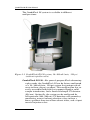
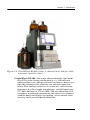
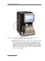
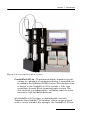
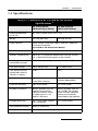
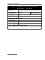
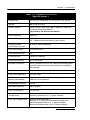
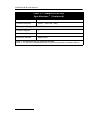
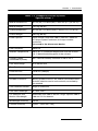
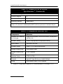
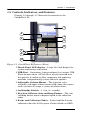
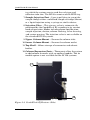
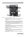
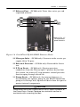
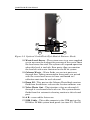
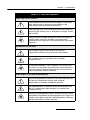
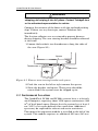
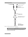
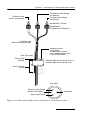
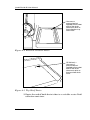
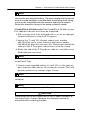
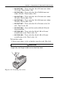
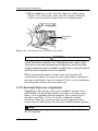
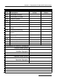

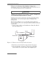
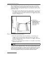
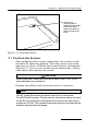
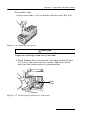
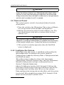
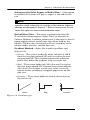
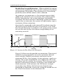
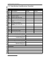
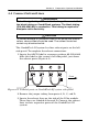
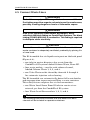
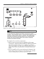
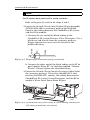
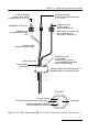
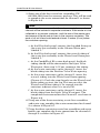
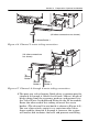
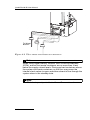
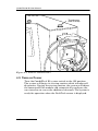
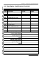

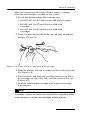
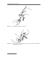
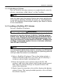


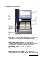
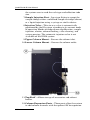
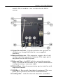
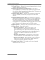
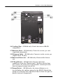
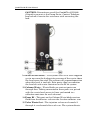
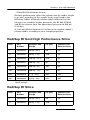
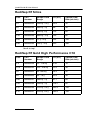
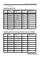
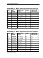
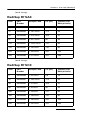
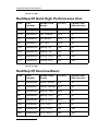
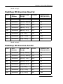
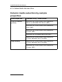
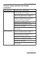
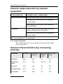
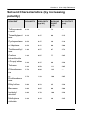
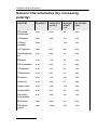
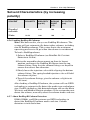

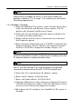
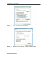
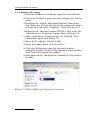
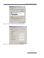
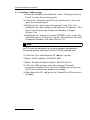
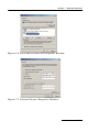
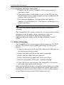
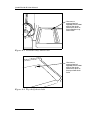
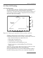
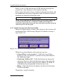
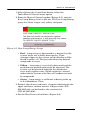
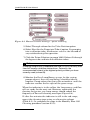
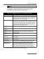

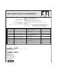
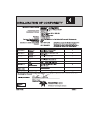
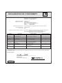
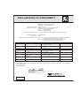
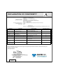
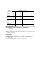


![*Sted Plus UG Jan 2012 [2].indd](http://vs1.manualzilla.com/store/data/005710511_1-f757ed41a0935df19f469c7cee361c5b-150x150.png)