1
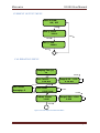
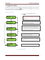
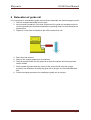
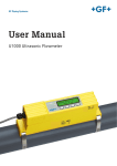
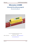
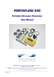
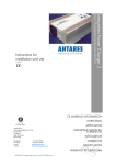
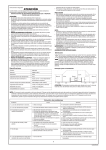
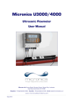
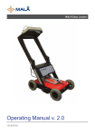
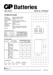
Micronics U1000 User Manual Micronics U1000 Ultrasonic Flowmeter User Manual Micronics Ltd, Knaves Beech Business Centre, Davies Way, Loudwater, High Wycombe, Bucks HP10 9QR Telephone: +44(0)1628 810456 Facsimile: +44(0)1628 531540 E-mail: [email protected] www.micronicsflowmeters.com Issue 2.1 Page 1 Micronics U1000 User Manual Table of Contents 1 General Description ................................................................................................................... 3 2 How does it work? ..................................................................................................................... 4 3 User interface ............................................................................................................................ 5 3.1 4 Key switches ...................................................................................................................... 5 Installing the U1000 ................................................................................................................... 5 4.1 Preparation ........................................................................................................................ 6 4.2 Attaching the U1000 to the pipe ........................................................................................ 7 4.3 Adaptors for small pipes..................................................................................................... 8 4.4 U1000 interface cable ........................................................................................................ 9 4.5 Connecting the U1000 to the Supply .................................................................................. 9 4.6 Pulse Output connection .................................................................................................... 9 4.7 Current Output (When fitted) .......................................................................................... 10 4.8 Cable Screen .................................................................................................................... 10 5 Powering up for the first time .................................................................................................. 10 5.1 How to enter the Pipe ID .................................................................................................. 11 5.2 Pulse output..................................................................................................................... 12 5.2.1 Volumetric mode...................................................................................................... 12 5.2.2 Frequency mode....................................................................................................... 12 5.3 4-20mA Current output (When fitted) .............................................................................. 12 6 Subsequent Power-ON Sequence............................................................................................. 12 7 Password Controlled Menus .................................................................................................... 13 7.1 General procedure for changing menu settings ................................................................ 13 7.1.1 Selection menus ....................................................................................................... 13 7.1.2 Data entry menus ..................................................................................................... 14 7.2 User Password controlled menu structure ........................................................................ 14 8 Diagnostics Menu .................................................................................................................... 19 9 Relocation of guide rail ............................................................................................................ 20 10 Appendix I – U1000 Specification ......................................................................................... 21 11 Appendix II – Default values ................................................................................................. 22 12 Appendix III – Error and Warning Messages ......................................................................... 23 12.1 System errors ................................................................................................................... 23 12.2 Warnings.......................................................................................................................... 23 13 Declaration of conformity……………………………………………………………………………………………………….. 25 Issue 2.1 Page 2 Micronics U1000 User Manual 1 General Description The U1000 is a fixed installation, clamp-on flowmeter that is easy to install and requires the minimum of information to be entered by the user. Unlike other clamp-on flowmeters, the U1000 transducer separation distance is factory preset to a nominal pipe size. Both the electronics and guide rail housings form an integral unit that is attached to the pipe using the supplied jubilee clips. Power to the unit is provided by an external 12 - 24V ac/dc power supply. The U1000 is intended to operate on steel, copper and plastic pipes with ID’s in the range 20mm (0.8”) to 110mm (4”). Compact, rugged and reliable, the U1000 has been designed to provide sustained performance in industrial environments. U1000 standard features include: 2 line x 16 character LCD with backlight 4-key keypad Isolated pulse output Simplified factory configured guide rail and transducer assembly Continuous signal monitoring Password protected menu operation for secure use Operates from external 12 to 24Vac or dc power supplies Optional features 4-20mA current output Small pipe adaptors Typical applications Hot water metering and flow measurement Flow measurement for Heat Metering Chilled water metering and flow measurement Potable water metering and flow measurement Process water metering and flow measurement Ultra pure water metering and flow measurement. Issue 2.1 Page 3 Micronics U1000 User Manual 2 How does it work? The U1000 is a clamp-on, ultrasonic flowmeter that uses a multiple slope transit time algorithm to provide accurate flow measurements. Figure 1 Principle of Transit-Time operation An ultrasonic beam of a given frequency is generated by applying a repetitive voltage pulse to the transducer crystals. This transmission goes first from the Downstream transducer to the Upstream transducer (red) as shown in the upper half of Figure 1. The transmission is then made in the reverse direction, being sent from the Upstream transducer (red) to the Downstream transducer (blue) as shown in the lower half of Figure1. The speed at which the ultrasound is transmitted through the liquid is accelerated slightly by the velocity of the liquid through the pipe. The subsequent time difference T1 – T2 is directly proportional to the liquid flow velocity. Issue 2.1 Page 4 Micronics U1000 User Manual 3 User interface Figure 2 illustrates the U1000 user interface comprising: One 2 line x 16 character LCD with backlight Four tactile key switches Two LED’s Figure 2 U1000 User Interface 3.1 Key switches > Selection key. Allows the user to select between options on the display. V Used to decrement the value of each digit in numeric entry fields. Λ Used to increment the value of each digit in numeric entry fields. Used to enter the selection displayed or terminate the data entry. Pressing this key will take the user to another menu or to the Flow Reading screen. 4-20mA LED is illuminated when the 4-20mA output is ON Pulse LED is illuminated when the Pulse output is ON 4 Installing the U1000 Possible Air Uniform Flow Profile 45° Distorted Flow Profile Guide rail Possible sludge Flow 10 x Diameter Valid transducer location Figure 3 Location of Transducers Issue 2.1 20 x Diameter Flow Page 5 Micronics U1000 User Manual In many applications an even flow velocity profile over a full 360° is unattainable due, for example, to the presence of air turbulence at the top of the flow and possibly sludge at the bottom of the pipe. Experience has shown that the most consistently accurate results are achieved when the transducer guide rails are mounted at 45°with respect to the top of the pipe. The U1000 equipment expects a uniform flow profile, as a distorted flow will produce unpredictable measurement errors. Flow profile distortions can result from upstream disturbance such as bends, tees, valves, pumps and other similar obstructions. To ensure a uniform profile the transducers must be mounted far enough away from any cause of distortion such that it no longer has an effect. To obtain the most accurate results the condition of both the liquid and the pipe must be suitable to allow ultrasound transmission along the predetermined path. It is important that liquid flows uniformly within the length of pipe being monitored, and that the flow profile is not distorted by any upstream or downstream obstructions. This is best achieved by ensuring there is a straight length of pipe upstream of the transducers of at least 20 times the pipe diameter, and 10 times the pipe diameter on the downstream side, as shown in Figure 3. Flow Measurements can be made on shorter lengths of straight pipe, down to 10 diameters upstream and 5 diameters downstream, but when the transducers are mounted this close to any obstruction the resulting errors can be unpredictable. Key Point: Do not expect to obtain accurate results if the transducers are positioned close to any obstruction that distorts the uniformity of the flow profile. Micronics Ltd accepts no responsibility or liability if product has not been installed in accordance with the installation instructions applicable to the product. 4.1 Preparation 1. Before attaching the transducers first ensure that the proposed location satisfies the distance requirements shown in Figure 3 otherwise the resulting accuracy of the flow readings may be affected. 2. Prepare the pipe by degreasing it and removing any loose material or flaking paint in order to obtain the best possible surface. A smooth contact between pipe surface and the face of the transducers is an important factor in achieving a good ultrasound signal strength and therefore maximum accuracy. Issue 2.1 Page 6 Micronics U1000 User Manual 4.2 Attaching the U1000 to the pipe Follow the four steps shown in Figure 4 below to attach the U1000 to the pipe. The grease provided in the syringe is applied to the centre of the sensors as shown above. Clamp guide rail and sensor assembly to pipe, using the supplied banding, and release sensor locking screws. Connect power and sensors to the electronics assembly. Sensor leads can be connected either way round. Click electronic assembly onto guide rails and sensor assembly Figure 4 simple steps to attaching the U1000 on the pipe The locking screws and washers should be kept in case it is necessary to change the location of the guide rail and sensors. See the relocation section for the procedure to do this. Issue 2.1 Page 7 Micronics U1000 User Manual 4.3 Adaptors for small pipes Less than 40mm outside diameter 40 to 60mm outside diameter Greater than 60mm outside diameter Figure 5 Pipe Adaptors Guide rails for small pipes are supplied with adaptors. The diagrams above shows how these are fitted around the pipe. The top pipe adaptor clips into the ends of the guide rail. Issue 2.1 Page 8 Micronics U1000 User Manual 4.4 U1000 interface cable The U1000 interface cable supplied is a 6-core cable and is shown in Figure 6. Un-insulated screen Power Pulse 4-20mA Figure 6. U1000 Interface Cable The polarity of the wires is as follows: 12/24V Input 12/24V Return Pulse Output Pulse Return 4-20mA Output (+) (When fitted) 4-20mA Return (-) (When fitted) The un-insulated wire is the connection to the screen of the cable and should be earthed for full immunity to electrical noise. 4.5 Connecting the U1000 to the Supply The U1000 will operate within the voltage range 12 - 24V ac/dc. Connect the external power supply to the Brown and Blue wires of the six core cable. For full compliance with EMC regulation a 12V supply is recommended for domestic and light industrial applications. 4.6 Pulse Output connection The isolated pulse output is provided by a SPNO MOSFET Relay which has a maximum load current of 500mA and maximum load voltage of 48V AC. The relay also provides 2500V isolation. The pulse output is available at the White and Green wires. Electrically this is a volt free contact closure. Issue 2.1 Page 9 Micronics U1000 User Manual 4.7 Current Output (When fitted) The isolated 4-20mA is a current source and can drive into a maximum load of 620Ω. The 4-20mA current output is available at the Red and Black wires. The polarities are shown in Figure 6. The alarm current due to a flow outside the range specified or due to a loss of signal is set at 3.5mA. 4.8 Cable Screen For full immunity to electrical interference the screen of the cable should be connected to Earth. 5 Powering up for the first time Powering up for the first time will initiate the sequence shown in Figure 7: Figure 7 Initial Power-on sequence 1. The Micronics startup screen is displayed for 5 seconds 2. The user enters the pipe ID (refer to section 5.1) 3. The U1000 checks for a valid signal 4. If a valid signal is found, signal strength and flow magnitude are displayed. The direction of flow when powered up will be set as that for positive flow. The current output and pulse output will relate to the flow in this direction. If the flow is reversed then the flow rate will still be displayed but the activity indication will change from an asterisk to an exclamation mark. No pulses will be generated, and the current will go to the 3.5mA alarm state if the flow is reversed. Issue 2.1 Page 10 Micronics U1000 User Manual 5.1 How to enter the Pipe ID Figure 8 shows the Enter Pipe ID screen after an initial power up. Figure 8 Enter Pipe ID Screen (Metric) Initially, the hundreds unit (050.0) will blink. Press the key to increment the hundreds digit (050.0) in the sequence 0, 1. Press Λ once to increment digit, or hold key down to automatically toggle between 0 and 1. Press the V key to decrement the hundreds digit in the sequence 1, 0. Press once to decrement digit, or hold key down to automatically toggle between 1 and 0. Press the > key to move to the tens digit (050.0). The tens digit should now blink. Increment the tens digit in the sequence 0,1,2,3,4,5,6,7,8,9,0 using the key. Press once to increment digit or hold down to scroll through the numeric sequence. Decrement the tens digit in the V sequence 9,8,7,6,5,4,3,2,1,0,9 using the key. Press once to increment digit or hold down to scroll through the numeric sequence. Press the > key to move to the units digit (050.0). The units digit should now blink. Increment or decrement the units digit in an identical manner to the tens digit described above. Press the > key to move to the decimal digit (050.0). The decimal digit should now blink. Increment or decrement the decimal digit in an identical manner to the tens digit described above. Press the key to enter the Pipe ID numerical value. If any of the parameters need to be changed from the default values, for example different units are required, then the menu system must be activated via the password (see section 7). Issue 2.1 Page 11 Micronics U1000 User Manual 5.2 Pulse output Pulse output can be set up to operate in two modes, namely volumetric and frequency. 5.2.1 Volumetric mode In Volumetric mode, each pulse output represents a measured volume of 10 litres (default value). In Volumetric mode, with the Vol per Pulse set to 1 and the pulse width set to 25ms, the maximum number of pulses that can be output (without storage) is 1/(0.025*2) = 20 pulses per second. If the flow rate in the pipe is such that more than 20 pulses per second are generated, a Pulse Overflow error may eventually occur if the stored number of pulses exceeds 1000. To avoid this, set the Vol per Pulse to 10 litres. 5.2.2 Frequency mode In Frequency mode, the pulse output frequency is proportional to the flow rate within a specified frequency range of 0 – 200Hz. 5.3 4-20mA Current output (When fitted) The default 4-20mA output setting will be ON, and the 4-20mA LED on the keypad will be illuminated. The default flow for 20mA output will be automatically set depending on the pipe size. The default flow for 4mA is 0. This can be changed, see section 7. If the flow reading is greater than that set as the 20mA value, or there is negative flow, or no flow signal can be detected, then an alarm current of 3.5mA will generated. Note: The 4-20mA current output is factory calibrated. 6 Subsequent Power-ON Sequence If the power supply is cycled OFF then ON after the pipe ID has been entered, all subsequent start-ups will use the same configuration as was previously entered. If the configuration needs to be changed for any reason, the user can make use of the passwordcontrolled menu as described in section 7. Issue 2.1 Page 12 Micronics U1000 User Manual 7 Password Controlled Menus The password controlled menu allows the user some flexibility to change the default settings: User Password (71360): Change the dimensions from mm to inches or vice-versa. Change from Flow to Velocity Measurement Change the system units litres/m3 or Impgal/USgal Change the flow units l/s, l/min or gal/s, gal/min or USgals/s, USgals/min Change the default value for Flow at Maximum Current Change the default setting for Flow at Minimum Current Change the Pulse Output type Change the Pulse output parameters 7.1 General procedure for changing menu settings 7.1.1 Selection menus When a password controlled menu is selected the procedure for changing the default setting is the same for all menus. For example, consider the Flow Units menu shown in Figure 9. Flow Units: l/min | l/s Figure 9 Flow Units menu The default value ‘l/min’ will blink to indicate that this is the current setting. To change to ‘l/s’, press the > Press the Issue 2.1 key. Now the ‘l/s’ units will blink to indicate that this is now the selected units. key to confirm the change. Page 13 Micronics U1000 User Manual 7.1.2 Data entry menus Menus containing a numeric value can be altered using the following procedure. For example, consider changing the Flow at maximum current from the default setting 1000 litres as indicated in Figure 10. to 1258 litres. Flow @ 20mA: 1000.0 Figure 10 Example of a Data entry screen Press the > key twice to select the hundreds unit (1000.0) which will now blink Press the Λ Press the key twice to increment the hundreds unit from 0 to 2 (1200.0) Press the > key once to select the tens unit (1200.0) which will now blink Press the Λ Press the > key once to select units (1250.0) which will now blink Press the V key twice to decrement the units from 0 to 8 (1258.0) Press the key five times to increment the hundreds unit from 0 to 5 (1250.0) key to confirm the change All numeric data menus can be changed in this way. 7.2 User Password controlled menu structure Ensure that the instrument is in Flow Reading mode then press the key to go to the user password menu. Enter 71360 using the procedure explained in section 7.1.2. to enter the password. The flow chart shown in Fig.9 shows the user password menu structure. To skip over any menu item that should remain unchanged, simply press the Issue 2.1 key. Page 14 Micronics U1000 User Manual 71360 MENU Invalid & OR No input for 10 seconds Sig: 87% * 246.3 l/min Enter Password: ***** User Menu: Setup Setup Menu Pulse Output Menu Current Output Menu Calibration Menu Totaliser Menu v User Menu: Pulse Output v User Menu: Current Output v v User Menu: Calibration v User Menu: Totals v User Menu: Exit Checking Signals ****** Sig: 87% * 246.3 l/min Figure 11 Main Menu Issue 2.1 Page 15 Micronics U1000 User Manual SETUP MENU Range 0.79 – 4.33 2.000 inches Inches & Select Dimensions: mm | inches Invalid & mm & Range 20 – 110mm 050.0 mm Invalid & Enter Pipe ID: 050.0 mm Enter Pipe ID: 2.000 inches Valid & Valid & Valid & Select Reading: Flow | Vel Vel & (m/s) Select Reading: Flow | Vel Flow & m3 & System Units: litres | m3 Litres & Flow Units m3/min | m3/hr Flow & Flow Units l/min | l/s System Units: Impgal | USgal Vel & (ft/s) Impgal & Flow Units gal/min | gal/hr USgal & Flow Units USgal/min | USgal/hr Figure 12 Setup Menu Issue 2.1 Page 16 Micronics U1000 User Manual PULSE OUTPUT MENU Select Pulse: ON | OFF Range 1 – 200 200 Off & Test mode press V or Λ to generate a pulse On & Invalid & Pulse Type: VOLUME | FREQ Freq & Volume & Max Pulse Freq: 200 Volume per Pulse: 10.0 l Valid & Valid & Invalid & Valid & Max Flow @ Freq: 9999.0 Pulse Width 25 ms Range 3 - 99 25 ms Valid & Valid & Valid & TOTALISER MENU Select Totals ON|OFF On & Reset + Total NO |YES Off & Figure 13 Pulse Output and Totaliser Menu If the Total is turned on then the display will alternate between the flow reading and the total. Either display can be held for 30seconds by pressing the Issue 2.1 > key. Page 17 Micronics U1000 User Manual CURRENT OUTPUT MENU Select 4-20mA: ON | OFF ON & Flow @ 20mA 1000.0 OFF & Valid & Flow @ 4mA 0000.0 Valid & CALIBRATION MENU Damping Time [s]: 20 Invalid & Zero Cut-off: 0.10 m/s V To Set Zero Offset: Averaging…9 Valid & Zero Offset 0.000 l/min Done Range 0.00 – 0.50 0.10 m/s ^ To Clear Invalid & Calibrat. Factor: 1.000 Range 0.500–1.500 1.000 Valid & Figure 14 Current Output and Calibration Menu Issue 2.1 Page 18 Micronics U1000 User Manual 8 Diagnostics Menu The diagnostics menu provides some additional information about the flowmeter and its setup. The V menu can be accessed by pressing the key from the main flow-reading screen. The menu shown below describes the various diagnostics items. DIAGNOSTICS MENU To exit the Diagnostics menu Press Sig: 87% 246.3 N. B. The key board is less responsive in the Diagnostics Menu and longer key presses are required. * l/min v The Estimated TA (Time of Arrival) and Actual TA show the theoretical and measured transit times. These values should be within several per cent of each other. Est.TA 85.64 Act .TA 86.77 > The gain on line one is an indicator of the signal strength. A good signal should have a gain of between 600 to 970. The number in parentheses is the switch setting and should be x1. The second line shows the current time differential between the upstream and downstream signals. Gain 845 (x1) DT 125 ns > > Rev: 05.00.001 S/N: 12547 The unit’s software version is shown on line 1. Line 2 shows the unit’s serial number. > Pulse Frequency 124 If the Frequency pulse option is enabled this screen displays the current pulse output frequency. This is proportional to the flow rate. > Pipe Material Metal The selected pipe material Figure 15 Diagnostics Menu Issue 2.1 Page 19 Micronics U1000 User Manual 9 Relocation of guide rail If it is necessary to relocated the guide rail and sensor assembly use the following procedure 1. Remove complete assembly from the pipe 2. Insert a small screwdriver in the hole at the end of the guide rail moulding and lever up the clip holding the electronics assembly by pressing down on the screwdriver as shown below. 3. Repeat 2 on the other end and then pull off the electronics unit. Figure 16 4. Disconnect the sensors 5. Remove the original grease from the sensors 6. Push the sensor blocks into the guide rail so that the washers and locking screws can be refitted. 7. Place a bead of grease down the centre of the sensor block using the syringe provided. See illustration on fitting the guide rail to the pipe for recommended bead size. 8. Follow the original procedure for installing the guide rail on the pipe. Issue 2.1 Page 20 Micronics U1000 User Manual 10 Appendix I – U1000 Specification Table 1 lists the U1000 Product Specification. General Measuring Technique Measurement channels Timing Resolution Turn down ratio Flow velocity range Applicable Fluid types Accuracy Repeatability Selectable units Languages supported Power input Power consumption Cable Transit time 1 ±50ps 200:1 0.1 to 10m/s bidirectional Clean water with < 3% by volume of particulate content. ±3% of flow reading for flow rate >0.3m/s ±0.5% of measured value Velocity: m/s, ft/s Flow Rate: l/s, l/min, gal/s, gal/min, USgal/s, USgal/min, m3/min, m3/hr Volume: litres, m3, gals, USgals English only 12 – 24V ac or dc 7VA maximum 5m screened 6 core Pulse Output Output Isolation Pulse width Pulse repetition rate Frequency mode Maximum load voltage/current Current Output Output Resolution Maximum load Isolation Alarm current Enclosure Material Fixing Degree of Protection Flammability Rating Dimensions Weight Environmental Pipe temperature Operating temperature (Electronics) Storage temperature Humidity Issue 2.1 Opto-isolated MOSFET volt free normally open contact. 2500V Default value 25ms; programmable range 3 – 99ms Up to 166 pulses/sec (depending on pulse width) 200 Hz maximum 48V AC / 500mA 4 – 20mA 0.1% of full scale 620Ω 1500V opto-isolated 3.5mA Plastic Polycarbonate Pipe mountable IP54 UL94 V-0 250mm x 48mm x 90mm (electronics + guide rail) 0.5kg 0°C to 85°C 0°C to 50°C -10°C to 60°C 90% RH at 50°C Max Page 21 Micronics Display LCD Viewing angle Active area Keypad Format U1000 User Manual 2 line x 16 characters Min 30°, Max 40° 83mm (W) x 18.6mm(H) 4 key tactile feedback membrane keypad 11 Appendix II – Default values The settings will be configured at the factory for either metric or imperial units. Table 2 lists the metric default values. Table 2 System Default Values Parameter Default Value Dimensions mm Flow Rate l/min Pipe size 50 (mm) 4-20mA On, 4-20mA selected Flow at Max Current Equivalent to 2m/s Flow at Min Current 0 Pulse Output On Volume per Pulse 10 litres Pulse Width 25ms Damping 20 seconds Calibration Factor 1.000 Zero Cut-off 0.10m/s Zero Offset 0.000l/min Table 3 lists the default values when Imperial dimensions are selected. Table 3 System Default Values Parameter Default Value Dimensions inches Flow Rate USgal/min Pipe size 2 (inches) 4-20mA On, 4-20mA selected Flow at Max Current Equivalent to 2m/s Flow at Min Current 0 Pulse Output On Volume per Pulse 10 US gallons Pulse Width 25ms Damping 20 seconds Calibration Factor 1.000 Zero Cut-off 0.10m/s Zero Offset 0.000gal/min Issue 2.1 Page 22 Micronics U1000 User Manual 12 Appendix III – Error and Warning Messages 12.1 System errors There are three possible ‘System Error’ messages that can be displayed. These are: 1. Poor Signal. The unit is unable to detect a signal from one or both transducers. If this message persists the sensors will need to be relocated. 2. Pulse Overflow. The value for the ‘Vol per pulse’ is set too low. Increase the Vol per Pulse setting in the password-controlled menu. 3. No BBME: This indicates a unit failure. Reset the unit by turning the power on and off. Contact your supplier if the problem persists. 12.2 Warnings These generally advise the user that the data entered is out of the specified range. 1. When an invalid Pipe ID is entered, the warning message shown below is displayed, prompting the user to enter a value between 20 and 110mm. Range 20 – 110mm 0.000 mm 2. When the 4-20mA current output is turned ON, the Flow at Maximum and Minimum current can be changed under password control. The valid range is 0 – 99999.0 If an invalid value is entered the following warning message is displayed: Range 0 - 99999 0000.0 3. When programming a Frequency Pulse output the frequency is limited to the range 1 to 200 Hz. If an invalid value is entered then the following warning message is displayed. Range 1 - 200 200 4. When programming a Volume Pulse output the pulse width is limited to the range 3 to 99ms. If an invalid value is entered then the following warning message is displayed. Range 3 - 99 0000.0 Issue 2.1 Page 23 Micronics U1000 User Manual 5. When programming the Zero Cut-off this is limited to the range 0.000 to 0.500. If an invalid value is entered then the following warning message is displayed. Range 0.00 – 0.500 0000.0 6. When programming the Calibration Factor this is limited to the range 0.5 to 1.5. If an invalid value is entered then the following warning message is displayed. Range 0.500 – 1.500 0000.0 Issue 2.1 Page 24 Micronics U1000 User Manual Registered Office: Micronics Limited, Knaves Beech Business Centre, Davies Way, Loudwater, Buckinghamshire, HP10 9QR Web site www.micronicsflowmeters.com Tel: +44 (1628) 810456 Fax: +44 (1628) 531540 Issue 2.1 Page 25 Directors E.J. Farnon, M.A. Farnon Registration No. 1289680 V.A.T Registration No. 303 6190 91