1
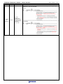
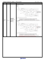
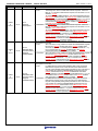
Date: Oct. 01, 2013 RENESAS TECHNICAL UPDATE 1753, Shimonumabe, Nakahara-ku, Kawasaki-shi, Kanagawa 211-8668 Japan Renesas Electronics Corporation Product Category Title MPU/MCU Document No. TN-SH7-A874A/E SH7450 Group, SH7451 Group User's Manual Hardware Errata Rev. B Information Category Technical Notification Reference Document SH7450 Group, SH7451 Group User’s Manual: Hardware Rev. 1.10 (R01UH0286EJ0110) Rev. 1.00 Lot No. Applicable Product SH7450 Group, SH7451 Group We inform you of the corrections of "SH7450 Group, SH7451 Group User’s Manual: Hardware Rev. 1.10 (Published on September 27, 2011)". When you use "SH7450 Group, SH7451 Group User’s Manual: Hardware Rev. 1.10", should be used together the attached errata. In addition, the corrections in the following are also included in the attached errata (Rev. B). - Technical update TN-SH7-A826A/E: Errata (Rev. A) - Technical update TN-SH7-A859A/E: Errata to User’s Manual Regarding CAN Module Attached document: "SH7450 Group, SH7451 Group User’s Manual: Hardware Rev. 1.10" Errata Rev. B – 11 sheets (c) 2013. Renesas Electronics Corporation. All rights reserved. Page 1 of 12 Date: October 1, 2013 RENESAS TECHNICAL UPDATE TN-SH7-A874A/E *Changes/additions are written in reds and underlined. Rev. Page Added in Rev. A Revision History - xiii 26.3.14 CANi Status Register Added in Rev. A Revision History - xv 32.5.1 FlexRay Error Interrupt Register Added in Rev. A Revision History - xvi Appendix A CPU Operation Mode Register Added in Rev. A Added in Rev. A 32-76 38-33 Part 32.7.1 FlexRay CC Status Vector Register Table 38.26 RSPI Timing Contents Revision History: Description of CAN is added. -Page of Previous Edition: 26-49 -Description: Description of the bit 1 (SDST bit) in the CANi Status Register (CiSTR) (i = 0 to 4) is corrected. Error: The SDST bit is set to "1" when at least one SENTDATA bit in the CiMCTLj register is "1" regardless of the value of the CiMIER register. Correction: The SDST bit is set to "1" when at least one SENTDATA bit in the CiMCTLj (j = 32 to 63) register is "1" regardless of the value of the CiMIER register. -Page of Previous Edition: 26-49 -Description: Description of the bit 0 (NDST bit) in the CANi Status Register (CiSTR) (i = 0 to 4) is corrected. Error: The NDST bit is set to "1" when at least one NEWDATA bit in the CiMCTLj register is "1" regardless of the value of the CiMIER register. Correction: The NDST bit is set to "1" when at least one NEWDATA bit in the CiMCTLj (j = 0 to 63) register is "1" regardless of the value of the CiMIER register. Revision History: Description of FlexRay is added. -Page of Previous Edition: 32-17 -Description: Description of the bit 24 (EDB bit) in the FlexRay Error Interrupt Register (FREIR) is corrected. Error: 0: No error detected on channel B RW Correction: 0: No error detected on channel B -Page of Previous Edition: 32-18 -Description: Description of the bit 9 (IIBA bit) in the FlexRay Error Interrupt Register (FREIR) is corrected. Error: 0: No illegal CPU access to Output Buffer occurred 1: Illegal CPU access to Output Buffer occurred Correction: 0: No illegal CPU access to Input Buffer occurred 1: Illegal CPU access to Input Buffer occurred Revision History: Description of Appendix A is added. -Page of Previous Edition: A-1 -Description: Value after reset of the bit 5 (RABD bit) in the CPU Operation Mode Register (CPUOPM) is revised. Error: Value after reset of the RABD bit is "1" Correction: Value after reset of the RABD bit is " 0" Description of the bit 29 to 24 (PSL5 to PSL0 bit) in the FlexRay CC Status Vector Register (FRCCSV) is corrected. Error: Set to B’000100 when leaving HALT state. Correction: Set to B’000000 when leaving HALT state. Table 38.26 RSPI Timing : Incorrect description is corrected. Error: Item Data input setup time Symbol Slave tSU Min. 25 + 2 x tcyc Max. Unit - ns Max. Unit - ns Figures 38.28 to 38.31 Correction: Item Data input setup time Symbol Slave tSU Min. 25 - 2 x tcyc Figures 38.28 to 38.31 Page 2 of 12 Date: October 1, 2013 RENESAS TECHNICAL UPDATE TN-SH7-A874A/E Rev. Added in Rev. A Page 38-35 Part Figure 38.30 RSPI Timing (Slave, CPHA = "0") Contents Figure 38.30 RSPI Timing (Slave, CPHA = "0") : Incorrect description is corrected. O in a figure shows the added part. Error: Correction: Table 38.29 DRI Timing (When Special Mode is On) : Incorrect description is corrected. Error: Item Symbol Min. Max. Unit Figures DIN2 to DIN4 sampling tar 8 38.33 to ns Added in Rev. A 38-38 Table 38.29 DRI Timing (When Special Mode is On) edge undefined time before DIN1 initialization level release (when direct reset is selected) DIN2 to DIN4 sampling edge undefined time before DIN1 initialization level release Correction: Item DIN2 to DIN4 sampling edge undefined time before DIN1 initialization level release DIN2 to DIN4 sampling edge undefined time after DIN1 initialization level release 38.36 tbr Symbol 12 - Min. tar 8 tbr 12 ns Max. - - Unit ns Figures 38.33 to 38.36 ns Table 38.35 AUDR Module Timing (PVcc = 5.0 V) : Incorrect description is corrected. Error: Added in Rev. A 38-46 Table 38.35 AUDR Module Timing (PVcc = 5.0 V) Item AUDRD output delay time before AUDRCLK Symbol td(AUDRCLKHAUDRD) Min. Max. Unit - 35 ns Symbol td(AUDRCLKHAUDRD) Min. Max. Unit - 35 ns Figures 38.46 Correction: Item AUDRD output delay time after AUDRCLK Figures 38.46 Page 3 of 12 Date: October 1, 2013 RENESAS TECHNICAL UPDATE TN-SH7-A874A/E Rev. Added in Rev. A Page 38-47 Part Table 38.36 AUDR Module Timing (PVcc = 3.3 V) Contents Table 38.36 AUDR Module Timing (PVcc = 3.3 V) : Incorrect description is corrected. Error: Item AUDRD output delay time before AUDRCLK Added in Rev. B Added in Rev. B 12-8 12.3.2 Flash Access Status Register (FASTAT) 12-23 Figure 12.8 Command State Transitions in ROM Read Mode and P/E Mode 12-36 12.9.4 Reset during Programming or Erasure Min. Max. Unit - 40 ns Symbol td(AUDRCLKHAUDRD) Min. Max. Unit - 40 ns Figures 38.46 Correction: Item AUDRD output delay time after AUDRCLK Added in Rev. B Symbol td(AUDRCLKHAUDRD) Figures 38.46 Description of the bit 7 (ROMAE bit) in the Flash Access Status Register (FASTAT) is corrected. Error: An access command is issued to an address other than ROM program/erase addresses H'FD80 0000 to H'FD9F FFFF when the user boot MAT is selected. Correction: An access command is issued to an address other than ROM program/erase addresses H'FD80 0000 to H'FD80 7FFF when the user boot MAT is selected. Figure 12.8 Command State Transitions in ROM Read Mode and P/E Mode : Incorrect description is corrected. Error: Correction: Description of Reset during Programming or Erasure is added. -Description: When a hardware reset by "L" level input to the RESET# pin, switching the power off, or a FCU reset by setting the FRESET bit in the FRESETR register, is executed during programming or erasure, the whole data in the programming or erasure area becomes undefined. When the data in an area have become undefined, erase the area before using it again. Page 4 of 12 RENESAS TECHNICAL UPDATE TN-SH7-A874A/E Rev. Added in Rev. B Added in Rev. B Added in Rev. B Page Part 24-9 24.3.3 RSPIi Pin Control Register (SPiPCR) 24-24 24.3.13 RSPIi Command Registers 0 to 3 (SPiCMD0 to SPiCMD3) 24-28 Table 24.7 MOSIi Signal Value Determination during SSL Negation Period Date: October 1, 2013 Contents Description of the bit 5 (MOIFE bit) in the RSPIi Pin Control Register (SPiPCR) is corrected. Error: - When the MOIFE bit is cleared to "0", RSPIi outputs on the MOSIi pin the last data unit from the previous serial transfer during the SSL negation period. - 0: MOSIi output value equals final data from previous transfer Correction: - When the MOIFE bit is cleared to "0", RSPIi outputs the final output level of the previous serial transfer to the MOSIi pin during the SSL negation period (When the CPHA bit is "0", MOSIi output value is undefined). - 0: MOSIi output value equals final output level from previous transfer (When the CPHA bit is "0", MOSIi output value is undefined) Description of the bit 13 (SPNDEN bit) in the RSPIi Command Registers 0 to 3 (SPiCMD0 to SPiCMD3) is corrected. Error: - If the SPNDEN bit is "0", the RSPIi sets the next-access delay to 1 RSPCK. - 0: A next-access delay of 1 RSPCK Correction: - If the SPNDEN bit is "0", the RSPIi sets the next-access delay to 1 RSPCK + 2 Pck. - 0: A next-access delay of 1 RSPCK + 2 Pck Table 24.7 MOSIi Signal Value Determination during SSL Negation Period : Incorrect description is corrected. Error: MOIFE MOIFV MOSIi Signal Value during SSL Negation Period 0 0, 1 Final data from previous transfer 1 0 Always "L" 1 1 Always "H" Correction: MOIFE MOIFV 0 0, 1 1 1 0 1 MOSIi Signal Value during SSL Negation Period Final output level of the previous transfer (When the CPHA bit is "0", MOSIi output value is undefined) Always "L" Always "H" Figure 24.11 RSPI Transfer Format (CPHA = "0") : Incorrect description is corrected. Error: Added in Rev. B 24-34 Figure 24.11 RSPI Transfer Format (CPHA = "0") Correction: Page 5 of 12 Date: October 1, 2013 RENESAS TECHNICAL UPDATE TN-SH7-A874A/E Rev. Added in Rev. B Page 24-34 Part Figure 24.12 RSPI Transfer Format (CPHA = "1") Contents Figure 24.12 RSPI Transfer Format (CPHA = "1") : Incorrect description is corrected. Error: Correction: The values after reset of the CANi Clock Select Register (CiCLKR) (i = 0 to 4) are corrected. Error: Register Name Abbreviation CAN0 Clock Select Register C0CLKR : 26-5 Table 26.3 Register Configuration : 8, 16, 32 26-16 : H'00 : : H'FFFF 8847 : H'00 : CAN4 Clock Select Register C4CLKR : H'FFFF 7847 H'00 : CAN3 Clock Select Register C3CLKR Added in Rev. B Size H'FFFF 6847 : CAN2 Clock Select Register C2CLKR : P4 Address H'00 : CAN1 Clock Select Register C1CLKR : After Reset : H'FFFF 9847 : : : Page : 8, 16, 32 26-16 : : 8, 16, 32 26-16 : : 8, 16, 32 26-16 : : H'00 H'FFFF A847 8, 16, 32 26-16 After Reset P4 Address Size Correction: Register Name Abbreviation CAN0 Clock Select Register C0CLKR : : CAN1 Clock Select Register C1CLKR : : CAN2 Clock Select Register C2CLKR : : CAN3 Clock Select Register C3CLKR : : CAN4 Clock Select Register C4CLKR Undefined H'FFFF 6847 : : Undefined H'FFFF 7847 : : Undefined H'FFFF 8847 : : Undefined H'FFFF 9847 : : Undefined H'FFFF A847 Page 8, 16, 32 26-16 : : 8, 16, 32 26-16 : : 8, 16, 32 26-16 : : 8, 16, 32 26-16 : : 8, 16, 32 26-16 Page 6 of 12 Date: October 1, 2013 RENESAS TECHNICAL UPDATE TN-SH7-A874A/E Rev. Page Part Contents The value after reset of the bit 4 in the CANi Clock Select Register (CiCLKR) (i = 0 to 4) is corrected. Error: Bit: After Reset: 7 6 5 4 3 2 1 0 CCLKS 0 0 0 0 0 0 0 0 <After Reset: H'00> Added in Rev. B 26-16 26.3.2 CANi Clock Select Register (CiCLKR) (i = 0 to 4) Bit 4 Abbreviation After Reset 0 R ? W 0 Description Reserved Bit Should be written with "0" and read as undefined value. Correction: Bit: After Reset: 7 6 5 4 3 2 1 0 CCLKS 0 0 0 Undefined 0 0 0 0 <After Reset: Undefined> Bit 4 Abbreviation After Reset Undefined R ? W 0 Description Reserved Bit Should be written with "0" and read as undefined value. Setting value of the bit 7 to 0 (CiRFPCR bit) in the CANi Receive FIFO Pointer Control Register (CiRFPCR) (i = 0 to 4) is corrected. Error: Added in Rev. B 26-42 26.3.11 CANi Receive FIFO Pointer Control Register (CiRFPCR) (i = 0 to 4) Bit 7 to 0 Abbreviation CiRFPCR After Reset Undefined R R W W Description The CPU-side pointer for the receive FIFO is incremented by writing "H'FF" After Reset Undefined R ? W W Description The CPU-side pointer for the receive FIFO is incremented by writing "H'FF" Correction: Bit 7 to 0 Abbreviation CiRFPCR Setting value of the bit 7 to 0 (CiTFPCR bit) in the CANi Transmit FIFO Pointer Control Register (CiTFPCR) (i = 0 to 4) is corrected. Error: Added in Rev. B 26-46 26.3.13 CANi Transmit FIFO Pointer Control Register (CiTFPCR) (i = 0 to 4) Bit 7 to 0 Abbreviation CiTFPCR After Reset Undefined R R W W Description The CPU-side pointer for the transmit FIFO is incremented by writing "H'FF" After Reset Undefined R ? W W Description The CPU-side pointer for the transmit FIFO is incremented by writing "H'FF" Correction: Bit 7 to 0 Abbreviation CiTFPCR Page 7 of 12 RENESAS TECHNICAL UPDATE TN-SH7-A874A/E Rev. Added in Rev. B Page 26-57 Part 26.3.20 CANi Error Interrupt Factor Judge Register (CiEIFR) (i = 0 to 4) Date: October 1, 2013 Contents Description of the bit 7 (BLIF bit) in the CANi Error Interrupt Factor Judge Register (CiEIFR) (i = 0 to 4) is corrected. Error: Correction: Page 8 of 12 RENESAS TECHNICAL UPDATE TN-SH7-A874A/E Rev. Added in Rev. B Page 26-72 Part Figure 26.9 Transition between CAN Operating Modes (i = 0 to 4) Date: October 1, 2013 Contents Figure 26.9 Transition between CAN Operating Modes (i = 0 to 4) : Incorrect description is corrected. Error: Correction: Page 9 of 12 RENESAS TECHNICAL UPDATE TN-SH7-A874A/E Rev. Added in Rev. B Page 26-74 Part Table 26.9 Operation in CAN Reset Mode and CAN Halt Mode Date: October 1, 2013 Contents Table 26.9 Operation in CAN Reset Mode and CAN Halt Mode : Incorrect description is corrected. Error: Correction: Page 10 of 12 RENESAS TECHNICAL UPDATE TN-SH7-A874A/E Rev. Page Added in Rev. B 28-11 28.3 Register Descriptions 28-16 28.3.4 DRI0DIN DMA Transfer Enable Register (DRI0DINDEN) 28-21 28.3.8 DRI0DEC DMA Transfer Enable Register (DRI0DECDEN) Added in Rev. B Added in Rev. B Part Date: October 1, 2013 Contents 28.3 Register Descriptions : Incorrect description is corrected. Error: These flags are used to enable DMA transfer requests. Set these flags to "1" to enable a DMA transfer request, and set them to "0" to disable a request. To prevent incorrect DMA operation, only rewrite these bits from the DMA transfer masked state to the DMA transfer enabled state when DRI acquisition is enabled (DRIiDCAPCNT.DCPEN bit = "1"). Do not rewrite from the DMA transfer enabled state to the DMA transfer masked state when DRI acquisition is enabled, since that can result in a DMA request not being handled. Correction: These flags are used to enable DMA transfer requests. Set these flags to "1" to enable a DMA transfer request, and set them to "0" to disable a DMA transfer request. To prevent incorrect DMA operation, only rewrite these bits from the DMA transfer request masked state to the DMA transfer request enabled state when DRI acquisition is enabled (DRIiDCAPCNT.DCPEN bit = "1"). Do not rewrite from the DMA transfer request enabled state to the DMA transfer request masked state when DRI acquisition is enabled, since that can result in a DMA transfer request not being handled. 28.3.4 DRI0DIN DMA Transfer Enable Register (DRI0DINDEN) : Incorrect description is corrected. Error: Also note that it is only possible to rewrite the DRI0DINDEN register bits from the transfer masked state to the transfer enabled state when DRI acquisition is enabled (DRIiDCAPCNT.DCPEN bit = "1"). Do not rewrite from the transfer enabled state to the transfer masked state when DRI acquisition is enabled. Correction: Also note that it is only possible to rewrite the DRI0DINDEN register bits from the DMA transfer request masked state to the DMA transfer request enabled state when DRI acquisition is enabled (DRIiDCAPCNT.DCPEN bit = "1"). Do not rewrite from the DMA transfer request enabled state to the DMA transfer request masked state when DRI acquisition is enabled. 28.3.8 DRI0DEC DMA Transfer Enable Register (DRI0DECDEN) : Incorrect description is corrected. Error: If a DMA transfer request mask (disable) setting and an internal DMA transfer request occur at the same time, the DMA transfer request mask (disable) setting takes precedence. Also note that it is only possible to rewrite the DRI0DECDEN register bits from the transfer masked state to the transfer enabled state when DEC counter operation is enabled (DRIiDECnCNT.DECnEN bit = "1"). Do not rewrite from the transfer enabled state to the transfer masked state when DEC counter operation is enabled. Correction: If a DMA transfer request mask (disable) setting and an internal DMA transfer request occur at the same time, the DMA transfer request mask (disable) setting takes precedence. Also note that it is only possible to rewrite the DRI0DECDEN register bits from the DMA transfer request masked state to the DMA transfer request enabled state when DEC counter operation is enabled (DRIiDECnCNT.DECnEN bit = "1"). Do not rewrite from the DMA transfer request enabled state to the DMA transfer request masked state when DEC counter operation is enabled. Page 11 of 12 Date: October 1, 2013 RENESAS TECHNICAL UPDATE TN-SH7-A874A/E Rev. Added in Rev. B Added in Rev. B Added in Rev. B Page Part 28-27 28.3.12 DRI0 DMA Transfer Enable Register (DRI0TRMDEN) 32-13 32.4.1 FlexRay Operation Control Register (FXROC) 32-139 32.12.5 Configuration of NIT Start and Offset Correction Start Contents 28.3.12 DRI0 DMA Transfer Enable Register (DRI0TRMDEN) : Incorrect description is corrected. Error: Controls the enabled/disabled states for DRI0 transfer related DMA transfer requests. If one of these bits is set to "1", the corresponding DMA transfer request signal output is enabled. If a DMA transfer mask (disable) is set at the same time as an internal DMA transfer request, the DMA transfer mask (disable) takes precedence. Also note that when DRI acquisition is enabled (DRIiDCAPCNT.DCPEN bit = "1"), the DRI0TRMDEN register may only be rewritten from the transfer masked state to the transfer enabled state. Do not rewrite any bits in this register from the transfer enabled state to the transfer masked state when DRI acquisition is enabled. Correction: Controls the enabled/disabled states for DRI0 transfer related DMA transfer requests. If one of these bits is set to "1", the corresponding DMA transfer request signal output is enabled. If a DMA transfer mask (disable) is set at the same time as an internal DMA transfer request, the DMA transfer mask (disable) takes precedence. Also note that when DRI acquisition is enabled (DRIiDCAPCNT.DCPEN bit = "1"), the DRI0TRMDEN register may only be rewritten from the DMA transfer request masked state to the DMA transfer request enabled state. Do not rewrite any bits in this register from the DMA transfer request enabled state to the DMA transfer request masked state when DRI acquisition is enabled. Description of the bit 2 (FBSEN bit) in the FlexRay Operation Control Register (FXROC) is corrected. Error: - FRNVMn - FRNVMn Correction: - FRNMVn - FRNMVn 32.12.5 Configuration of NIT Start and Offset Correction Start : Incorrect description is corrected. Error: For the FlexRay module the offset correction start is required to be the OCS bit in the FRGTUC4 register σ the NIT bit int the FRGTUC4 register + 1 = k+1. Correction: For the FlexRay module the offset correction start is required to be the OCS bit in the FRGTUC4 register the NIT bit in the FRGTUC4 register + 1 = k+1. Table 32.8 State Transitions of FlexRay overall state Machine : Incorrect description is corrected. Error: T# T1 T2 Added in Rev. B 32-145 Table 32.8 State Transitions of FlexRay overall state Machine : T15 Condition Hard reset Command CONFIG, bits CMD3 to CMD0 in the FRSUCC1 register = B'0001 : Command CONFIG, bits CMD3 to CMD0 in the FRSUCC1 register = B'0001 From All states DEFALT_CONFIG : To DEFALT_CONFIG CONFIG HALT : DEFALT_CONFIG From All states DEFAULT_CONFIG To DEFAULT_CONFIG CONFIG : : DEFAULT_CONFIG Correction: T# T1 T2 : T15 Condition Hard reset Command CONFIG, bits CMD3 to CMD0 in the FRSUCC1 register = B'0001 : Command CONFIG, bits CMD3 to CMD0 in the FRSUCC1 register = B'0001 HALT Page 12 of 12