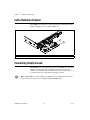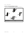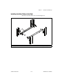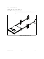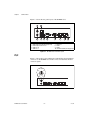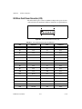
1
NI RMC-8355 User Manual NI RMC-8355 User Manual September 2012 373693B-01 Support Worldwide Technical Support and Product Information ni.com Worldwide Offices Visit ni.com/niglobal to access the branch office Web sites, which provide up-to-date contact information, support phone numbers, email addresses, and current events. National Instruments Corporate Headquarters 11500 North Mopac Expressway Austin, Texas 78759-3504 USA Tel: 512 683 0100 For further support information, refer to the Technical Support and Professional Services appendix. To comment on National Instruments documentation, refer to the National Instruments Web site at ni.com/info and enter the Info Code feedback. © 2012 National Instruments. All rights reserved. Important Information Warranty The NI RMC-8355 is warranted against defects in materials and workmanship for a period of one year from the date of shipment, as evidenced by receipts or other documentation. National Instruments will, at its option, repair or replace equipment that proves to be defective during the warranty period. This warranty includes parts and labor. The media on which you receive National Instruments software are warranted not to fail to execute programming instructions, due to defects in materials and workmanship, for a period of 90 days from date of shipment, as evidenced by receipts or other documentation. National Instruments will, at its option, repair or replace software media that do not execute programming instructions if National Instruments receives notice of such defects during the warranty period. National Instruments does not warrant that the operation of the software shall be uninterrupted or error free. A Return Material Authorization (RMA) number must be obtained from the factory and clearly marked on the outside of the package before any equipment will be accepted for warranty work. National Instruments will pay the shipping costs of returning to the owner parts which are covered by warranty. National Instruments believes that the information in this document is accurate. The document has been carefully reviewed for technical accuracy. In the event that technical or typographical errors exist, National Instruments reserves the right to make changes to subsequent editions of this document without prior notice to holders of this edition. The reader should consult National Instruments if errors are suspected. In no event shall National Instruments be liable for any damages arising out of or related to this document or the information contained in it. EXCEPT AS SPECIFIED HEREIN, NATIONAL INSTRUMENTS MAKES NO WARRANTIES, EXPRESS OR IMPLIED, AND SPECIFICALLY DISCLAIMS ANY WARRANTY OF MERCHANTABILITY OR FITNESS FOR A PARTICULAR PURPOSE. CUSTOMER’S RIGHT TO RECOVER DAMAGES CAUSED BY FAULT OR NEGLIGENCE ON THE PART OF NATIONAL INSTRUMENTS SHALL BE LIMITED TO THE AMOUNT THERETOFORE PAID BY THE CUSTOMER. NATIONAL INSTRUMENTS WILL NOT BE LIABLE FOR DAMAGES RESULTING FROM LOSS OF DATA, PROFITS, USE OF PRODUCTS, OR INCIDENTAL OR CONSEQUENTIAL DAMAGES, EVEN IF ADVISED OF THE POSSIBILITY THEREOF. This limitation of the liability of National Instruments will apply regardless of the form of action, whether in contract or tort, including negligence. Any action against National Instruments must be brought within one year after the cause of action accrues. National Instruments shall not be liable for any delay in performance due to causes beyond its reasonable control. The warranty provided herein does not cover damages, defects, malfunctions, or service failures caused by owner’s failure to follow the National Instruments installation, operation, or maintenance instructions; owner’s modification of the product; owner’s abuse, misuse, or negligent acts; and power failure or surges, fire, flood, accident, actions of third parties, or other events outside reasonable control. Copyright Under the copyright laws, this publication may not be reproduced or transmitted in any form, electronic or mechanical, including photocopying, recording, storing in an information retrieval system, or translating, in whole or in part, without the prior written consent of National Instruments Corporation. National Instruments respects the intellectual property of others, and we ask our users to do the same. NI software is protected by copyright and other intellectual property laws. Where NI software may be used to reproduce software or other materials belonging to others, you may use NI software only to reproduce materials that you may reproduce in accordance with the terms of any applicable license or other legal restriction. End-User License Agreements and Third-Party Legal Notices You can find end-user license agreements (EULAs) and third-party legal notices in the following locations: • Notices are located in the <National Instruments>\_Legal Information and <National Instruments> directories. • EULAs are located in the <National Instruments>\Shared\MDF\Legal\license directory. • Review <National Instruments>\_Legal Information.txt for more information on including legal information in installers built with NI products. Trademarks CVI, LabVIEW, National Instruments, NI, ni.com, the National Instruments corporate logo, and the Eagle logo are trademarks of National Instruments Corporation. Refer to the Trademark Information at ni.com/trademarks for other National Instruments trademarks. The mark LabWindows is used under a license from Microsoft Corporation. Windows is a registered trademark of Microsoft Corporation in the United States and other countries. Other product and company names mentioned herein are trademarks or trade names of their respective companies. Members of the National Instruments Alliance Partner Program are business entities independent from National Instruments and have no agency, partnership, or joint-venture relationship with National Instruments. Patents For patents covering National Instruments products/technology, refer to the appropriate location: Help»Patents in your software, the patents.txt file on your media, or the National Instruments Patent Notice at ni.com/patents. Export Compliance Information Refer to the Export Compliance Information at ni.com/legal/export-compliance for the National Instruments global trade compliance policy and how to obtain relevant HTS codes, ECCNs, and other import/export data. WARNING REGARDING USE OF NATIONAL INSTRUMENTS PRODUCTS (1) NATIONAL INSTRUMENTS PRODUCTS ARE NOT DESIGNED WITH COMPONENTS AND TESTING FOR A LEVEL OF RELIABILITY SUITABLE FOR USE IN OR IN CONNECTION WITH SURGICAL IMPLANTS OR AS CRITICAL COMPONENTS IN ANY LIFE SUPPORT SYSTEMS WHOSE FAILURE TO PERFORM CAN REASONABLY BE EXPECTED TO CAUSE SIGNIFICANT INJURY TO A HUMAN. (2) IN ANY APPLICATION, INCLUDING THE ABOVE, RELIABILITY OF OPERATION OF THE SOFTWARE PRODUCTS CAN BE IMPAIRED BY ADVERSE FACTORS, INCLUDING BUT NOT LIMITED TO FLUCTUATIONS IN ELECTRICAL POWER SUPPLY, COMPUTER HARDWARE MALFUNCTIONS, COMPUTER OPERATING SYSTEM SOFTWARE FITNESS, FITNESS OF COMPILERS AND DEVELOPMENT SOFTWARE USED TO DEVELOP AN APPLICATION, INSTALLATION ERRORS, SOFTWARE AND HARDWARE COMPATIBILITY PROBLEMS, MALFUNCTIONS OR FAILURES OF ELECTRONIC MONITORING OR CONTROL DEVICES, TRANSIENT FAILURES OF ELECTRONIC SYSTEMS (HARDWARE AND/OR SOFTWARE), UNANTICIPATED USES OR MISUSES, OR ERRORS ON THE PART OF THE USER OR APPLICATIONS DESIGNER (ADVERSE FACTORS SUCH AS THESE ARE HEREAFTER COLLECTIVELY TERMED “SYSTEM FAILURES”). ANY APPLICATION WHERE A SYSTEM FAILURE WOULD CREATE A RISK OF HARM TO PROPERTY OR PERSONS (INCLUDING THE RISK OF BODILY INJURY AND DEATH) SHOULD NOT BE RELIANT SOLELY UPON ONE FORM OF ELECTRONIC SYSTEM DUE TO THE RISK OF SYSTEM FAILURE. TO AVOID DAMAGE, INJURY, OR DEATH, THE USER OR APPLICATION DESIGNER MUST TAKE REASONABLY PRUDENT STEPS TO PROTECT AGAINST SYSTEM FAILURES, INCLUDING BUT NOT LIMITED TO BACK-UP OR SHUT DOWN MECHANISMS. BECAUSE EACH END-USER SYSTEM IS CUSTOMIZED AND DIFFERS FROM NATIONAL INSTRUMENTS' TESTING PLATFORMS AND BECAUSE A USER OR APPLICATION DESIGNER MAY USE NATIONAL INSTRUMENTS PRODUCTS IN COMBINATION WITH OTHER PRODUCTS IN A MANNER NOT EVALUATED OR CONTEMPLATED BY NATIONAL INSTRUMENTS, THE USER OR APPLICATION DESIGNER IS ULTIMATELY RESPONSIBLE FOR VERIFYING AND VALIDATING THE SUITABILITY OF NATIONAL INSTRUMENTS PRODUCTS WHENEVER NATIONAL INSTRUMENTS PRODUCTS ARE INCORPORATED IN A SYSTEM OR APPLICATION, INCLUDING, WITHOUT LIMITATION, THE APPROPRIATE DESIGN, PROCESS AND SAFETY LEVEL OF SUCH SYSTEM OR APPLICATION. Compliance Electromagnetic Compatibility Information This hardware has been tested and found to comply with the applicable regulatory requirements and limits for electromagnetic compatibility (EMC) as indicated in the hardware’s Declaration of Conformity (DoC)1. These requirements and limits are designed to provide reasonable protection against harmful interference when the hardware is operated in the intended electromagnetic environment. In special cases, for example when either highly sensitive or noisy hardware is being used in close proximity, additional mitigation measures may have to be employed to minimize the potential for electromagnetic interference. While this hardware is compliant with the applicable regulatory EMC requirements, there is no guarantee that interference will not occur in a particular installation. To minimize the potential for the hardware to cause interference to radio and television reception or to experience unacceptable performance degradation, install and use this hardware in strict accordance with the instructions in the hardware documentation and the DoC1. If this hardware does cause interference with licensed radio communications services or other nearby electronics, which can be determined by turning the hardware off and on, you are encouraged to try to correct the interference by one or more of the following measures: • Reorient the antenna of the receiver (the device suffering interference). • Relocate the transmitter (the device generating interference) with respect to the receiver. • Plug the transmitter into a different outlet so that the transmitter and the receiver are on different branch circuits. Some hardware may require the use of a metal, shielded enclosure (windowless version) to meet the EMC requirements for special EMC environments such as, for marine use or in heavy industrial areas. Refer to the hardware’s user documentation and the DoC1 for product installation requirements. When the hardware is connected to a test object or to test leads, the system may become more sensitive to disturbances or may cause interference in the local electromagnetic environment. Operation of this hardware in a residential area is likely to cause harmful interference. Users are required to correct the interference at their own expense or cease operation of the hardware. Changes or modifications not expressly approved by National Instruments could void the user’s right to operate the hardware under the local regulatory rules. 1 The Declaration of Conformity (DoC) contains important EMC compliance information and instructions for the user or installer. To obtain the DoC for this product, visit ni.com/certification, search by model number or product line, and click the appropriate link in the Certification column. Contents About This Manual Conventions ...................................................................................................................xi Related Documentation..................................................................................................xii Chapter 1 Getting Started Unpacking ......................................................................................................................1-1 What You Need to Get Started ......................................................................................1-1 NI RMC-8355 Overview ...............................................................................................1-2 Key Features ..................................................................................................................1-2 Mainboard Features .........................................................................................1-2 CPU...................................................................................................1-2 Chipset ..............................................................................................1-2 Memory .............................................................................................1-3 Slots...................................................................................................1-3 Video.................................................................................................1-3 HDD ..................................................................................................1-3 DVD-R/W .........................................................................................1-3 Onboard LAN ...................................................................................1-3 Onboard I/O ......................................................................................1-3 Power Supply ....................................................................................1-4 Fan.....................................................................................................1-4 Power Management Features ............................................................1-4 Front Panel LEDs..............................................................................1-4 System Management .........................................................................1-4 NI RMC-8355 Description ............................................................................................1-5 Upgrade/Optional Equipment ........................................................................................1-6 Memory Upgrades ...........................................................................................1-6 Upgrade Options..............................................................................................1-6 National Instruments Software ......................................................................................1-7 Chapter 2 Installation and BIOS Setup Safety Information .........................................................................................................2-1 Chassis Cooling Considerations ....................................................................................2-2 Providing Adequate Clearance ........................................................................2-2 Installation .....................................................................................................................2-3 Cable Retention Bracket ................................................................................................2-4 © National Instruments vii NI RMC-8355 User Manual Contents Connecting Safety Ground ............................................................................................ 2-4 Connecting to Power Source ......................................................................................... 2-5 BIOS Setup.................................................................................................................... 2-5 Main BIOS Setup Menu.................................................................................. 2-5 System Overview.............................................................................. 2-6 SuperMicro X8DTU ......................................................................... 2-6 Processor........................................................................................... 2-6 System Memory................................................................................ 2-7 Advanced Setup Configurations ..................................................................... 2-7 Boot Features .................................................................................... 2-8 Power Configuration......................................................................... 2-9 Processor and Clock Options............................................................ 2-9 Advanced Chipset Control................................................................ 2-12 North Bridge Configuration.............................................................. 2-14 South Bridge Configuration.............................................................. 2-16 IDE/SATA Configuration................................................................. 2-17 PCI/PnP Configuration ..................................................................... 2-20 Super IO Device Configuration ........................................................ 2-21 Remote Access Configuration .......................................................... 2-22 Hardware Health Event Monitoring ................................................. 2-23 ACPI Configuration.......................................................................... 2-25 IPMI Configuration (Not Supported) ............................................... 2-27 View BMC System Event Log ......................................................... 2-27 Set LAN Configuration .................................................................... 2-28 Event Log Configuration .................................................................. 2-29 Security Settings ............................................................................................. 2-30 Supervisor Password......................................................................... 2-30 Change Supervisor Password ........................................................... 2-30 User Access Level ............................................................................ 2-31 Change User Password ..................................................................... 2-31 Clear User Password......................................................................... 2-31 Password Check................................................................................ 2-31 Boot Sector Virus Protection ............................................................ 2-31 Clear User Password......................................................................... 2-31 Password Check................................................................................ 2-31 Boot Configuration ......................................................................................... 2-32 Boot Device Priority ......................................................................... 2-32 Removable Drives ............................................................................ 2-32 CD/DVD Drives ............................................................................... 2-32 USB Drives....................................................................................... 2-33 Network Drives................................................................................. 2-33 Exit Options .................................................................................................... 2-33 Save Changes and Exit ..................................................................... 2-33 Discard Changes and Exit................................................................. 2-34 NI RMC-8355 User Manual viii ni.com Contents Discard Changes ...............................................................................2-34 Load Optimal Defaults......................................................................2-34 Load Fail-Safe Defaults ....................................................................2-34 BIOS Error Beep Codes ..................................................................................2-34 OS Reinstallation and Recovery ....................................................................................2-35 Cleaning .........................................................................................................................2-36 Exterior Cleaning.............................................................................................2-36 Rack Mounting ..............................................................................................................2-36 Installing the Inner Slides................................................................................2-37 Installing the Slide Mounting Brackets in the Rack........................................2-38 Installing the Outer Slides in the Rack ............................................................2-39 Installing the Chassis into the Rack.................................................................2-40 Chapter 3 I/O Information Rear Panel Connectors...................................................................................................3-1 PS/2..................................................................................................................3-2 Universal Serial Bus ........................................................................................3-3 Serial................................................................................................................3-4 VGA ................................................................................................................3-5 Ethernet............................................................................................................3-7 MXI-Express Connectors ..............................................................................................3-8 Chapter 4 Common Configuration Questions General Questions..........................................................................................................4-1 Boot Options ..................................................................................................................4-2 Chassis Configuration....................................................................................................4-2 Upgrade Information......................................................................................................4-3 Chapter 5 Troubleshooting Appendix A Specifications Appendix B Hardware Configuration © National Instruments ix NI RMC-8355 User Manual Contents Appendix C Intel SATA RAID Utility for Intel ICH10R Appendix D Technical Support and Professional Services Glossary Index NI RMC-8355 User Manual x ni.com About This Manual The NI RMC-8355 User Manual contains information about installing, configuring, using, and maintaining the NI RMC-8355. Conventions The following conventions appear in this manual: » The » symbol leads you through nested menu items and dialog box options to a final action. The sequence Options»Settings»General directs you to pull down the Options menu, select the Settings item, and select General from the last dialog box. This icon denotes a note, which alerts you to important information. This icon denotes a caution, which advises you of precautions to take to avoid injury, data loss, or a system crash. When this symbol is marked on a product, refer to the Read Me First: Safety and Electromagnetic Compatibility for information about precautions to take. bold Bold text denotes items that you must select or click in the software, such as menu items and dialog box options. Bold text also denotes parameter names. italic Italic text denotes variables, emphasis, a cross-reference, or an introduction to a key concept. Italic text also denotes text that is a placeholder for a word or value that you must supply. monospace Text in this font denotes text or characters that you should enter from the keyboard, sections of code, programming examples, and syntax examples. This font is also used for the proper names of disk drives, paths, directories, programs, subprograms, subroutines, device names, functions, operations, variables, filenames, and extensions. monospace bold Bold text in this font denotes the messages and responses that the computer automatically prints to the screen. This font also emphasizes lines of code that are different from the other examples. © National Instruments xi NI RMC-8355 User Manual About This Manual Related Documentation The following documents contain information that you may find helpful as you read this manual: NI RMC-8355 User Manual • CompactPCI Specification PICMG 2.0 R 3.0 • PXI Hardware Specification, Revision 2.1 • PXI Software Specification, Revision 2.1 • ANSI/IEEE Standard 1014-1987, IEEE Standard for a Versatile Backplane Bus: VMEbus • ANSI/VITA 1-1994, VME64 • NI-VISA User Manual • NI-VISA Programmer Reference Manual • Read Me First: Safety and Electromagnetic Compatibility, National Instruments xii ni.com 1 Getting Started This chapter describes the key features of the NI RMC-8355 and lists the kit contents and optional equipment you can order from National Instruments. Unpacking Carefully inspect the shipping container and the NI RMC-8355 for damage. Check for visible damage to the metal work. Check to make sure all hardware and switches are undamaged. If damage appears to have been caused during shipment, file a claim with the carrier. Retain the packing material for possible inspection and/or reshipment. What You Need to Get Started The NI RMC-8355 kit contains the following items: ❑ NI RMC-8355 rack mount controller ❑ NI RMC-8355 User Manual ❑ Windows recovery CD/DVD (not included in the RT version) ❑ Rack mount kit ❑ Bracket for rear cable retention ❑ AC power cable (refer to Table 1-1 for a list of AC power cables) ❑ 23–36 VDC 3-pin connector (ships with the DC option) © National Instruments 1-1 NI RMC-8355 User Manual Chapter 1 Getting Started Table 1-1. AC Power Cables Power Cable Reference Standards Standard 120 V (USA) ANSI C73.11/NEMA 5-15-P/IEC83 Switzerland 220 V SEV Australia 240 V AS C112 Universal Euro 230 V CEE (7), II, IV, VII IEC83 North America 240 V ANSI C73.20/NEMA 5-15-P/IEC83 United Kingdom 230 V BS 1363/IEC83 Japan 100 V ANSI C73.11/NEMA 5-15-P/IEC83 The unit comes with the standard 120 V (USA) cable. If you have the incorrect AC power cable, contact National Instruments. NI RMC-8355 Overview The NI RMC-8355 is a rugged 1U PC-based controller for remote control of PXI chassis. The controller provides leading-edge processing power with Intel Xeon 5620 processors, high disk bandwidth with hardware RAID support, high I/O bandwidth with a PCI Express 2.0 x16 and x8 slot, and up to 48 GB of RDIMM ECC memory per processor. Key Features The NI RMC-8355 offers the performance of a high-end PC in a compact 1U rack-mountable form factor for controlling a PXI or PXI Express system using a National Instruments remote controller. Mainboard Features CPU • Dual Intel Xeon E5620 2.4 GHZ, 80 W, LGA1366 (second processor optional upgrade) Chipset • NI RMC-8355 User Manual Intel 5520 chipset, including the 5520 (North Bridge) and ICH10R (South Bridge) 1-2 ni.com Chapter 1 Getting Started Memory • 3 GB RDIMM ECC DDR3 memory standard (3 × 1 GB) • Maximum memory supported: 48 GB registered ECC DDR3-800/1066 in 6 DIMM sockets (per processor) Slots Note • One PCI Express 2.0 x16 slot • One PCI Express 2.0 x8 slot (requires a custom PCI Express bracket) The x8 bottom slot requires a custom bracket and supports only half-height cards. Video • Matrox G200eW 16 MB DDR2 (max resolution 1280 × 1024) HDD • 1 × 500 GB or 2 × 500 GB SATA (3 Gbps) hard drive JBOD/RAID0/1 • Upgrade option: 1 × 300 GB or 2 × 300 GB SATA (3 Gbps) SSD JBOD/RAID0/1 DVD-R/W • Front removable slim slot load DVD-R/W drive Onboard LAN • 2 × Intel 82576 Gigabit Ethernet controller Onboard I/O © National Instruments • PS/2 keyboard port • PS/2 mouse port • Serial port • VGA port • Two USB 2.0 ports (rear) • Two USB 2.0 ports (front) • Two RJ-45 ports 1-3 NI RMC-8355 User Manual Chapter 1 Getting Started Power Supply • Supports redundant AC and DC power supplies Fan • Accessible and hot swappable fans Power Management Features • ACPI/ACPM power management • Main switch override mechanism • Wake-On-LAN (WOL) header • Wake up on keyboard/mouse from Soft-Off • Power-on mode from AC power recovery Front Panel LEDs • Power indicator • Power shuttle indicators • LAN status indicators • HDD indicator • System temp (overheat) and fan (fail) warning indicator System Management NI RMC-8355 User Manual • Monitoring for CPU and chassis environment • CPU thermal trip support • +5 V standby alert LED • Fan speed control 1-4 ni.com Chapter 1 Getting Started NI RMC-8355 Description Figure 1-1 shows the key features of the NI RMC-8355 front panel. For detailed information about the NI RMC-8355 rear panel, refer to Chapter 3, I/O Information. 1 2 4 3 5 1 2 3 4 5 6 3 2 6 12 8 7 DVD R/W Drive Hard Drives Hard Drive Ejector Buttons USB Ports Hard Drive Activity Indicator Power Shuttle 1 Indicator 7 8 9 10 11 12 9 10 11 Power Shuttle 2 Indicator LAN1 Status Indicator LAN2 Status Indicator System Temp and Fan Warning Indicator Power Indicator Power Switch Figure 1-1. Front View of the NI RMC-8355 The front panel includes the following LEDs: • Hard drive activity indicator—Glows when there is hard drive activity. • Power shuttle indicators—Glow when power shuttles are powered on. • LAN status indicators—Flash when there is activity on LAN1 or LAN2. • Overheat/fan fail indicator • © National Instruments – Off—Normal – On—Overheat – Flashing—Fan failure warning Power indicator—Glows when the NI RMC-8355 is powered on. 1-5 NI RMC-8355 User Manual Chapter 1 Getting Started Upgrade/Optional Equipment Memory Upgrades You can upgrade the NI RMC-8355 memory to a maximum of 96 GB (48 GB per processor). Note A 32-bit operating system such as Windows XP Pro addresses a maximum of 4 GB. The NI RMC-8355 supports tri-channel DDR-3 SDRAM registered memory in four 240-pin RDIMM sockets. The NI RMC-8355 is compatible with ECC memory. Note Supported RDIMM sizes are 1 GB, 4 GB, and 8 GB. Note National Instruments has tested and verified that the DDR-3 RDIMMs we offer work with the NI RMC-8355. We recommend you purchase your DDR-3 RDIMM modules from National Instruments. Other off-the-shelf DDR-3 RDIMM modules are not guaranteed to work properly. Upgrade Options Table 1-2 lists upgrade options available for the NI RMC-8355. Table 1-2. NI RMC-8355 Upgrade Options Orderable P/N Description 782116-01 Spare optical drive for NI RMC-8355 782117-01 Spare 250 GB SSD and drive bay for NI RMC-8355 782314-01 Spare 500 GB HDD and drive bay for NI RMC-8355 782301-01 PCI Express plug-in video card with dual digital display outputs 782302-01 Rack mount rails for NI RMC-8355 782544-01 Spare/replacement AC power supply for NI RMC-8355 782545-01 Spare/replacement DC power supply for NI RMC-8355 782547-01 DC power cable for NI RMC-8355 782546-01 Spare/replacement fan for NI RMC-8355 782567-1024 NI RMC-8355 User Manual 1 GB RAM replacement/upgrade for NI RMC-8355 1-6 ni.com Chapter 1 Getting Started Table 1-2. NI RMC-8355 Upgrade Options (Continued) Orderable P/N Description 782567-4096 4 GB RAM replacement/upgrade for NI RMC-8355 782567-8192 8 GB RAM replacement/upgrade for NI RMC-8355 782596-01 Dual CPU Upgrade, Intel Xeon E5620 National Instruments Software National Instruments hardware and software work together to help you make the most of your PXI Express system. The LabVIEW, Measurement Studio, and LabWindows™/CVI™ application development environments combine with leading hardware drivers such as NI-DAQmx to provide exceptional control of NI hardware. Instrument drivers are available at ni.com/idnet to simplify communication with instruments over a variety of buses. LabVIEW is a powerful and easy-to-use graphical programming environment you can use to acquire data from thousands of different instruments including USB, IEEE 488.2, VXI, serial, PLCs, and plug-in boards. LabVIEW helps you convert acquired data into meaningful results using powerful data analysis routines. Add-on tools provide additional specialized functionality. For more information, visit ni.com/labview and ni.com/toolkits. If you prefer to use Microsoft’s Visual Basic, Visual C++, and Visual Studio .NET for the core of your application, Measurement Studio adds tools for measurement and automation to each language. For more information, visit ni.com/mstudio. LabWindows/CVI is an interactive ANSI C programming environment designed for building virtual instrument applications. LabWindows/CVI includes a drag-and-drop editor for building user interfaces, a complete ANSI C environment for building your test program logic, and a collection of automated code generation tools, as well as utilities for building automated test systems, monitoring applications, or laboratory experiments. For more information, visit ni.com/lwcvi. NI-DAQmx provides an extensive library of functions you can call from your application development environment or interactive environment, such as NI Signal Express. These functions provide an intuitive API for National Instruments multifunction DAQ products. Features include analog © National Instruments 1-7 NI RMC-8355 User Manual Chapter 1 Getting Started input (A/D conversion), buffered data acquisition (high-speed A/D conversion), analog output (D/A conversion), waveform generation, digital I/O, counter/timer operations, SCXI signal conditioning, RTSI or PXI synchronization, self-calibration, messaging, and acquiring data to extended memory. For more information, visit ni.com/daq. National Instruments modular instruments use specialized drivers suited to each product’s specialization. Express VIs provide customized, interactive programming of instruments in a single interface, and soft front panels provide an interface for testing the functionality of each instrument with no programming required. NI switches, DMMs, high-speed DIO, high-speed digitizers, and sources each have customized drivers for high-end modular instrumentation systems. RF applications leverage two drivers, NI-RFSG and NI-RFSA, and dynamic signal acquisition is available through NI-DAQmx. For more information, visit ni.com/ modularinstruments. You can expand the timing and triggering functionality of your PXI system with PXI timing and synchronization products. These products provide precision clock sources, custom routing of triggers for multichassis synchronization, clock sharing, and more, and are programmed with NI-Sync. For more information, visit ni.com/pxi. NI-VISA is the National Instruments implementation of the VISA specification. VISA is a uniform API for communicating and controlling USB, Serial, GPIB, PXI, VXI, and various other types of instruments. This API aids in the creation of portable applications and instrument drivers. For information about writing your own PXI instrument driver with NI-VISA, refer to the NI-VISA Help and the readme.txt file in the NI-VISA directory. For more information, visit ni.com/visa. NI RMC-8355 User Manual 1-8 ni.com Installation and BIOS Setup 2 This chapter describes how to install, configure, and use the NI RMC-8355. Before connecting the NI RMC-8355 to a power source, read this chapter and the Read Me First: Safety and Electromagnetic Compatibility document included with your NI RMC-8355. Safety Information Caution Before undertaking any troubleshooting, maintenance, or exploratory procedure, carefully read the following caution notices. Caution Product functionality can be disrupted if the knurled thumbscrews on the back of the top cover are subjected to Electrostatic Discharge (ESD). To prevent damage, you must employ industry-standard ESD prevention measures during installation, maintenance, and operation. Caution Overloading the circuits may damage supply wiring. Do not exceed the ratings on the equipment nameplate when connecting equipment to the supply circuit. Tighten the thumbscrew for the top panel cover with a tool after both initial installation and subsequent access. Note Caution To avoid risk of explosion, do not replace the battery (JBAT1) with an incorrect battery type. Dispose of used batteries according to the battery instructions. This equipment contains voltage hazardous to human life and safety, and is capable of inflicting personal injury. © National Instruments • Chassis Grounding—The NI RMC-8355 requires a connection from the premise wire safety ground to the NI RMC-8355 chassis ground. The earth safety ground must be connected during use of this equipment to minimize shock hazards. Refer to the Connecting Safety Ground section for instructions on connecting safety ground. • Mechanical Loading—To avoid a hazardous load condition, be sure the mechanical load is even when rack mounting the equipment. 2-1 NI RMC-8355 User Manual Chapter 2 Installation and BIOS Setup • Live Circuits—Operating personnel and service personnel must not remove protective covers when operating or servicing the NI RMC-8355. Adjustments and service to internal components must be undertaken by qualified service technicians. During service of this product, the mains connector to the premise wiring must be disconnected. Dangerous voltages may be present under certain conditions; use extreme caution. • Explosive Atmosphere—Do not operate the chassis in conditions where flammable gases are present. Under such conditions, this equipment is unsafe and may ignite the gases or gas fumes. • Parts Replacement—Service this equipment only with parts that are exact replacements, both electrically and mechanically. Contact National Instruments for replacement part information. Installation of parts with those that are not direct replacements may cause harm to personnel operating the chassis. Furthermore, damage or fire may occur if replacement parts are unsuitable. • Modification—Do not modify any part of the NI RMC-8355 from its original condition. Unsuitable modifications may result in safety hazards. Chassis Cooling Considerations The NI RMC-8355 is designed to operate on a bench or in an instrument rack. Determine how you want to use the NI RMC-8355 and follow the appropriate installation instructions. Caution If installed in a closed or multiunit rack assembly, the rack environment operating ambient temperature may be greater than room ambient temperature. Therefore, install the equipment in an environment compatible with the maximum ambient operating temperature (Tma) specified in Appendix A, Specifications. Providing Adequate Clearance Apertures in the front and rear of the chassis facilitate power supply and motherboard cooling. Air enters through the front of the chassis and exits through the fans on the rear of the chassis. Place the NI RMC-8355 on a bench top or in an instrument rack so that the fans (air outlets) and the air inlet apertures in the front and rear of the chassis have adequate ventilation. Keep other equipment a minimum of 76.2 mm (3 in.) away from the air outlets on the rear of the chassis. NI RMC-8355 User Manual 2-2 ni.com Chapter 2 Installation and BIOS Setup Installation Follow these steps to connect devices to the NI RMC-8355: 1. Connect a keyboard and mouse to the appropriate connectors on the NI RMC-8355 rear panel. 2. Connect the VGA monitor video cable to the VGA connector on the rear panel. 3. (Optional) To boot into LabVIEW RT, connect the network cable to LAN jack 1 on the rear panel. (Refer to Figure 3-1, NI RMC-8355 Rear Panel Layout, for the location of LAN jack 1.) 4. Connect the USB and serial devices as necessary to the NI RMC-8355 front and rear panel ports. Caution To minimize shock hazard, make sure the electrical power outlet you use to power the NI RMC-8355 has an appropriate earth safety ground. Refer to the Connecting Safety Ground section for more information. Caution © National Instruments Use the DC power cable provided with DC power supplies for VDC input. 5. Connect the AC power cable to the AC inlet on the rear panel and to an AC power outlet. For more information, refer to the Connecting to Power Source section. 6. For the DC option, connect the DC positronic connector to the DC inlet on the rear panel and wire to a DC power source. 7. Power on the NI RMC-8355. 8. Verify that the NI RMC-8355 boots. If it does not boot, refer to the What if the NI RMC-8355 does not boot? section of Chapter 5, Troubleshooting. 2-3 NI RMC-8355 User Manual Chapter 2 Installation and BIOS Setup Cable Retention Bracket The NI RMC-8355 includes a cable retention bracket. Install the bracket with the retaining screws, as shown in Figure 2-1. 1 2 1 Retaining Screw (x2) 2 Cable Retention Bracket Figure 2-1. Cable Retention Bracket Connecting Safety Ground The NI RMC-8355 is designed with a three-position NEMA 5-15 style plug for the U.S. that connects the ground line to the chassis ground. To minimize shock hazard, make sure the electrical power outlet you use to power the chassis has an appropriate earth safety ground. The NI RMC-8355 also includes a grounding screw (8-32 thread size nut) on the back of the chassis. (The nut is not supplied with the NI RMC-8355.) Note NI RMC-8355 User Manual 2-4 ni.com Chapter 2 Installation and BIOS Setup Connecting to Power Source Attach input power through the rear AC/DC inlet using the appropriate AC/DC power cable supplied. Caution Overloading the circuits may damage supply wiring. Do not exceed the ratings on the equipment nameplate when connecting equipment to the supply circuit. Caution To completely remove power, you must disconnect the AC/DC power cable. Caution For a DC power supply, provide a 20 A max overcurrent protection device external to the equipment. The power switch allows you to power on the chassis or place it in standby mode. Push the power switch to the On position (if not already on). Observe that all fans become operational and the power indicator is lit. BIOS Setup This section describes all main BIOS setup options. To enter the BIOS menu, press <Del>. Use the up and down arrow keys to move among the different settings in each menu. Use the left and right arrow keys to change the options for each setting. Press <Esc> to exit the CMOS setup menu. The next section describes in detail how to navigate through the menus. To access submenus, highlight a menu item and press <Enter>. Main BIOS Setup Menu When you first enter the AMI BIOS Setup Utility, you will enter the Main BIOS setup screen. You always can return to the Main setup screen by selecting the Main tab at the top of the screen. The Main BIOS setup screen is shown below. (The processor and memory values in the image below may not accurately reflect your system configuration.) © National Instruments 2-5 NI RMC-8355 User Manual Chapter 2 Installation and BIOS Setup System Overview The following BIOS information displays on the System Overview screen. System Time/System Date These items display the system time and date. Highlight System Time or System Date using the arrow keys. The date is displayed in MM/DD/YY format. The time is displayed in HH:MM:SS format. Note The time is in the 24-hour format. For example, 5:30 p.m. appears as 17:30:00. SuperMicro X8DTU Version This item displays the BIOS revision used in your system. Build Date This item displays the date when this BIOS was completed. Processor The AMI BIOS automatically displays the status of the processor in your system. NI RMC-8355 User Manual 2-6 ni.com Chapter 2 Installation and BIOS Setup CPU Type This item displays the type of processors used in the motherboard. Speed This item displays the speed of the processor(s) the BIOS detects. Physical Count This item displays the number of processors installed in your system, as the BIOS detects. Logical Count This item displays the number of CPU cores installed in your system, as the BIOS detects. System Memory This item displays the system’s available memory size. Advanced Setup Configurations Use the arrow keys to select Boot Setup and press <Enter> to access the submenu items. The Advanced BIOS setup screen is shown below. © National Instruments 2-7 NI RMC-8355 User Manual Chapter 2 Installation and BIOS Setup Boot Features Quick Boot If enabled, this option skips certain tests during POST to reduce the time needed for system boot. The options are Enabled and Disabled. Quiet Boot Use this option to choose the bootup screen display between POST messages or the OEM logo. Select Disabled to display the POST messages. Select Enabled to display the OEM logo instead of the normal POST messages. The options are Enabled and Disabled. Add On ROM Display Mode This item sets the display mode for the Option ROM. The options are Force BIOS and Keep Current. Bootup Num Lock Use this feature to select the power-on state for the Num Lock key. The options are Off and On. Wait for F1 If Error This forces the system to wait until you press the <F1> key if an error occurs. The options are Disabled and Enabled. Hit Del Message Display Select Enabled to display Press DEL to run Setup during POST. The options are Enabled and Disabled. Interrupt 19 Capture Interrupt 19 is the software interrupt that handles the boot disk function. When this item is set to Enabled, the ROM BIOS of the host adaptors “captures” Interrupt 19 at bootup and allows the drives attached to these host adaptors to function as bootable disks. If this item is set to Disabled, the ROM BIOS of the host adaptors does not capture Interrupt 19, and the drives attached to these adaptors do not function as bootable devices. The options are Enabled and Disabled. NI RMC-8355 User Manual 2-8 ni.com Chapter 2 Installation and BIOS Setup Power Configuration Watchdog Function If enabled, the watchdog timer allows the system to reboot when it is inactive for more than 5 minutes. The options are Enabled and Disabled. Power Button Function If set to Instant_Off, the system powers off immediately as soon as you press the power button. If set to 4_Second_Override, the system powers off when you press the power button for 4 seconds or longer. The options are Instant_Off and 4_Second_Override. Restore on AC Power Loss Use this feature to set the power state after a power outage. Select Power-Off for the system power to remain off after a power loss. Select Power-On for the system power to be turned on after a power loss. Select Last State to allow the system to resume its last state before a power loss. The options are Power-On, Power-Off, and Last State. Processor and Clock Options Use this submenu to configure the processor and clock settings. CPU Ratio Select Manual to manually configure the ratio between the CPU core clock and FSB frequency. Select Auto to allow the BIOS to configure the CPU ratio automatically. The options are Auto and Manual. Clock Spread Spectrum Select Enable to enable Clock Spread Spectrum support, which allows the BIOS to monitor and attempt to reduce, whenever needed, the level of electromagnetic interference the components cause. The options are Disabled and Enabled. Hardware Prefetcher1 If set to Enabled, the hardware prefetcher prefetches streams of data and instructions from the main memory to the L2 cache forward or backward to improve CPU performance. The options are Disabled and Enabled. 1 Available when the CPU supports this option. © National Instruments 2-9 NI RMC-8355 User Manual Chapter 2 Installation and BIOS Setup Adjacent Cache Line Prefetch1 The CPU prefetches the cache line for 64 bytes if this option is set to Disabled. The CPU fetches both cache lines for 128 bytes as comprised if Enabled. DCU Prefetcher1 Select Enabled to activate Level 1 Data Prefetcher to enhance system performance. For better performance of your DP server, refer to the specifications for the applications installed on your server to enable or disable this feature. The options are Enabled and Disabled. Data Reuse Optimization1 Select Enabled to maximize Data Reuse support to enhance system performance for DP platforms. For better performance of your DP server, refer to the specifications of your applications installed in your server to enable or disable this feature. The options are Enabled and Disabled. MPS and ACPI MADT Ordering Use this feature to configure the multiprocessor specification (MPS) and ACPI settings for your motherboard. Select Modern Ordering if using Windows XP or later on the motherboard. Select Legacy Ordering if using Windows 2000 or earlier. The options are Modern Ordering and Legacy Ordering. Intel Virtualization Technology1 Select Enabled to use the Virtualization Technology feature to allow one platform to run multiple operating systems and applications in independent partitions, creating multiple “virtual” systems in one computer. The options are Enabled and Disabled. If you change this setting, you must power off and restart the system for the change to take effect. Refer to the Intel Web site (intel.com) for detailed information. Note 1 Available when the CPU supports this option. NI RMC-8355 User Manual 2-10 ni.com Chapter 2 Installation and BIOS Setup Execute-Disable Bit Capability1 Set to Enabled to enable the Execute Disable Bit, which allows the processor to designate areas in the system memory where an application code can execute and where it cannot, thus preventing a worm or a virus from flooding illegal codes to overwhelm the processor or damage the system during an attack. The default is Enabled. (Refer to the Intel (intel.com) and Microsoft (microsoft.com) Web sites for more information.) Intel AES-NI2 If this feature is set to Enabled, Intel AES-NI adds new encryption features to help accelerate AES software application, providing code authorization and signature verification to improve system performance. The default is Disabled. (Refer to the Intel (intel.com) and Microsoft (microsoft.com) Web sites for more information.) Simultaneous Multithreading1 Set to Enabled to use the simultaneous multithreading technology for increased CPU performance. The options are Disabled and Enabled. Active Processor Cores Set to Enabled to use a processor’s second core and beyond. (Refer to the Intel Web site (intel.com) for more information.) The options are All, 1, 2, 3, 4, and 5. Intel EIST Technology Enhanced Intel SpeedStep Technology (EIST) allows the system to adjust processor voltage and core frequency automatically to reduce power consumption and heat dissipation. (Refer to the Intel Web site (intel.com) for more information.) The options are Disable (Disable GV3) and Enable (Enable GV3). Intel TurboMode Technology Select Enabled to use the turbo mode to boost system performance. The options are Enabled and Disabled. 1 Available when the OS and CPU support this option. © National Instruments 2-11 NI RMC-8355 User Manual Chapter 2 Installation and BIOS Setup C1E Support Select Enabled to use the Enhanced Halt State feature. C1E significantly reduces CPU power consumption by reducing CPU clock cycle and voltage during a halt state. The options are Disabled and Enabled. Intel C-State Tech If this item is set to Enabled, the system automatically sets the C-State to either C2, C3, or C4 state. The options are Disabled and Enabled. C-State Package Limit Setting If this item is set to Auto, the AMI BIOS automatically sets the limit on the C-State package register. The options are Auto, C1, C3, C6, and C7. C1 Auto Demotion When this item is set to Enabled, the CPU conditionally demotes C3, C6, or C7 requests to C1 based on un-core auto-demote information. The options are Disabled and Enabled. C3 Auto Demotion When this item is set to Enabled, the CPU conditionally demotes C6 or C7 requests to C3 based on un-core auto-demote information. The options are Disabled and Enabled. ACPI T State Select Enabled to report processor throttling in Advanced Configuration and Power Interface (ACPI). The options are Disabled and Enabled. Advanced Chipset Control The items included in the Advanced Settings submenu are listed below: CPU Bridge Configuration CPU Revision This item displays the CPU revision number. Current QPI Frequency This item displays current QPI frequency. NI RMC-8355 User Manual 2-12 ni.com Chapter 2 Installation and BIOS Setup Current Memory Frequency for CPU1/ CPU2 This item displays current CPU memory frequency for CPU1/CPU2. Memory Reference Code Rev. This item displays the memory reference code revision number. QPI Reference Code Rev. This item displays the revision number of the QPI reference code for the motherboard. Request Transaction ID1 QuickPath Interconnect (QPI) is the connection between the CPUs and the I/O hubs (IOHs). Processing a transaction in the QPI required a transaction ID, which an agent (CPU1, CPU2, or the IOH) assigns. Each agent is allocated a number of transaction IDs based on the QPI IO bandwidth and the Request Transaction ID (RTID) setting (32–24–32 or 32–16–40). Once transaction IDs are allocated to an agent, it assigns a transaction ID to an event so it can be processed in the QPI. Select Balanced to allocate transaction IDs to an agent based on the 32–24–32 setting. Select IO Bias to allocate RTIDs based on the 32–16–40 setting. The options are Balanced and IO Bias. QPI Links Speed Use this feature to select the data transfer speed for QPI. The options are Slowmode and Full-Speed. QPI Frequency Use this feature to select the desired QPI frequency. The options are Auto, 4.800 GT, 5.866GT, and 6.400 GT. QPI L0s and L1 Select Enabled to set QPI power to a lower state. The motherboard automatically selects L0s and L1. The options are Disabled and Enabled. 1 Available for the Intel Xeon 5600 platform only. © National Instruments 2-13 NI RMC-8355 User Manual Chapter 2 Installation and BIOS Setup Memory Frequency This feature forces a DDR3 frequency slower than what the system has detected to desired setting. The available options are Auto, Force DDR-800, Force DDR-1066, Force DDR-1333, and Force SPD (for memory modules with Serial Presence Detect capability). Memory Mode Select Independent to make all DIMMs available to the operating system. Select Channel Mirroring to maintain two identical copies of all data in Channel 1 and Channel 2 memory modules for data security. Select Lockstep for the motherboard to use two areas of memory to run the same set of operations in parallel. Select Sparing for a preset threshold of correctable errors to be used to trigger fail-over. The spare memory is put online and used as active memory in place of the failed memory. This option is supported by Intel 5600 Series processors only. The options are Independent, Channel Mirroring, and Lockstep. Demand Scrubbing This option is a memory error correction scheme in which the processor writes corrected data back into the memory block from where the processor read it. The options are Enabled and Disabled. Patrol Scrubbing This option is the memory error correction scheme that works in the background looking for and correcting resident errors. The options are Enabled and Disabled. Throttling—Closed Loop/Throttling—Open Loop Throttling improves reliability and reduces power in the processor by automatic voltage control during processor idle states. Available options are Disabled and Enabled. North Bridge Configuration Use this feature to configure Intel IOH settings. NB Revision This item indicates the North Bridge chipset revision number. NI RMC-8355 User Manual 2-14 ni.com Chapter 2 Installation and BIOS Setup Intel I/OAT The Intel I/O Acceleration Technology (I/OAT) significantly reduces CPU overhead by leveraging CPU architectural improvements, freeing resources for more other tasks. The options are Disabled and Enabled. Direct Cache Access (DCA) Technology This feature works in conjunction with the Intel I/O Acceleration Technology (I/OAT) to accelerate the performance of the TOE device. When this feature is set to Enabled, it enhances overall system performance by providing direct cache access for data transferring. The options are Enabled and Disabled. DCA Prefetch Delay A DCA Prefetcher is used with TOE components to prefetch data to shorten execution cycles and maximize data processing efficiency. Prefetching too frequently can saturate the cache directory and delay necessary cache accesses. This feature reduces or increases the frequency the system prefetches data. The options are [8], [16], [24], [32], [40], [48], [56], [64], [72], [80], [88], [96], [104], [112], and [120]. Intel VT-d Select Enabled to enable Intel Virtualization Technology support for Direct I/O VT-d by reporting the I/O device assignments to VMM through the DMAR ACPI tables. This feature offers fully protected I/O resource sharing across the Intel platforms, providing greater reliability, security and availability in networking and data sharing. The options are Enabled and Disabled. Active State Power Management Select Enabled to use the power management for signal transactions between the PCI Express L0 and L1 Links. Select Enabled to configure PCI Express L0 and L1 Link power states. The options are Disabled and Enabled. IOH PCI Express Max Payload Size Some add-on boards perform faster with coalesce, which limits the payload size to 128 B. Other boards have a payload size of 256 B, which inhibits coalesce support. Refer to your add-on board documentation for the desired setting. The options are 256B and 128B. © National Instruments 2-15 NI RMC-8355 User Manual Chapter 2 Installation and BIOS Setup Slot SXB2/SXB3 Width Use this feature to change the link width of a PCI slot as specified to support a riser or add-on board installed in the slot. The options are x4x4, x8, and Auto. Slot SXB1 Width Use this feature to change the link width of a PCI slot as specified to support a riser or add-on board installed in the slot. The options are x4x4x4x4, x4x4x8, x8x4x4, x8x8, x16, and Auto. South Bridge Configuration Use this feature to configure Intel ICH South Bridge settings. USB Functions Use this feature to enable or disable onboard USB support. The options are: Disabled and Enabled. Legacy USB Support Select Enabled to use legacy USB devices. If this item is set to Auto, legacy USB support is enabled automatically if a legacy USB device is installed on the motherboard, and vise versa. The settings are Disabled, Enabled, and Auto. Port 60h/64h Emulation Select Enabled to enable 60h/64h emulation for complete USB keyboard support for operating systems that are not compatible with USB devices. The options are Enabled and Disabled. USB 2.0 Controller1 This feature displays the current USB controller on the motherboard. USB 2.0 Controller Mode Use this setting to select the USB 2.0 controller mode. The options are Hi-Speed (480 Mbps) and Full Speed (12 Mbps). 1 Available when the USB Functions item is disabled. NI RMC-8355 User Manual 2-16 ni.com Chapter 2 Installation and BIOS Setup BIOS EHCI Hand-Off Select Enabled to support BIOS Enhanced Host Controller Interface to provide a workaround solution for an operating system without EHCI hand-off support. When enabled, the EHCI interface changes from BIOS controlled to OS controlled. The options are Disabled and Enabled. IDE/SATA Configuration When you select this submenu, the AMI BIOS automatically detects the presence of the IDE or floppy devices and displays the following items. SATA#1 Configuration If Compatible is selected, SATA#1 is set to a legacy compatibility mode. Select Enhanced to set SATA#1 to the native SATA mode. The options are Disabled, Compatible, and Enhanced. Configure SATA#1 As Use this feature to select the drive type for SATA#1. The options are IDE, RAID, and AHCI. (When RAID is selected, ICH RAID Code Base appears. When AHCI is selected, SATA AHCI is available.) ICH RAID Code Base1 Select Intel to enable the Intel SATA RAID firmware to configure the Intel SATA RAID settings. Select Adaptec to enable Adaptec SATA RAID firmware to configure Adaptec SATA RAID settings. The options are Intel and Adaptec. SATA AHCI2 Select Enable to enable the Serial ATA Advanced Host Interface function. (Be careful when using this option. This feature is for advanced programmers only.) SATA#2 Configuration3 Selecting Enhanced sets SATA#2 to native SATA mode. The options are Disabled and Enhanced. 1 2 3 Available when RAID is selected. Available when AHCI is selected. Available when IDE is selected. © National Instruments 2-17 NI RMC-8355 User Manual Chapter 2 Installation and BIOS Setup IDE Detect Timeout (Sec) Use this feature to set the timeout value in seconds for the BIOS to detect the ATA and ATAPI devices installed in the system. The options are 0, 5, 10, 15, 20, 25, 30, and 35. Primary IDE Master/Slave, Secondary IDE Master/Slave, Third IDE Master, and Fourth IDE Master Use these settings to set the Primary IDE Master/Slave, Secondary IDE Master/Slave, and Third and Fourth IDE Master slot parameter. Press <Enter> to access the submenu screen for detailed options for these items. Set the correct configurations accordingly. The submenu includes the following items. Type Use this item to select the type of device connected to the system. The options are Not Installed, Auto, CD/DVD, and ARMD. LBA/Large Mode Logical Block Addressing (LBA) is a method of addressing data on a disk drive. In LBA mode, the maximum drive capacity is 137 GB. For drive capacities over 137 GB, your system must be equipped with a 48-bit LBA mode addressing support. If not, contact your manufacturer or install an ATA/133 IDE controller card that supports 48-bit LBA mode. The options are Disabled and Auto. Block (Multisector Transfer) Block Mode boosts the IDE drive performance by increasing the amount of data transferred. When not in Block Mode, data transfer is limited to 512 bytes of data per interrupt. Block Mode allows transfers of up to 64 KB per interrupt. Select Disabled to allow data to be transferred to and from the device one sector at a time. Select Auto to allow data transfer to and from the device occur multiple sectors at a time if the device supports it. The options are Auto and Disabled. PIO Mode The IDE Programmable I/O (PIO) Mode programs timing cycles between the IDE drive and programmable IDE controller. As the PIO mode increases, the cycle time decreases. The options are Auto, 0, 1, 2, 3, and 4. Select Auto to allow the AMI BIOS to detect the PIO mode automatically. Use this value if you cannot determine the IDE disk drive support. NI RMC-8355 User Manual 2-18 ni.com Chapter 2 Installation and BIOS Setup Select 0–4 to allow the AMI BIOS to use PIO mode 0–4, for data transfer rates of 3.3–16.6 Mbytes/s. Refer to Table 2-1 for PIO mode options. Table 2-1. PIO Mode Options Option PIO Mode Maximum Transfer Rate 0 PIO Mode 0 3.3 Mbytes/s 1 PIO Mode 1 5.2 Mbytes/s 2 PIO Mode 2 8.3 Mbytes/s 3 PIO Mode 3 11.1 Mbytes/s 4 PIO Mode 4 16.6 Mbytes/s DMA Mode Select Auto to allow the BIOS to detect IDE DMA mode automatically when you cannot determine the IDE disk drive support. The options are Auto, SWDMAn, MWDMAn, and UDMAn. Refer to Table 2-2 for DMA mode options. Table 2-2. DMA Mode Options © National Instruments Option DMA Mode Maximum Transfer Rate SWDMA 0 Single-word DMA 0 2.1 Mbytes/s SWDMA 1 Single-word DMA 1 4.2 Mbytes/s SWDMA 2 Single-word DMA 2 8.3 Mbytes/s MWDMA 0 Multiword DMA 0 4.2 Mbytes/s MWDMA 1 Multiword DMA 1 13.3 Mbytes/s MWDMA 2 Multiword DMA 2 16.6 Mbytes/s UDMA 0 Ultra DMA 0 16.6 Mbytes/s UDMA 1 Ultra DMA 1 25 Mbytes/s UDMA 2 Ultra DMA 2 33.3 Mbytes/s UDMA 3 Ultra DMA 3 44.4 Mbytes/s UDMA 4 Ultra DMA 4 66.6 Mbytes/s 2-19 NI RMC-8355 User Manual Chapter 2 Installation and BIOS Setup Table 2-2. DMA Mode Options Option DMA Mode Maximum Transfer Rate UDMA 5 Ultra DMA 5 100 Mbytes/s UDMA 6 Ultra DMA 6 133 Mbytes/s SMART for Hard Disk Drives Self-Monitoring Analysis and Reporting Technology (SMART) can help predict impending disk drive failures. Select Auto to allow the AMI BIOS to detect hard disk drive support automatically. Select Disabled to prevent the AMI BIOS from using SMART. Select Enabled to allow the AMI BIOS to use SMART to support the hard disk drive. The options are Disabled, Enabled, and Auto. 32-Bit Data Transfer Select Enabled to enable 32-bit IDE data transfer. The options are Enabled and Disabled. PCI/PnP Configuration Clear NVRAM This feature clears the NVRAM during system boot. The options are No and Yes. Plug & Play OS Selecting Yes allows the OS to configure Plug & Play devices. (This is not required for system boot if your system OS supports Plug & Play.) Select No to allow the AMI BIOS to configure all devices in the system. PCI Latency Timer This feature sets the latency timer of each PCI device installed on a PCI bus. Select 64 to set the PCI latency to 64 PCI clock cycles. The options are 32, 64, 96, 128, 160, 192, 224, and 248. PCI IDE Bus Master When this feature is enabled, the BIOS uses PCI bus mastering for reading/writing to IDE drives. The options are Disabled and Enabled. NI RMC-8355 User Manual 2-20 ni.com Chapter 2 Installation and BIOS Setup SR-IOV Supported Select Enabled to enable Single Root I/O Virtualization (SR-IOV) support, which works with the Intel Virtualization Technology to allow multiple operating systems to run simultaneously within a single computer. These systems run via natively shared PCI Express devices to enhance network connectivity and performance. The options are Enabled and Disabled. PCI Express Slot from SXB1/PCI Express Slot from SXB2/ PCI Express Slot from SXB3 Select Enabled to enable the PCI Express SXB1 slot, PCI Express SXB2 slot, or PCI Express SXB3 slot. This option also can enable option ROMs to boot the computer using a network interface from these slots. (You can configure SXB1, a x16 slot, into two x8 slots. You can configure SXB2, a x8 slot, into two x4 slots.) The options are Enabled and Disabled. Onboard LAN Option ROM Select Select iSCSI to use iSCSI option ROMs to boot the computer using a network device. Select PXE to use PXE option ROMs to boot the computer using a network device. The options are iSCSI and PXE. Load Onboard LAN1 Option ROM/Load Onboard LAN2 Option ROM Select Enabled to enable the onboard LAN1 or LAN2 Option ROM, to boot the computer using a network interface. The options for Load Onboard LAN1 and Load Onboard LAN 2 are Enabled and Disabled. Boot Graphics Adapter Priority Use this feature to select the priority graphics adapter for system boot. The options are Onboard VGA and Offboard VGA. Super IO Device Configuration Serial Port1 Address/Serial Port2 Address This option specifies the serial port 1 and serial port 2 base I/O port address and interrupt request address. Select Disabled to prevent the serial port from accessing any system resources. When this option is set to Disabled, the serial port physically becomes unavailable. Select 3F8/IRQ4 to allow © National Instruments 2-21 NI RMC-8355 User Manual Chapter 2 Installation and BIOS Setup the serial port to use 3F8 as its I/O port address and IRQ 4 as the interrupt address. The options for Serial Port1 are Disabled, 3F8/IRQ4, 3E8/IRQ4, 2E8/IRQ3. The options for Serial Port2 are Disabled, 2F8/IRQ3, 3E8/IRQ4, and 2E8/IRQ3. Serial Port 2 Attribute Use this feature to set COM 2 as a normal serial port or virtual COM port for Serial Over LAN (SOL). The options are SOL and COM. Remote Access Configuration Remote Access Use this feature to enable the remote access feature. The options are Disabled and Enabled. If remote access is set to Enabled, the following items display. Serial Port Number Use this feature to select which serial port to use for console redirection. The options are COM 1 and COM 2. Serial Port Mode Use this feature to set the serial port mode for console redirection. The options are 115200 8, n, 1; 57600 8, n, 1; 38400 8, n, 1; 19200 8, n, 1; and 9600 8, n, 1. Flow Control Use this feature to set the flow control for console redirection. The options are None, Hardware, and Software. Redirection After BIOS POST Select Disabled to turn off console redirection after Power-On Self-Test (POST). Select Always to keep console redirection active all the time after POST. Note Some operating systems may not support this setting. Select Boot Loader to keep console redirection active during POST and when the Boot Loader is booting. The options are Disabled, Boot Loader, and Always. NI RMC-8355 User Manual 2-22 ni.com Chapter 2 Installation and BIOS Setup Terminal Type Use this feature to select the target terminal type for console redirection. The options are ANSI, VT100, and VT-UTF8. VT-UTF8 Combo Key Support Select Enabled to enable a terminal keyboard to send commands from a remote console. The options are Enabled and Disabled. Sredir Memory Display Delay This feature defines the length of time in seconds to display memory information. The options are No Delay, Delay 1 Sec, Delay 2 Sec, and Delay 4 Sec. Hardware Health Event Monitoring Use this feature to monitor system health and review the status of each item as displayed. CPU Overheat Alarm Caution Any temperature that exceeds the CPU threshold temperature the CPU manufacturer predefines may result in CPU overheating or system instability. When the CPU temperature reaches this predefined threshold, the CPU and system cooling fans run at full speed. To avoid possible system overheating, be sure to provide adequate airflow to your system. Use this option to select the CPU Overheat Alarm setting, which determines when the CPU OH alarm is activated to warn of possible CPU overheating. The options are: © National Instruments • Early Alarm—Select this setting for the CPU overheat alarm (including the LED and the buzzer) to be triggered as soon as the CPU temperature reaches the CPU overheat threshold, as the CPU manufacturer predefines. • Default Alarm—Select this setting for the CPU overheat alarm (including the LED and the buzzer) to be triggered when the CPU temperature reaches about 5 ºC above the threshold temperature, as the CPU manufacturer predefines, to give the CPU and system fans additional time needed for CPU and system cooling. For both alarms, take immediate action as described below. 2-23 NI RMC-8355 User Manual Chapter 2 Installation and BIOS Setup CPU 1 Temperature/CPU 2 Temperature/System Temperature This feature displays current CPU and system temperature readings. The following items are displayed for your reference only. CPU1 Temperature/CPU2 Temperature Intel has upgraded the CPU thermal technology that reports absolute temperatures (Celsius/Fahrenheit) to a more advanced feature in its newer processors. The basic concept is that each CPU is embedded with unique temperature information the motherboard can read. This temperature threshold or temperature tolerance is assigned at the factory. It is the baseline on which the motherboard takes action during different CPU temperature conditions (that is, by increasing CPU fan speed, triggering the overheat alarm, and so on). Because CPUs can have different temperature tolerances, the installed CPU now can send information to the motherboard regarding its temperature tolerance, and not the other way around. This results in better CPU thermal management. National Instruments has leveraged this feature by assigning a temperature status to certain thermal conditions in the processor (low, medium, and high). This makes it easier to understand the CPU temperature status, rather than by seeing a temperature reading such as 25 ºC. The CPU temperature feature displays the CPU temperature status as the BIOS detects it: • Low—This level is the normal operating state. The CPU temperature is well below the CPU temperature tolerance. The motherboard fans and CPU run normally as configured in the BIOS (Fan Speed Control). User intervention: No action required. • Medium—The processor is running warmer than normal. This is a precautionary level and generally means there may be factors contributing to this condition, but the CPU still is within its normal operating state and below the CPU temperature tolerance. The motherboard fans and CPU run normally as configured in the BIOS. The fans may adjust to a faster speed depending on the Fan Speed Control settings. User intervention: No action is required. However, consider checking the CPU fans and chassis ventilation for blockage. • High—The processor is running hot. This is a caution level, because the CPU temperature tolerance has been reached or exceeded and may activate an overheat alarm. User intervention: If the system buzzer and Overheat LED has activated, take action immediately by checking the system fans, chassis ventilation, and room temperature to correct any problems. NI RMC-8355 User Manual 2-24 ni.com Chapter 2 Installation and BIOS Setup Notes To prevent damage to the CPU, the system may shut down if it runs hot for a long period. The above information is for your reference only. For more information about thermal management, refer to the Intel Web site at intel.com. System Temperature This feature displays the system temperature in degrees Celsius and Fahrenheit as the BIOS detects it. Fan 1–Fan 8 Reading This feature displays the fan speed readings from fan interfaces Fan 1 through Fan 8. Fan Speed Control Modes Use this feature to decide how the system controls the onboard fan speeds. The CPU temperature and fan speed are correlative. When the CPU on-die temperature increases, the fan speed also increases for effective system cooling. Select Full Speed/FS to allow the onboard fans to run at full speed for maximum cooling. The FS setting is recommended for special system configuration or debugging. Select Performance/PF for better system cooling. The PF setting is recommended for high-power-consuming and high-density systems. Select Balanced/BL for the onboard fans to run at a speed that balances the needs between system cooling and power saving. The BL setting is recommended for regular systems with normal hardware configurations. Select Energy Saving/ES for best power efficiency and maximum quietness. The options are: Full Speed/FS, Performance/PF, Balanced/BL, and Energy Saving/ES. Voltage Monitoring This feature monitors the following voltages: CPU1 Vcore, CPU2 Vcore, CPU1 DIMM, CPU2 DIMM, 5 V, 5 VSB, 12 V, –12 V, 3.3 Vcc, 3.3 VSB, VBAT, and Vtt. ACPI Configuration Use this feature to configure Advanced Configuration and Power Interface (ACPI) power management settings for your system. © National Instruments 2-25 NI RMC-8355 User Manual Chapter 2 Installation and BIOS Setup High-Precision Event Timer Select Enabled to activate the High-Precision Event Timer (HPET), which produces periodic interrupts at a much higher frequency than a real-time clock (RTC) produces in synchronizing multimedia streams. This provides smooth playback and reduces dependency on other timestamp calculation devices, such as an x86 RDTSC Instruction embedded in the CPU. The High-Precision Event Timer replaces the 8254 Programmable Interval Timer. The options are Enabled and Disabled. ACPI Aware O/S Select Yes to enable ACPI support for an OS that supports ACPI. Select No to disable ACPI support for an OS that does not support ACPI. The options are Yes and No. ACPI APIC Support Select Enabled to include the ACPI APIC Table Pointer in the Root System Description Table (RSDT) pointer list. The options are Enabled and Disabled. APIC ACPI SCI IRQ When this item is set to Enabled, the system supports APIC ACPI SCI IRQ. The options are Enabled and Disabled. Headless Mode Use this feature to enable the system to function without a keyboard, monitor, or mouse attached. The options are Enabled and Disabled. ACPI Version Features Use this feature to select the ACPI version. The options are ACPI v1.0, ACPI v2.0, and ACPI v3.0. Refer to the ACPI Web site (acpi.info) for further explanation. NUMA Support Select Enabled to use the Non-Uniform Memory Access feature to improve CPU performance. The options are Disabled, Enabled, and NUMA for SLES 11 (SUSE Linux Enterprise Server 11). NI RMC-8355 User Manual 2-26 ni.com Chapter 2 Installation and BIOS Setup WHEA Support Select Enabled to enable Windows Hardware Error Architecture (WHEA) support, which provides a common infrastructure for the system to handle hardware errors on Windows platforms. This reduces system crashes due to hardware errors and enhances system recovery and health monitoring. The default setting is Enabled. IPMI Configuration (Not Supported) Intelligent Platform Management Interface (IPMI) is a set of common interfaces that IT administrators can use to monitor system health and to manage the system as a whole. For more information about the IPMI specifications, refer to the Intel Web site (intel.com). IPMI Firmware Revision (Not Supported) This item displays the current IPMI firmware revision. Status of BMC Working (Not Supported) The Baseboard Management Controller (BMC) manages the interface between system management software and platform hardware. This item displays the current BMC controller status. View BMC System Event Log This feature displays the BMC System Event Log (SEL). It shows the total number of entries of BMC system events. To view an event, select an entry number and press <Enter> to display the following information: © National Instruments • Total number of entries • SEL entry number • SEL record ID • SEL record Type • Event timestamp • Generator ID • Event message format version • Event sensor type • Event sensor number • Event directory type • Event data 2-27 NI RMC-8355 User Manual Chapter 2 Installation and BIOS Setup Clear BMC Event Log Select OK and press <Enter> to clear the BMC system log. Select Cancel to keep the BMC system log. The options are OK and Cancel. Set LAN Configuration Caution Any cleared information is unrecoverable. Be sure you no longer need any data stored in the log before clearing the BMC event log. Use this feature to configure the IPMI LAN adapter with a network address as shown in the following items. Channel Number Enter the channel number for the SET LAN Config command. This initially is set to [1]. Channel Number Status This item displays the channel status for the channel number selected above: Channel Number is OK or Wrong Channel Number. IP Address Source Use this feature to decide how an IP address is assigned to a client computer or network device. Select Dynamic Host Configuration Protocol (DHCP) to allow a client (computer or device) to obtain an IP address from a DHCP server that manages a pool of IP addresses and network information on a “request and grant” basis. On timeout (or lease expiration), you can reassign the IP address assigned to the client to a new client. Select Static (static allocation) to allow the host server to allocate an IP address based on a table containing MAC Address/IP Address pairs that are manually entered (probably by a network administrator). Only clients with a MAC address listed in the MAC/IP Address Table are assigned an IP address. The IP address allocated to the client is on a longer term basis than that assigned by the DHCP mentioned in the other option. The options are DHCP and Static. IP Address The BIOS automatically enters the IP address of this machine; however, it may be overwriiten. IP addresses are six two-digit hexadecimal numbers. NI RMC-8355 User Manual 2-28 ni.com Chapter 2 Installation and BIOS Setup Subnet Mask This item displays the current subnet mask setting for your IPMI connection. The value of each three-digit number separated by dots should not exceed 255. Gateway Address The BIOS automatically enters the Gateway address of this machine; however, it may be overwritten. IP addresses are six two-digit hexadecimal numbers separated by dots. Mac Address The BIOS automatically enters the Mac address of this machine; however, it may be overwritten. Mac addresses are six two-digit hexadecimal numbers separated by dots. Event Log Configuration View Event Log Use this option to view the system event log. Mark All Events as Read This option marks all events as read. The options are OK and Cancel. Clear Event Log This option clears the Event Log memory of all messages. The options are OK and Cancel. PCI Express Error Log Use this option to enable PCI Express error (PERR) logging. The options are Yes and No. Memory Error Log Use this option to enable memory error logging. The options are Yes and No. © National Instruments 2-29 NI RMC-8355 User Manual Chapter 2 Installation and BIOS Setup Security Settings The AMI BIOS provides a Supervisor and User password. If you use both passwords, you must set the Supervisor password first. Supervisor Password This item indicates whether a supervisor password has been entered for the system. Not Installed means a supervisor password has not been used. User Password This item indicates whether a user password has been entered for the system. Not Installed means that a user password has not been used. Change Supervisor Password Select this feature and press <Enter> to access the Security menu, and then enter a new supervisor password. NI RMC-8355 User Manual 2-30 ni.com Chapter 2 Installation and BIOS Setup User Access Level1 Select Full Access to grant the user full access to the Setup Utility, and change setup settings. Select View Only to allow the user to access the setup utility to view the settings without making changes. Select Limited to allow the user to change selected settings such as date and time. Select No Access to prevent the user from accessing the Setup Utility. Change User Password Select this feature and press <Enter> to access the submenu, and then enter a new user password. Clear User Password2 Use this item to clear a user password after it has been entered. Password Check Use this item to check a password after it has been entered. The options are Setup and Always. Boot Sector Virus Protection If this feature is enabled, the AMI BIOS displays a warning when any program (or virus) issues a disk format command or attempts to write to the boot sector of the hard disk drive. The options are Enabled and Disabled. Clear User Password1 Use this item to clear a user password after it has been entered. Password Check This item allows you to check a password after it has been entered. The options are Setup and Always. 1 2 Available when a supervisor password is set. Available only when a user password is set. © National Instruments 2-31 NI RMC-8355 User Manual Chapter 2 Installation and BIOS Setup Boot Configuration Use this feature to configure boot settings. Boot Device Priority Use this feature to specify the priority sequence of boot devices, including the first boot device, second boot device, and so on. The options are Removable Devices, Hard Drive, CD/DVD, USB, Network, and Disabled. Hard Disk Drives Use this feature to specify the boot sequence from all available hard disk drives. The settings are Disabled and a list of all hard disk drives that have been detected (that is, 1st Drive, 2nd Drive, 3rd Drive, and so on). Removable Drives Use this feature to specify the boot sequence from available removable drives. The settings are 1st boot device, 2nd boot device, and Disabled. CD/DVD Drives Use this feature to specify the boot sequence from available CD/DVD drives. NI RMC-8355 User Manual 2-32 ni.com Chapter 2 Installation and BIOS Setup USB Drives Use this feature to specify the boot sequence from available USB drives. Network Drives Use this feature to specify the boot sequence from available network drives. Retry Boot Devices If this feature is enabled, the system continues to search for the next boot device if the current boot device is not available. The options are Enabled and Disabled. Exit Options Select the Exit tab on the AMI BIOS Setup Utility screen to enter the Exit BIOS Setup screen. Save Changes and Exit When you have completed the system configuration changes, select this option to leave the BIOS Setup Utility and reboot the computer so that the new system configuration parameters can take effect. Select Save Changes and Exit from the Exit menu and press <Enter>. © National Instruments 2-33 NI RMC-8355 User Manual Chapter 2 Installation and BIOS Setup Discard Changes and Exit Select this option to quit the BIOS Setup Utility without making any permanent changes to the system configuration and reboot the computer. Select Discard Changes and Exit from the Exit menu and press <Enter>. Discard Changes Select this option and press <Enter> to discard all changes and return to the AMI BIOS Utility. Load Optimal Defaults To set this feature, select Load Optimal Defaults from the Exit menu and press <Enter>. Then select OK to allow the AMI BIOS to automatically load optimal defaults to the BIOS Settings. The optimal settings are designed for maximum system performance, but may not work best for all computer applications. Load Fail-Safe Defaults To set this feature, select Load Fail-Safe Defaults from the Exit menu and press <Enter>. The fail-safe settings are for maximum system stability, but not maximum performance. BIOS Error Beep Codes Errors may occur during the Power-On Self-Test (POST) routines, which are performed each time the system is powered on. Nonfatal errors are those which, in most cases, allow the system to continue the boot-up process. The error messages normally appear on the screen. Fatal errors do not allow the system to continue the boot-up procedure. If a fatal error occurs, consult with your system manufacturer about possible repairs. Table 2-3. BIOS Error Beep Codes Beep Code NI RMC-8355 User Manual Error Message Description One beep Refresh Circuits have been reset. (Ready to power up.) Five short beeps and one long beep Memory error No memory is detected in the system. 2-34 ni.com Chapter 2 Installation and BIOS Setup Table 2-3. BIOS Error Beep Codes (Continued) Beep Code Error Message Description Eight beeps Display memory read/write error Video adapter is missing or has faulty memory. One high pitch and one low pitch (siren-like alarm) System overheat System is overheating. OS Reinstallation and Recovery Caution Recovering the OS using the hard drive-based recovery or the OS recovery CD/DVD erases the contents of your hard disk. Before recovering the OS, back up any files you want to keep. The NI RMC-8355 includes a preinstalled OS from the factory. The NI RMC-8355 also includes two methods of restoring/reinstalling the OS to your system. • Hard drive-based recovery stores a factory backup on a separate portion of your hard drive, allowing you to restore your server without additional media. The hard drive recovery hot key is <F4>. To access the hard drive-based recovery tool, press and hold <F4> when video first appears during the boot process. Note • The NI RMC-8355 also ships with an OS recovery CD/DVD you can use to reinstall your operating system onto your hard drive. If you need to reinstall your operating system, you can use the included OS recovery CD/DVD. Boot the NI RMC-8355 using the OS recovery CD/DVD to recover the OS. Note You also may need to update or reinstall software after using the OS reinstallation CD/DVD to recover your OS. The OS reinstallation CD/DVD may contain drivers that are older or newer than the factory-installed version of the OS and may not contain the latest RAID drivers. To ensure you have the latest drivers, go to www.intel.com and install the Intel Rapid Storage Technology (Intel RST) RAID software package. After you reinstall or recover your OS, you may find shortcuts on the desktop that require you to install specific drivers or software (for example, video drivers). Due to driver and software packaging, it was not possible to preinstall this software during the OS installation. Note © National Instruments 2-35 NI RMC-8355 User Manual Chapter 2 Installation and BIOS Setup Cleaning Caution Always disconnect the AC/DC power cable before cleaning or servicing the chassis. Exterior Cleaning Cautions Avoid getting moisture inside the chassis during exterior cleaning, especially through the top vents. Do not wash the front- or rear-panel connectors or switches. Cover these components while cleaning the chassis. Do not use harsh chemical cleaning agents; they may damage the chassis. Avoid chemicals that contain benzene, toluene, xylene, acetone, or similar solvents. Clean the exterior surfaces of the chassis with a dry lint-free cloth or a soft-bristle brush. Do not use abrasive compounds on any part of the chassis. Rack Mounting When mounting the equipment in the rack, do not create a hazardous condition due to uneven mechanical loading. Caution The NI RMC-8355 rack mounting hardware includes: NI RMC-8355 User Manual • One pair of inner slides to be installed on the chassis. • One pair of outer slides to be installed in the rack. • Two pairs of brackets (4 in. and 12 in.) for attaching the outer slides to racks of different depths. • Bag of assorted fasteners. 2-36 ni.com Chapter 2 Installation and BIOS Setup Installing the Inner Slides Install the inner slides to the NI RMC-8355 as shown in Figure 2-2. 2 1 1 Retaining Screw (x14) 2 Inner Slide Figure 2-2. Installing Inner Slides © National Instruments 2-37 NI RMC-8355 User Manual Chapter 2 Installation and BIOS Setup Installing the Slide Mounting Brackets in the Rack Install the slide mounting brackets in the rack as shown in Figure 2-3. 4 2 3 1 1 2 Retaining Screw (x4) Slide Mounting Bracket (x4) 3 4 Washer (x8) Nut (x4) Figure 2-3. Installing Slide Mounting Brackets in Rack NI RMC-8355 User Manual 2-38 ni.com Chapter 2 Installation and BIOS Setup Installing the Outer Slides in the Rack Install the outer slides in the rack as shown in Figure 2-4. 1 2 3 1 Nut (x6) 2 Outer Slide 3 Retaining Screw (x6) Figure 2-4. Installing Outer Slides in Rack © National Instruments 2-39 NI RMC-8355 User Manual Chapter 2 Installation and BIOS Setup Installing the Chassis into the Rack Push the inner slides, attached to the chassis, into the grooves of the outer slides in the rack and slide the NI RMC-8355 into the rack, as shown in Figure 2-5. Figure 2-5. Installing NI RMC-8355 in Rack NI RMC-8355 User Manual 2-40 ni.com 3 I/O Information This chapter describes the NI RMC-8355 I/O connectors. Rear Panel Connectors Table 3-1 lists various peripherals and their corresponding NI RMC-8355 external connectors, bus interfaces, and functions. Table 3-1. NI RMC-8355 Peripherals Overview Peripheral External Connector Description Keyboard PS/2 (5-pin Din) PS/2-style keyboard Mouse PS/2 (5-pin Din) PS/2-style mouse USB USB 4-pin Series A stacked receptacle USB 2.0 capable USB USB 4-pin Series A stacked receptacle USB 2.0 capable IPMI IPMI dedicated LAN Not supported Serial COM1 (9-pin DSUB) 16550 RS-232 serial port Video VGA (15-pin DSUB) Matrox G200eW graphics controller Ethernet LAN (RJ45) 10/100/1000 Ethernet connection Ethernet LAN (RJ45) 10/100/1000 Ethernet connection © National Instruments 3-1 NI RMC-8355 User Manual Chapter 3 I/O Information Figure 3-1 shows the rear panel layout of the NI RMC-8355. 1 2 3 4 5 1 2 3 4 5 6 PS/2 Mouse Connector IPMI Dedicated LAN (Not Supported) PS/2 Keyboard Connector USB Port 0 USB Port 1 7 6 7 8 9 10 8 9 10 Serial Port VGA Port LAN 1 LAN 2 UID Switch/LED (Not Supported) Figure 3-1. NI RMC-8355 Rear Panel Layout PS/2 Figure 3-2 shows the location and pinouts for the PS/2 keyboard and mouse connectors on the NI RMC-8355. Table 3-2 lists and describes the PS/2 connector signals. PS/2 6 5 4 3 2 1 Figure 3-2. PS/2 Connector Location and Pinout NI RMC-8355 User Manual 3-2 ni.com Chapter 3 I/O Information Table 3-2. PS/2 Connector Signals Pin Signal Name Signal Description 1 DATA Data Keyboard 2 NC Data Mouse 3 GND Ground 4 VCC VCC 5 CLK Clock Keyboard 6 NC Clock Mouse Universal Serial Bus Figure 3-3 shows the location and pinouts for the Universal Serial Bus (USB) connectors on the NI RMC-8355. Table 3-3 lists and describes the USB connector signals. 1 4 USB Figure 3-3. USB Connector Location and Pinout Table 3-3. USB Connector Signals Pin © National Instruments Signal Name Signal Description 1 VCC Cable Power (+5 V) 2 –Data USB Data– 3 +Data USB Data+ 4 GND Ground 3-3 NI RMC-8355 User Manual Chapter 3 I/O Information Serial Figure 3-4 shows the location and pinouts for the serial connector on the NI RMC-8355. Table 3-4 lists and describes the serial connector signal. 5 1 6 9 Serial Figure 3-4. Serial Connector Location and Pinout Table 3-4. Serial Connector Signals Pin NI RMC-8355 User Manual Signal Name Signal Description 1 DCD* Data Carrier Detect 2 SIN* Receive Data 3 SOUT* Transmit Data 4 DTR* Data Terminal Ready 5 GND Ground 6 DSR* Data Set Ready 7 RTS* Ready to Send 8 CTS* Clear to Send 9 RI* Ring Indicator 3-4 ni.com Chapter 3 I/O Information VGA Figure 3-5 shows the location and pinouts for the VGA connector on the NI RMC-8355. Table 3-5 lists and describes the VGA connector signals. 15 11 6 10 1 5 VGA Figure 3-5. VGA Connector Location and Pinout © National Instruments 3-5 NI RMC-8355 User Manual Chapter 3 I/O Information Table 3-5. VGA Connector Signals Pin NI RMC-8355 User Manual Signal Name Signal Description 1 R Red 2 G Green 3 B Blue 4 NC Not Connected 5 GND Ground 6 GND Ground 7 GND Ground 8 GND Ground 9 +5V 5V 10 GND Ground 11 NC Not Connected 12 SD Serial Data 13 HSync Horizontal Sync 14 VSync Vertical Sync 15 SC Serial Clock 3-6 ni.com Chapter 3 I/O Information Ethernet Figure 3-6 shows the location and pinouts for the Ethernet connectors on the NI RMC-8355. Table 3-6 lists and describes the Ethernet connector signals. 8 1 Ethernet Figure 3-6. Ethernet Connector Location and Pinout Table 3-6. Ethernet Connector Signals Pin © National Instruments Signal Name Signal Description 1 D0P Differential Pair 0+ 2 D0N Differential Pair 0– 3 D1P Differential Pair 1+ 4 D2P Differential Pair 2+ 5 D2N Differential Pair 2– 6 D1N Differential Pair 1– 7 D3P Differential Pair 3+ 8 D3N Differential Pair 3– 3-7 NI RMC-8355 User Manual Chapter 3 I/O Information MXI-Express Connectors Refer to your MXI-Express hardware user manual for connector information. The NI RMC-8355 BIOS supports only 188 PCI buses by default. For large multichassis systems requiring more than 188 PCI buses, use the NI MXI-Express BIOS Compatibility Software to work around this limitation on Windows. At this time, there is no workaround available for systems running LabVIEW RT. To access the NI MXI-Express BIOS Compatibility Software, search for MXI-Express BIOS Compatibility Software at ni.com/drivers. Note NI RMC-8355 User Manual 3-8 ni.com Common Configuration Questions 4 This chapter answers common configuration questions you may have when using the NI RMC-8355. General Questions What do the LEDs on the NI RMC-8355 front panel mean? The power indicator lights when the main power is turned on. The LAN status LEDs flash to when there is activity on LAN1 and LAN2. The hard drive LED lights when there is hard drive activity on the NI RMC-8355. For more information, refer to Figure 1-1, Front View of the NI RMC-8355. How do I check the configuration of the memory, hard drive, time/date, and so on? You can view these parameters in the BIOS setup. To enter the BIOS setup, reboot the NI RMC-8355 and press <Delete> during the memory tests. Refer to the BIOS Setup section of Chapter 2, Installation and BIOS Setup, for more information. Can I use the internal SATA drive and an external hard drive at the same time? Yes. What RAID modes are supported? The NI RMC-8355 supports only RAID 0 and 1. Does the NI RMC-8355 support a PCI card? No, the NI RMC-8355 can support only PCI Express cards while using a riser card (provided). © National Instruments 4-1 NI RMC-8355 User Manual Chapter 4 Common Configuration Questions What is the shortcut key to get to the boot menu while the BIOS is going through POST? The shortcut key is <F11>. Boot Options What devices can I boot from? The NI RMC-8355 can boot from the following devices: • The internal SATA hard drive • The internal CD-ROM drive • A network PXE server on the same subnet • An external USB mass storage device such as a USB hard drive or CD-ROM You should enable Legacy USB support to boot from USB devices. Refer to the BIOS Setup section of Chapter 2, Installation and BIOS Setup, for more information. Note • An external USB floppy drive There are some limitations when booting from a USB device. Windows XP can be installed from a USB CD-ROM, but earlier versions of Windows cannot. The NI RMC-8355 BIOS configures the USB devices so that they will work in a DOS environment. Note How do I configure the controller to boot from these devices? Press <Delete>, enter the BIOS, and select Boot. Set the order by device type and set the order for the devices listed within the device type. Refer to BIOS Setup in Chapter 2, Installation and BIOS Setup, for more information. Chassis Configuration How do I set up the NI RMC-8355 to work with my PXI chassis? Configuration of the PXI system is handled through Measurement & Automation Explorer (MAX), included with the software pre-installed on your NI RMC-8355. MAX creates the pxisys.ini file, which defines the layout and parameters of your PXI system. NI RMC-8355 User Manual 4-2 ni.com Chapter 4 Common Configuration Questions The configuration steps for single or multiple-chassis systems are the same. In MAX, select Help»Help Topics»PXI to configure your chassis. The PXI specification allows many combinations of PXI chassis and system modules. To assist system integrators, the manufacturers of PXI chassis and system modules must document the capabilities of their products. The minimum documentation requirements are contained in .ini files, which consist of ASCII text. System integrators, configuration utilities, and device drivers can use these .ini files. The capability documentation for the chassis is contained in a chassis.ini file provided by the chassis manufacturer. The information in this file is combined with information about the system controller to create a single system initialization file called pxisys.ini (PXI System Initialization). The NI RMC-8355 uses MAX to generate the pxisys.ini file from the chassis.ini file. Device drivers and other utility software read the pxisys.ini file to obtain system information. For detailed information about initialization files, refer to the PXI specification at www.pxisa.org. Upgrade Information How do I upgrade system memory? Refer to the Upgrading Memory section in Appendix B, Hardware Configuration. How to I upgrade my hard drive or solid state disk? Refer to the Upgrading and Replacing Hard Disk Drives section of Appendix B, Hardware Configuration. How do I flash a new BIOS? To see if the latest BIOS is available, go to ni.com/downloads/. Where do I get the latest software drivers? The latest National Instruments software is available from ni.com/ downloads/. © National Instruments 4-3 NI RMC-8355 User Manual Chapter 4 Common Configuration Questions What upgrade options are available for the RMC-8355? Table 4-1 lists the available upgrade options. Table 4-1. NI RMC-8355 Upgrade Options Orderable P/N NI RMC-8355 User Manual Description 782116-01 Spare optical drive for NI RMC-8355 782117-01 Spare 250 GB SSD and drive bay for NI RMC-8355 782314-01 Spare 500 GB HDD and drive bay for NI RMC-8355 782301-01 PCI Express plug-in video card with dual digital display outputs 782302-01 Rack mount rails for NI RMC-8355 782544-01 Spare/replacement AC power supply for NI RMC-8355 782545-01 Spare/replacement DC power supply for NI RMC-8355 782547-01 DC power cable for NI RMC-8355 782546-01 Spare/replacement fan for NI RMC-8355 782567-1024 1 GB RAM replacement/upgrade for NI RMC-8355 782567-4096 4 GB RAM replacement/upgrade for NI RMC-8355 782567-8192 8 GB RAM replacement/upgrade for NI RMC-8355 782596-01 Dual CPU upgrade, Intel Xeon E5620 4-4 ni.com 5 Troubleshooting This chapter answers common troubleshooting questions you may have when using the NI RMC-8355. What if the NI RMC-8355 does not boot? Several problems can cause a controller not to boot. Here are some things to look for and possible solutions. Things to Notice: • Which LEDs come on? The power indicator LED should stay lit. The hard disk drive LEDs should blink during boot as the disk is accessed. • What appears on the display? Does it hang at some particular point (BIOS, Operating System, and so on)? If nothing appears on the screen, try a different monitor. Does your monitor work with a different PC? If it hangs, note the last screen output that you saw for reference when consulting National Instruments technical support. • What has changed about the system? Did you recently move the system? Was there electrical storm activity? Did you recently add a new module, memory chip, or piece of software? • Has the system overheated? If the Overheat/FanFail LED is lit, this indicates overheating. Unplug the AC power cord from the controller and allow it to cool down before powering it on again. • Has any memory been installed in the unsupported slots? (Refer to the Memory Upgrades section in Chapter 1, Getting Started, for more information.) Things to Try: © National Instruments • Make sure the NI RMC-8355 is plugged in to a working power source. • Remove the power supply and reinsert it. • Remove any nonessential cables or devices. • Make sure the CPU and memory modules are properly seated in their slots. • Clear the CMOS. (Refer to the CMOS Clear (JBT1) section of Appendix B, Hardware Configuration.) 5-1 NI RMC-8355 User Manual Chapter 5 Troubleshooting • Recover the hard drive on the NI RMC-8355. (Refer to the OS Reinstallation and Recovery section of Chapter 2, Installation and BIOS Setup.) • Remove memory from unsupported slots. My NI RMC-8355 boots fine until I get to Windows, at which point I cannot read the screen. This may include garbled output, white screen, black screen, or an out of synch message from the monitor. This problem usually results from having the video card output set past the limits of the monitor. You will need to boot Windows in Safe Mode. To do this, reboot the NI RMC-8355. As Windows begins to boot, hold down <F8>. You should now be able to reset the video driver to lower settings. Try setting the resolution to 640 × 480 and the refresh rate to 60 Hz. Once you reboot, you can raise these values again, using the test option in Windows. These settings are accessible through the Advanced tab of the Display item in the Control Panel. Alternately, you can try a different monitor, preferably a newer and larger one. My system boots fine as long as a particular module is not in my chassis. The most common cause of this is a damaged module. Try the module in a different chassis or with a different controller. Also, remove any external cables or terminal blocks connected to the system. If the module does not work in these cases, it is likely damaged. Contact the module manufacturer for further troubleshooting. Refer to the KnowledgeBase or product manuals section at ni.com for more information specific to the chassis and module with which you are having difficulties. How do I set Windows to prompt me before shutting down when I press the power button? Select Start»Control Panel»Power Options to open the Power Options Properties window. Select the Advanced tab. In the Power buttons section, select Ask me what to do from the pull-down menu. When this is selected, Windows prompts you to cancel, shut down, or restart when you press the power button. NI RMC-8355 User Manual 5-2 ni.com A Specifications This appendix lists the NI RMC-8355 electrical, mechanical, and environmental specifications. Electrical AC Input Input voltage range................................. 100–240 VAC Operating voltage range ......................... 90–264 VAC Input frequency ...................................... 50/60 Hz Operating frequency range..................... 47–63 Hz Current rating ......................................... 4–2 A max (480 W max single power supply) Power disconnect ................................... The AC power cable provides main power disconnect. Depressing the front panel power switch enables or inhibits the internal power supply. DC Input Input ....................................................... 23–36 V, 16–8 A ±10% Current rating ......................................... +12 V –41 A +5 VSB 0–3 A DC output ............................................... 360 W (max) The connection to a DC mains supply is considered an energy hazard and must not be in an operator access area. The DC product must be located in a Restricted Access Location. Note Caution © National Instruments Use the DC power cable provided with DC power supplies for VDC input. A-1 NI RMC-8355 User Manual Appendix A Specifications Caution Using the NI RMC-8355 in a manner not described in this document may impair the protection the NI RMC-8355 provides. Mainboard Socket .....................................................LGA 1366 (dual socket) Chipset ....................................................Intel 5520 chipset Memory slots ..........................................Twelve 240-pin DIMM DDR3 slots, three channel 800/1066 96 GB max memory (six slots and 48 GB per processor) PCI Express ............................................One PCI Express 2.0 x16 slot and one PCI Express 2.0 x8 slot SATA......................................................Two SATA ports compliant with the Serial-ATA 2.0 specification. USB ports ...............................................Four USB 2.0 ports Keyboard ................................................PS/2 keyboard port Mouse .....................................................PS/2 mouse port Video ......................................................VGA port, onboard Matrox G200eW 16 MB DDR2 (max resolution 1280 × 1024) Serial .......................................................One RS-232 serial port LAN ........................................................Two RJ45 LAN jacks Onboard LAN controller ........................Intel 82576 Dual-Port Gigabit Ethernet controller CPU CPU ........................................................Xeon E5620 Quad Core Clock speed.............................................2.40 GHz Max turbo frequency ..............................2.66 GHz Intel Smart Cache ...................................12 MB Package ...................................................LGA 1366 NI RMC-8355 User Manual A-2 ni.com Appendix A Specifications Hard Disk Drive Capacity ................................................. 300 (SSD)/500 (HDD) GB in one or two-drive configurations for maximum capacity of 600 GB/1 TB Interface ................................................. Serial-ATA 2 (3 Gbps via ICH10R controller) Memory Standard memory ................................... 1 GB (128 M × 72 bit), DDR-III SDRAM, RDIMM ECC 800/1066 MHz 4 GB memory upgrade (64-bit OS) ............................................. 4 GB (128 M × 72 bit), DDR-III SDRAM, RDIMM ECC 800/1066 MHz 8 GB memory upgrade (64-bit OS) ............................................. 8 GB (512 M × 72 bit), DDR-III SDRAM, RDIMM ECC 800/1066 MHz Notes Six memory slots per CPU. Maximum RAM per CPU is 48 GB (6 × 8 GB). Standard shipping memory is 3 GB per CPU (3 × 1 GB). Mechanical Overall dimensions (standard chassis) Height.............................................. 1U Width .............................................. 432 mm (17.0 in.) Depth............................................... 533 mm (21.0 in.) Weight .................................................... 8.1 kg (17.8 lbs) © National Instruments A-3 NI RMC-8355 User Manual Appendix A Specifications Shock and Vibration Mechanical Shock Operating 30 g, 11 ms Test Procedures Standard Operating IEC 68-2-27 Non-operating IEC 68-2-27 Operational Random Frequency (Hz) Vibration Level 5–350 0.0002 g2/Hz 350–500 –3 dB/octave 500 0.00014 g2/Hz Total grms = 0.31 Non-Operational Random Frequency (Hz) Vibration Level 5–100 0.02 g2/Hz 100–200 –3 dB/octave 200–350 0.01 g2/Hz 350–500 –3 dB/octave 500 0.007 g2/Hz Total grms = 2.46 NI RMC-8355 User Manual A-4 ni.com Appendix A Specifications Random Vibration Test Procedures Test Standard Operating IEC 68-2-64 Non-operating IEC 68-2-64 Environmental Caution If installed in a closed or multiunit rack assembly, the rack environment operating ambient temperature may be greater than room ambient temperature. Therefore, install the equipment in an environment compatible with the maximum ambient temperature (Tma) the manufacturer specifies. Operating temperature (Single Xeon) .... 0 to 50 °C (CPU turbo mode off) (Tested in accordance with IEC-60068-2-1.) Operating temperature (Single Xeon) .... 0 to 45 °C (CPU turbo mode on) (Tested in accordance with IEC-60068-2-1.) Operating temperature (Dual Xeon).........0 to 45 °C (CPU turbo mode off) (Tested in accordance with IEC-60068-2-1.) Operating temperature (Dual Xeon).........0 to 40 °C (CPU turbo mode on) (Tested in accordance with IEC-60068-2-1.) Storage temperature .............................. –40 to 70 °C (Tested in accordance with IEC-60068-2-1 and IEC-60068-2-2.) Relative humidity (tested in accordance with IEC-60068-2-56) Operating ........................................ 10 to 90% noncondensing Nonoperational (storage) ................ 5 to 95% noncondensing Operating location.................................. Indoor use only Maximum altitude .................................. 3,000 m © National Instruments A-5 NI RMC-8355 User Manual Appendix A Specifications Installation Category...............................II Pollution Degree .....................................2 Acoustic Emissions Sound pressure level (at operator position) Minimum .........................................56.3 dBA Maximum ........................................67.2 dBA Sound power Minimum .........................................62.1 dBA Maximum ........................................73.8 dBA Safety This product is designed to meet the requirements of the following standards of safety for information technology equipment: • IEC 60950-1, EN 60950-1 • UL 60950-1, CSA 60950-1 Caution Overloading the circuits may damage supply wiring. Do not exceed the ratings on the equipment nameplate when connecting equipment to the supply circuit. Note For UL and other safety certifications, refer to the product label or the Online Product Certification section. Electromagnetic Compatibility This product meets the requirements of the following EMC standards for electrical equipment for measurement, control, and laboratory use: • EN 61326 (IEC 61326): Class A emissions; Basic immunity • EN 55011 (CISPR 11): Group 1, Class A emissions • AS/NZS CISPR 11: Group 1, Class A emissions • FCC 47 CFR Part 15B: Class A emissions • ICES-001: Class A emissions For the standards applied to assess the EMC of this product, refer to the Online Product Certification section. Note Note For EMC compliance, operate this device with shielded cabling. NI RMC-8355 User Manual A-6 ni.com Appendix A Specifications CE Compliance This product meets the essential requirements of applicable European Directives as follows: • 2006/95/EC; Low-Voltage Directive (safety) • 2004/108/EC; Electromagnetic Compatibility Directive (EMC) Online Product Certification Refer to the product Declaration of Conformity (DoC) for additional regulatory compliance information. To obtain product certifications and the DoC for this product, visit ni.com/certification, search by model number or product line, and click the appropriate link in the Certification column. Environmental Management NI is committed to designing and manufacturing products in an environmentally responsible manner. NI recognizes that eliminating certain hazardous substances from our products is beneficial to the environment and to NI customers. For additional environmental information, refer to the NI and the Environment Web page at ni.com/environment. This page contains the environmental regulations and directives with which NI complies, as well as other environmental information not included in this document. Waste Electrical and Electronic Equipment (WEEE) EU Customers At the end of the product life cycle, all products must be sent to a WEEE recycling center. For more information about WEEE recycling centers, National Instruments WEEE initiatives, and compliance with WEEE Directive 2002/96/EC on Waste and Electronic Equipment, visit ni.com/environment/weee. © National Instruments A-7 NI RMC-8355 User Manual Appendix A Specifications Battery Replacement and Disposal Battery Directive This device contains a long-life coin cell battery. If you need to replace it, use the Return Material Authorization (RMA) process or contact an authorized National Instruments service representative. For more information about compliance with the EU Battery Directive 2006/66/EC about Batteries and Accumulators and Waste Batteries and Accumulators, visit ni.com/environment/batterydirective. Cd/Hg/Pb ⬉ᄤֵᙃѻક∵ᶧࠊㅵ⧚ࡲ⊩ ˄Ё RoHS˅ 20 Ёᅶ᠋ National Instruments ヺড়Ё⬉ᄤֵᙃѻકЁ䰤ࠊՓ⫼ᶤѯ᳝ᆇ⠽䋼ᣛҸ (RoHS)DŽ ݇Ѣ National Instruments Ё RoHS ড়㾘ᗻֵᙃˈ䇋ⱏᔩ ni.com/environment/rohs_chinaDŽ (For information about China RoHS compliance, go to ni.com/environment/rohs_china.) NI RMC-8355 User Manual A-8 ni.com Hardware Configuration B This appendix describes how to configure and upgrade the NI RMC-8355 hardware. Caution: Hazardous Voltage Area No user (operator) serviceable parts are inside the NI RMC-8355. The hardware configuration and upgrade procedures described in this appendix must be performed only by a qualified service technician. Disconnect the power cord before servicing. © National Instruments B-1 NI RMC-8355 User Manual Appendix B Hardware Configuration Figure B-1 shows the key features of the NI RMC-8355 mainboard. KB/MS P1-DIMM3B 5 JPW1 P1-DIMM2A USB 0/1 JPW2 P1-DIMM3A IPMI LAN 49 4 JPW3 Fan8 (CPU1Fan) 50 3 2 1 P1-DIMM2B JPI2C P1-DIMM1A PHY 6 CPU2 P1-DIMM1B COM1 48 7 Fan1 8 Fan2 Battery VGA 47 X8DTU/-F LAN1 46 Fan7(CPU2 Fan) CPU1 9 JBAT1 Rev. 2.01 Buzzer 10 SP1 Fan3 P2-DIMM1B 11 LAN2 P2-DIMM1A JUIDB J3 14 I-SATA4 SXB3: PCI-E 2.0 x 8 in x 4 Slot 15 Fan4 38 16 FP CTRL LE1 Intel 5520 JP3 JOH1 IOH] T-SGPIO2 37 J17 JTAG Of CPLD JWD JPB 19 CPLD 20 South Bridge BMC CTRL JI2C1 JI2C2 USB6 USB4/5 USB7 JLPC1 Fan5 J12 JL1 IPMB J13 Fan6 USB2/3 JBT1 J14 BIOS COM2 17 18 Intel ICH10R JPG1 36 JF1 T-SGPIO1 39 40 I-SATA5 SXB1: PCI-E 2.0 x 16 I-SATA3 J2 J10 41 13 SXB2: PCI-E 2.0 x 8 I-SATA0 J1 I-SATA2 LE2 UIOP 12 P2-DIMM3A JPL1 43 42 P2-DIMM3B JD1 P2-DIMM2A LAN CTRL 44 PWRLED/SPK P2-DIMM2B I-SATA1 45 21 22 23 35 34 33 32 31 30 29 28 27 26 25 1 2 3 4 5 6 7 8 9 10 11 12 13 Fan8 Fan7 JPW3 JPW2 JPW1 JPI2C Fan1 Fan2 JBAT1 Fan3 SP1 JD1 I-SATA0–5 14 15 16 17 18 19 20 21 22 23 24 25 26 Fan4 LE1 JP3 JOH1 JF1 T-SGPIO1 J17 T-SGPIO1 JWD JLPC1 USB2/3 JL1 Fan5 27 28 29 30 31 32 33 34 35 36 37 38 39 J12, USB4/5 J14, USB7 JBT1 BIOS J13, USB6 JI2C1, JI2C2 IPMB (Not Supported) Fan6 COM2 JPG1 LAN1 J3 J2 40 41 42 43 44 45 46 47 48 49 50 24 J1 J10/UIOP JPL1 JUIDB LE2 LAN2 LAN1 VGA COM1 USB0/1 Keyboard/Mouse Figure B-1. NI RMC-8355 Mainboard Layout Note Jumpers not identified are for test purposes only. NI RMC-8355 User Manual B-2 ni.com Appendix B Hardware Configuration Caution To avoid risk of explosion, do not replace the battery (JBAT1) with an incorrect battery type. Dispose of used batteries according to the battery instructions. Table B-1. Jumper Descriptions Jumper JBT1 Description Default Setting CMOS clear Refer to CMOS Clear (JBT1) SMB to PCI Express slots Off (disabled) JPG1 VGA enable Pins 1–2 (enabled) JPL1 LAN1/2 enable Pins 1–2 (enabled) JWD Watchdog Pins 1–2 (reset) JI2C1/JI2C2 Cautions To prevent damage to the power supply or motherboard, use a power supply with a 20-pin and two 8-pin power connectors. Be sure to connect these connectors to the 20-pin (JPW1) and two 8-pin (JPW2, JPW3) power connectors on the motherboard. Failure to do so voids the manufacturer warranty on your power supply and motherboard. To provide adequate power to the add-on cards installed on the motherboard, connect the UIOP PWR connector to the power supply for these cards to work properly. When the LE1 LED is on, the onboard power connection is on. Be sure to unplug the power cables before removing or installing components. Note Table B-2. Connector Descriptions Connector COM1/COM2 Fan1–Fan8 IPMB Description COM1/COM2 serial port/header System/CPU fan headers (fans 7–8 are CPU fans) IPMB I2C header (for an IPMI card) (not supported) JD1 Speaker/power LED header (pins 4–7 are for the speaker) JF1 Front panel control connector JL1 Chassis intrusion header JOH1 © National Instruments Overheat LED header B-3 NI RMC-8355 User Manual Appendix B Hardware Configuration Table B-2. Connector Descriptions (Continued) Connector Description JPI2C Power supply SMBbus I2C header JPW1 20-pin ATX main power connector JPW2/JPW3 8-pin secondary power connector (refer to caution above) JUIDB Rear unit identifier switch LAN1/2 Gigabit Ethernet (RJ45) ports I-SATA0–I-SATA5 T-SGPIO-1/T-SGPIO-2 UIOP USB0/1 F/P USB 2/3, 4/5, 6, 7 VGA SATA ports (Intel south bridge) Serial general-purpose input/output headers Universal I/O riser card power connector (required for add-on cards) (refer to caution above) Universal serial bus (USB) ports (back panel) Front panel-accessible USB headers Video port Table B-3. LED Descriptions LED NI RMC-8355 User Manual Description LE1 Onboard standby PWR warning LED indicator LE2 Unit identifier LED B-4 ni.com Appendix B Hardware Configuration Front Control Panel Connector (JF1) JF1 contains header pins for various control panel buttons and indicators on the front panel. These connectors are for use with National Instruments server chassis. Refer to Figure B-2 for descriptions of the various control panel buttons and LED indicators. Refer to the following section for descriptions and pin definitions. 20 19 Ground NMI Key Key FP PWR LED 3.3 V ID_UID/3.3 V SB HDD LED NIC1 (Link) LED NIC1 (Activity) LED NIC2 (Link) LED NIC2 (Activity) LED Blue+ (Overheat/Fan Fail/ PWR Fail/Blue_UID LED) Red+ (Blue LED_ Cathode_UID) 3.3 V PWR Fail LED Ground Reset Button Ground Power Button 2 1 Figure B-2. JF1 Header Pins © National Instruments B-5 NI RMC-8355 User Manual Appendix B Hardware Configuration Pin Definitions NMI Button The nonmaskable pin interrupt (NMI) button header is on pins 19 and 20 of JF1. Refer to the following table for pin definitions. Table B-4. NMI Button Pin Definitions Pin Definition 19 Control 20 Ground Power LED The power LED connection is on pins 15 and 16 of JF1. Refer to Table B-5 for pin definitions. Table B-5. Power LED Pin Definitions Pin Definition 15 +5 V 16 Ground HDD LED/UID Switch The HDD/UID LED connection is on pins 13 and 14 of JF1. Attach a hard drive LED cable to these pins to display disk activity status for any hard drive activities on the system, including serial ATA activity. Connect a UID switch cable to use a UID switch connection. The front UID switch works in conjunction with the UID LED on pins 7–8. Refer to Table B-6 for pin definitions. Table B-6. HDD LED/UID Pin Definitions NI RMC-8355 User Manual Pin Definition 13 UID switch/3.3 V 14 HDD active B-6 ni.com Appendix B Hardware Configuration NIC1/NIC2 LED Indicators The network interface controller (NIC) LED connection for GLAN port 1 is on pins 11 and 12 of JF1, and the LED connection for GLAN port 2 is on pins 9 and 10. Attach the NIC LED cables to display network activity. Refer to Tables B-7 and B-8 for pin definitions. Table B-7. NIC1 (GLAN1) LED Pin Definitions Pin Definition 11 NIC activity 12 NIC link Table B-8. NIC2 (GLAN2) LED Pin Definitions Pin Definition 9 NIC activity 10 NIC link Overheat (OH)/Fan Fail/PWR Fail/UID LED Connect an LED cable to pins 7 and 8 of JF1 to use the overheat (OH)/ fan fail/power fail and UID LED connections. The red LED on pin 7 provides warnings of an overheat, fan failure, or power failure. The blue LED on pin 8 works as the front panel UID LED indicator. The red LED takes precedence over the blue LED by default. Refer to Tables B-9 and B-10 for pin definitions and LED statuses. Table B-9. Overheat/Fan Fail/Power Fail/Blue_UID LED Pin Definitions © National Instruments Pin Definition 7 Blue LED cathode (UID) 8 Overheat/fan fail/power fail/ UID LED B-7 NI RMC-8355 User Manual Appendix B Hardware Configuration Table B-10. Overheat/Fan Fail/Power Fail LED Status Pin 7 Pin 8 Low High Red LED Blue LED On: overheat/fan fail/ PWR fail Off Solid on: overheat Fast blinking: fan fail Slow blinking: power fail High Low Off (system normal) On (UID LED) High High Off Off Power Fail LED The power fail LED connection is on pins 5 and 6 of JF1. Refer to Table B-11 for pin definitions. Table B-11. Power Fail LED Pin Definitions Pin Definition 5 3.3 V 6 PWR fail LED Reset Button The reset button connection is on pins 3 and 4 of JF1. Attach the connection to a hardware reset switch on the computer case. Refer to Table B-12 for pin definitions. Table B-12. Reset Button Pin Definitions NI RMC-8355 User Manual Pin Definition 3 Reset 4 Ground B-8 ni.com Appendix B Hardware Configuration Power Button The power button connection is on pins 1 and 2 of JF1. Momentarily contacting both pins powers on/off the system. This button works in conjunction with the power-off setting in the BIOS Advanced submenu. Refer to Tables B-13 and B-14 for pin definitions. Table B-13. Power Button Pin Definitions Pin Definition 1 Signal 2 +3 V standby Table B-14. Power Button Power On/Off Settings PWR_Off Setting In BIOS PWR_Off set to instant off PWR Activity on Motherboard To power on: power is turned on immediately To power off: power is turned off immediately PWR_Off set to 4-second suspend To power on: power is turned on immediately To power off: short both pins for 4 seconds or longer to turn off power © National Instruments B-9 NI RMC-8355 User Manual Appendix B Hardware Configuration Connecting Cables ATX Main Power (JPW1) and Processor (JPW2/3) Power Connectors The motherboard includes a 20-pin ATX main power supply connector (JPW1) and two 8-pin CPU power connectors (JPW2/JPW3). These power connectors meet the SSI EPS 12 V specification. 1 19 2 20 Figure B-3. ATX Main Power Connector 1 7 2 8 Figure B-4. CPU Power Connector To prevent damage to your power supply or motherboard, use a power supply with a 20-pin and two 8-pin power connectors. Be sure to connect these power connectors to the 20-pin and two 8-pin power connectors on your motherboard for adequate power supply to your system. Failure to do so voids the manufacturer warranty on your power supply and motherboard. Caution NI RMC-8355 User Manual B-10 ni.com Appendix B Hardware Configuration You must connect the ATX main power connector and CPU power connectors at JPW2/JPW3 to your power supply. Refer to Tables B-15 and B-16 for pin definitions. Table B-15. 20-Pin Main Power Connector Pin Definitions Pin Definition Wire Color Pin Definition Wire Color 1 +3.3 Vdc Orange 11 +3.3 Vdc Orange 2 +3.3 Vdc Orange 12 –12 Vdc Blue 3 Ground Black 13 Ground Black 4 +5 Vdc Red 14 PS on Green 5 Ground Black 15 Ground Black 6 +5 Vdc Red 16 Ground Black 7 Ground Black 17 Ground Black 8 PWR_OK Gray 18 –5 Vdc White 9 +5 Vdc VSB standby voltage Purple 19 +5 Vdc Red 10 +12 Vdc Yellow 20 +5 Vdc Red Table B-16. 12 V 8-Pin Power Connector Pin Definitions © National Instruments Pins Definition 1–4 Ground 5–8 +12 V B-11 NI RMC-8355 User Manual Appendix B Hardware Configuration UIO Riser Card Power Connector (J10) The universal I/O power connector (UIOP) at J10 provides power for riser cards installed on the motherboard. Refer to Table B-17 for pin definitions. 1 17 2 18 Figure B-5. Universal I/O Power Connector (J10) Table B-17. Universal I/O Power Connector Pin Definitions Pin Definition Pin Definition B1 P5V A1 P3V3 B2 P5V A2 P3V3 B3 P5V A3 P3V3 B4 P5V A4 P3V3 B5 P5V A5 P3V3 B6 P5V A6 P3V3 B7 P5V A7 P3V3 B8 P5V A8 P3V3 B9 P5V A9 P3V3 B10 P5V A10 P3V3 B11 N12V A11 P3V3 B12 P3V3 standby A12 P3V3 B13 P3V3 standby A13 P12V B14 Ground A14 P12V B15 Ground A15 P12V B16 Ground A16 P12V NI RMC-8355 User Manual B-12 ni.com Appendix B Hardware Configuration Table B-17. Universal I/O Power Connector Pin Definitions (Continued) Pin Definition Pin Definition B17 Ground A17 P12V B18 Ground A18 Ground Chassis Intrusion Header (JL1) A chassis intrusion header is at JL1 on the motherboard. Attach an appropriate cable from the chassis to inform you of a chassis intrusion when the chassis is opened. Refer to Table B-18 for pin definitions. 1 2 Figure B-6. Chassis Intrusion Header (JL1) Table B-18. Chassis Intrusion Header Pin Definitions Pin Definition 1 Intrusion input 2 Ground Fan Headers (Fan1–Fan8) The NI RMC-8355 has six chassis/system fan headers (Fan1 to Fan6) and two CPU fan headers (Fan7/Fan8) on the motherboard. These 4-pin fan headers are backward compatible with the traditional 3-pin fans. However, fan speed control is available for 4-pin fans only. A hardware monitoring setting in the BIOS controls the fan speeds. (The default setting is Disabled.) Refer to Table B-19 for pin definitions. 1 4 Figure B-7. Fan Header (Fan1–Fan8) © National Instruments B-13 NI RMC-8355 User Manual Appendix B Hardware Configuration Table B-19. Fan Header Pin Definitions Pin Definition 1 Ground 2 +12 V 3 Tachometer 4 PWR modulation Speaker/Power LED Header (JD1) On the JD1 header, pins 1–3 are for power LED indication, and pins 4–7 are for the speaker. Refer to Table B-20 for speaker pin definitions. The speaker connector pins (4–7) are for use with an external speaker. To use the onboard speaker, close pins 6–7 with a jumper. 7 1 Figure B-8. Speaker/Power LED Header (JD1) Table B-20. Speaker/Power LED Pin Definitions NI RMC-8355 User Manual Pins Definition 1–3 Power LED 4–7 External speaker 6–7 Internal speaker B-14 ni.com Appendix B Hardware Configuration T-SGPIO Headers (TSGPIO-1/TSGPIO-2) Two serial-link general-purpose input/output (SGPIO) headers (TSGPIO-1/T-SGPIO-2) on the motherboard support serial link interfaces for the onboard SATA connectors. Refer to Table B-21 for pin definitions. 1 7 2 8 Figure B-9. T-SGPIO Header (TSGPIO-1/T-SGPIO-2) Table B-21. T-SGPIO Pin Definitions Pin Definition 1 No connection 2 No connection 3 Ground 4 Data 5 Load 6 Ground 7 Clock 8 No connection Overheat/Fan Fail LED Header (JOH1) The JOH1 header connects an LED indicator to warn of chassis overheating or fan failure. This LED blinks when a fan failure occurs. Refer to Table B-22 for pin definitions. 1 2 Figure B-10. Overheat/Fan Fail LED Header (JOH1) © National Instruments B-15 NI RMC-8355 User Manual Appendix B Hardware Configuration Table B-22. Overheat/Fan Fail LED Pin Definitions Pin Definition 1 5 VDC 2 Overheat active Table B-23. Overheat/Fan Fail LED States State Message Solid Overheat Blinking Fan fail Power SMB (I2C) Connector (JPI2C) The power system management bus (I2C) connector (JPI2C) monitors power supply, fan, and system temperatures. Refer to Table B-24 for pin definitions. 1 5 Figure B-11. Power SMB (I2C) Connector (JPI2C) Table B-24. Power SMB (I2C) Pin Definitions NI RMC-8355 User Manual Pin Definition 1 Clock 2 Data 3 Power fail 4 Ground 5 +3.3 V B-16 ni.com Appendix B Hardware Configuration Jumper Settings Explanation of Jumpers To modify the motherboard operation, you can use jumpers to choose between optional settings. Jumpers create shorts between two pins to change the connector function, as shown in Figure B-12. Pin 1 is identified with a square solder pad on the printed circuit board. Refer to Figure B-1 for jumper locations. Note On two-pin jumpers, closed means the jumper is on and open means the jumper is off the pins. 3 2 1 Pin 1-2 Short Figure B-12. Jumper Example GLAN Enable/Disable (JPL1) JPL1 enables or disables GLAN port1/GLAN port2 on the motherboard. Refer to Table B-25 for jumper settings. The default setting is Enabled. 1 2 3 Figure B-13. GLAN Enable/Disable Jumper (JPL1) Table B-25. IGLAN Enable/Disable Jumper Settings © National Instruments Pins Setting 1–2 Enabled (default) 2–3 Disabled B-17 NI RMC-8355 User Manual Appendix B Hardware Configuration CMOS Clear (JBT1) JBT1 clears the CMOS. Instead of pins, this jumper has contact pads to prevent accidental CMOS clearing. To clear the CMOS, use a metal object such as a small screwdriver to touch both pads at the same time to short the connection. Always remove the AC power cord from the system before clearing the CMOS. For an ATX power supply, you must completely shut down the system, remove the AC power cord, and then short JBT1 to clear CMOS. Note Figure B-14. CMOS Clear Jumper (JBT1) Watchdog Enable/Disable (JWD) Watchdog is a system monitor that can reboot the system when a software application hangs. Close pins 1-2 on the JWD jumper to reset the system if an application hangs. Close pins 2-3 to generate a nonmaskable interrupt (NMI) signal for the application that hangs. Refer to Table B-26 for jumper settings. You also must enable watchdog in the BIOS. 1 2 3 Figure B-15. Watchdog Enable/Disable Jumper (JWD) Table B-26. Watchdog Enable/Disable Jumper Settings NI RMC-8355 User Manual Pins Definition 1–2 Reset (default) 2–3 NMI Open Disabled B-18 ni.com Appendix B Hardware Configuration I2C Bus to PCI Express Slots (JI2C1/JI2C2) Use jumpers JI2C1 and JI2C2 to connect the system management bus (I2C) to PCI Express slots. The default setting is open to disable the connection. Refer to Table B-27 for jumper settings. 1 2 Figure B-16. I2C Bus to PCI Express Slot Jumpers (JI2C1 and JI2C2) Table B-27. I2C Bus to PCI Express Slot Jumper Settings Jumper Setting Definition Closed Enabled Open Disabled (default) VGA Enable (JPG1) Use jumper JPG1 to enable or disable the onboard VGA connection. The default position is on pins 1 and 2 to enable VGA. Refer to Table B-28 for jumper settings. 1 2 3 Figure B-17. VGA Enable Jumper (JPG1) Table B-28. VGA Enable Jumper Settings © National Instruments Pins Definition 1–2 Enabled (default) 2–3 Disabled B-19 NI RMC-8355 User Manual Appendix B Hardware Configuration Onboard Indicators GLAN LEDs (LAN1/LAN2) There are two GLAN ports (LAN1/LAN2) on the motherboard. Each Gigabit Ethernet LAN port has two LEDs. The yellow LED (right) indicates activity, while the link LED (left) may be green, amber, or off to indicate the connection speed. Refer to Tables B-29 and B-30 for status information. 1 1 Link Indicator LED 2 1 2 2 Activity Indicator LED Figure B-18. GLAN LEDs (LAN1/LAN2) Table B-29. GLAN Activity Indicator LED Statuses Color Status Off Inactive Blinking yellow Active Table B-30. GLAN Link Indicator LED Statuses NI RMC-8355 User Manual Color Status Off No connection or 10 Mbps Green 100 Mbps Amber 1 Gbps B-20 ni.com Appendix B Hardware Configuration Onboard Power LED (LE1) An onboard power LED is at LE1 on the motherboard. When this LED is on, the system is on. Be sure to turn off the system and unplug the power cord before removing or installing components. Refer to Table B-31 for status information. Table B-31. Onboard Power LED Indicator Statuses Color Status Off System off (power cable not connected) Solid green System on Green flashing quickly ACPI S1 state Green flashing slowly ACPI S3 (STR) state Serial ATA and PCI Express Connections Serial ATA Ports (JS1–JS6) Six Serial ATA Ports (I-SATA0–I-SATA5) are at JS1–JS6 on the motherboard. These ports provide serial link signal transmission, which is faster than traditional parallel ATA. Refer to Table B-32 for pin definitions. 1 7 Figure B-19. I-SATA Connector (JS1–JS6) Table B-32. Serial ATA Pin Definitions © National Instruments Pin Definition 1 Ground 2 TX_P 3 TX_N 4 Ground B-21 NI RMC-8355 User Manual Appendix B Hardware Configuration Table B-32. Serial ATA Pin Definitions (Continued) Pin Definition 5 RX_N 6 RX_P 7 Ground PCI Express Generation 2 Slots (J1–J3) Three PCI Express generation 2 slots are at SXB1/SXB2/ SXB3 (J1–J3) on the motherboard. SXB1 is a x8 slot, SXB2 is a x16 slot, and SXB3 is a x24 slot. Upgrading Memory The mainboard supports dual xeon with six 240-pin RDIMM ECC DDR-III SDRAM slots with maximum memory size of 48 GB per processor. Figure B-1 shows the DIMM location on the main board. Memory upgrades are available from National Instruments under the following orderable part numbers: Note • 1 × 1 GB DDR3 RAM for NI RMC-8355 (1 × 1 GB RDIMM) • 1 × 4 GB DDR3 RAM for NI RMC-8355 (1 × 4 GB RDIMM) • 1 × 8 GB DDR3 RAM for NI RMC-8355 (1 × 8 GB RDIMM) 782567-1024 1 GB RAM replacement/upgrade for NI RMC-8355 782567-4096 4 GB RAM replacement/upgrade for NI RMC-8355 782567-8192 8 GB RAM replacement/upgrade for NI RMC-8355 Memory Installation Check the National Instruments Web site (ni.com) for recommended memory modules. Note Caution Exercise extreme care when installing or removing DIMM modules to prevent any possible damage. Also, note that the memory is interleaved to improve performance. NI RMC-8355 User Manual B-22 ni.com Appendix B Hardware Configuration DIMM Installation For best memory performance, install memory modules of the same type and speed in the memory slots as indicated in the tables below. Complete the following steps to install DIMMs: 1. Starting with P1-DIMM 1A, insert a DIMM module into its slot. Note the notch along the bottom of the module to prevent inserting the DIMM module incorrectly. 2. Gently press down on the DIMM module until it snaps into place in the slot. 3. Repeat for the desired number of modules. Memory Population for Optimal Performance For a Motherboard with One CPU (CPU1) Installed Branch 0 Branch 1 Branch 2 3 DIMMs P1 DIMM1A P1 DIMM2A P1 DIMM3A 6 DIMMs P1 DIMM1A P1 DIMM1B P1 DIMM2A P1 DIMM2B P1 DIMM3A P1 DIMM3B Memory Population for Optimal Performance For a Motherboard with One CPU (CPU2) Installed Branch 0 Branch 1 3 DIMMs P2 DIMM1A Branch 2 P2 DIMM2A P2 DIMM3A 6 DIMMs P2 DIMM1A P2 DIMM1B P2 DIMM2A P2 DIMM2B P2 DIMM3A P2 DIMM3B Memory Population for Optimal Performance For a Motherboard with Two CPUs Installed CPU1 Branch 0 6 DIMMs 1A 12 DIMMs 1A © National Instruments Branch 1 2A 1B 2A CPU2 Branch 3 3A 2B 3A Branch 0 1A 3B B-23 1A Branch 1 2A 1B 2A Branch 3 3A 3B 3A 3B NI RMC-8355 User Manual Appendix B Hardware Configuration Memory Support The NI RMC-8355 supports up to 96 GB registered ECC DDR3 800 MHz/1066 MHz in 12 DIMMs. (Refer to ni.com for the recommended memory list.) Memory Support for the Motherboard with 5600 Processors Installed Note Memory speed support depends on the type of CPU used. 1.5 V DIMMs Tables B-33 and B-34 list the memory support for 1.5 V DIMMs. Note Mixing 1.35 V and 1.5 V DIMMs is not recommended. Table B-33. 1.5 V RDIMM Population for the Motherboard with 5600 Processors Installed DIMM Slots per Channel DIMMs Populated per Channel 3 DIMM Type Speeds in MHz Ranks per DIMM* 1 Registered DDR3 ECC 800,1066,1333 SR or DR 3 1 Registered DDR3 ECC 800,1066† QR 3 2 Registered DDR3 ECC 800,1066, 1333 SR and DR 3 2 Registered DDR3 ECC 800‡ SR, DR, and QR * DIMMs can be in any combination of SR (single rank), DR (dual rank), and QR (quad rank). 1333 MHz RDIMMs run at 1066 MHz (BIOS automatic downgrading). ‡ The 1333/1066 MHz RDIMMs run at 800 MHz (BIOS automatic downgrading). † The NI RMC-8355 User Manual B-24 ni.com Appendix B Hardware Configuration Table B-34. 1.5 V UDIMM Population for the Motherboard with 5600 Processors Installed DIMM Slots per Channel DIMMs Populated per Channel 3 3 DIMM Type Speeds in MHz Ranks per DIMM* 1 Unbuffered DDR3 ECC/ Non-ECC 800,1066,1333 SR or DR 2 Unbuffered DDR3 ECC/ Non-ECC 800,1066, 1333† SR and DR * DIMMs † 1333 can be in any combination of SR (single rank), DR (dual rank), and QR (quad rank). MHz for two DIMMs per channel is supported with unbuffered ECC DIMMs only. 1.35 V DIMMs Tables B-35 and B-36 list the memory support for 1.35 V DIMMs. Note Mixing 1.35 V and 1.5 V DIMMs is not recommended. Table B-35. 1.35 V RDIMM Population for the Motherboard with 5600 Processors Installed DIMM Slots per Channel DIMMs Populated per Channel 3 DIMM Type Speeds in MHz Ranks per DIMM* 1 Registered DDR3 ECC 800,1066,1333 SR or DR 3 1 Registered DDR3 ECC 800† QR 3 2 Registered DDR3 ECC 800,1066‡ SR and DR 3 2 Registered DDR3 ECC 800** SR, DR, and QR * DIMMs can be in any combination of SR (single rank), DR (dual rank), and QR (quad rank). 1333/1066 MHz QR RDIMMs run at 800 MHz (BIOS automatic downgrading). ‡ The 1333 MHz SR/DR RDIMMs run at 800 MHz (BIOS automatic downgrading). ** The 1333/1066 MHz SR/DR/QR RDIMMs run at 800 MHz (BIOS automatic downgrading). † The © National Instruments B-25 NI RMC-8355 User Manual Appendix B Hardware Configuration Table B-36. 1.35 V UDIMM Population for the Motherboard with 5600 Processors Installed DIMM Slots per Channel DIMMs Populated per Channel 3 3 DIMM Type Speeds in MHz Ranks per DIMM* 1 Unbuffered DDR3 ECC 800,1066,1333 SR or DR 2 Unbuffered DDR3 ECC 800,1066, 13332 SR and DR * DIMMs † 1333 can be in any combination of SR (single rank), DR (dual rank), and QR (quad rank). MHz for two DIMMs per channel is supported with unbuffered ECC DIMMs only. System Memory Allocation and Availability Table B-37 lists possible system memory allocation and availability. Table B-37. System Memory Allocation and Availability Size Physical Memory Available (4 GB Total System Memory) Firmware hub flash memory (system BIOS) 1 MB 3.99 GB Local APIC 4 KB 3.99 GB Area reserved for the chipset 2 MB 3.99 GB I/O APIC (4 KB) 4 KB 3.99 GB PCI enumeration area 1 256 MB 3.76 GB PCI Express (256 MB) 256 MB 3.51 GB PCI enumeration area 2 (if needed) (aligned on 256 MB boundary) 512 MB 3.01 GB VGA memory 16 MB 2.85 GB TSEG 1 MB 2.84 GB — 2.84 GB System Device Memory available for the OS and other applications NI RMC-8355 User Manual B-26 ni.com Appendix B Hardware Configuration Due to memory allocation to system devices, the amount of memory that remains for operational use is reduced when you use 4 GB of RAM. The reduction in memory availability is disproportional. Note For Microsoft Windows users, Microsoft implemented a design change in Windows XP with Service Pack 2 (SP2) and Windows Vista. This change is specific to the Physical Address Extension (PAE) mode behavior, which improves driver compatibility. For more information, refer to the Microsoft KnowledgeBase article at http://support.microsoft.com/kb/888137. Installing DDR Modules Follow these steps to install DDR modules: 1. Press the cover release buttons on the top of the NI RMC-8355. 2. Push the cover backward to remove it. 3. Align the notch in the center of the DDR DIMM module with the key on the DIMM slot. Insert the module vertically into the slot and push it in until the pins are fully inserted, as shown below. 1 1 © National Instruments Notch 2 2 B-27 Key NI RMC-8355 User Manual Appendix B Hardware Configuration 4. When the module is fully inserted, the plastic clip at each side of the slot automatically closes, as shown below. 5. Replace the NI RMC-8355 cover by sliding the cover forward. Make sure the safety lock fits firmly. Removing DDR Modules Follow these steps to remove DDR modules: NI RMC-8355 User Manual 1. Open the plastic clips on both sides of the module. 2. Remove the module from the slot. B-28 ni.com Appendix B Hardware Configuration Upgrading and Replacing Hard Disk Drives JPW3 Fan8 (CPU1Fan) KB/MS P1-DIMM3A JPW1 P1-DIMM3B IPMI LAN P1-DIMM2A USB 0/1 JPW2 Figure B-20 shows the NI RMC-8355 SATA connector locations. P1-DIMM2B JPI2C P1-DIMM1A PHY CPU2 COM1 P1-DIMM1B Fan1 Fan2 VGA Battery X8DTU/-F LAN1 Fan7(CPU2 Fan) CPU1 JBAT1 Rev. 2.01 Buzzer SP1 Fan3 P2-DIMM1B LAN2 P2-DIMM1A JUIDB P2-DIMM3A JPL1 J3 I-SATA4 I-SATA5 SXB1: PCI-E 2.0 x 16 J10 I-SATA3 J2 I-SATA0 SXB2: PCI-E 2.0 x 8 I-SATA2 J1 I-SATA1 LE2 P2-DIMM3B JD1 P2-DIMM2A LAN CTRL UIOP PWRLED/SPK P2-DIMM2B SXB3: PCI-E 2.0 x 8 in x 4 Slot Fan4 LE1 1 FP CTRL JP3 JOH1 T-SGPIO2 J17 JTAG Of CPLD JWD JPB JF1 5 JI2C1 JI2C2 1 I-SATA5 2 I-SATA4 3 I-SATA3 4 I-SATA2 USB6 5 USB4/5 USB7 JLPC1 6 Fan5 J12 JL1 IPMB J13 Fan6 USB2/3 JBT1 J14 BIOS 3 4 South Bridge BMC CTRL COM2 2 CPLD Intel ICH10R JPG1 T-SGPIO1 Intel 5520 IOH] I-SATA1 6 I-SATA0 Figure B-20. NI RMC-8355 SATA Connectors I-SATA Connectors: I-SATA0–I-SATA5 The ICH10R south bridge supports six Serial ATA connectors (I-SATA0–I-SATA5). SATA connectors are high-speed Serial ATA interface ports. Each supports Serial ATA data rates of 300 MB/s. All connectors are fully compliant with Serial ATA 2.0 specifications. Each Serial ATA connector can connect to one hard disk. © National Instruments B-29 NI RMC-8355 User Manual Appendix B Hardware Configuration Figure B-21 shows the I-SATA0–I-SATA5 connector. 1 7 Figure B-21. I-SATA0–I-SATA5 Connector Hard Drive Part Numbers Use the part numbers in Table B-38 to order a spare/upgrade hard drive. Table B-38. Hard Drive Part Numbers Part Number NI RMC-8355 User Manual Description 782117-01 Spare 250 GB SSD and drive bay for NI RMC-8355 782314-01 Spare 500 GB HDD and drive bay for NI RMC-8355 B-30 ni.com Intel SATA RAID Utility for Intel ICH10R C This appendix describes the Intel SATA RAID utility for Intel ICH10R. Intel RAID Configuration Utility The Intel RAID Configuration utility is an embedded BIOS utility for creating, managing, and deleting arrays from the controller BIOS and initializing drives. To run the Intel RAID Configuration utility, press <Ctrl-I> when the following message appears during system startup: Press <CTRL-I> to enter Configuration Utility... The main menu appears. To select an option from this or any menu, browse with the arrow keys to highlight an option and press <Enter>. In some cases, selecting an option displays another menu. To return to the previous menu at any time, press <Esc>. Intel HostRAID Configurations The following types of Intel HostRAID configurations are supported: © National Instruments • RAID0 (Data Striping)—RAID0 writes data in parallel, interleaved (“striped”) sections between two hard drives. RAID0 doubles the data transfer rate (over a single hard drive) to enhance system performance. To use RAID0, two or more hard drive disks are required. • RAID1 (Data Mirroring)—Use RAID1 to copy identical data from one disk drive to another. By doing so, a “mirror” of source data is created to enhance data security. To use RAID1, two or more hard drive disks are required, and the second drive must be the same size or larger than the first drive. C-1 NI RMC-8355 User Manual Appendix C Intel SATA RAID Utility for Intel ICH10R Configuring the AMI BIOS for SATA RAID Settings Note Press <Del> during system bootup to enter the BIOS Setup Utility. Follow these steps to configure the AMI BIOS for SATA RAID settings: 1. Use the arrow keys to select the Advanced menu from the menu bar and press <Enter> to enter the Advanced menu. 2. In the Advanced menu, scroll down to IDE/SATA Configuration and press <Enter> to enter the IDE/SATA Configuration submenu. 3. Once in the IDE/SATA Configuration submenu, scroll down to Configure SATA#1 as and press <Enter>. The Options window displays. 4. From the Options window, select RAID and press <Enter>. 5. Press <Esc> to return to the previous menu. Use the arrow keys to select Exit from the menu bar at the top and press <Enter> to enter the Exit submenu. 6. From the Exit submenu, select Save Changes and Exit and press <Enter> to save the changes and exit the BIOS. The system reboots. 7. After the system exits from the BIOS Setup Utility, the system automatically reboots. When the system is rebooting, press <Ctrl> and <I> simultaneously to enter the Intel HostRAID utility. Creating a RAID0 Volume Follow these steps to create a RAID0 volume: 1. Select Create RAID Volume from the main menu and press <Enter>. 2. Specify a name for the RAID0 set and press <Tab> or <Enter> to go to the next field. (To select the previous menu, press <Esc>.) 3. When RAID Level is highlighted, use the up and down arrow keys to select RAID0 (Stripe) and press <Enter>. 4. When Disks is highlighted, press <Enter> to select the HDD to configure for RAID. 5. Use the up and down arrow keys to highlight a drive and press the space bar to select it. A triangle appears to confirm the drive selection. 6. When Stripe Size is highlighted, use the up and down arrow keys to select the stripe size for your RAID0 and press <Enter>. Stripe size is 4–128 KB for RAID0. For a server, use a lower stripe size; for a multimedia system, use a higher stripe size. The default stripe size is 128 KB. Note NI RMC-8355 User Manual C-2 ni.com Appendix C Intel SATA RAID Utility for Intel ICH10R 7. Press <Enter> when the Create Volume item is highlighted. A warning message displays, indicating that all data on the selected disks will be lost. 8. At the Are you sure you want to create this volume (Y/N) prompt, press <Y> to create the RAID volume or <N> to return to the Create Volume menu. Creating a RAID1 Volume Follow these steps to create a RAID1 volume: 1. Select Create RAID Volume from the main menu and press <Enter>. 2. Specify a name for the RAID1 set and press <Tab> or <Enter> to go to the next field. (To select the previous menu, press <Esc>.) 3. When RAID Level is highlighted, use the up and down arrow keys to select RAID1 (Mirror) and press <Enter>. 4. When Disks is highlighted, press <Enter> to select the HDD to configure for RAID. 5. Use the up and down arrow keys to highlight a drive and press the space bar to select it. A triangle appears to confirm the drive selection. 6. When Capacity is highlighted, press <Enter> to specify the disk capacity to configure for RAID1. 7. Press <Enter> when Create Volume is highlighted. A warning message displays, indicating that all data on the selected disks will be lost. 8. At the Are you sure you want to create this volume (Y/N) prompt, press <Y> to create the RAID volume or <N> to return to the Create Volume menu. Recovery Use this feature to create the recovery volume by copying data from a designated master drive to a designated recovery drive. Note A recovery drive is a backup drive to store data copied from the original (master) drive. A master drive is the original drive containing the source files to be copied to the recovery drive. Follow these steps to create a recovery drive: 1. © National Instruments Select Create RAID Volume from the main menu and press <Enter>. The Create Volume Menu screen appears. C-3 NI RMC-8355 User Manual Appendix C Intel SATA RAID Utility for Intel ICH10R 2. Specify a name for the recovery disk drive and press <Enter>. 3. When RAID Level is highlighted, use the up and down arrow keys to select Recovery and press <Enter>. 4. When Select Disks is highlighted, press <Enter> to select the HDD to create the recovery volume. 5. On the Select Disks screen, use the up and down arrow keys to select a drive to use as your master drive and press <Tab> to configure it as your master drive. Use the arrow keys to select your recovery drive and press the space bar to configure it. Press <Enter> to complete the disk selection. 6. When RAID Capacity is highlighted, enter your RAID volume capacity and press <Enter>. The default setting is the maximum capacity allowed. 7. When Sync is highlighted, use the up and down arrow keys to select the Continuous or On Request update policy. If you select Continuous, data on the master drive is copied to the recovery drive automatically as long as both drives are connected to the system. If you select On Request, data on the master drive is copied to the recovery drive when you request it. 8. Press <Enter> when the Create Volume item is highlighted. A warning message displays, indicating that all data on the selected disks will be lost. 9. At the Are you sure you want to create this volume (Y/N) prompt, press <Y> to create the RAID volume or <N> to return to the Create Volume menu without making changes. Deleting a RAID Volume Caution Be sure to back up your data before deleting a RAID set. You will lose all data on the drives when deleting a RAID set. You also will lose the recovery image. Follow these steps to delete a RAID volume: NI RMC-8355 User Manual 1. From the main menu, select Delete RAID Volume and press <Enter>. 2. Use the up and down arrow keys to select the RAID set to delete and press <Del>. A warning message displays. 3. At the Are you sure you want to delete this volume (Y/N) prompt, press <Y> to delete the RAID volume or <N> to return to the Delete Volume menu. C-4 ni.com Appendix C Intel SATA RAID Utility for Intel ICH10R Resetting to Non-RAID Caution Be careful when you reset a RAID volume HDD to a non-RAID HDD. Resetting a RAID HDD or RAID volume reformats the disk drive and deletes the internal RAID structure and contents. Follow these steps to reset a RAID volume HDD to non-RAID: 1. From the main menu, select Reset Disks to Non-RAID and press <Enter>. 2. Use the up and down arrow keys to highlight the RAID set drive to reset and press the space bar to select it. 3. Press <Enter> to reset the RAID set drive. A warning message displays. 4. Press <Y> to reset the drive or <N> to return to the main menu. Recovery Volume Options Note A recovery drive is a backup drive to store data copied from the original (master) drive. A master drive is the original drive containing the source files to be copied to the recovery drive. Follow these steps to select a recovery volume option: 1. From the main menu, select Recovery Volume Options. 2. When Recovery Volume Options is highlighted, press <Enter>. 3. To boot from a recovery disk only, select Enable Only Recovery Disk and press <Enter>. If a recovery disk is available, its RAID volume recovery support is enabled, and the master disk is disabled. Note 4. To boot from the master disk that contains the original data sources only, select Enable Only Master Disk and press <Enter>. If a master disk is available, its RAID volume recovery support is enabled, and the recovery disk is disabled. Any change in steps 3 or 4 stops automatic synchronization between the master and recovery drives. Note 5. © National Instruments Press <Esc> to return to the main menu. C-5 NI RMC-8355 User Manual Appendix C Intel SATA RAID Utility for Intel ICH10R Exiting the Intel Matrix Storage Manager Utility Follow these steps to exit the Intel Matrix Storage Manager utility: NI RMC-8355 User Manual 1. From the main menu, select Exit and press <Enter>. 2. A warning message appears. At the prompt, press <Y> to delete the drive or <N> to return to the main menu. C-6 ni.com Technical Support and Professional Services D Log in to your National Instruments ni.com User Profile to get personalized access to your services. Visit the following sections of ni.com for technical support and professional services: • Support—Technical support at ni.com/support includes the following resources: – Self-Help Technical Resources—For answers and solutions, visit ni.com/support for software drivers and updates, a searchable KnowledgeBase, product manuals, step-by-step troubleshooting wizards, thousands of example programs, tutorials, application notes, instrument drivers, and so on. Registered users also receive access to the NI Discussion Forums at ni.com/forums. NI Applications Engineers make sure every question submitted online receives an answer. – Standard Service Program Membership—This program entitles members to direct access to NI Applications Engineers via phone and email for one-to-one technical support, as well as exclusive access to self-paced online training modules at ni.com/self-paced-training. All customers automatically receive a one-year membership in the Standard Service Program (SSP) with the purchase of most software products and bundles including NI Developer Suite. NI also offers flexible extended contract options that guarantee your SSP benefits are available without interruption for as long as you need them. Visit ni.com/ssp for more information. For information about other technical support options in your area, visit ni.com/services, or contact your local office at ni.com/contact. © National Instruments • Training and Certification—Visit ni.com/training for training and certification program information. You can also register for instructor-led, hands-on courses at locations around the world. • System Integration—If you have time constraints, limited in-house technical resources, or other project challenges, National Instruments D-1 NI RMC-8355 User Manual Appendix D Technical Support and Professional Services Alliance Partner members can help. To learn more, call your local NI office or visit ni.com/alliance. You also can visit the Worldwide Offices section of ni.com/niglobal to access the branch office Web sites, which provide up-to-date contact information, support phone numbers, email addresses, and current events. NI RMC-8355 User Manual D-2 ni.com Glossary Symbol Prefix Value p pico 10 –12 n nano 10 –9 μ micro 10 – 6 m milli 10 –3 k kilo 10 3 M mega 10 6 G giga 10 9 T tera 10 12 Symbols ° Degrees Ω Ohms % Percent A A Amperes A/D Analog-to-digital. Most often used as A/D converter. AC Alternating Current ACPI Advanced Configuration and Power Management Interface ANSI American National Standards Institute API Application Programming Interface—A standardized set of subroutines or functions along with the parameters that a program can call. © National Instruments G-1 NI RMC-8355 User Manual Glossary APIC Advanced Programmable Interrupt Controller ASCII American Standard Code for Information Exchange ASIC Application-Specific Integrated Circuit ATA The specification formulated in the 1980s that defines the IDE drive interface. B B Bytes BIOS Basic Input/Output System—BIOS functions are the fundamental level of any PC or compatible computer. BIOS functions embody the basic operations needed for successful use of the computer’s hardware resources. C C Celsius CAS Column Address Strobe CMOS Complementary Metal Oxide Semiconductor—A process used in making chips. COM Communications port CPU Central Processing Unit CSA Carrier Serving Area D D/A Digital-to-analog—Most often used as an abbreviation for a D/A converter (also known as DAC). DC Direct Current DDR Double Data Rate DIMM Dual In-line Memory Module NI RMC-8355 User Manual G-2 ni.com Glossary DMA Direct Memory Access—A method by which data is transferred between devices and internal memory without intervention of the central processing unit. DMI Desktop Management Interface DRAM Dynamic RAM (Random Access Memory)—Storage that the computer must refresh at frequent intervals. E ECC Error-Correcting Code EDO RAM Extended Data Output RAM—A type of random access memory (RAM) chip that improves the time to read from memory on faster microprocessors such as the Intel Pentium. EEPROM Electronically Erasable Programmable Read Only Memory EMC Electromagnetic Compatibility EMI Electromagnetic Interference EPP Enhanced Parallel Port F FCC Federal Communications Commission G GB Gigabytes of memory GPIB General Purpose Interface Bus (IEEE 488) H HDD Hard Disk Drive Hz Hertz; cycles per second © National Instruments G-3 NI RMC-8355 User Manual Glossary I I/O Input/output—The techniques, media, and devices used to achieve communication between machines and users. IDE Integrated Drive Electronics—Hard disk and built-in controller. IEEE Institute of Electrical and Electronics Engineers IRQ* Interrupt signal ISA Industry Standard Architecture—The original PC bus architecture, specifically the 16-bit AT bus. K KB Kilobytes of memory L LAN Local Area Network—Communications network that serves users within a confined geographical area. It is made up of servers, workstations, a network operating system, and a communications link. LCD Liquid Crystal Display—A display technology using polarizing filters and liquid crystal cells. LED Light-emitting diode M MAX Measurement & Automation Explorer MB Megabytes of memory MPS Multiprocessor Specification MTBF Mean Time Between Failure MTTR Mean Time to Repair MXI Multisystem eXtension Interface NI RMC-8355 User Manual G-4 ni.com Glossary N NI-DAQ The National Instruments software for data acquisition instruments. NI-VISA The National Instruments implementation of the VISA standard—An interface-independent software that provides a unified programming interface for VXI, GPIB, and serial instruments. P PCI Peripheral Component Interconnect. The PCI bus is a high-performance 32-bit or 64-bit bus with multiplexed address and data lines. PEF Platform Event Filter PIO Programmed Input/Output POSC Power On Self Configuration POST Power On Self Test PXI PCI eXtensions for Instrumentation—An open implementation of CompactPCI that adds electrical features that meet the high-performance requirements of instrumentation applications by providing triggering, local buses, and system clock capabilities. PXI also offers two-way interoperability with CompactPCI products. R RAM Random Access Memory—The computer’s primary workspace. RAS Row Address Strobe RMS Root Mean Squared RTC Real Time Clock—An electronic circuit that maintains the time of day and also can provide timing signals for timesharing operations. © National Instruments G-5 NI RMC-8355 User Manual Glossary S SATA Serial-ATA. See also ATA. SCSI Small Computer System Inteface SDRAM A form of dynamic RAM memory that is about 20% faster than EDO RAM. SDRAM interleaves two or more internal memory arrays so that while one array is being accessed, the next one is being prepared for access. SDRAM-II is a faster version of SDRAM technology. SO-DIMM Small Outline Dual In-line Memory Module SPD Serial Presence Detect EEPROM SRAM Static RAM—A memory chip that requires power to hold its content. It does not require refresh circuitry as a dynamic RAM chip, but it does take up more space and uses more power. U UDMA Ultra Direct Memory Access. See also DMA. USB Universal Serial Bus V V Volts VGA Video Graphics Array—The minimum video display standard for all PCs. VISA Virtual Instrument Software Architecture—A single interface library for controlling GPIB, VXI, RS232, and other types of instruments. VISA has been standardized by the VXI Plug&Play Systems Alliance. VME Versa Module Eurocard VXI VME eXtensions for Instrumentation NI RMC-8355 User Manual G-6 ni.com Glossary W W Watts WDT Watchdog Timer © National Instruments G-7 NI RMC-8355 User Manual Index Numerics APIC ACPI SCI IRQ, 2-26 BIOS EHCI Hand-Off, 2-17 Block (Multisector Transfer), 2-18 Boot Configuration, 2-32 Boot Device Priority, 2-32 Boot Features, 2-8 Boot Graphics Adapter Priority, 2-21 Boot Sector Virus Protection, 2-31 Bootup Num-Lock, 2-8 Build Date, 2-6 C1 Auto Demotion, 2-12 C1E Support, 2-12 C3 Auto Demotion, 2-12 CD/DVD Drives, 2-32 Change Supervisor Password, 2-30 Change User Password, 2-31 Channel Number, 2-28 Channel Number Status, 2-28 checking settings, 4-1 Clear BMC Event Log, 2-28 Clear Event Log, 2-29 Clear NVRAM, 2-20 Clear User Password, 2-31 Clock Spread Spectrum, 2-9 Configure SATA#1 As, 2-17 CPU Bridge Configuration, 2-12 CPU Overheat Alarm, 2-23 CPU Ratio, 2-9 CPU Revision, 2-12 CPU Type, 2-7 CPU1 Temperature/CPU2 Temperature, 2-24 C-State Package Limit Setting, 2-12 Current Memory Frequency for CPU1/CPU2, 2-13 Current QPI Frequency, 2-12 Data Reuse Optimization, 2-10 32-Bit Data Transfer, 2-20 A AC power cables (table), 1-2 acoustic emissions specifications, A-6 ACPI APIC Support, 2-26 ACPI Aware O/S, 2-26 ACPI Configuration, 2-25 ACPI T State, 2-12 ACPI Version Features, 2-26 Active Processor Cores, 2-11 Active State Power Management, 2-15 Add On ROM Display Mode, 2-8 Adjacent Cache Line Prefetcher, 2-10 Advanced Chipset Control, 2-12 Advanced setup menu, 2-7 AMI BIOS for SATA RAID settings, configuring, C-2 APIC ACPI SCI IRQ, 2-26 B BIOS 32-Bit Data Transfer, 2-20 ACPI APIC Support, 2-26 ACPI Aware O/S, 2-26 ACPI Configuration, 2-25 ACPI T State, 2-12 ACPI Version Features, 2-26 Active Processor Cores, 2-11 Active State Power Management, 2-15 Add On ROM Display Mode, 2-8 Adjacent Cache Line Prefetcher, 2-10 Advanced Chipset Control, 2-12 Advanced setup menu, 2-7 © National Instruments I-1 NI RMC-8355 User Manual Index IPMI Firmware Revision, 2-27 LBA/Large Mode, 2-18 Legacy USB Support, 2-16 Load Fail-Safe Defaults, 2-34 Load Onboard LAN1 Option ROM, 2-21 Load Onboard LAN2 Option ROM, 2-21 Load Optimal Defaults, 2-34 Logical Count, 2-7 Mac Address, 2-29 main BIOS setup menu, 2-5 Mark All Events as Read, 2-29 Memory Error Log, 2-29 Memory Frequency, 2-14 Memory Mode, 2-14 Memory Reference Code Rev., 2-13 MPS and ACPI MADT Ordering, 2-10 NB Revision, 2-14 Network Drives, 2-33 North Bridge Configuration, 2-14 NUMA Support, 2-26 Onboard LAN Option ROM Select, 2-21 Password Check, 2-31 Patrol Scrubbing, 2-14 PCI Express Error Log, 2-29 PCI Express Slot from SXB1, 2-21 PCI Express Slot from SXB2, 2-21 PCI Express Slot from SXB3, 2-21 PCI IDE Bus Master, 2-20 PCI Latency Timer, 2-20 PCI/PnP Configuration, 2-20 Physical Count, 2-7 PIO Mode, 2-18 PIO mode options (table), 2-19 Plug & Play OS, 2-20 Port 60h/64h Emulation, 2-16 Power Button Function, 2-9 power configuration, 2-9 Primary IDE Master/Slave, 2-18 Processor and Clock Options, 2-9 processor status, 2-6 DCA Prefetch Delay, 2-15 DCU Prefetcher, 2-10 Demand Scrubbing, 2-14 Direct Access Cache (DCA) Technology, 2-15 Discard Changes, 2-34 Discard Changes and Exit, 2-34 DMA mode, 2-19 DMA mode options, 2-19 error beep codes (table), 2-34 Event Log Configuration, 2-29 Execute-Disable Bit Capability, 2-11 Exit Options, 2-33 Fan 1 ~ Fan 8 Reading, 2-25 Fan Speed Control Modes, 2-25 flashing new BIOS, 4-3 Flow Control, 2-22 Fourth IDE Master, 2-18 Gateway Address, 2-29 Hard Disk Drives, 2-32 Hardware Health Event Monitoring, 2-23 Hardware Prefetcher, 2-9 Headless Mode, 2-26 High-Precision Event Timer, 2-26 Hit Del Message Display, 2-8 ICH RAID Code Base, 2-17 IDE Detect Timeout (Sec), 2-18 IDE/SATA Configuration, 2-17 Intel AES-NI, 2-11 Intel C-State Tech, 2-12 Intel EIST Technology, 2-11 Intel I/OAT, 2-15 Intel TurboMode Technology, 2-11 Intel Virtualization Technology, 2-10 Intel VT-d, 2-15 Interrupt 19 Capture, 2-8 IOH PCI Express Max Payload Size, 2-15 IP Address, 2-28 IP Address Source, 2-28 IPMI Configuration (X8DTU-F Only), 2-27 NI RMC-8355 User Manual I-2 ni.com Index System Overview screen, 2-6 System Temperature, 2-25 System Time, 2-6 Terminal Type, 2-23 Third IDE Master, 2-18 Throttling—Closed Loop/Throttling—Open Loop, 2-14 Type, 2-18 USB 2.0 Controller, 2-16 USB 2.0 Controller Mode, 2-16 USB Drives, 2-33 USB Functions, 2-16 User Access Level, 2-31 User Password, 2-30 Version, 2-6 View BMC System Event Log, 2-27 View Event Log, 2-29 Voltage Monitoring, 2-25 VT-UTF8 Combo Key Support, 2-23 Wait for F1 If Error, 2-8 Watchdog Function, 2-9 WHEA Support, 2-27 BIOS EHCI Hand-Off, 2-17 BIOS error beep codes (table), 2-34 BIOS revision, 2-6 BIOS setup menu, 2-5 Block (Multisector Transfer), 2-18 Boot Configuration, 2-32 Boot Device Priority, 2-32 Boot Features, 2-8 Boot Graphics Adapter Priority, 2-21 boot options, configuring controller, 4-2 Boot Sector Virus Protection, 2-31 Bootup Num-Lock, 2-8 Build Date, 2-6 QPI Frequency, 2-13 QPI L0s and L1, 2-13 QPI Links Speed, 2-13 QPI Reference Code Rev., 2-13 Quick Boot, 2-8 Quiet Boot, 2-8 Redirection After BIOS POST, 2-22 Remote Access, 2-22 Remote Access Configuration, 2-22 Removable Drives, 2-32 Request Transaction ID, 2-13 Restore on AC Power Loss, 2-9 Retry Boot Devices, 2-33 revision, 2-6 SATA AHCI, 2-17 SATA#1 Configuration, 2-17 SATA#2 Configuration, 2-17 Save Changes and Exit, 2-33 Secondary IDE Master/Slave, 2-18 Security Settings, 2-30 Serial Port 2 Attribute, 2-22 Serial Port Mode, 2-22 Serial Port Number, 2-22 Serial Port1 Address/Serial Port2 Address, 2-21 Set LAN Configuration, 2-28 setup, 2-5 Simultaneous Multithreading, 2-11 Slot SXB1 Width, 2-16 Slot SXB2/SXB3 Width, 2-16 SMART for Hard Disk Drives, 2-20 South Bridge Configuration, 2-16 Speed, 2-7 Sredir Memory Display Delay, 2-23 SR-IOV Supported, 2-21 Status of BMC Working, 2-27 Subnet Mask, 2-29 Super IO Device Configuration, 2-21 Supervisor Password, 2-30 System Date, 2-6 System Memory, 2-7 © National Instruments C C1 Auto Demotion, 2-12 C1E Support, 2-12 C3 Auto Demotion, 2-12 I-3 NI RMC-8355 User Manual Index D cable retention bracket, 2-4 cables, power (table), 1-2 CD/DVD Drives, 2-32 CE compliance specifications, A-7 Change Supervisor Password, 2-30 Change User Password, 2-31 Channel Number, 2-28 Channel Number Status, 2-28 Clear BMC Event Log, 2-28 Clear Event Log, 2-29 Clear NVRAM, 2-20 Clear User Password, 2-31 Clock Spread Spectrum, 2-9 common configuration questions, 4-1 boot options, 4-2 chassis configuration, 4-2 general questions, 4-1 upgrade information, 4-3 Configure SATA#1 As, 2-17 connectors Ethernet connector and signals, 3-7 peripheral expansion overview (table), 3-1 PS/2 connector and signals, 3-2 serial connector and signals, 3-4 Universal Serial Bus (USB) connector and signals, 3-3 VGA connector and signals, 3-5 conventions used in the manual, xi cooling, air cooling of NI RMC-8355, 2-2 CPU Bridge Configuration, 2-12 CPU Overheat Alarm, 2-23 CPU Ratio, 2-9 CPU Revision, 2-12 CPU specifications, A-2 CPU Type, 2-7 CPU1 Temperature/CPU2 Temperature, 2-24 C-State Package Limit Setting, 2-12 Current Memory Frequency for CPU1/CPU2, 2-13 Current QPI Frequency, 2-12 NI RMC-8355 User Manual Data Reuse Optimization, 2-10 DCA Prefect Delay, 2-15 DCU Prefetcher, 2-10 DDR DIMMs from National Instruments (note), 1-6 installing, B-27 removing, B-28 Demand Scrubbing, 2-14 diagnostic tools (NI resources), D-1 DIMM installation, B-23 Direct Access Cache (DCA) Technology, 2-15 Discard Changes, 2-34 Discard Changes and Exit, 2-34 DMA mode, 2-19 DMA mode options, 2-19 documentation conventions used in manual, xi NI resources, D-1 related documentation, xii drivers NI resources, D-1 obtaining latest drivers, 4-3 E electrical specifications, A-1 electromagnetic compatibility specifications, A-6 environmental management specifications, A-7 environmental specifications, A-5 Ethernet connector and signals, 3-7 location and pinout (figure), 3-7 signals (table), 3-7 Ethernet, overview (table), 3-1 Event Log Configuration, 2-29 examples (NI resources), D-1 Execute-Disable Bit Capability, 2-11 Exit Options, 2-33 I-4 ni.com Index F testing power up, 2-5 unpacking the NI RMC-8355, 1-1 installing NI RMC-8355, 2-1 instrument drivers (NI resources), D-1 Intel AES-NI, 2-11 Intel C-State Tech, 2-12 Intel EIST Technology, 2-11 Intel HostRAID configurations, C-1 Intel I/OAT, 2-15 Intel Matrix Storage Manager utility, exiting, C-6 Intel RAID Configuration utility, C-1 configuring AMI BIOs for SATA RAID settings, C-2 creating recovery volume, C-3 creating volumes RAID0, C-2 RAID1, C-3 deleting a RAID volume, C-4 exiting Intel Matrix Storage Manager utility, C-6 Intel HostRAID configurations, C-1 recovery volume options, C-5 resetting a RAID HDD, C-5 resetting to non-RAID, C-5 Intel SATA RAID utility for Intel ICH710R, C-1 Intel TurboMode Technology, 2-11 Intel Virtualization Technology, 2-10 Intel VT-d, 2-15 Interrupt 19 Capture, 2-8 IOH PCI Express Max Payload Size, 2-15 IP Address, 2-28 IP Address Source, 2-28 IPMI Configuration (X8DTU-F Only), 2-27 IPMI Firmware Revision, 2-27 I-SATA connectors, I-SATA0 to I-SATA5, B-29 I-SATA0 to I-SATA5 connector (figure), B-30 Fan 1 ~ Fan 8 Reading, 2-25 fan headers (Fan1 to Fan8) pinout (figure), B-13 Fan Speed Control Modes, 2-25 Flow Control, 2-22 Fourth IDE Master, 2-18 G Gateway Address, 2-29 ground, connecting, 2-4 H Hard Disk Drives, 2-32 hard disk drives specifications, A-3 upgrading and replacing, B-29 I-SATA connectors supported, I-SATA0 to I-SATA5, B-29 hard drive part numbers, B-30 Hardware Health Event Monitoring, 2-23 Hardware Prefetcher, 2-9 Headless Mode, 2-26 help, technical support, D-1 High-Precision Event Timer, 2-26 Hit Del Message Display, 2-8 I ICH RAID Code Base, 2-17 IDE controller, using SCSI hard drive in addition, 4-1 IDE Detect Timeout (Sec), 2-18 IDE/SATA Configuration, 2-17 inner slides, installing (figure), 2-37 installation, 2-3 configuration and operation connecting safety ground, 2-4 site considerations, 2-2 © National Instruments I-5 NI RMC-8355 User Manual Index K Memory Mode, 2-14 Memory Reference Code Rev., 2-13 modular instruments, 1-8 MPS and ACPI MADT Ordering, 2-10 key features, 1-2 keyboard, overview (table), 3-1 kit contents, 1-1 KnowledgeBase, D-1 N L National Instruments software, 1-7 support and services, D-1 NB Revision, 2-14 Network Drives, 2-33 NI RMC-8355 BIOS setup, 2-5 boot options, 4-2 cable retention bracket, 2-4 chassis configuration, 4-2 chassis cooling considerations, 2-2 common configuration questions, 4-1 configuration, hardware, B-1 connectors, 3-1 Ethernet, 3-7 PS/2 connector and signals, 3-2 serial connector and signals, 3-4 Universal Serial Bus (USB) connector and signals, 3-3 VGA, 3-5 description, 1-5 front panel LEDs, 4-1 hard drive part numbers, B-30 hardware configuration, B-1 installation, 2-1, 2-3 installing in rack (figure), 2-40 key features, 1-2 memory upgrades, 1-6 OS reinstallation and recovery, 2-35 overview, 1-2 peripheral expansion overview (table), 3-1 power source, connecting to, 2-5 rack mounting, 2-36 LabVIEW, 1-7 LabWindows/CVI, 1-7 LBA/Large Mode, 2-18 LEDs, front panel, 4-1 Legacy USB Support, 2-16 Load Fail-Safe Defaults, 2-34 Load Onboard LAN1 Option ROM, 2-21 Load Onboard LAN2 Option ROM, 2-21 Load Optimal Defaults, 2-34 Logical Count, 2-7 M Mac Address, 2-29 mainboard specifications, A-2 maintenance of NI RMC-8355 cleaning, exterior, 2-36 Mark All Events as Read, 2-29 Measurement Studio, 1-7 mechanical specifications, A-3 memory installation, B-22 specifications, A-3 support, B-24 for motherboard with 5600 processors installed, B-24 system memory allocation and availability, B-26 upgrading, 1-6, B-22 installing DDR modules, B-27 removing DDR modules, B-28 Memory Error Log, 2-29 Memory Frequency, 2-14 NI RMC-8355 User Manual I-6 ni.com Index PIO Mode, 2-18 PIO mode options (table), 2-19 Plug & Play OS, 2-20 Port 60h/64h Emulation, 2-16 Power Button Function, 2-9 power cables (table), 1-2 power configuration, 2-9 power supply, connecting to, 2-5 power up, testing, 2-5 Primary IDE Master/Slave, 2-18 Processor and Clock Options, 2-9 processor status, 2-6 programming examples (NI resources), D-1 PS/2 connector and signals, 3-2 connector location and pinout (figure), 3-2 connector signals (table), 3-3 pxisys.ini file, 4-2 safety and caution notices, 2-1 safety ground, connecting, 2-4 SATA connector locations (figure), B-29 software, 1-7 troubleshooting, 5-1 upgrade information, 4-3 upgrade options, 1-6 upgrade/optional equipment, 1-6 upgrading and replacing hard disk drives, B-29 upgrading memory, B-22 upgrading RAM, 4-3 using with PXI chassis, 4-2 NI-DAQmx, 1-7 NI-VISA, 1-8 Non-RAID, resetting to, C-5 North Bridge Configuration, 2-14 NUMA Support, 2-26 O Q Onboard LAN Option ROM Select, 2-21 optional equipment, 1-6 memory upgrades, 1-6 OS reinstallation and recovery, 2-35, 2-36 outer slides, installing in rack (figure), 2-39 overview, 1-2 QPI Frequency, 2-13 QPI L0s and L1, 2-13 QPI Links Speed, 2-13 QPI Reference Code Rev., 2-13 Quick Boot, 2-8 Quiet Boot, 2-8 P R Password Check, 2-31 Patrol Scrubbing, 2-14 PCI Express Error Log, 2-29 PCI Express Slot from SXB1, 2-21 PCI Express Slot from SXB2, 2-21 PCI Express Slot from SXB3, 2-21 PCI IDE Bus Master, 2-20 PCI Latency Timer, 2-20 PCI/PnP Configuration, 2-20 peripheral expansion overview (table), 3-1 Physical Count, 2-7 © National Instruments rack mounting, 2-36 installing chassis into rack, 2-40 installing inner slides, 2-37 installing outer slides in rack, 2-39 installing slide mounting brackets, 2-38 RAID HDD, resetting, C-5 RAID volume, deleting, C-4 RAID0 volume, creating, C-2 RAID1 volume, creating, C-3 I-7 NI RMC-8355 User Manual Index serial ports, 3-1 See also COM1 and COM2 connectors Set LAN Configuration, 2-28 shock and vibration specifications, A-4 Simultaneous Multithreading, 2-11 slide mounting brackets, installing in rack (figure), 2-38 Slot SXB1 Width, 2-16 Slot SXB2/SXB3 Width, 2-16 SMART for Hard Disk Drives, 2-20 software See also drivers LabVIEW, 1-7 LabWindows/CVI, 1-7 Measurement Studio, 1-7 National Instruments software, 1-7 NI resources, D-1 NI-DAQmx, 1-7 NI-VISA, 1-8 South Bridge Configuration, 2-16 specifications acoustic emissions, A-6 CE compliance, A-7 CPU, A-2 electrical, A-1 electromagnetic compatibility, A-6 environmental, A-5 environmental management, A-7 hard disk drive, A-3 mainboard, A-2 mechanical, A-3 memory, A-3 safety, A-6 shock and vibration, A-4 Speed, 2-7 Sredir Memory Display Delay, 2-23 SR-IOV Supported, 2-21 Status of BMC Working, 2-27 Subnet Mask, 2-29 Super IO Device Configuration, 2-21 Supervisor Password, 2-30 RAM DDR DIMMs from National Instruments (note), 1-6 upgrading, 4-3 rear panel connectors, 3-1 recovery volume creating, C-3 options, C-5 Redirection After BIOS POST, 2-22 related documentation, xii Remote Access, 2-22 Remote Access Configuration, 2-22 Removable Drives, 2-32 replacing hard disk drives, B-29 Request Transaction ID, 2-13 Restore on AC Power Loss, 2-9 Retry Boot Devices, 2-33 S safety and caution notices, 2-1 safety ground, connecting, 2-4 safety specifications, A-6 SATA AHCI, 2-17 SATA connector locations (figure), B-29 SATA RAID utility, C-1 SATA#1 Configuration, 2-17 SATA#2 Configuration, 2-17 Save Changes and Exit, 2-33 Secondary IDE Master/Slave, 2-18 Security Settings, 2-30 serial connector, 3-4 connector locations and pinout (figure), 3-4 connector signals (table), 3-4 Serial Port 2 Attribute, 2-22 Serial Port Mode, 2-22 Serial Port Number, 2-22 Serial Port1 Address/Serial Port2 Address, 2-21 NI RMC-8355 User Manual I-8 ni.com Index USB Functions, 2-16 User Access Level, 2-31 User Password, 2-30 support, technical, D-1 System Date, 2-6 System Memory, 2-7 System Overview screen, 2-6 System Temperature, 2-25 System Time, 2-6 V Version, 2-6 VGA connector and signals, 3-5 connector signals (table), 3-6 location and pinout (figure), 3-5 overview (table), 3-1 video, 3-1 See also VGA View BMC System Event Log, 2-27 View Event Log, 2-29 Voltage Monitoring, 2-25 VT-UTF8 Combo Key Support, 2-23 T technical support, D-1 Terminal Type, 2-23 testing power up, 2-5 Third IDE Master, 2-18 Throttling—Closed Loop/Throttling—Open Loop, 2-14 training and certification (NI resources), D-1 troubleshooting controller does not boot, 5-1 damaged module, 5-2 NI resources, D-1 video display, 5-2 Type, 2-18 W Wait for F1 If Error, 2-8 Watchdog Function, 2-9 Web resources, D-1 WHEA Support, 2-27 U Universal Serial Bus (USB), 3-1 connector location and pinout (figure), 3-3 connector signals (table), 3-3 connectors and signals, 3-3 overview (table), 3-1 unpacking the NI RMC-8355, 1-1 upgrade equipment, 1-6 upgrade options, 1-6 upgrading hard disk drives, B-29 upgrading memory, B-22 installing DDR modules, B-27 removing DDR modules, B-28 USB 2.0 Controller, 2-16 USB 2.0 Controller Mode, 2-16 USB Drives, 2-33 © National Instruments I-9 NI RMC-8355 User Manual