1
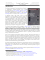
Gemini Control Program Version 1.1 a Companion Application to The Gemini Astronomical Positioning System® Levels 1 & 2 Users Manual Michael Rudolph Daniel Görlich Author: Michael Rudolph e-Mail: [email protected] Release Date: March 3rd, 2002 Gemini Control Program Users Manual Programmer: Daniel Görlich e-Mail: [email protected] Website: http://www.docgoerlich.de Table of Contents Introduction _________________________________________________ 2 1. 1.1. 1.2. 2. 2.1. 2.2. 2.3. 2.4. 2.5. 2.6. 2.7. 3. 3.1. 3.2. Installation & Startup 3 The Restart Screen _______________________________________ 3 The Initial Alignment Screen _______________________________ 4 ______________________________________ The Main GCP Window ____________________________________ 6 The Profile Screen _______________________________________ 8 The Hardware Screen _____________________________________ 9 The Site Screen _________________________________________________ 11 The Session Screen _____________________________________________ 12 The Modeling Screen ___________________________________________ 13 The Catalogs Screen ____________________________________________ 15 The Gemini Log Screen _________________________________________ 17 The Manual Control & Schedule Screen __________________ 19 Manual Control _________________________________________________ 19 The Observation Schedule _______________________________________ 20 1 Author: Michael Rudolph e-Mail: [email protected] Release Date: March 3rd, 2002 Gemini Control Program Users Manual Programmer: Daniel Görlich e-Mail: [email protected] Website: http://www.docgoerlich.de Introduction The Gemini Astronomical Positioning System (Gemini) is a sophisticated computer-controlled servo system developed jointly by Scott Losmandy1 and René Görlich.2 It is currently available for the Losmandy G-8, G-11, and HGM-200 German Equatorial Mounts, 3 for the Mountain Instruments MI-250,4 and also for the Celestron CI-700.5 A significant virtue of the Gemini is that it is fully functional in the field without the need of separate PC control, yet is also capable of being driven remotely by a P.C. using planetarium or other control software. While such third-party software is often able to perform the basic “Goto” functions of slewing to and guiding on celestial objects, none is capable of remotely performing all of the functions of which the Gemini is capable. Consequently, despite such software's value in its area of specialty, the operator must, nevertheless, remain with his telescope. The Gemini Control Program (GCP) developed by Daniel Görlich6 is a giant step toward complete remote control and automation. With it, the operator can set most Gemini parameters remotely, can access extended databases, and can program observing sequences through user-defined entries. Also, he or she is freed from having to scroll through multiple menus of the Hand Controller, and from the difficulty of having to accomplish everything through five buttons and an LED display. In short, the Gemini Control Program serves as both a user-friendly interface, and a customizable vehicle for operating a Gemini-connected telescope with control room comfort. There are two exceptions to total remote control of a telescope. The first and most obvious is that, as in all equipment, the optical, mechanical and electrical components of a telescope system can fail and, when they do, on-site access is absolutely necessary. A second exception is that a telescope's polar and initial star alignment must be performed at the telescope, and must be periodically confirmed. The Gemini Control Program does not perform these functions, but does provide the most dependable, easy-to-operate remote control of the Gemini Astronomical Positioning System that there is. The Gemini Control Program is designed to be used primarily with Level 2 Gemini firmware. While it may also be used with Level 1, its functions when so used are greatly reduced and consequently, Level 1 Gemini owners who wish to remotely control their systems are urged to upgrade to Level 2. Finally, this GCP Users Manual is intended to be used in conjunction with the Gemini System User Manual available at René Görlich's website. 1 2 3 4 5 6 Scott Losmandy. Website: http://www.losmandy.com – e-Mail: [email protected] René Görlich. Website: http://www.docgoerlich.com – e-Mail: [email protected] Losmandy Astronomical Product: Equatorial Mounts: http://www.losmandy.com/eq-mounts.html Mountain Instruments MI-250 Go -To: http://www.mountaininstruments.com/pages/mi250Go -To.html Celestron CI-700 German Equatorial Mount: http://www.celestron.com/access/ci700.htm Daniel Görlich. Website: http://www.docgoerlich.com – e-Mail: [email protected] 2 Author: Michael Rudolph e-Mail: [email protected] Release Date: March 3rd, 2002 Gemini Control Program Users Manual Programmer: Daniel Görlich e-Mail: [email protected] Website: http://www.docgoerlich.de 1. Installation & Startup The Gemini Control Program (GCP) can be operated from any PC running Windows, version 95 or newer. The only other requirements are the availability of a serial port capable of at least 9600 Baud, and 1 MB of hard disk space. The GCP can be downloaded as a zip file from René Görlich’s web site. 7 Unzip the file into any directory on your PC, being sure to keep all resulting files together. Since the four initially provided “.gcf” files are intended as templates to assist you in constructing your own observation profiles, it behooves you to protect them from accidental erasure by setting them to “read-only” in Windows Explorer. In preparation for launching the program, locate the “Gemini.exe ” file in Windows Explorer, and create a shortcut icon on the Windows desktop. The GCP may then be launched conveniently by double-clicking the icon. The Gemini Control Program communicates with the Gemini positioning device vía a special cable connected from the device to the serial port on your computer. This cable may either be purchased, or constructed according to the pin assignments described in either of the Gemini manuals (for Levels 1 or 2) downloadable from René Görlich's web site. 8 If the cable is connected, Gemini is turned on and GEMINI CONTROL is set to the active COM port or to AUTO-Detect, a computer link is made as soon as the GCP is launched. 1.1. The Restart Screen This screen appears whenever the Gemini is powered up following an observing session wherein an initial star alignment (“Initial Align”) was either performed during that session or remembered from a previous one. The RESTART SCREEN will not appear if the Gemini was previously shut down after a cold start or a warm start which was not followed by an “Initial Align.” In such cases, an INITIAL ALIGNMENT SCREEN appears in order to remind the user that he or she must do an “Initial Align” with the Hand Controller at the telescope before any Goto operation can be performed. 7 8 Gemini Control Program. Download from http://www.docgoerlich.de/Rene.html Gemini Users Manual. Level 1: http://www.docgoerlich.de/manL1V21/manual21.html Level 2: http://www.docgoerlich.de/manL2V11/manL2V11.html 3 Author: Michael Rudolph e-Mail: [email protected] Release Date: March 3rd, 2002 Gemini Control Program Users Manual Programmer: Daniel Görlich e-Mail: [email protected] Website: http://www.docgoerlich.de The RESTART SCREEN displays four buttons labeled COLD START , WARM START , WARM RESTART , and QUIT. COLD START clears the Gemini’s memory of all modeling data from previous star alignments. After a cold start, the Gemini is poised to receive an initial star alignment (“Initial Align”) and any number of additional alignments necessary to build a new pointing model. This is the kind of start needed when the telescope is initially set up, or after it has been relocated and polar-realigned. WARM START causes the Gemini to remember its previous modeling data, but requires a new “Initial Align” because it has lost its pointing orientation. This is the kind of start needed when the telescope remains polar-aligned at its unchanged location, but has been hand-slewed by loosening its RA and/or DEC clutches. After the “Initial Align,” no further alignments are needed to restore its pointing accuracy. WARM RESTART causes the Gemini to remember both its previous modeling data and its orientation. It is the kind of start needed when there has been no change in the telescope's location and polar-alignment, and the RA and/or DEC clutches have not been loosened for any reason. After a warm restart, no star alignments are needed to retain the telescope's previous pointing accuracy. QUIT causes the Gemini Control Program to shut down, leaving the Gemini to be operated by its Hand Controller. For a fuller discussion of modeling and the various ways to start the Gemini, see the Gemini System Users Manual, which may be downloaded from René Görlich's website. 1.2. The Initial Alignment Screen Requires Gemini level 2 or higher This screen appears whenever the Gemini is powered up and needs an INITIAL ALIGN before the GCP can be used for pointing to celestial objects. Initial Alignments are done with the Hand Controller at the telescope, employing an Initial Alignment Star List that is resident on the Gemini. Sometimes, however, an observer wishes to do an INITIAL ALIGN on a star that is not on the alignment list. For such occasions, the I NITIAL ALIGNMENT SCREEN provides a means by which you can add any star to the list. Simply type the star's name, its current RA-Dec coordinates (corrected to the equinox of the day - 4 Author: Michael Rudolph e-Mail: [email protected] Release Date: March 3rd, 2002 Gemini Control Program Users Manual Programmer: Daniel Görlich e-Mail: [email protected] Website: http://www.docgoerlich.de - not its Epoch 2000 coordinates), 9 and click ADD. Then go to the telescope, locate and center the star, and select INITIAL ALIGN on the Hand Controller. The star you downloaded will appear in Hand Controller's LED, ready for Initial Alignment. 10 An Initial Alignment is the minimum necessary for the Gemini to be able to point the telescope to celestial objects. Additional Alignments, while not absolutely required, increase Gemini's pointing accuracy. If the PROCEED button is clicked without first doing an Initial Alignment, the user cannot perform Goto functions, but can do setup operations, such as setting the GCP's parameters, saving profiles, and doing manual slews. The Initial Alignment can be done later. QUIT causes the Gemini Control Program to shut down, leaving the Gemini to be operated by its Hand Controller. 9 10 See chapter 2.7, “The Catalogs Screen” for a further explanation of Epoch vs. Current coordinates. See chapter 2.7, “The Catalogs Screen” for an alternative way to download an Initial Alignment Star. 5 Author: Michael Rudolph e-Mail: [email protected] Release Date: March 3rd, 2002 Gemini Control Program Users Manual Programmer: Daniel Görlich e-Mail: [email protected] Website: http://www.docgoerlich.de 2. The Main GCP Window The Gemini Control Program opens to a Window that contains a central panel of selectable screens. The first screen that appears after startup is the PROFILE S CREEN containing the “Losmandy Standard.gcf” profile template. To the left of the central screen are seven buttons that selectively determine which screen is displayed at any given time. In the upper right corner of the MAIN GCP WINDOW are six function buttons partially encircling an icon of the moon (also a button). The first of these buttons ( ) toggles the size of the MAIN GCP WINDOW for optimal viewing in either 800X600 or the default resolution of the computer. The second button ( ) launches a MANUAL CONTROL & SCHEDULE SCREEN to be described later. The third button ( ) toggles the background from opaque to transparent in order to be able to view the MAIN GCP Window simultaneously with the Windows desktop. The fourth button ( ) minimizes the MAIN GCP WINDOW to a small icon on the tray bar; leftclicking the minimized icon restores the window, and right-clicking the icon allows you to either quit the program or access the MANUAL CONTROL & SCHEDULE SCREEN. The fifth button ( ) closes the program. The sixth button ( ) displays credits, a copyright notice, and legal disclaimer. 11 Finally, the “moon” button ( ) toggles the display to night vision mode (red) for comfortable night viewing. At the bottom of the MAIN GCP WINDOW is a display panel containing time settings, control settings, telescope position, and Initial Alignment status. 11 This screen may be closed by clicking anywhere on it, or by typing any key. 6 Author: Michael Rudolph e-Mail: [email protected] Release Date: March 3rd, 2002 Gemini Control Program Users Manual Programmer: Daniel Görlich e-Mail: [email protected] Website: http://www.docgoerlich.de COMPUTER LOCAL TIME and COMPUTER UTC TIME are functions of the date/time and timezone settings in the computer's Control Panel. They are immediately displayed upon launching the GCP, whereas GEMINI LOCAL TIME, derived from the Gemini's internal clock and Gemini's Timezone setting, is only displayed when the Gemini and the computer are linked. POSITION is the point coordinate on the celestial sphere (expressed as right ascension and declination) to which the telescope is pointing. This value can only be displayed when the Gemini and the computer are linked, and an Initial Alignment has been performed. INITIAL ALIGNMENT indicates whether or not an Initial Alignment has been done. This status only displays in Gemini Level 2 or higher. BRIGHTNESS refers to both the LED display of the Gemini, and the PC monitor. The brightness display on the GCP defaults to 100% (maximum brightness), but may be edited by selecting another value from the drop-down menu. In night vision mode, the PC's brightness is automatically conformed to the Gemini's settings, but never goes lower than 40%, although the Gemini's LED can go as low as 6%. Finally, STARDATE is the local mean sidereal time (LST) derived from the PC's clock/date and geographic coordinates. It is the right ascension (RA) of all points on the current meridian of the celestial sphere, and is related to the hour angle (HA) of a telescope's RA setting circle by the equation HA=LST-RA. STARDATE is therefore useful for positioning the telescope, and for planning an observation sequence of celestial objects at or near the meridian. 7 Author: Michael Rudolph e-Mail: [email protected] Release Date: March 3rd, 2002 Gemini Control Program Users Manual Programmer: Daniel Görlich e-Mail: [email protected] Website: http://www.docgoerlich.de 2.1. The Profile Screen This screen is accessed vía the PROFILE button in the MAIN GCP WINDOW . A profile is a retrievable collection of settings and databases intended for use in a particula r observing session or project. For example, the user may set his location to Madrid, his slewing speed to 800, and his tracking speed to sidereal. He may then assign the name “Lyra Project” to this profile, and save it. When it is needed again for a future observing session, it may be retrieved by selecting “Lyra Project” from the CURRENT PROFILE pull-down menu, and clicking the button marked LOAD. There are four templates provided from which you may customize your own profiles; they are “Losmandy Standard.gcf” for the Losmandy and Celestron Level 2 Geminis, “Losmandy_L1V21.gcf” for the Losmandy and Celestron Level 1 Gemini, “Mountain Instruments Standard.gcf” for the Mountain Instruments Level 2 Gemini, and “MI_L1V21.gcf” for the Mountain Instruments Level 1 Gemini. The profile that appears the first time GCP is launched is “Losmandy Standard.gcf.” On subsequent startups the profile which first appears is the last one used. If that is not the profile needed, another may be selected vía the pull-down menu. The PROFILE SCREEN contains four buttons for managing profiles. The LOAD button activates the profile displayed in the CURRENT PROFILE BOX. The RELOAD button performs the same function, except that in the midst of typing a new profile name, clicking the RELOAD button restores the previously activated profile. The SAVE button stores all of the PROFILE, HARDWARE, SITE, S ESSION, and MODELING settings, under the profile name that appears in the CURRENT P ROFILE BOX. The DELETE button erases the profile displayed in the CURRENT PROFILE BOX, leaving a blank that must be replaced before proceeding. 8 Author: Michael Rudolph e-Mail: [email protected] Release Date: March 3rd, 2002 Gemini Control Program Users Manual Programmer: Daniel Görlich e-Mail: [email protected] Website: http://www.docgoerlich.de AUTO- SAVE initially defaults to OFF, but remains in the state in which it is when its profile is saved. When it is set to ON, all profile parameters are automatically saved when the program is shut down. In the center of the P ROFILE SCREEN is the COM port pull-down menu. If you know the COM port to which the Gemini is connected, you should sele ct it. If not, select AUTO- DETECT in order to direct the GCP to search COM1 through COM4 in an attempt to automatically locate the proper port connection. The Offline option is used when you want to let other programs such as TheSky®12 share the same port as the Gemini. For example, if you want to switch telescope control to TheSky®, you first go offline with the GCP, and then link to TheSky®. When you want to switch back, you reverse the procedure. You go offline with TheSky®, select the appropriate GCP COM port (or Auto-detect), and click RECEIVE CURRENT SETTINGS to synchronize the GCP with the Gemini. At the bottom of the PROFILE SCREEN are entry sites for three parameters. CACHE DELAY (default 1000 msecs.) specifies the number of milliseconds the system waits before informing the Gemini that a GCP setting was changed. REPLY TIMEOUT (default 0150 msecs.) specifies the number of milliseconds allowed for the system's reply, and UPDATE INTERVAL (1000 msecs.) specifies the number of milliseconds between synchronization of the GCP and the Gemini. By default, the program asks for current parameter settings every second, except for date and time, which are every ten seconds. The UPDATE INTERVAL must be set to at least 6 times the REPLY TIMEOUT. Under normal circumstances, these parameters should not have to be changed. The PROFILE S CREEN contains 2 buttons for uploading and downloading Gemini profile settings. The S END CURRENT SETTINGS button downloads the current GCP profile settings to the Gemini device. The RECEIVE CURRENT S ETTINGS button does the opposite – it uploads the Gemini settings to the GCP, but does not save them as a profile unless the SAVE button is pressed. Finally, the TOGGLE LOW PRECISION button does exactly what its name suggests – it switches the Gemini in and out of low precision (See the Gemini manual for circumstances which require that the Gemini be set in its low precision mode). To create and name a new profile, begin by loading an existing profile or profile template. To do this, select a suitable profile from the CURRENT PROFILE pull-down menu and click LOAD. Next, click to highlight the CURRENT PROFILE BOX, type in the new profile's name, and click on SAVE. This new profile contains all of the settings of the profile from which it was created. You may now navigate to the other screens, change any or all of the settings, return to the PROFILE S CREEN, and again click on SAVE to save your new profile with its new settings. 2.2. The Hardware Screen Requires Gemini level 2 or higher This screen is accessed vía the HARDWARE button in the MAIN GCP WINDOW ; it consists entirely of entry sites for settings that define the telescope mount's characteristics. The MOUNT TYPE is selected from the list of mounts contained in its pull-down menu. 12 Bisque Astronomy Software: TheSky ®: http://www.bisque.com/Products/TheSky/TheSky.asp 9 Author: Michael Rudolph e-Mail: [email protected] Release Date: March 3rd, 2002 Gemini Control Program Users Manual Programmer: Daniel Görlich e-Mail: [email protected] Website: http://www.docgoerlich.de ENCODER options are also selected from a pull-down menu, the choices being USE ENCODER, TEST ENCODER, and I GNORE ENCODER. Since the Gemini servo has its own motor axis encoders, this item only applies if additional encoders are installed for hand slewing. If accessory encoders are installed, they may be disabled by selecting I GNORE ENCODER. If none are installed, this feature performs no function. RA RESOLUTION and DEC RESOLUTION entries default to –4096 but can be changed. As with the ENCODER options, these entries perform no function if accessory encoders are not installed. Four MOVING SPEEDS may be entered as multiplicative coefficients of sidereal speed ( 15 arcsecssec ). MANUAL SLEW and GOTO SLEW are relatively fast movements, and their entries may be as high as 1440. CENTERING is done relatively slowly, and so its entry may not exceed 255 times the sidereal rate. GUIDING is the slowest movement, ±0.2 to 0.8 times the tracking rate. Five TRACKING SPEEDs may be selected from a pull-down menu. SIDEREAL is selected for tracking stars and other objects appearing stationary with respect to stars. LUNAR is selected for tracking the moon, SOLAR for tracking the sun, and NONE/TERRESTRIAL when tracking is not desired. KING RATE deserves special mention. It adapts the telescope's tracking rate to the apparent speed of a celestial object that is influenced by atmospheric refraction because it is located near the horizon. The King Rate is therefore a function of the observer's geographic coordinates and the pointing direction of the telescope (See the Gemini System Users Manual for greater detail). The SESSION SCREEN contains an identical TRACKING SPEED pull-down menu; both menus reflect changes made in the other. 10 Author: Michael Rudolph e-Mail: [email protected] Release Date: March 3rd, 2002 Gemini Control Program Users Manual Programmer: Daniel Görlich e-Mail: [email protected] Website: http://www.docgoerlich.de TVC VALUE can be set anywhere between 0 and 255. It is a means for eliminating hysteresis when changing directions in DEC, and is only active in Photographic Mode. The SESSION SCREEN also has a field for entering and viewing TVC VALUE; both screens reflect TVC value changes made in the other. Finally, S ET SAFETY LIMIT has a button to its right that is labeled NOW . Although the Gemini has default RA safety limits, you may have to change the limits when adding devices such as cameras to the OTA or knobs or other protrusions to the mount. To do this, slew the OTA in RA to the first limit you want to set, and click on NOW . Do this for the other limit as well. 2.3. The Site Screen This screen is accessed vía the SITE button in the MAIN GCP WINDOW . SITE means observing location, and is described both geographically and in real- time. Multiple sites can be defined and stored for later retrieval and incorporation into user profiles. Sites do not exist independent of the profiles of which they are a part. As a beginning, the profile templates provided with the GCP include lists of cities and regions with their respective time zones and geographic coordinates. You may use the closest site provided but, for most purposes, that will not be accurate enough, and you will want to define your own sites. To access a SITE that is already on the list, select it from the SITE pull-down menu. To create and save a site that is not yet part of the site list, highlight the SITE BOX, and replace its contents with a new descriptive name (e.g. “Home”). As soon as the GCP recognizes that a 11 Author: Michael Rudolph e-Mail: [email protected] Release Date: March 3rd, 2002 Gemini Control Program Users Manual Programmer: Daniel Görlich e-Mail: [email protected] Website: http://www.docgoerlich.de new name is being typed, an ADD button appears. When you have finished typing the name, click ADD. 13 At this point, the settings of this new site are still those of the previous one, so you must change them to your specifications. When you have made the changes, click REPLACE, then go to the PROFILE SCREEN and click SAVE. 14 If a site is created and saved in one profile, it does not automatically appear in the site list of another profile. To delete a site on the list, first select it from the pull-down menu, and then click REMOVE. The menu box will go blank and an ADD button will appear. You may now either type in a new site name and click ADD, or select another site from the pull-down list. In either case, the site you deleted has been removed from the list. The LONGITUDE and LATITUDE of the site are edited by first entering a plus (+) or a minus (-), and then entering degrees (2 digits) and minutes (2 digits). For longitude, (+) means West and (-) means East; for latitude, (+) means North, and (-) means South. TIMEZONE is entered as UTC ±n, where n is the number of hours that local standard time is ahead of or behind UTC. For example, the timezone in Chicago is UTC-5. Consequently, when the local standard time in Chicago is 13:00 EST, UTC is 18:00. GEMINI TIME and GEMINI DATE are automatically uploaded from the Gemini when it is linked to the GCP (Date and time are not stored as part of profiles). The S YNCHRONIZE DATE and SYNCHRONIZE TIME buttons are provided to conform the Gemini's date and time to that of the PC that is running the GCP. The procedural sequence for maximizing date and time accuracy is 1) Set the PC's timezone, date and time using a clock, NTP, SNTP or a GPS receiver 2) Launch the Gemini Control Program 3) Load a suitable profile (if desired) 4) Click on S YNCHRONIZE DATE 5) Click on S YNCHRONIZE TIME If, after launching the GCP or loading a profile you change Gemini's TIMEZONE, be sure to synchronize the date and time a second time. Also, be sure that the TIMEZONE of the GCP and your PC are always the same. A time alarm is provided by the Gemini to time photographic exposures. ALARM TIME is set in hours, minutes and seconds, and the alarm is set when SET ALARM is ON. An additional feature of the alarm is that when the designated time has been reached, a signal is sent to pin 1 of the AG port where a control can be installed to close a camera shutter automatically. 2.4. The Session Screen Requires Gemini level 2 or higher This screen is accessed vía the S ESSION button in the MAIN GCP WINDOW . 13 14 Caution! The new site has been added to the site list, but is impermanent because it has not yet been saved as part of a profile . Caution! If you do not click REPLACE , the changes you have made will remain operative on the SITE SCREEN, but will not be stored in the profile for future retrieval. 12 Author: Michael Rudolph e-Mail: [email protected] Release Date: March 3rd, 2002 Gemini Control Program Users Manual Programmer: Daniel Görlich e-Mail: [email protected] Website: http://www.docgoerlich.de The S ESSION NAME BOX comes equipped with three sample names that can be changed or deleted. To add a session name, type it in the SESSION NAME BOX, and when an ADD button pops up, click it. The REPLACE button performs a similar function to that of the REPLACE button in the SITE SCREEN. A session name can be deleted by clicking REMOVE. When the SESSION NAME BOX becomes blank, either type a replacement name and click ADD, or select another name from the SESSION pull- down menu. The HAND CONTROLLER BOX displays the mount's current Hand Controller mode, and its pulldown menu enables the user to change modes from the GCP. This selection only affects the operation of the Hand Controller, and has no affect on the MANUAL CONTROL SCREEN settings of the GCP. The TRACKING SPEED and TVC VALUE fields are duplicates of, and serve the same function as, their counterparts in the HARDWARE SCREEN. When they are changed in one screen, the changes are reflected in the other. TVC VALUE is the only setting on the SESSION S CREEN that is not saved when REPLACE is clicked. It is, however, saved with the profile. 2.5. The Modeling Screen Requires Gemini level 2 or higher This screen is accessed vía the M ODELING button in the MAIN GCP WINDOW . 13 Author: Michael Rudolph e-Mail: [email protected] Release Date: March 3rd, 2002 Gemini Control Program Users Manual Programmer: Daniel Görlich e-Mail: [email protected] Website: http://www.docgoerlich.de The initial star alignment is done at the telescope, after the mount has been polar-aligned (also at the telescope). After that, additional alignments can be done from the GCP's CATALOGS SCREEN. The first time a star alignment (“Initial Align”) is done, a Gemini modeling algorithm initiates, and all internal modeling parameters are reset. After that, each subsequent star alignment (“Additional Align”) contributes to the growing model, causing ever- increasing accuracy in Gemini's ability to point to given celestial objects or coordinates. On each alignment, Gemini's modeling parameters are recomputed and collectively indicate the degree of telescope misalignment. The closer the parameters are to zero, the closer the telescope is to perfect alignment. It takes several star alignments to acquire meaningful modeling data. The first two “Additional Aligns” initiate an estimate of “Polar Misalignment” and, after subsequent alignments, “Non-Perpendicularities” are also calculated. The more alignments done, the better are the estimates. The “Modeling” parameters do not upload from the Gemini to the GCP automatically. To visualize the most recent parameters, click RECEIVE CURRENT SETTINGS in the CURRENT PROFILE S CREEN. This Manual cannot go further in explaining the significance of each modeling parameter; the user is therefore referred to the Gemini System User Manual for more information on modeling, and on performing initial and additional star alignments. 14 Author: Michael Rudolph e-Mail: [email protected] Release Date: March 3rd, 2002 Gemini Control Program Users Manual Programmer: Daniel Görlich e-Mail: [email protected] Website: http://www.docgoerlich.de 2.6. The Catalogs Screen Requires Gemini level 2 or higher This screen is accessed via the CATALOGS button in the MAIN GCP WINDOW . Its purpose is to create, save and manage user-defined catalogs of celestial objects and their equatorial (RADec) coordinates. The objects saved in a catalog can be retrieved, edited, downloaded to the Gemini, and used as targets for slewing. A User-Catalog is usually constructed by an astronomer to contain only those celestial objects needed for a particular night's observation, and in the order in which they will be observed. The internal databases of the Gemini are Epoch 2000 catalogs, but their data cannot be uploaded for use with the GCP. Consequently, René Görlich has made all of these catalogs available on his web site, from where they may be downloaded as text files to any convenient directory on your computer. Selected objects from these catalogs (or other catalogs) may then be cut and pasted into the OBJECT LIST BOX in the GCP CATALOGS SCREEN, forming the basis of a User-defined Catalog. Each GCP User-Catalog is a named text file with the suffix “.guc ”. 15 A User-Catalog can be created or edited 1) by typing its list of celestial objects and their respective coordinates directly into the OBJECT LIST BOX on the CATALOGS SCREEN, 2) by first creating the list in a word processor and copying the list to the OBJECT LIST BOX, or 15 The suffix “guc” stands for “Gemini User Catalog.” 15 Author: Michael Rudolph e-Mail: [email protected] Release Date: March 3rd, 2002 Gemini Control Program Users Manual Programmer: Daniel Görlich e-Mail: [email protected] Website: http://www.docgoerlich.de 3) by creating the list in a word processor, saving it as a text file with the suffix “.guc ”, and placing it in the same computer directory as the Gemini Control Program. If the first two methods are used, the list is saved as a catalog by typing its name in the CATALOG NAME BOX, and clicking SAVE. If the third method is used, the file will automatically be recognized as a User-Catalog by the GCP at startup, or when a profile is loaded. Each line in a catalog represents a celestial object. The syntax of the line must be as follows: ObjectName,hh:mm:ss,±dd:mm:ss# , where • • • ObjectName is the name of the object16 hh:mm:ss is the object's Right Ascension in hours, minutes, and seconds ±dd:mm:ss is the object's Declination in degrees, arc minutes, and arc seconds. A saved catalog of celestial objects can be loaded into the OBJECT LIST BOX by selecting its name in the CATALOG DROPDOWN MENU, and clicking LOAD. It can also be deleted from the catalog list by selecting it and clicking DELETE. Once celestial objects are placed in the OBJECT LIST Box either by loading or typing, several operations on them can be performed. We have already seen that they can be individually edited and saved as a named catalog. They can also be downloaded to the Gemini's User Database by clicking DOWNLOAD. Once there, they can be used in every way that internal database objects can be used using Gemini's Hand Controller, and they can be added to by doing subsequent downloads. There is only one User Database on the Gemini, and all objects downloaded to it cumulate there until erased by clicking CLEAR. They can also be retrieved to the GCP's OBJECT LIST BOX by clicking UPLOAD. Celestial objects can be used directly from the OBJECT LIST BOX without downloading them. Most notably, an object can be slewed-to by highlighting it and then clicking GOTO 17 . When this is done, several new buttons appear, and the telescope immediately begins to slew toward the selected object. One of the buttons that appears is the EMERGENCY SLEW STOP. Its purpose is to stop the telescope's movement mid-slew whenever necessary. Two other buttons which appear after a slew are ADDITIONAL ALIGN and S YNCHRONIZE. The Initial Alignment that was performed when the Gemini was first powered up produces a pointing model accuracy that can be improved upon by doing several Additional Alignments. An Additional Alignment is done by slewing to the desired object, centering it in the telescope's field of view (using the GCP's MANUAL CONTROL or Gemini's Hand Controller), and then clicking ADDITIONAL ALIGN. The procedure for performing a star Synchronization is similar to that of an Additional Alignment but, whereas an Additional Alignment alters Gemini's pointing model, a Synchronization retains all of the modeling parameters, and merely shifts Gemini's internal frame of reference to a new coordinate on the celestial sphere. A common reason for doing a Synchronization is to compensate for drift caused by imprecise polar alignment. Another reason is to adjust for optical/mechanical offsetting movements such as the kind that 16 17 Since the User-Catalog's syntax supports only Latin fonts, all Greek characters should be represented by their Latin equivalents, e.g., a for α, b for β, etc. See the M ANUAL CONTROL & SCHEDULE SCREEN for other Goto operations. 16 Author: Michael Rudolph e-Mail: [email protected] Release Date: March 3rd, 2002 Gemini Control Program Users Manual Programmer: Daniel Görlich e-Mail: [email protected] Website: http://www.docgoerlich.de sometimes occurs when a diagonal is rotated. For more information on alignments and synchronizations, see the Gemini System User Manual on René Görlich's website. The RA-Dec coordinates of a Celestial object can be recorded in one of two ways – either Epoch (on the equinox of each 50th year – 12:00 UTC on January 1st – as in star catalogs), or Current (corrected to the equinox of the day). Over time, stars change their position on the celestial sphere relative to an observer on the earth. While there are several phenomena that cause this, the earth's precession is the most significant. Stars also appear to change their position as they approach the horizon; this is due to atmospheric refraction. 18 When constructing a user catalog for the Gemini, one must decide whether to use Epoch (50th year) or Current (corrected) coordinates. The choice should be made based upon how the catalog is to be used. For slewing or doing star alignments from the GCP, use Current coordinates. For downloading objects to Gemini's User Database in order to slew or do star alignments with the Hand Controller, use Epoch coordinates. The most convenient way to determine an object's Current coordinates (corrected to the date and time of observation), is with planetarium software such as TheSky® which provides both Epoch 2000 and Current coordinates for each catalogued object. 2.7. The Gemini Log Screen Requires Gemini level 2 or higher This screen is accessed vía the GEMINI LOG button in the MAIN GCP WINDOW . The log is a list of all actions the Gemini performs; it cumulates from observation to observation until it is manually cleared. The GEMINI LOG is uploaded from the Gemini to the LOG VIEWING BOX by clicking UPLOAD, and is erased from the Gemini by clicking CLEAR. The LOG VIEWING BOX can be cleared by highlighting its contents (Ctrl-A) and pressing “Del” on the computer keyboard. To save an uploaded log, highlight the LOG NAME BOX and replace its contents by typing in a new descriptive name (e.g. “Log Jan 2, 2002”). As soon as the GCP recognizes that a new log name is being typed, a SAVE button appears. When you have finished typing the name, click SAVE; the uploaded log is saved to a “.log” file, and three additional buttons appear – LOAD, RELOAD, and DELETE. To load a previously saved log file into the LOG VIEWING BOX, select its name from the LOG PULL-DOWN MENU, and click LOAD. The RELOAD button performs the same function as LOAD, except that in the midst of typing a new log name, clicking the RELOAD button restores the previous log. To delete a “.log” file which is not already in the LOG NAME BOX, select it from the LOG PULL-DOWN MENU, and click DELETE. If it is already in the LOG NAME BOX, just click DELETE. Logs are not saved as part of profiles. 18 Star catalogs cannot be republished every day or every week to account for progressive coordinate changes. They are, however, revised every 50 years, and the coordinates contained therein are known as Epoch 1900, Epoch 1950, Epoch 2000, etc. The most recent catalogs are Epoch 2000, and so all of the objects in Gemini's internal databases are recorded in Epoch 2000. 17 Author: Michael Rudolph e-Mail: [email protected] Release Date: March 3rd, 2002 Gemini Control Program Users Manual Programmer: Daniel Görlich e-Mail: [email protected] Website: http://www.docgoerlich.de Each line in the Gemini Log represents a single Gemini operation that has occurred. Its syntax is as follows: yymmddhhmmss$hh:mm:ss±dd:mm:ss&# , where • • • • • • yymmddhhmmss is the date and time (year, month, day, hour, minute, second) $ is a letter character representing one of the following Gemini operations: A… Additional Align C… Cold Start D… Realign (first Initial Align after a Warm Restart) G… Goto operation P… Primary (Initial) Align O… Power Off R… Warm Restart s… Synchronize S… Object Selection W…Warm Start hh:mm:ss is Right Ascension (hours, minutes, seconds) ±dd:mm:ss is Declination (± degrees, arc minutes, arc seconds) & is an object name up to 10 characters long (in S and G operations only) # is the line's termination symbol Typical Gemini Log entries are illustrated below: 020129121223S05:17:25+46:00:00Capella a Aur# 020129121223G05:16:40+45:59:53Capella a Aur# 020125223018O05:16:27+46:01:10# 18 Author: Michael Rudolph e-Mail: [email protected] Release Date: March 3rd, 2002 Gemini Control Program Users Manual Programmer: Daniel Görlich e-Mail: [email protected] Website: http://www.docgoerlich.de 3. The Manual Control & Schedule Screen This screen is accessed vía the MANUAL CONTROL & SCHEDULE SCREEN (MCSS) button in the upper right corner of the MAIN GCP WINDOW . This Screen is so named because it contains both manual and automated features. At the top left side of the screen is a MANUAL CONTROL area that employs four directional buttons (similar to Gemini's Hand Controller) for manually moving the telescope at selected speeds. Immediately below is a MANUAL TARGETING area for inputting and slewing to specified celestial coordinates. On the right side of the screen is an OBSERVATION SCHEDULE area where a list of celestial coordinates and their respective times can be entered for automatic slewing. To close the MCSS, click the button in the upper right corner; to defocus it, click anywhere on the MAIN GCP WINDOW . 3.1. Manual Control To move the telescope manually, one must first choose from among three movement options; these are GUIDING, CENTERING, or SLEWING, and are selected by clicking their respective buttons. Guiding and Centering derive their speeds from their respective settings in the HARDWARE SCREEN. Slewing, however, derives its speed from the dropdown menu in the MCSS itself. This feature allows the user to switch slew speeds quickly and conveniently. Slew speed set in the MCSS affects both Manual Control and Manual Targeting operations; it is a function of sidereal speed x ( 15 arcsecssec ) as follows: n°/s = (n*240)x, 1≤ n≤6, where n is an integer. There are five (5) buttons in the MCSS for Manual Control of the telescope. The E(ast) and W(est) buttons move the telescope in right ascension, while the N(orth) and S(outh) buttons move it in declination. The unlabeled button at the center (°) is the STOP button; clicking it stops all telescope movement. The directional buttons can operate in either Toggle Mode or Touch Mode, according to whether the TOUCH MODE CHECK BOX is checked. In Toggle Mode, a first click begins the telescope's motion, and a second click of the same button or the central button stops it. By clicking two buttons in sequence, the telescope can be moved in RA and Dec simultaneously. In Touc h Mode, motion of the telescope occurs while a directional button is depressed, and 19 Author: Michael Rudolph e-Mail: [email protected] Release Date: March 3rd, 2002 Gemini Control Program Users Manual Programmer: Daniel Görlich e-Mail: [email protected] Website: http://www.docgoerlich.de stops when it is released. 19 This mode is especially suitable for making fine movements; however, bi-directional movement in this mode is not possible. As previously stated, the MANUAL TARGETING area of the MCSS is for inputting and slewing to specified coordinates on the celestial sphere. To slew the telescope to a desired point, enter its current RA and Dec coordinate, and click GO 20 . As the telescope moves, its Current RA and Dec pointing position is displayed to the left of the TARGET RA and DEC input boxes. In emergencies, the telescope's movement can be stopped by clicking the unlabeled STOP button previously described. 3.2. The Observation Schedule The Observation Schedule of the MCSS derives its Goto Slew speed from the HARDWARE SCREEN. An Observation Schedule is a list of points on the celestial sphere and corresponding local times (computer time) when the telescope will automatically and sequentially slew to each point (this process is sometimes referred to as "scripting"). In emergencies, telescope movement can be stopped mid-slew by clicking the unlabeled STOP button previously described. To construct an Observation Schedule, enter a Slew Time, an Object Name, the current Right Ascension and Declination of a desired target point, and click ADD. Each time ADD is clicked, a new line is created and inserted into the list according to the time value entered. Any line in the list can be edited by highlighting it, making a change, and clicking REPLACE. Similarly, any line can be removed by highlighting it and clicking REMOVE; clicking C LEAR ALL removes all the lines at once. There are occasions where one may wish to construct an Observation Schedule but disable it from triggering when Slew Times are reached. This can be accomplished by clicking the DEACTIVATE SCHEDULE button. Similarly, to activate a deactivated list, click ACTIVATE SCHEDULE. Observation Schedules deactivate automatically after their last slew is triggered. Observation Schedules can also be used to perform Goto Slews at will, rather than at specified times21 . This can be accomplished by highlighting a line on the list and clicking INITIATE SLEW NOW .22 This feature is particularly useful when one must slew back and forth between specified objects such as when making photometric measurements. Observation Schedules and all current MCSS settings can be saved in profiles. This raises a need for caution because Observation Schedules saved while the y are active, revert to a deactivated state when they are reloaded, and must therefore be re-activated before they can be used. Also, keep in mind that Slew Times are independent of date, and an elapsed time will trigger again after 24 hours if the Observation Schedule is allowed to remain active. 19 20 21 22 The telescope does not stop instantaneously when mo ving at slew speed. Allowance must therefore be made for its additional travel while it is ramping down. See the CATALOGS SCREEN for a similar Goto operation. Again, see the CATALOGS SCREEN for a similar Goto operation. Slewing does not occur when the target coordinate is below the local horizon. No warning is given in such cases. 20 Author: Michael Rudolph e-Mail: [email protected] Release Date: March 3rd, 2002 Gemini Control Program Users Manual Notes 21 Programmer: Daniel Görlich e-Mail: [email protected] Website: http://www.docgoerlich.de